1
IBM System p HPC Clusters Fabric Guide using
InfiniBand Hardware
© Copyright IBM Corp. 2008 (7/22/08)
1 of 238
IBM System p HPC Clusters Fabric Guide using InfiniBand Hardware
Table of Contents
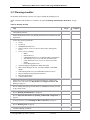
1.0 Document overview ......................................................................12
2.0 Clustering systems using InfiniBand hardware .........................14
2.1 Information resources ...........................................................................14
2.1.1 General cluster information resources ............................................................... 15
2.1.2 Cluster hardware information resources ............................................................ 15
2.1.3 Cluster management software information resources........................................ 16
2.1.4 Cluster software and firmware information resources....................................... 17
2.2 Fabric communications function overview .........................................18
2.2.1 IBM GX/GX+ HCA........................................................................................... 21
2.2.1.1
Logical Switch naming convention..................................................................................22
2.2.1.2
HCA Statistics counters...................................................................................................23
2.2.2 Vendor switches................................................................................................. 23
2.2.3 QLogic switches supported by IBM .................................................................. 23
2.2.4 Cables................................................................................................................. 23
2.2.5 Subnet Manager ................................................................................................. 24
2.2.6 Power Hypervisor .............................................................................................. 24
2.2.7 IBM device drivers ............................................................................................ 24
2.2.8 Non-IBM device drivers .................................................................................... 24
2.2.9 IBM host stack ................................................................................................... 24
2.3 Management subsystem function overview ........................................25
2.3.1 Management subsystem integration recommendations ..................................... 25
2.3.2 Management subsystem high level functions .................................................... 25
2.3.3 Management subsystem overview ..................................................................... 26
2.3.3.1
Switch Chassis Viewer Overview ....................................................................................29
2.3.3.2
Switch CLI Overview.......................................................................................................29
2.3.3.3
Fabric Manager Overview ..............................................................................................30
2.3.3.4
Fast Fabric Toolset Overview .........................................................................................31
2.3.3.5
CSM Overview.................................................................................................................31
2.3.3.6
HMC Overview................................................................................................................32
2.3.3.7
FSP Overview..................................................................................................................32
© Copyright IBM Corp. 2008 (7/22/08)
2 of 238
IBM System p HPC Clusters Fabric Guide using InfiniBand Hardware
2.3.3.8
Table of Contents
NTP Overview .................................................................................................................32
2.3.3.9
Fabric Viewer Overview .................................................................................................33
2.3.3.10
eMail Notifications Overview........................................................................................33
2.3.3.11
Server Operating System Overview...............................................................................33
2.3.3.12
Management Subsystem Networks ................................................................................34
2.3.4 Vendor log flow to CSM event management .................................................... 35
2.4 Supported components in an HPC cluster ..........................................36
3.0 Cluster Planning ...........................................................................37
3.1 Planning Overview ................................................................................37
3.2 Required Level of support, firmware and devices .............................39
3.3 Server Planning......................................................................................40
3.4 Planning InfiniBand network cabling and configuration..................40
3.4.1 Planning QLogic InfiniBand switch configuration............................................ 41
3.4.1.1
Planning MTU.................................................................................................................42
3.4.1.2
Planning GID Prefixes ....................................................................................................43
3.4.2 Planning an IBM GX HCA configuration ......................................................... 43
3.4.2.1
IP subnet addressing restriction......................................................................................44
3.5 Management Subsystem Planning .......................................................45
3.5.1 Planning CSM as your Systems Management Application ............................... 46
3.5.2 Planning for QLogic Fabric Management Applications.................................... 47
3.5.2.1
Planning Fabric Manager and Fabric Viewer................................................................47
3.5.2.2
Planning Fast Fabric Toolset..........................................................................................54
3.5.3 Planning for Fabric Management Server ........................................................... 55
3.5.4 Planning Event Monitoring with QLogic and CSM .......................................... 56
3.5.5 Planning Remote Command Execution with QLogic from the CSM/MS......... 57
3.6 Frame Planning......................................................................................58
3.7 Planning Installation Flow....................................................................59
3.7.1 Key installation points ....................................................................................... 59
3.7.2 Installation Responsibilities By Organization ................................................... 59
© Copyright IBM Corp. 2008 (7/22/08)
3 of 238
IBM System p HPC Clusters Fabric Guide using InfiniBand Hardware
Table of Contents
3.7.3 Install responsibilities by units and devices....................................................... 60
3.7.4 Order of installation ........................................................................................... 61
3.7.5 Installation Coordination Worksheet ................................................................. 65
3.8 Important information for planning an HPC MPI configuration....66
3.9 Planning 12x HCA connections............................................................67
3.10 Planning Aids .......................................................................................68
3.11 Planning checklist ................................................................................69
3.12 Planning worksheets............................................................................70
3.12.1 Using planning worksheets .............................................................................. 70
3.12.2 Cluster summary worksheet............................................................................. 71
3.12.3 Frame and rack planning worksheet ................................................................ 72
3.12.4 Server planning worksheet............................................................................... 73
3.12.5 QLogic Switch planning worksheets ............................................................... 74
3.12.6 CSM Planning Worksheets .............................................................................. 76
3.12.7 QLogic Fabric Management worksheets ......................................................... 79
3.12.8 Worksheet examples ........................................................................................ 82
3.12.8.1
Frame planning worksheet example: ............................................................................83
3.12.8.2
Server planning worksheet example:.............................................................................84
3.12.8.3
Switch Planning Worksheet example: ...........................................................................85
3.12.8.4
CSM Planning worksheet example ................................................................................88
3.12.8.5
CSM Event Monitoring worksheet example ..................................................................89
3.12.8.6
General QLogic Fabric Management worksheet example ............................................89
3.12.8.7
Fabric Management Server worksheet example............................................................90
4.0 Installing an HPC Cluster that has an InfiniBand network .....92
4.1 IBM Service representative installation responsibilities ...................92
4.2 Cluster Expansion or partial installation ............................................93
4.3 Site setup for power, cooling, and floor...............................................93
4.4 Management subsystem installation and configuration ....................95
© Copyright IBM Corp. 2008 (7/22/08)
4 of 238
IBM System p HPC Clusters Fabric Guide using InfiniBand Hardware
Table of Contents
4.4.1 Management subsystem installation and configuration information for
expansion: ................................................................................................................... 98
4.4.2 Install and configure Service VLAN devices .................................................... 99
4.4.3 HMC Installation ............................................................................................. 100
4.4.4 CSM Management Server Installation............................................................. 101
4.4.5 Operating System Install Servers Installation.................................................. 102
4.4.6 Fabric Management Server Installation ........................................................... 103
4.4.7 Setup Remote Logging .................................................................................... 108
4.4.7.1
Using syslog on RedHat Linux-based CSM/MS ............................................................116
4.4.8 Remote Command Execution setup................................................................. 117
4.4.9 Server Install and Configuration with Management Consoles ........................ 120
4.5 Installing and configuring the cluster server hardware ................. 121
4.5.1 Server installation and configuration information for expansion .................... 121
4.5.2 Server hardware installation and configuration Procedure:............................. 122
4.6 Operating System installation and configuring the cluster servers125
4.6.1 Server installation and configuration information for expansion .................... 125
4.6.2 Operating System installation and configuring the cluster servers procedure: 126
4.7 InfiniBand switch installation and configuration for vendor switches
.................................................................................................................... 129
4.7.1 InfiniBand switch installation and configuration information for expansion.. 129
4.7.2 InfiniBand Switch installation and configuration procedure ........................... 129
4.8 Attach cables to the InfiniBand network.......................................... 134
4.8.1 Cabling the InfiniBand network information for expansion............................ 134
4.8.2 InfiniBand network cabling procedure: ........................................................... 134
4.9 Verify the InfiniBand network topology and operation ................. 136
4.10 Installing or replacing an InfiniBand GX host channel adapter . 139
4.10.1 Deferring replacement of a failing host channel adapter ............................... 140
4.11 Verifying the installed InfiniBand network (fabric) in AIX or
Linux .......................................................................................................... 142
4.11.1 Verifying the GX HCA connectivity in AIX................................................. 142
© Copyright IBM Corp. 2008 (7/22/08)
5 of 238
IBM System p HPC Clusters Fabric Guide using InfiniBand Hardware
Table of Contents
4.11.2 Verifying the GX HCA to InfiniBand fabric connectivity in Linux.............. 142
4.12 Fabric verification ............................................................................ 142
4.12.1 Fabric verification responsibilities:................................................................ 142
4.12.2 Reference documentation for Fabric verification procedures:....................... 142
4.12.3 Fabric verification tasks:................................................................................ 143
4.12.4 Fabric Verification Procedure........................................................................ 143
4.13 Runtime errors.................................................................................. 144
5.0 Cluster Fabric Management ......................................................145
5.1 Cluster Fabric Management Flow .................................................... 146
5.2 Cluster Fabric Management Components and their Use ............... 147
5.2.1 CSM ................................................................................................................. 147
5.2.2 QLogic Subnet Manager .................................................................................. 147
5.2.3 QLogic Fast Fabric Toolset ............................................................................. 147
5.2.4 QLogic Performance Manager......................................................................... 148
5.3 Cluster Fabric Management Tasks................................................... 149
5.4 Monitoring Fabric for Problems ....................................................... 149
5.4.1 Monitoring fabric logs from CSM/MS ............................................................ 150
5.5 Health Checks ..................................................................................... 151
5.5.1 Setting up periodic fabric health checks .......................................................... 151
5.5.2 Output files for Health Check .......................................................................... 154
5.5.3 Interpreting .diff files ....................................................................................... 157
5.5.4 Querying Status................................................................................................ 158
5.6 Remotely accessing QLogic management tools and commands from
CSM/MS .................................................................................................... 159
5.6.1 Remotely accessing QLogic switches from the CSM/MS............................... 159
5.7 Updating Code .................................................................................... 161
5.7.1 Updating Fabric Manager Code....................................................................... 161
5.7.2 Updating Switch Chassis Code........................................................................ 162
© Copyright IBM Corp. 2008 (7/22/08)
6 of 238
IBM System p HPC Clusters Fabric Guide using InfiniBand Hardware
Table of Contents
5.8 Finding and Interpreting Configuration Changes .......................... 162
5.9 Hints on using iba_report .................................................................. 163
6.0 Cluster service.............................................................................165
6.1 Cluster service overview .................................................................... 165
6.2 Service responsibilities ....................................................................... 165
6.3 Fault reporting mechanisms .............................................................. 165
6.4 Fault diagnosis approach ................................................................... 166
6.4.1 Types of events ................................................................................................ 166
6.4.2 Approach to link problem isolation ................................................................. 167
6.4.3 Reboot/repower scenarios................................................................................ 168
6.4.4 The importance of NTP ................................................................................... 168
6.5 Table of symptoms.............................................................................. 169
6.6 Service procedures.............................................................................. 172
6.7 Capturing data for fabric diagnosis.................................................. 174
6.7.1 Using script command to capture switch CLI output ...................................... 176
6.8 Capture data for Fabric Manager and Fast Fabric problems ....... 176
6.9 Mapping fabric devices ...................................................................... 177
6.9.1 General mapping of IBM HCA GUIDs to physical HCAs.............................. 178
6.9.2 Finding devices based on a known logical switch ........................................... 179
6.9.3 Finding devices based on a known logical HCA ............................................. 181
6.9.4 Finding devices based on a known physical switch port ................................. 183
6.9.5 Finding devices based on a known ib interface (ibX/ehcaX) .......................... 185
6.10 IBM GX HCA Physical port mapping based on device number . 187
6.11 Interpreting switch vendor log formats.......................................... 188
6.11.1 Log severities ................................................................................................. 188
6.11.2 Switch chassis management log format......................................................... 188
© Copyright IBM Corp. 2008 (7/22/08)
7 of 238
IBM System p HPC Clusters Fabric Guide using InfiniBand Hardware
Table of Contents
6.11.3 Subnet Manager log format ........................................................................... 189
6.12 Diagnosing link errors...................................................................... 191
6.13 Diagnosing and repairing switch component problems................ 194
6.14 Diagnosing and repairing IBM system problems.......................... 194
6.15 Diagnosing configuration changes .................................................. 194
6.16 Checking for hardware problems affecting the fabric ................. 194
6.17 Checking for fabric configuration and functional problems ....... 195
6.18 Checking InfiniBand configuration in AIX ................................... 195
6.19 Checking System Configuration in AIX......................................... 197
6.20 Checking multicast groups .............................................................. 198
6.21 Diagnosing swapped HCA ports ..................................................... 199
6.22 Diagnosing swapped switch ports ................................................... 199
6.23 Diagnosing performance problems ................................................. 200
6.24 Diagnosing and recovering ping problems..................................... 201
6.25 Diagnosing application crashes ....................................................... 201
6.26 Diagnosing management subsystem problems .............................. 202
6.26.1 Problem with event management or remote syslogging ................................ 202
6.26.1.1
Event not in CSM/MS:/var/log/csm/errorlog ..............................................................203
6.26.1.2
Event not in CSM/MS: /var/log/csm/syslog.fabric.notices ..........................................204
6.26.1.3
Event not in CSM/MS: /var/log/csm/syslog.fabric.info ...............................................206
6.26.1.4
Event not in log on fabric management server............................................................208
6.26.1.5
Event not in switch log ................................................................................................209
6.26.2 Re-configuring CSM event management....................................................... 209
6.27 Recovering from an HCA preventing a logical partition from
activating ................................................................................................... 211
6.28 Recovering ibX interfaces ................................................................ 212
© Copyright IBM Corp. 2008 (7/22/08)
8 of 238
IBM System p HPC Clusters Fabric Guide using InfiniBand Hardware
Table of Contents
6.28.1 Recovering a single ibX interface in AIX...................................................... 212
6.28.2 Recovering all of the ibX interfaces in an LPAR in AIX .............................. 213
6.28.3 Recovering an ibX interface tcp_sendspace and tcp_recvspace.................... 214
6.28.4 Recovering ml0 in AIX.................................................................................. 214
6.28.5 Recovering icm in AIX.................................................................................. 214
6.29 Recovering to 4K MTU .................................................................... 214
6.30 Re-establishing Health Check baseline........................................... 217
6.31 Verifying link FRU replacements ................................................... 217
6.32 Verifying repairs and configuration changes ................................ 218
6.33 Rebooting the cluster........................................................................ 219
6.34 Rebooting/Powering off an IBM System ........................................ 219
6.35 Counting Devices .............................................................................. 220
6.35.1 Counting Switches ......................................................................................... 221
6.35.2 Counting logical switches .............................................................................. 221
6.35.3 Counting HCAs.............................................................................................. 221
6.35.4 Counting End ports ........................................................................................ 222
6.35.5 Counting Ports ............................................................................................... 222
6.35.6 Counting Subnet Managers............................................................................ 222
6.35.7 Counting Devices Example............................................................................ 222
6.36 Handling EPO situations ................................................................. 223
6.37 Monitoring and Checking for Fabric Problems ............................ 224
7.0 Planning and Installation Worksheets......................................225
8.0 Appendix: Notices.......................................................................236
8.1 Trademarks ......................................................................................... 237
© Copyright IBM Corp. 2008 (7/22/08)
9 of 238
IBM System p HPC Clusters Fabric Guide using InfiniBand Hardware
Table of Figures
Figure 1: An InfiniBand network with four switches and four servers connected.......................................................14
Figure 2: Cluster components involved in data flow ...................................................................................................19
Figure 3: High-Level Software Architecture ...............................................................................................................20
Figure 4: Simple configuration with InfiniBand..........................................................................................................20
Figure 5: Management Subsystem Functional Diagram..............................................................................................27
Figure 6: Vendor Log Flow to CSM Event Management............................................................................................35
Figure 7: Typical Fabric Manager Configuration on a single Fabric Management Server..........................................49
Figure 8: Typical Fabric Management Server configuration with 8 subnets...............................................................50
Figure 9: High-level cluster installation flow ..............................................................................................................62
Figure 10: Management Subsystem Installation Tasks................................................................................................97
Figure 11: Setup remote logging ...............................................................................................................................108
Figure 12: Remote Command Execution Setup.........................................................................................................117
Figure 13: Cluster Fabric Management Flow ............................................................................................................146
© Copyright IBM Corp. 2008 (7/22/08)
10 of 238
IBM System p HPC Clusters Fabric Guide using InfiniBand Hardware
Table of Tables
Table 1: Content Highlights.........................................................................................................................................12
Table 2: General Cluster Information Resources.........................................................................................................15
Table 3: IBM Cluster Hardware Information Resources .............................................................................................15
Table 4: Cluster Management Software Information Resources .................................................................................16
Table 5: Cluster Software and Firmware Information Resources................................................................................17
Table 6: Main components in fabric data flow ............................................................................................................18
Table 7: Management subsystem server, consoles and workstations ..........................................................................28
Table 8: MTU Settings ................................................................................................................................................42
Table 9: Sample Installation coordination worksheet..................................................................................................65
Table 10: Example Installation coordination worksheet..............................................................................................66
Table 11: Recommended Fast Fabric tools and commands.......................................................................................147
Table 12: Cluster Fabric Management Tasks ............................................................................................................149
Table 13: Symbol error thresholds (24 hour cycle/4 hour intervals) .........................................................................153
Table 14: Symbol error thresholds (24 hour cycle/1 hour intervals) .........................................................................153
Table 15: Updating Code: References and Impacts...................................................................................................161
Table 16: Fault Reporting Mechanisms.....................................................................................................................165
Table 17: CSM/MS Fabric Event Management Log: Table of symptoms ................................................................169
Table 18: Hardware or Chassis Viewer LEDs: Table of symptoms ..........................................................................170
Table 19: Fast Fabric Tools: Table of symptoms ......................................................................................................170
Table 20: SFP: Table of symptoms............................................................................................................................171
Table 21: Other: Table of symptoms .........................................................................................................................171
Table 22: Service Procedures ....................................................................................................................................172
Table 23: GUID Formats ...........................................................................................................................................177
Table 24: Isolating link ports based on known information ......................................................................................177
Table 25: IBM GX HCA physical port mapping: from iba device and logical switch..............................................187
Table 26: QLogic Log Severities...............................................................................................................................188
Table 27: Counting Switch Chips in a Fabric............................................................................................................221
Table 28: Counting Fabric Ports................................................................................................................................222
© Copyright IBM Corp. 2008 (7/22/08)
11 of 238
IBM System p HPC Clusters Fabric Guide using InfiniBand Hardware
1.0 Document overview
This section is an overview of this document’s structure and how to go about reading it.
This document provides planning and installation information to help guide you through the process of installing a
cluster fabric that incorporates InfiniBand® switches. Information about how to manage and service a cluster using
InfiniBand hardware is also included.
This document is intended to serve as a navigation aid through the publications required to install the hardware
units, firmware, operating system, software or applications publications produced by IBM® or other vendors. It will
recommend configuration settings and an order of installation as well as be a launch point for typical service and
management procedures. In some cases, this document will provide detailed procedures instead of referencing
procedures that are so generic that their use within the context of a cluster is not readily apparent.
This document is not intended to replace existing guides for the various hardware units, firmware, operating
system, software or applications publications produced by IBM or other vendors. Therefore, most detailed
procedures that already exist in other documents will not be duplicated here. Instead, those other documents will be
referenced by this document.
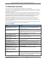
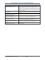
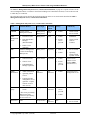
The document sections are roughly in the order in which you will need them. The following table gives you a highlevel outline of the document. Not all sub-sections are covered in the table.
Table 1: Content Highlights
Content
Description
Clustering systems using InfiniBand
hardware, on page 14.
Under this chapter, there are references to information resources
provided, an overview of the cluster components, and a section on
supported component levels.
Information resources, on page 14.
This details the various information resources for key components to
the Cluster fabric and how to get them. These resources are referenced
throughout the document. Therefore, it is very important to read this
and gather up required documents as soon as possible.
Fabric communications function
overview, on page 18
Discussion of fabric data flow
Management subsystem function
overview, on page 25.
Discussion of management subsystem
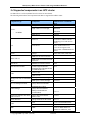
Supported components in an HPC
cluster, on page 36
Component supported and pertinent feature, software and firmware
minimum shipment levels.
Cluster Planning, on page 37
This chapter provides information for planning the cluster and its
fabric.
Planning Overview, on page 37.
This is a navigation guide for going about the planning process.
Required Level of support, firmware
and devices, on page 39.
This is minimum ship level information. It references a web-site to get
the latest information.
Server Planning (on page 40), Planning
InfiniBand network cabling and
configuration (on page 40), and
Management Subsystem Planning (on
page 45)
These are the main subsystems that need to be planned.
Planning Installation Flow, on page 59
This helps you understand how various tasks relate to each other as
well as who needs to do what. Finally, it illustrates how certain tasks
are prerequisites to others. With that information, you can coordinate
the installation team in a more efficient manner.
© Copyright IBM Corp. 2008 (7/22/08)
12 of 238
IBM System p HPC Clusters Fabric Guide using InfiniBand Hardware
Content
Description
Planning worksheets, on page 70
Planning worksheets are intended to cover the important cluster
aspects that affect the cluster fabric. You may have other worksheets
you wish to use, but they should cover the information in the provided
worksheets. These are duplicated at the end of the document to make
it easier to copy them.
Other planning
There are other planning sections that are referenced by the previous
sections.
Installing an HPC Cluster that has an
InfiniBand network, on page 92
Procedures for installing the cluster.
Cluster Fabric Management, on page
145
Contains best practices and tasks for managing the fabric.
Cluster service, on page 165
Contains high-level service tasks. This is intended to be the launch
point for servicing the cluster fabric components.
Planning and Installation Worksheets,
on page 225.
Another place for the planning worksheets. The intention is to make
these easier to copy than the versions in the planning overview.
Appendix: Notices, on page 236
Important notices.
© Copyright IBM Corp. 2008 (7/22/08)
13 of 238
IBM System p HPC Clusters Fabric Guide using InfiniBand Hardware
2.0 Clustering systems using InfiniBand
hardware
A variety of IBM® server hardware supports clustering through InfiniBand® host channel adapters (HCAs) and
switches. This guide provides planning and installation information to help guide you through the process of
installing a cluster fabric that incorporates InfiniBand switches. Information about how to manage and service a
cluster using InfiniBand hardware is also included.
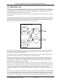
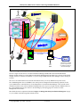
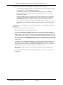
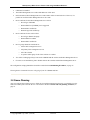
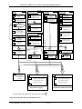
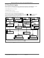
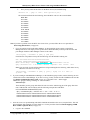
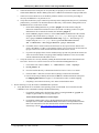
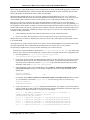
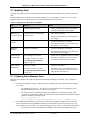
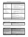
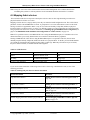
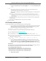
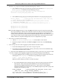
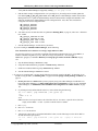
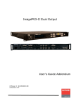
The following illustration shows servers that are connected in a cluster configuration with InfiniBand switch
networks (fabric). The servers in these networks can be connected through switches with IBM GX HCAs. In System
p™ Blade servers, the HCAs are PCI-e based.
Note:
1.
In this information, switch refers to the InfiniBand technology switch unless otherwise noted.
2.
Not all configurations support the following network configuration. Refer to your IBM sales information
for supported configurations.
Figure 1: An InfiniBand network with four switches and four servers connected
2.1 Information resources
The following tables indicate important documentation for the cluster, where to get it and when to use it relative to
Planning (Plan), Installation (Install), and Management and Service (Mgmt & Svc) phases of a cluster’s life.
© Copyright IBM Corp. 2008 (7/22/08)
14 of 238
IBM System p HPC Clusters Fabric Guide using InfiniBand Hardware
The tables are arranged into categories of components:
•
General Cluster Information Resources
•
Cluster Hardware Information Resources
•
Cluster Management Software Information Resources
•
Cluster Software and Firmware Resources
Pre-GA information is in this type of box. It will be withdrawn for GA.
2.1.1 General cluster information resources
General cluster information resources are found in the following Table 2: General Cluster Information
Resources.
Table 2: General Cluster Information Resources
Component
IBM Cluster
Guide
IBM Clusters
with the
InfiniBand
Switch web-site
QLogic™
InfiniBand
Architecture
HPC Central
wiki and HPC
Central forum
Document
This document
Plan
x
Install
x
Mgmt
& Svc
x
x
x
x
x
x
x
readme for IBM Clusters with the InfiniBand Switch
http://www14.software.ibm.com/webapp/set2/sas/f/network
manager/home.html
QLogic Best Practices Cluster Guide is initially available
from QLogic support. Check the IBM Clusters with the
InfiniBand Switch web-site for any updates to availability
on a QLogic web-site.
InfiniBand Architecture documents and standard
specifications are available from the InfiniBand Trade
Association http://www.infinibandta.org/home
The HPC Central wiki enables collaboration between
customers and IBM teams. The HCP Central wiki also
links to HPC Central forum where customers can post
questions and comments.
http://www941.ibm.com/collaboration/wiki/display/hpccentral/HPC+C
entral
Note: QLogic uses “Silverstorm” in their product documentation.
2.1.2 Cluster hardware information resources
Cluster Hardware Information Resources are found in the following Table 3: IBM Cluster Hardware Information
Resources.
Table 3: IBM Cluster Hardware Information Resources
Component
Site Planning
for all IBM
systems
POWER6™
systems:
Document
System i and System p Site Preparation and Physical
Planning Guide
Plan
x
Site and Hardware Planning Guide
Installation Guide for [MachineType and Model]
x
© Copyright IBM Corp. 2008 (7/22/08)
15 of 238
Install
x
Mgmt
& Svc
IBM System p HPC Clusters Fabric Guide using InfiniBand Hardware
Component
9125-F2A
8204-E8A
8203-E4A
Logical
partitioning for
all systems
BladeCenter® –
JS22
IBM GX HCA
Custom Install
BladeCenter
JS22 HCA
pass-thru
module
Fabric
Management
Server
Management
Node HCA
QLogic
switches
Document
Servicing the IBM system p [MachineType and Model]
PCI Adapter Placement
Worldwide Customized Installation Instructions (WCII)
IBM service representative install instructions for IBM
machines and features
http://w3.rchland.ibm.com/projects/WCII.
Plan
Install
x
x
x
Logical Partitioning Guide
Install Instructions for IBM LPAR on System i and System
p
Planning, Install & Service Guide
x
Mgmt
& Svc
x
x
x
x
x
x
x
x
x
x
x
x
x
x
HCA vendor documentation
x
x
x
[Switch Model] Users Guide
[Switch Model] Quick Setup Guide
QLogic InfiniBand Cluster Planning Guide
QLogic InfiniBand Cluster Troubleshooting Guide
QLogic 9000 CLI Reference Guide
x
x
x
x
x
x
x
Custom Install Instructions – one for each HCA feature
(http://w3.rchland.ibm.com/projects/WCII)
Users Guide
(Dale Weiler) – 1350TM documentation (Mellanox)
1350 docs… BOM & Mark Smolen
IBM System x™ 3550 & 3650 documentation
x
x
x
The base IBM system p (POWER6) documentation will be available in the IBM systems Resource Link™ found in:
http://www.ibm.com/servers/resourcelink, where you should start with the Library. Resource Link access requires
an IBM Registration ID (IBM ID).
The QLogic documentation is initially available from QLogic support. Check the IBM Clusters with the InfiniBand
Switch web-site for any updates to availability on a QLogic web-site.
Any exceptions to the location of information resources for cluster hardware as stated above have been noted in the
table.
Note: QLogic uses “Silverstorm” in their product documentation.
2.1.3 Cluster management software information resources
Cluster Management Software Information Resources are found in the following Table 4: Cluster Management
Software Information Resources..
Table 4: Cluster Management Software Information Resources
Component
QLogic Subnet
Manager
QLogic Fast
Fabric Toolset
Document
Fabric Manager and Fabric Viewer Users Guide
Plan
x
Install
x
Mgmt
& Svc
x
Fast Fabric Toolset Users Guide
x
x
x
© Copyright IBM Corp. 2008 (7/22/08)
16 of 238
IBM System p HPC Clusters Fabric Guide using InfiniBand Hardware
Component
QLogic
InfiniServ Stack
Document
InfiniServ Fabric Access Software Users Guide
Plan
x
Install
x
Mgmt
& Svc
x
Installation and Operations Guide for the HMC
x
x
Operations Guide for the HMC and Managed Systems
x
Cluster Systems Management: Planning and Installation
x
x
Guide
CSM
Cluster Systems Management: Administration Guide
x
Cluster Systems Management: Command and Technical
x
Reference
The HMC documentation is available along with the base System p (POWER6) documentation in the IBM systems
Resource link found in: http://www.ibm.com/servers/resourcelink, where you should start with the Library. You
can access the HMC documentation via the Resource Link requires an IBM Registration ID (IBM ID).
HMC
The IBM CSM documentation is available in two places.
• For the product library, go to:
http://publib.boulder.ibm.com/infocenter/clresctr/vxrx/topic/com.ibm.cluster.csm.doc/clusterbooks.html#aix_lin
ux17.
• For online documentation go to: http://publib.boulder.ibm.com/infocenter/clresctr/vxrx/index.jsp
The QLogic documentation is initially available from QLogic support. Check the IBM Clusters with the InfiniBand
Switch web-site for any updates to availability on a QLogic web-site.
2.1.4 Cluster software and firmware information resources
Cluster Software and Firmware Information Resources are found in the following Table 5: Cluster Software and
Firmware Information Resources.
Table 5: Cluster Software and Firmware Information Resources
Component
AIX®
Document
AIX Information Center
http://publib.boulder.ibm.com/infocenter/pseries/v5r3/index
.jsp?topic=/com.ibm.aix.doc/doc/base/aixinformation.htm
Plan
x
Install
x
Linux
Obtain from your Linux distribution source
GPFS: Concepts, Planning, and Installation Guide
GPFS: Administration and Programming Reference
GPFS: Problem Determination Guide
GPFS: Data Management API Guide
x
x
x
x
x
Tivoli Workload Scheduler LoadLeveler: Installation Guide
IBM HPC
Clusters
Software
x
x
x
Parallel Environment: MPI Programming Guide
Parallel Environment: MPI Subroutine Reference
© Copyright IBM Corp. 2008 (7/22/08)
17 of 238
x
x
x
x
Tivoli Workload Scheduler LoadLeveler: Diagnosis and
Messages Guide
Parallel Environment: Messages
Parallel Environment: Operation and Use, Vol 1 & 2
x
x
Tivoli Workload Scheduler LoadLeveler: Using and
Administering
Parallel Environment: Installation
Mgmt
& Svc
x
x
x
x
x
x
x
x
IBM System p HPC Clusters Fabric Guide using InfiniBand Hardware
Most of the links are listed along with the documents.
The IBM HPC Clusters Software Information can be found in two places:
• For the document library, go to:
http://publib.boulder.ibm.com/infocenter/clresctr/vxrx/topic/com.ibm.cluster.csm.doc/clusterbooks.html#aix_lin
ux17.
• For online documentation go to: http://publib.boulder.ibm.com/infocenter/clresctr/vxrx/index.jsp
2.2 Fabric communications function overview
The Fabric communications section describes the main components involved in application data flow. There are
several figures illustrating overall data flow and software layers in an IBM System p High Performance Computing
(HPC) cluster with an InfiniBand fabric.
It is highly recommended that you also review the following types of material to better understand InfiniBand
fabrics. More specific documentation references can be found in Information resources, on page 14.
1.
The InfiniBand standard specification from the InfiniBand Trade Association
2.
Documentation from the switch vendor
The following table lists the main components in fabric data flow and where to find an overview of them in this
document.
Table 6: Main components in fabric data flow
Component
IBM Host-Channel Adapters (HCAs)
Vendor Switches
Cables
Subnet Manager (within the Fabric Manager)
Phyp
Device Drivers (HCADs)
Reference
IBM GX/GX+ HCA, on page 21
Vendor switch, on page 23
Cables, on page 23
Subnet Manager, on page 24
Power Hypervisor, on page 24
IBM device drivers, on page 24
Non-IBM device drivers, on page 24
Host Stack
© Copyright IBM Corp. 2008 (7/22/08)
IBM host stack, on page 24
18 of 238
IBM System p HPC Clusters Fabric Guide using InfiniBand Hardware
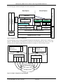
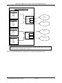
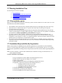
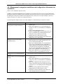
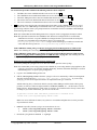
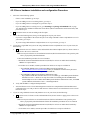
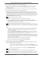
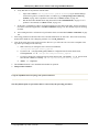
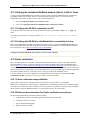
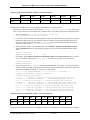
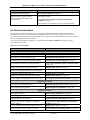
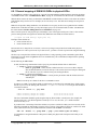
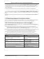
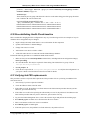
The following figure illustrates the main components involved in fabric data flow.
POWER6
Non-BladeCenter
AIX HCAD
Linux HCAD
Partition FW support
POWER6
BladeCenter
JS22
AIX HCAD
Linux HCAD
PHyp
FSP
Partition FW support
HMC
Firmware
Fabric Management
Fabric Management
Subnet Manager
Subnet Manager
InfiniBand Cables
InfiniBand Cables
InfiniBand switch
InfiniBand switch
Hardware
GX+ HCAs
4x DDR PCI-e HCA
POWER6 System
Legend:
IBM
POWER6 Blade
Vendor
Figure 2: Cluster components involved in data flow
© Copyright IBM Corp. 2008 (7/22/08)
19 of 238
IBM System p HPC Clusters Fabric Guide using InfiniBand Hardware
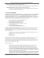
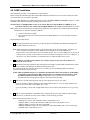
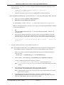
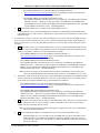
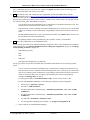
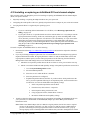
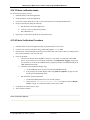
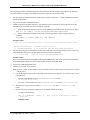
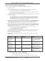
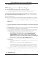
The following figure illustrates the high level software architecture:
User Space
Kernel Space
ESSL
CSM, RSCT
Load Leveler
GPFS
Parallel ESSL
IBM MPI
Sockets
TCP
VSD/NSD
LAPI
HAL - User Space Verbs
Linux Open IB or AIX InfiniBand Support
InfiniBand HCA – IBM or Vendor
HMC
InfiniBand Network - Vendor
UDP
IP
IF_LS
Fabric Management
DD
HYP
Operating Systems
Application
Figure 3: High-Level Software Architecture
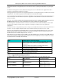
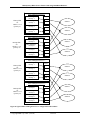
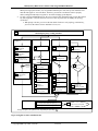
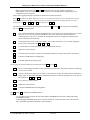
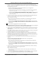
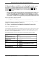
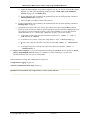
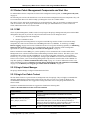
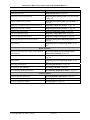
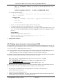
The following figure shows a simple InfiniBand configuration illustrating tasks, software layers, windows and
hardware. The illustrated HCA is intended to be an single HCA card with 4 physical ports. However, one could
interpret it also as a collection of physical HCAs and port; for example, two cards each with two ports.
Application Task
MPI/LAPI
InfiniBand HAL
SFIFO/
RFIO
SFIFO/
RFIO
Application Task
MPI/LAPI
InfiniBand HAL
InfiniBand VIRTUAL Window
InfiniBand VIRTUAL Window
HCA
HCA
Figure 4: Simple configuration with InfiniBand
© Copyright IBM Corp. 2008 (7/22/08)
20 of 238
Port 3
Port 2
Port 1
Port 0
Port 0
Port 1
Port 2
Port 3
InfiniBand Switch
IBM System p HPC Clusters Fabric Guide using InfiniBand Hardware
2.2.1 IBM GX/GX+ HCA
The IBM GX/GX+ host channel adapter (HCA) provides server connectivity to InfiniBand fabrics. Attaching to the
GX/GX+ bus provides much higher bandwidth to/from the adapter and therefore, better network performance than
using an adapter on a PCI bus. Because of server form factors including GX/GX+ bus design, each server that
support an IBM GX/GX+ HCA has its own HCA feature.
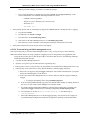
The GX/GX+ HCA has the ability to be shared between logical partitions (LPARs). Each physical port can be used
by each LPAR.
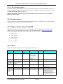
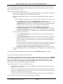
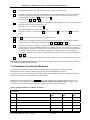
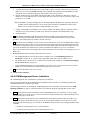
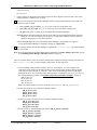
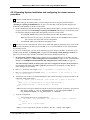
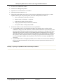
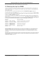
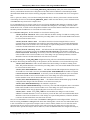
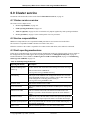
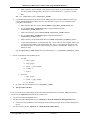
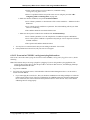
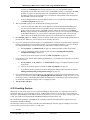
The adapter itself is logically structured as one logical switch connected to each physical port with a Logical Host
Channel Adapter (LHCA) for each logical partition. The following figure illustrates a single physical 2-port HCA.
This is realized with a single chip, which can support two ports. A 4-port HCA card has two chips with a total of 4
logical switches realized by having 2 logical switches in each of the 2 chips.
2 Port IBM GX/GX+ HCA
logical
HCA
logical
HCA
.
.
.
logical
HCA
logical
switch
Port 1
logical
switch
Port 2
logical
HCA
The logical structure affects how the HCA presents itself to the Subnet Manager. Each logical switch and logical
HCA presents itself as a separate InfiniBand node to the Subnet Manager on each port. Each logical HCA will
present itself to all logical switches in the HCA.
Each logical switch has a port Globally Unique Identifier (GUID) for the physical port and a port GUID for each
logical HCA. Each logical HCA has two port GUIDs; one for each logical switch.
The number of nodes that can be presented to the Subnet Manager is also a function of the maximum number of
LHCAs that can be assigned. This is a configurable number for POWER6 GX HCAs and it is a fixed number for
pSeries® Power 5 GX HCAs. The Power Hypervisor (PHyp) communicates with the Subnet Manager using the
Subnet Management Agent (SMA) function in Phyp.
The Power 6 GX HCA defaults to support a single LHCA. In this case, it presents each physical port to the Subnet
Manager as a 2-port logical switch where 1 port connects to the logical HCA (LHCA) and the second port connects
to the physical port.. The Power 6 GX HCA can also be configured to support up to 16 LHCAs. In this case, the
HCA presents each physical port to the Subnet Manager as a 17-port logical switch with up to 16 LHCAs.
Ultimately the number of ports for logical switch is dependent on the number of LPARs concurrently using the GX
HCA.
The Power 5 GX HCA supports up to 64 LHCAs. In this case, it presents each physical port to the Subnet Manager
as a 65-port logical switch where 1 port connects to the physical port and 64 ports connect to LHCAs. As opposed to
how it works on POWER6 systems, for Power 5 systems, it does not matter how many logical HCAs are actually
defined and used by Logical Partitions. The number of nodes presented includes all potential logical HCAs for the
© Copyright IBM Corp. 2008 (7/22/08)
21 of 238
IBM System p HPC Clusters Fabric Guide using InfiniBand Hardware
configuration; therefore, each physical port on a GX HCA in a Power 5 system presents itself as a 65-port logical
switch.
The Hardware Management Console (HMC) that manages the server in which the HCA is populated is used to
configure the virtualization capabilities of the HCA.
Each logical partition is only aware of its assigned logical HCA. For each partition profile, a GUID is selected with
a logical HCA. The GUID is programmed in the adapter itself and cannot be changed.
Since each GUID must be different in a network, the IBM HCA gets a subsequent GUID assigned by the Firmware.
You can choose the offset that should be used for the logical HCA. This information is also stored in the LPAR
profile on the HMC.
Therefore, when an HCA is replaced, each partition profile needs to be manually updated with the new HCA
GUID information. If this step is not performed, the HCA is not available to the operating system.
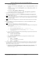
The following table describes how the HCA resources can be allocated to an LPAR. This ability to allocate HCA
resources allows multiple LPARs to share a single HCA. The degree of sharing is driven by application
requirements.
The Dedicated value is only used when you have a single active LPAR which needs to use all of the available HCA
resources. You may configure multiple LPARs to have Dedicated, but only one may be active at a time.
When you have more than one LPAR sharing an HCA, you can assign a particular allocation to it. You can never
allocate more than 100% of the HCA across all active LPARs. For example, four active LPARs could be set at
Medium and two active LPARs to High; (4*1/8) + (2*1/4) = 1.
If the requested resource allocation for an LPAR exceeds the available resource for an HCA, the LPAR will fail to
activate. So, in the above example with 6 active LPARs, if one more LPAR tried to activate on the HCA it would
fail, because the HCA is already 100% allocated,
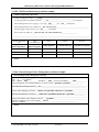
Value
Dedicated
Resulting Resource Allocation/Adapter
All of the adapter resources will be dedicated to the LPAR. This is the
default for single LPARs, which is the supported HPC Cluster
configuration.
If you have multiple active LPARs, you cannot simultaneously
dedicate the HCA to more than one active LPAR.
High
¼ of the maximum adapter resources
Medium
1/8 of the maximum adapter resources
Low
1/16 of maximum adapter resources
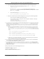
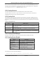
2.2.1.1 Logical Switch naming convention
The IBM GX HCAs have a logical switch naming convention based on the server type and the HCA type.
Server
HCA chip base
p5
Any
System p (POWER6)
Second Generation
Sysetem p (POWER6)
First Generation
© Copyright IBM Corp. 2008 (7/22/08)
Logical Switch Name
IBM Logical Switch 1 or
IBM Logical Switch 2
IBM G2 Logical Switch 1 or
IBM G2 Logical Switch 2
IBM G1 Logical Switch 1 or
IBM G1 Logical Switch 2
22 of 238
IBM System p HPC Clusters Fabric Guide using InfiniBand Hardware
2.2.1.2 HCA Statistics counters
The statistics counters in the IBM GX HCAs are only available from HCAs in System p (POWER6) servers. You
can query the counters using Performance Manager functions with the Fabric Viewer and Fast Fabric’s iba_report
(see Hints on using iba_report, on page 163).
While the HCA keeps track of most of the prescribed counters, it does not have counters for Transmit
Packets or Receive Packets.
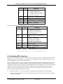
2.2.2 Vendor switches
Vendor switches are used as the backbone of the communications fabric in an IBM HPC Cluster using InfiniBand
technology. These are all based on the 24 port Mellanox chip.
2.2.3 QLogic switches supported by IBM
IBM supports QLogic switches in HPC Clusters. The following models are supported. For more details on the
models, see QLogic literature and the Users Guide for the switch model available at http://www.qlogic.com or
contact QLogic support. Note: QLogic uses SilverStorm in their product names.
•
9024 = 24 port
•
9040 = 48 port
•
9080 = 96 port
•
9120 = 144 port
•
9240 = 288 port
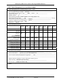
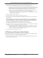
2.2.4 Cables
IBM recommends the following cables for supported HPC configurations.
System /
Use
POWER6
9125-F2A
Cable Type
4x DDR, copper
Connector
Type
QSFP – CX4
Length (m)
Source
6m (passive,
26awg), 10m
(active, 26awg),
14m (active,
30awg)
Vendor
Comments
POWER6
8204-E8A &
8203-E4A
JS22
12x – 4x DDR
width exchanger,
copper
4x DDR, copper
CX4 – CX4
3, 10
IBM
Link operates at 4x speeds
CX4 – CX4
Multiple lengths
Vendor
Intra-rack
Fabric
Management
Server
4x DDR, copper
4x DDR, copper
CX4 – CX4
CX4 – CX4
Multiple lengths
Multiple lengths
Vendor
Vendor
Used to connect between
PTM & switch
For use between switches
For connecting the Fabric
Management Server to
subnets to support hostbased Subnet Manager and
Fast Fabric Toolset.
© Copyright IBM Corp. 2008 (7/22/08)
23 of 238
IBM System p HPC Clusters Fabric Guide using InfiniBand Hardware
2.2.5 Subnet Manager
The Subnet Manager is defined by the InfiniBand standard specification. It is used to configure and manage the
communication fabric so that it can pass data. It does its management in-band over the same links as the data.
IBM recommends using a host-based Subnet Manager (HSM) which will run a Fabric Management Server. The
host-based Subnet Manager scales better than the embedded Subnet Manager, and IBM has verified and approved
the HSM.
See also Management subsystem, on page 25.
For more information on Subnet Managers, see the InfiniBand standard specification or vendor documentation.
2.2.6 Power Hypervisor
The Power Hypervisor (PHyp) provides an abstraction layer between the hardware/firmware and the operating
system instances. It provides functions to exploit Power 6 GX HCA implementations:
• UD Low Latency Receive Queues
• Large page memory sizes
• Shared Receive Queues (SRQ)
• Support for more than 16K Queue Pairs (QP). The exact number of QPs will be driven by cluster size
and available system memory
PHyp also contains the Subnet Management Agent (SMA) to communicate with the Subnet Manager and present the
HCA as logical switches with a given number of ports attached to the physical ports and to logical HCAs. For more
information, see IBM GX/GX+ HCA, on page 21.
Furthermore, PHyp contains the Performance Management Agent (PMA) used to communicate with the
Performance Manager which collects fabric statistics, such as link statistics, including errors and link usage
statistics.
For more information on SMA and PMA function see the InfiniBand architecture document available
2.2.7 IBM device drivers
IBM provides device drivers used in AIX.
2.2.8 Non-IBM device drivers
Non-IBM device drivers for Linux are available from the distributions.
Non-IBM device drivers are not supported on IBM System p HPC Clusters using AIX.
The vendor provides the device driver used on Fabric Management Servers. See Management subsystem, on page
25.
2.2.9 IBM host stack
The HPC software stack is supported for IBM System p HPC Clusters.
The vendor host stack is used on Fabric Management Servers. See Management subsystem, on page 25.
© Copyright IBM Corp. 2008 (7/22/08)
24 of 238
IBM System p HPC Clusters Fabric Guide using InfiniBand Hardware
2.3 Management subsystem function overview
The management subsystem is a collection of servers/consoles, applications, firmware and networks which work
together to provide the ability to:
-
Install and manage firmware on hardware devices
-
Configure devices and the fabric
-
Monitor for events in the cluster
-
Monitor status of devices in the cluster
-
Recover and route around failure scenarios in the fabric
-
Diagnose problems in the cluster
IBM and vendor system and fabric management products and utilities can be configured to work together to manage
the fabric.
It is highly recommended that you also review the following types of material to better understand InfiniBand
fabrics. More specific documentation references can be found in Information resources, on page 14.
1.
The InfiniBand standard specification from the InfiniBand Trade Association. Pay particular attention to
information on managers.
2.
Documentation from the switch vendor. Pay particular attention to Fabric Manager and Fast Fabric Toolset
documentation.
2.3.1 Management subsystem integration recommendations
Cluster Systems Management (CSM) will be the IBM systems management tool that provides the integration
function for InfiniBand fabric management. The integration leverages existing function within CSM. Major
advantages of CSM in a cluster are:
- The ability to issue remote commands to many nodes and devices simultaneously.
- The ability to consolidate logs and events from many sources in a cluster using event management.
- For more information on the functions and advantages of CSM, see CSM documentation.
The recommended switch and fabric management tools from QLogic are:
- Fabric Manager
- Fast Fabric Toolset
- Chassis Viewer
- Switch Command Line Interface
- Fabric Viewer
Managed switch models will be used in System p HPC Clusters.
2.3.2 Management subsystem high level functions
In order to address management subsystem integration, functions for management will be divided into the following
categories:
1. Monitor the state and health of the fabric
2. Maintain
3. Diagnose
4. Connectivity
In order to monitor the fabric:
1. We provide a method to get asynchronous events that indicate status and configuration changes into
the CSM event management subsystem. This is achieved by forwarding syslog entries from vendor
Subnet Managers and switches to the CSM Management Server (CSM/MS)
© Copyright IBM Corp. 2008 (7/22/08)
25 of 238
IBM System p HPC Clusters Fabric Guide using InfiniBand Hardware
2.
3.
4.
5.
The remote syslog entries arriving at the CSM/MS are directed to a file or named pipe based on
priority/severity of the log entry.
a. NOTICE and higher entries go to a file or named pipe that will be monitored by CSM event
management.
b. INFORMATION and higher entries go to another file for history and detailed debug
purposes. This is an optional approach, but highly recommended.
Event management will leverage the AIXSyslogSensor for CSM running on AIX, and the
ErrorLogSensor for CSM running on Linux.
Event management will place the NOTICE and higher log entries in the common area for error logs
from operating systems.
The QLogic Fast Fabric Toolset’s health check tools are highly recommended for regularly monitoring
the fabric for errors and configuration changes that could lead to performance problems.
a. A baseline health check is taken upon installation and configuration change.
b. The baseline is used to compare against current state and indicate any undesired differences.
In order to maintain the fabric, the dsh command in CSM will allow you to leverage existing vendor command-line
tools remotely from the CSM/MS. These tools are:
1. Switch chassis command line interface (CLI) on a managed switch. There are some new dsh options
and hardware device command profiles that allow dsh to work with the proprietary switch CLI. See
Remote Command Execution setup, on page 117, and Remotely accessing QLogic switches from
the CSM/MS, on page 159.
2. Subnet Manager running in a switch chassis or on a host
3. Fast Fabric tools running on a fabric management server/host. This host will be an IBM System x
server running Linux and the vendor’s host stack.
In order to diagnose the fabric and check the health of the fabric, we rely heavily on existing vendor tools:
1. The QLogic Fast Fabric Toolset running on the Fabric Management Server/Host is recommended to
provide the main diagnostic capability.
2. The QLogic Fast Fabric Toolset’s health check facility is especially important when there are no clear
events indicating a specific problem, but there is an observed degradation in performance. The
indicators of a problem in the fabric will be
a. Any errors that have gone previously undetected
b. Any configuration changes, including missing resource.
3. You can access vendor diagnostic tools using the CSM dsh command.
For connectivity, the CSM/MS must be on the same cluster VLAN as the switches and the management servers
running the Subnet Managers and Fast Fabric Tools.
2.3.3 Management subsystem overview
The management subsystem in the System p HPC Cluster solution using an InfiniBand fabric loosely integrates the
typical IBM System p HPC cluster components with the QLogic components.
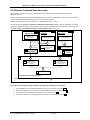
This section describes the management subsystem from several perspectives:
1.
Host view
2.
Networks
3.
Functional Components
4.
Users and interfaces
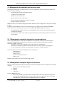
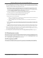
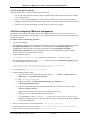
The Figure 5: Management Subsystem Functional Diagram, on page 27, illustrates the management or service
subsystem from a functional point of view.
© Copyright IBM Corp. 2008 (7/22/08)
26 of 238
IBM System p HPC Clusters Fabric Guide using InfiniBand Hardware
Service laptop
Servers
RS/232
Service
provider
Fabric Management Server
Fabric
Manager
I
P
OS
QLogic
Switch
Chassis
Viewer
I
B
FSP
CLI
Fast Fabric
Tools
Fabric
Viewer
NTP Server
Private
Admin desktop
CSM
HMC
GUI & RMC
IBM Call
Home
Admin
CE
IBM
Call Home is for IBM
systems only and does
not include switches or
the Subnet Manager
Figure 5: Management Subsystem Functional Diagram
The above figure assumes the use of a Host-based Subnet Manager (HSM) rather than an Embedded Subnet
Manager (ESM) running on a switch. IBM recommends the HSM instead of the ESM. This is because of the limited
compute resources on switches for ESM use. If you are using an ESM, then the Fabric Managers will be running on
switches.
The servers are monitored and serviced in the same fashion as they are for any IBM Power Systems cluster.
The CSM Management Server (CSM/MS) is the central point for management and monitoring operations for the
system administrator. CSM functions for event management of switch and Subnet Manager events, and for remote
command execution to the switches and Fabric Management Server may be leveraged from the CSM/MS. However,
the system administrator may also choose to do such things by directly logging on to switches or Fabric
Management Servers/Hosts.
More details about the components illustrated in Figure 5: Management Subsystem Functional Diagram, on page
27, are available in the following table and sub-sections.
© Copyright IBM Corp. 2008 (7/22/08)
27 of 238
IBM System p HPC Clusters Fabric Guide using InfiniBand Hardware
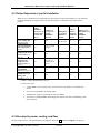
The Table 7: Management subsystem server, consoles and workstations, on page 28 is a quick reference for the
various management hosts or consoles in the cluster including who is intended to use them, as well as the networks
to which they are connected.
The subsequent sub-sections describe the applications that run on the servers and consoles described in Table 7:
Management subsystem server, consoles and workstations.
Table 7: Management subsystem server, consoles and workstations
Hosts
Software Hosted
Server Type
Operating
System
User(s)
Connectivity
CSM/MS
Cluster System
Management (CSM)
IBM System p
AIX or
Linux
1.
1.
Cluster VLAN
2.
Service VLAN
1.
Fast Fabric Tools
IBM System x
Linux
1.
Admin
1.
InfiniBand
2.
Host Based Fabric
Manager
(Recommended)
2.
Switch
service
provider
2.
Cluster VLAN
(same as
switches)
3.
Fabric Viewer
(optional)
1.
IBM CE
1.
Service VLAN
2.
Admin
2.
optionally,
Cluster VLAN
or public VLAN
1.
Admin
2.
Switch
service
provider
Cluster VLAN
(Chassis viewer
requires public
network access.)
Fabric
Management
Server
HMC
Switch
Admin
Workstation
Service
laptop
IBM System x
Hardware Management
Console for managing
IBM systems.
IBM system x
1.
Chassis firmware
Switch chassis
2.
Chassis viewer
3.
Embedded Fabric
Manager (optional)
1.
Admin workstation
2.
optionally, Fabric
Viewer
3.
Launch point into
management servers
(optional – requires
network access to
other servers)
1.
Serial interface to
switch
proprietary
proprietary
User
preference
User
preference
1.
Admin
Network access to
management servers
Laptop
User
preference
1.
Switch
service
provider
RS/232 to switch.
2.
Admin
* This is not provided by
IBM as part of the
cluster. It is provided by
the user or the site.
NTP Server
NTP
© Copyright IBM Corp. 2008 (7/22/08)
Admin
Site preference
Site
preference
N/A
28 of 238
1.
2.
Cluster VLAN
Service VLAN
IBM System p HPC Clusters Fabric Guide using InfiniBand Hardware
Note: The following sub-sections are broken down by application in the management subsystem.
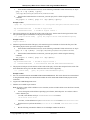
2.3.3.1 Switch Chassis Viewer Overview
Description
Documentation
When to Use
Host
How to access
The switch chassis viewer is a tool for configuring a switch, as well as a tool for querying its
state. It is also used to access the embedded fabric manager. Since it can only work with one
switch at a time, it does not scale well. Use the Fast Fabric Toolset and CSM to work with
multiple switches or multiple fabric managers simultaneously.
Switch Users Guide
After the configuration setup has been performed, the user will probably only use the chassis
viewer as part of diagnostics after the Fabric Viewer or Fast Fabric tools have been employed
and isolated a problem to a chassis.
Switch Chassis
The Chassis Viewer is accessible via any browser on a server connected to the Ethernet network
to which the switch is attached. The switch’s IP address is the URL that will bring up the
chassis viewer.
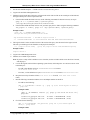
2.3.3.2 Switch CLI Overview
Description
Documentation
When to Use
Host
How to access
The Switch Command Line Interface is a non-GUI method for configuring switches and
querying state. It is also used to access the embedded Subnet Manager.
Switch Users Guide
After the configuration setup has been performed, the user will probably only use the CLI chassis
viewer as part of diagnostics after the Fabric Viewer or Fast Fabric tools have been employed.
However, using CSM/MS dsh or Expect, remote scripts can access the CLI for creating
customized monitoring and management scripts.
Switch chassis
▪
Telnet or ssh to the switch using its IP-address on the cluster VLAN.
▪
Fast Fabric Toolset
▪
dsh from the CSM/MS.
▪
Laptop connected to the RS/232 port
© Copyright IBM Corp. 2008 (7/22/08)
29 of 238
IBM System p HPC Clusters Fabric Guide using InfiniBand Hardware
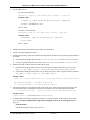
2.3.3.3 Fabric Manager Overview
Description
The fabric manager performs these basic operations:
- Discovers fabric devices
- Configures the fabric
- Monitors the fabric
- Reconfigures the fabric on failure
- Reports problems
The fabric manager has several management interfaces that are used to manage an InfiniBand
network. These include the baseboard manager, performance manager, Subnet Manager, and
fabric executive. All but the fabric executive are described in the InfiniBand architecture. The
fabric executive is there to provide an interface between the Fabric Viewer and the other
managers. Each of these managers is required to fully manage a single subnet. If you have a
host-based fabric manager, there will be up to 4 fabric managers on the Fabric Manager Server.
Configuration parameters for each of the managers for each instance of fabric manager must be
considered. There are many parameters, but only a few will typically vary from default.
A more detailed description of fabric management is available in the InfiniBand standard
specification and vendor documentation.
Documentation
When to Use
QLogic Fabric Manager Users Guide; InfiniBand standard specification
Fabric management must be enabled to manage the network and pass data. You use the Chassis
Viewer, CLI, or Fabric Viewer to interact with the fabric manager.
Host
How to access
-
Host-based is on the Fabric Management Server
-
Embedded is on the Switch
▪
You may access the Fabric Manager functions from CSM by issuing remote commands via
dsh to the Fabric Management Server or switch on which the embedded fabric manager is
running. You can access many instances at once using dsh.
▪
For host-based fabric managers, log-on to the Fabric Management Server.
▪
For embedded fabric managers, use the Chassis Viewer, switch CLI, Fast Fabric Toolset, or
Fabric Viewer to interact with the fabric manager.
© Copyright IBM Corp. 2008 (7/22/08)
30 of 238
IBM System p HPC Clusters Fabric Guide using InfiniBand Hardware
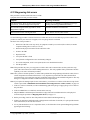
2.3.3.4 Fast Fabric Toolset Overview
Description
Fast Fabric tools are a set of scripts that interface with switches and the various managers to
help quickly interface with many switches and managers at once and distill out useful pieces of
status/information. Additionally, Health check tools have been developed to help the user
identify fabric error states and also unforeseen changes from baseline configuration. They are
run from a central server called the Fabric Management Server.
Note that these tools were developed to also help manage nodes running the QLogic host stack.
The set of functions that do this are not to be used with an IBM system p HPC Cluster, because
CSM is used for systems that are managed in these clusters.
Documentation
When to Use
Host
How to access
Fast Fabric Toolset Users Guide
These should be used during install to look for problems. These can also be used for health
checks when performance degradation is observed.
Fabric Management Server
-
Telnet or ssh to the Fabric Management Server.
-
If you set up the server that is running the Fast Fabric Tools as a managed device, you can
dsh commands to it from CSM.
2.3.3.5 CSM Overview
Description
Documentation
When to Use
Cluster Systems Management. CSM is used by the system admin to monitor and manage the
cluster.
CSM Planning and Install Guide; CSM Administration Guide.
Use this to monitor remote logs from the switches and Fabric Management Servers and to
remotely execute commands on the switches and Fabric Management Servers.
After configuring the switches’ and Fabric Management Servers’ IP-addresses, remote
syslogging and creating them as devices, CSM can be used to monitor for switch events, and
dsh to their CLI.
Host
How to access
CSM Management Server
Use CLI or GUI on the CSM Management Server.
© Copyright IBM Corp. 2008 (7/22/08)
31 of 238
IBM System p HPC Clusters Fabric Guide using InfiniBand Hardware
2.3.3.6 HMC Overview
Description
Documentation
When to Use
Host
How to access
Hardware Management Console. Each HMC is assigned management of a group of servers. If
there is more than one HMC in a cluster, this is accomplished by using the Cluster Ready
Hardware Server on the CSM/MS. This is not intended to be a complete description of the
HMC.
HMC Users Guide
To set up and manage LPARs, including HCA virtualization. To access Service Focal Point for
HCA and server reported hardware events. To control the server hardware.
HMC
Go to the HMC console near the machines; there’s generally a single keyboard and monitor
with a console switch to access multiple HMCs in a rack (should there need to be multiple
HMCs).
Or, you canaccess the HMC via a supported web browser on a remote server that can reach the
HMC..
2.3.3.7 FSP Overview
Description
Flexible Service Processor for the server.
When to Use: How to Access:
Required Connectivity: CSM and the managing HMC must be able to communicate with the
FSP over the service VLAN. For machine type 9125 servers, this connectivity is facilitated via
an internal hardware virtual local area network (VLAN) within the frame, which connects to the
service VLAN.
Documentation
When to Use
Host
How to access
IBM system Users Guide
The FSP is in the background most of the time and the HMC and CSM provide the information.
It is sometimes accessed under direction from engineering.
IBM system
This is primarily used by service personnel. Direct access is rarely required, and is done under
direction from engineering using the ASMI screens. Otherwise, CSM and the HMC are used to
communicate with the FSP.
2.3.3.8 NTP Overview
Description
Documentation
When to Use
Host
How to access
This is used to keep the switches and management servers time of day clocks in sync. It is
extremely important to do this for the sake of being able to correlate events in time.
NTP Users Guide
Set this up during installation.
NTP Server
The admin would access this by logging onto the box on which the NTP server is running. This
is done for configuration and maintenance. Normally, this is just a background application.
© Copyright IBM Corp. 2008 (7/22/08)
32 of 238
IBM System p HPC Clusters Fabric Guide using InfiniBand Hardware
2.3.3.9 Fabric Viewer Overview
Description
The Fabric Viewer is a user interface to access the Fabric Management tools on the various
subnets. It is a Linux or Windows application.
The Fabric Viewer must be able to connect to the cluster VLAN to connect to the switches. It
must also connect to the Subnet Manager hosts via the same cluster VLAN.
Documentation
When to Use
Host
How to access
QLogic Fabric Viewer Users Guide
After you have setup the switch for communication to the Fabric Viewer this can be used as the
main point for queries and interaction with the switches. You will also use this to update the
switch code simultaneously to multiple switches in the cluster. You will also use this during
install time to set up Email notification for link status changes and SM and EM communication
status changes.
Any Linux or Windows host. Typically, this would be:
-
Fabric Management Server
-
Admin or operator workstation
Start the GUI on the server on which you install it, or use a remote window access to bring it up.
(VNC is an example)
2.3.3.10 eMail Notifications Overview
Description
A subset of events can be enabled to trigger an email from the Fabric Viewer. These are link up
and down and communication issues between the Fabric Viewer and parts of the fabric
manager.
Typically Fabric Viewer is used interactively and shutdown after a session. This would prevent
the ability to effectively use eMail notification. If you wish to use this function, you must have a
copy of Fabric Viewer running continuously; for example, on the Fabric Management Server.
Documentation
When to Use
Host
How to access
Fabric Viewer Users Guide
Set up during installation so that you can be notified of events as they occur.
Wherever Fabric Viewer is running.
This setup is done on the Fabric Viewer. The email is accessed from wherever you have
directed the Fabric Viewer to send the email notifications.
2.3.3.11 Server Operating System Overview
Description
Documentation
When to Use
Host
How to access
The operating system is the interface for the device drivers.
Operating System Users Guide
To query the state of the HCAs with respect to availability to applications.
IBM system
dsh from CSM, or telnet/ssh into the LPAR
© Copyright IBM Corp. 2008 (7/22/08)
33 of 238
IBM System p HPC Clusters Fabric Guide using InfiniBand Hardware
2.3.3.12 Management Subsystem Networks
All of the devices in the management subsystem are connected to at least two networks over which their applications
must communicate. Typically, the site will also connect key servers to a local network to provide remote access for
managing the cluster. The networks are:
Service VLAN
The service VLAN is a private Ethernet network which provides connectivity between
the FSPs, BPAs, CSM/MS, and the HMCs to facilitate hardware control. CSM
documentation refers to this as service VLAN, service VLAN, or management VLAN.
Cluster VLAN
The cluster VLAN (or network) is an Ethernet network, (public or private) which gives
CSM access to the operating systems. It is also used for access to InfiniBand switches
and fabric management servers. CSM documentation refers to this as the cluster VLAN.
Note: The switch vendor documentation will refer to this as the service VLAN, or
possibly the management network.
Public Network
Internal Hardware
VLAN
A local site Ethernet network. Typically this will be attached to the CSM/MS and Fabric
Management Server. Some sites may choose to put the cluster VLAN on the public
network. Refer to CSM installation and planning documentation to consider the
implications of combining these networks.
This is a virtual local area network (VLAN) within a frame of 9125 servers. It
concentrates all server FSP connections and the BPH connections onto an internal
ethernet hub, which provides a single connection to the service VLAN, which is external
to the frame.
© Copyright IBM Corp. 2008 (7/22/08)
34 of 238
IBM System p HPC Clusters Fabric Guide using InfiniBand Hardware
2.3.4 Vendor log flow to CSM event management
One of the important points of integration for vendor and IBM management subsystems is log flow from the
vendor’s management applications to CSM event management. This provides a consolidated logging point in the
cluster. The flow of log information is illustrated in Figure 6: Vendor Log Flow to CSM Event Management, on
page 35. For it to work, you have to set up remote logging and CSM Event Management with the Fabric
Management Server and the switches as in Setup Remote Logging, on page 108.
“Remote Logging Enabled” and “CSM Event Management Enabled” are indicated in the figure where these
functions must be enabled for the flow to work.
Switch X
CSM Management Server
Subnet
Manager
Ch assis
Manager
/var/log/csm/syslog.fabric.info
Switch
Log
Remote Logging Enabled
Remote
Logging
Enabled
Fabric Management
Server
syslogd
Remote Logging Enabled
/var/log/csm/syslog.fabric.notices
CSM Event Management Enabled
Subnet
Manager
Syslog
/var/log/messages
CSM Event
Management
/var/log/csm/errorlog/[CSM/MS hostname]
Figure 6: Vendor Log Flow to CSM Event Management
© Copyright IBM Corp. 2008 (7/22/08)
35 of 238
Auditlog
IBM System p HPC Clusters Fabric Guide using InfiniBand Hardware
2.4 Supported components in an HPC cluster
See IBM Clusters with the InfiniBand Switch web-site for latest details.
The following table indicates the components/units that are supported in an HPC cluster.
Component Type
Servers
-
POWER6
Component
Model/Feature or minimum
level
2U high-end server
9125-F2A
High volume server 4U high
8204-E8A
8203-E4A
Blade Server
7988J22
AIX 5.3L(TM)
Version 5.3 with the 5300-08
Technology Level with Service
Pack 2
O/S
Linux SLES
SLES 10 SP2 kernel Level
2.6.16.60-0.14-ppc64 with
Service Pack 2 InfiniBand Device
Driver
Switch
QLogic
9024, 9040, 9080, 9140, 9240
IBM GX+ HCA for 9125-F2A
IBM GX HCAs
IBM GX HCA for 8204-E8A and
8203-E4A
JS22 HCA*
Mellanox 4x Connect-X HCA
8258
JS22 Pass-thru module*
Voltaire High Performance
InfiniBand Pass-Through Module
for IBM BladeCenter
3216
Cable
CX4 to CX4
QSFP to CX4
Management Node for InfiniBand
fabric
IBM system x 3550 (1U high)
7978AC1
IBM system x 3650 (2U high)
7979AC1
HCA for Management Node
QLogic Dual-Port 4X DDR
InfiniBand PCI-E HCA
Fabric Manager
QLogic Host-based Fabric
Manager (Embedded not
recommended)
4.2.1.1.1
Quicksilver/InfiniServ host stack
with Fast Fabric
QLogic host stack and Fast
Fabric toolset
4.2.0.2.1
Switch firmware
QLogic firmware for the switch
4.2.1.1.1
AIX
1.7.0.13 with APAR IZ23836
Linux
1.7.0.13 with APAR IZ23836
HMC
V7R3.3.0 HMC Build level
20080518.1 MH01105_0519
CSM
HMC
© Copyright IBM Corp. 2008 (7/22/08)
36 of 238
IBM System p HPC Clusters Fabric Guide using InfiniBand Hardware
3.0 Cluster Planning
Plan a cluster that leverages InfiniBand technologies for the communications fabric. This section covers the key
elements of the planning process, and helps you organize existing, detailed planning information.
When planning a cluster with an InfiniBand network, you bring together many different devices and management
tools to form a cluster. Major components to consider are:
•
•
•
•
•
•
•
•
•
•
Servers
I/O devices
InfiniBand network devices
Frames (racks)
Service VLAN, including:
o HMCs
o Ethernet devices
o Cluster Systems Management (CSM) Server (for multiple HMC environments)
Management Network, including:
o Cluster Systems Management (CSM) Server
o Servers to provide operating system access from CSM
o InfiniBand switches
o Fabric Managemetn Server
o AIX Network Installation Management (NIM) server (for servers with no removable media)
o Linux distribution server (for servers with no removable media)
System management applications, including:
o HMC
o CSM
o Fabric Manager
o Other QLogic management tools
Fast Fabric Toolset, Fabric Viewer and Chassis Viewer
Physical characteristics such as weight and dimensions
Electrical characteristics
Cooling characteristics
Information resources, on page 14, is intended to help you find references for many required documents and other
Internet resources that will help you plan your cluster. It is not an exhaustive list of the documents that you will
need, but it should provide a good launch point for gathering required information.
Use Planning Overview, on page 37 as a roadmap through the planning procedures. Read through the Planning
Overview once without traversing any of the links to other sections so that you can understand the overall planning
strategy. Then, go back and follow the links that direct you through the different procedures.
The Planning Overview, the planning procedures and the sub-procedures are arranged under headings in a
sequential order for a new cluster installation. If you are performing an installation other than that for a new cluster,
you may need to pick and choose which procedures to use, but you should do so in the order in which they appear in
the Planning Overview. For a new cluster install, you can read through to the end of the Cluster Planning chapter.
If you are using the links in Planning Overview, on page 37, note when a planning procedure ends so that you
know when to return to the Planning Overview, on page 37. The end of each major planning procedure will be
indicated by “[planning procedure name] ends here”.
3.1 Planning Overview
Read through this Planning Overview section once before traversing any links so that you can understand the
overall planning strategy. Then, go back and follow the links that direct you rhrough the different procedures.
Do the following to plan your cluster:
1.
When planning your cluster, you need to first gather and review the planning and installation information
for the various components in the cluster. Refer to Information resources, on page 14, as a starting point
for where to obtain such information. Because this document provides supplemental information with
© Copyright IBM Corp. 2008 (7/22/08)
37 of 238
IBM System p HPC Clusters Fabric Guide using InfiniBand Hardware
respect to clustered computing with an InfiniBand network, you must understand all of the planning
information for the individual components before proceeding with this planning overview.
2.
Review Planning checklist, on page 69, which can help you keep track of which planning steps that you
have completed.
3.
Review Required Level of support, firmware and devices, on page 39, to understand the minimal level
of software and firmware required to support clustering with an InfiniBand network.
4.
Review the planning resources for the individual servers that you wish to use in your cluster; see Server
Planning, on page 40.
5.
Review Planning InfiniBand network cabling and configuration, on page 40 to understand the network
devices and configuration. The planning information will address:
6.
6
-
Planning QLogic InfiniBand switch configuration, on page 41.
-
Planning an IBM GX HCA configuration, on page 43. For vendor HCA planning use the vendor
documentation.
Review the information in Management Subsystem Planning, on page 45. The planning information will
address:
6
-
When you need Cluster Systems Management (CSM).
-
HMCs in a cluster.
-
AIX NIM and Linux distribution servers.
-
Planning CSM as your Systems Management Application, on page 46.
-
Planning for QLogic Fabric Management Applications, on page 47.
-
Planning for Fabric Management Server, on page 55.
-
Planning Event Monitoring with QLogic and CSM, on page 56.
-
Planning Remote Command Execution with QLogic from the CSM/MS, on page 57.
7.
After you understand the various devices in your cluster, review Frame Planning, on page 58, as a final
step to assure that you have properly planned where to put devices in your cluster.
8.
After you understand the basic concepts for planning the cluster, review the high-level installation flow
information in Planning Installation Flow, on page 59. There are hints about planning your installation,
and also guidelines to help you to coordinate between you (customer) and IBM Service Representative
Responsibilities and vendor responsibilities during the installation process.
6
9.
Consider special circumstances such as whether you are configuring a cluster for High Performance
Computing (HPC) Message Passing Interface (MPI) applications, in which case, you should refer
Important information for planning an HPC MPI configuration, on page 66.
10. For some more hints and tips on installation planning, refer to Planning Aids, on page 68.
6
If you have completed all of the above steps, you can plan in more detail using the planning worksheets provided in
Planning worksheets, on page 70.
6
When you are ready to install the components with which you will build your cluster, review any information in
readme files and online information related to the software and firmware to ensure that you have the latest
information and the latest supported levels of firmware.
If this is the first time you have read the Planning Overview section and you understand the overall intent of the
planning tasks, go back to the beginning and start traversing the links and cross-references to get to the details.
Planning Overview ends here.
© Copyright IBM Corp. 2008 (7/22/08)
38 of 238
IBM System p HPC Clusters Fabric Guide using InfiniBand Hardware
3.2 Required Level of support, firmware and devices
The following tables provide the minimum requirements necessary to support InfiniBand network clustering.
Note:
For the most recent updates to this information, see the following Facts and Features Web site,
http://www.ibm.com/servers/eserver/clusters/hardware/factsfeatures.html
Table 2. Verified and approved hardware associated with an IBM System p (POWER6) cluster with an
InfiniBand network
Device
Model or Feature
Servers
POWER6
9125-F2A
IBM 8204 System p 550 4U rack-mount server (8204E8A)
IBM 8203 System p 520 4U rack-mount servers (8203E4A)
Switches
QLogic models
9024
9040
9080
9120
9240
Host Channel Adapters (HCAs)
The feature code is dependent on server. Order one or
more InfiniBand GX, Dual-port HCA per server that
requires connectivity to InfiniBand networks. The
maximum number of HCAs allowed depends on the
server model.
Fabric Management Server
IBM system x 3550 or 3650
SLES 10 Linux
QLogic HCAs
Note:
* HPC proven and validated to work in an IBM HPC cluster.
** For approved IBM System p POWER6(TM) and eServer(TM) p5 InfiniBand configurations, see the Facts and
Features Web site, http://www.ibm.com/servers/eserver/clusters/hardware/factsfeatures.html
Table 3. Minimum levels of software and firmware associated with an InfiniBand cluster
Software
Minimum Level
AIX(R)
AIX 5L(TM) Version 5.3 with the 5300-08 Technology
Level with Service Pack 2
SUSE Linux Enterprise Server 10
SUSE Linux(R) Enterprise Server 10 SP2 with
© Copyright IBM Corp. 2008 (7/22/08)
39 of 238
IBM System p HPC Clusters Fabric Guide using InfiniBand Hardware
IBMInfiniBand GX+ HCA driver and OpenIB Gen2
Stack available in SLES10SP2-AS
Hardware Management Console
V7R3.3
System firmware level for System pOWER 6(TM)
InfiniBand switch firmware
QLogic 4.2.1.1.1
Fabric Manager
QLogic 4.2.1.1.1
Fast Fabric Toolset
QLogic Host stack for Fabric Management Server
QLogic’s InfiniServ 4.2.0.0.39
For the most recent support information refer to the IBM clusters with the InfiniBand Switch web-site.
Required Level of support, firmware and devices that are needed to support HPC cluster with an InfiniBand network
ends here.
3.3 Server Planning
Server planning relative to the fabric will involve deciding:
-
The number of each type of server you require.
-
The type of operating system(s) running on each server
-
The number and type of HCAs that are required in each server
-
Which types of HCAs are required in each server
-
Addressing for the InfiniBand network (consider IP subnet addressing restriction, on page 44)
-
Addressing for the service VLAN for FSP access from CSM and HMCs
-
Addressing for the cluster VLAN for operating system access from CSM
Note: Logical Partitioning is generally not done in HPC Clusters.
Along with server planning documentation, you should use Server planning worksheet, on page 73, as a planning
aid. Finally, it is a good idea to review server installation documentation to help plan for the installation. When you
know the frames in which you wish to place your servers, record the information in the Frame and rack planning
worksheet, on page 72
3.4 Planning InfiniBand network cabling and configuration
Before you plan your InfiniBand network cabling, review the hardware installation and cabling information for your
vendor switch. Contact QLogic support for details and documentatio006E. Search for the documentation regarding
the 9000 Series InfiniBand switches.
While planning your cabling, keep in mind the IBM server and frame physical characteristics that affect cable
planning. In particular:
•
•
•
•
Consider the server height and placement in the frame to plan for cable routing within the frame. This
affects the distance of the HCA connectors from the top of the raised floor.
Consider routing to the cable entrance of a frame
Consider cable routing within a frame, especially with respect to bend radius and cable management.
Consider floor depth
© Copyright IBM Corp. 2008 (7/22/08)
40 of 238
IBM System p HPC Clusters Fabric Guide using InfiniBand Hardware
•
Remember to plan for connections from the Fabric Management Servers; see Planning for Fabric
Management Server, on page 55.
If you are using 12x HCAs (for example in a 9119-590 server), you should review Planning 12x HCA connections,
on page 67, to understand the unique cabling and configuration requirements when using these adapters with the
available 4x switches.
Record the cable connection information planned here in the QLogic Switch planning worksheet, on page 74, for
switch port connections and in a Server planning worksheet, on page 73,for HCA port connections.
7
7
Planning InfiniBand network cabling and configuration ends here.
3.4.1 Planning QLogic InfiniBand switch configuration
Most QLogic switch planning should be done using QLogic planning resources including general planning guides
and planning guides specific to the model being installed.
QLogic switches require some custom configuration to work well in an IBM System p HPC cluster. The
configuration settings that need to be planned are:
•
•
•
•
•
•
•
IP-addressing on the cluster VLAN should be configured static. The address should be planned and
recorded.
Chassis MTU value
Switch name
12x cabling considerations
Disable telnet in favor of ssh access to the switches
Remote logging destination (CSM/MS is recommended)
New chassis passwords
The IP-addressing a QLogic switch will have on the management Ethernet network is configured for static
addressing. These addresses are associated with the switch management function. Important QLogic management
function concepts are:
-
The 9024 switches have a single address associated with its management Ethernet connection.
-
All other QLogic switches have one or more managed spine cards per chassis. If you want backup
capability for the management subsystem, you must have more than one managed spine in a chassis.
-
Each managed spine gets its own address so that it can be addressed directly.
-
Each switch chassis also gets a management Ethernet address that is assumed by the master
management spine. This allows you to use a single address to query the chassis regardless of which
spine is master. To setup management parameters (like which spine is master) each managed spine
must be addressed separately. H
-
The QLogic 9240 switch chassis is broken into two managed hemispheres. Therefore, you will require
a master and backup managed spine within each hemisphere. This will be a total of four managed
spines.
-
o
Each managed spine gets its own management Ethernet address.
o
The chassis will have two management Ethernet addresses. One for each hemisphere.
o
Review the 9240 Users Guide to assure that you understand which spine slots are used for
managed spines.
The total number of management Ethernet addresses is driven by the switch model:
o
9024 has one address
o
9240 has from 4 (no redundancy) to 6(full redundancy) addresses
© Copyright IBM Corp. 2008 (7/22/08)
41 of 238
IBM System p HPC Clusters Fabric Guide using InfiniBand Hardware
o
All other models have from 2 (no redundancy) to 3 addresses.
For topology and cabling, see Planning InfiniBand network cabling and configuration, on page 40.
-
Chassis Maximum Transfer Unit (MTU) must be set to an appropriate value for each switch in a cluster. For more
information on this see Planning MTU, on page 42.
For each subnet, you will need to plan a different GID-prefix; see Planning GID Prefixes, on page 43.
You should assign a name to each switch. It should be something that indicates its physical location on a machine
floor. You may wish to include the frame and slot in which it resides. The key is a consistent naming convention that
is meaningful to you and your service provider.
If you have a 4x switch connecting to 12x HCA, you will require a12x to 4x width exchanger cables For more
details, see Planning 12x HCA connections, on page 67.
7
While passwordless ssh is recommended from CSM/MS and the Fabric Mangement Server to the switch chassis, it
is also recommended that you change the switch chassis default password early in the installation process. For Fast
Fabric Toolset functionality, all of the switch chassis passwords should be the same.
Consolidating switch chassis logs and embedded Subnet Manager logs into a central location is highly
recommended. Because CSM is also recommended as the Systems Management application, the CSM/MS is
recommended to be the recipient of the remote logs from the switch. You can only direct logs from a switch to a
single remote host (CSM/MS). Setup Remote Logging, on page 108, is the procedure used for setting up remote
logging in the cluster.
The information planned here should be recorded in a QLogic Switch planning worksheets, on page 74.
Planning QLogic InfiniBand switch configuration ends here.
3.4.1.1 Planning MTU
Depending on your configuration there are different recommended Maximum Transfer Units (MTUs).
The following, Table 8: MTU Settings, on page 42, indicates the MTU values that MPI and IP require for
maximum performance.
Cluster Type indicates the type of cluster with respect the generation and type of HCAs used. You either have a
Homogeneous cluster based on all HCAs being the same generation and type, or a Heterogeneous cluster based on
the HCAs being a mix of generations and types. Cluster Composition by HCA indicates the actual generation and
type of HCAs being used in the cluster.
Switch and Subnet Manager (SM) Settings indicates the settings for the switch chassis and Subnet Manager that are
recommended. The Chassis MTU is used by the switch chassis and applies to the entire chassis, and should be set
the same for all chassis in the cluster. Furthermore, Chassis MTU affects MPI. The Broadcast MTU is set by the
Subnet Manager and affects IP. It is part of the broadcast group settings. It should be the same for all broadcast
groups.
MPI MTU indicates the setting that MPI requires for the configuration. IP MTU indicates the setting that IP
requires. MPI MTU and IP MTU are included to help understand the settings indicated in the Switch and SM
Settings column. The BC rate is the broadcast MTU rate setting, which will either be 10GB (3) or 20GB (6). SDR
switches run at 10GB and DDR switches run at 20GB.
The number in parentheses indicates the parameter setting in the firmware and SM which represents that setting.
Table 8: MTU Settings
Cluster Type
Homogeneous
HCAs
Cluster Composition by
HCA
System p5 GX HCA only
© Copyright IBM Corp. 2008 (7/22/08)
Switch and SM Settings
MPI MTU
IP MTU
Chassis MTU=2K (4)
Broadcast MTU=2K (5)
BC Rate = 10GB (3)
2K
2K
42 of 238
IBM System p HPC Clusters Fabric Guide using InfiniBand Hardware
Cluster Type
Homogeneous
HCAs
Cluster Composition by
HCA
System p (POWER6) GX
HCA only in 9125-F2A
Homogeneous
HCAs
POWER6 GX HCA in
8204-E8A or 8203-E4A.
Homogeneous
HCAs
ConnectX HCA only
Heterogeneous
HCAs
GX HCA in 9125-F2A
(compute servers) and GX
HCA in 8204-E8A or
8203-E4A (GPFS(TM)
servers)
POWER6 GX HCA
(compute) & P5 HCA
(GPFS(TM) servers)
ConnectX HCA (compute)
& P5 HCA (GPFS servers)
Heterogeneous
HCAs
Heterogeneous
HCAs
Switch and SM Settings
MPI MTU
IP MTU
Chassis MTU=4K (5)
Broadcast MTU=4K (5)
BC Rate = 10GB (3) for SDR
switches, or 20GB (6) for DDR
switches.
Chassis MTU=2K (4)
Broadcast MTU=2K (4)
BC Rate = 10GB (3) for SDR
switches, or 20GB (6) for DDR
switches
Chassis MTU=2K (4)
Broadcast MTU=2K (4)
BC Rate = 10GB (3) for SDR
switches, or 20GB (6) for DDR
switches
Chassis MTU=4K (5)
Broadcast MTU=2K (4)
BC Rate = 10GB (3)
4K
4K
2K
2K
2K
2K
Between
compute
only 1 = 4K
2K
Chassis MTU=4K (5)
Broadcast MTU=2K (4)
BC Rate = 10GB (3)
Chassis MTU=2K (4)
Broadcast MTU=2K (4)
BC Rate = 10GB (3)
Between
POWER6
only = 4K
2K
2K
2K
The configuration settings for fabric managers planned here should be recorded in the QLogic Fabric Management
worksheets, on page 79.
The configuration settings for switches planned here should be recorded in the QLogic Switch planning
worksheets, on page 74.
Planning MTU ends here.
3.4.1.2 Planning GID Prefixes
This section briefly describes why and how to plan for fabric GID prefixes in an IBM System p HPC Cluster.
Each subnet in the InfiniBand network must be assigned a GID-prefix, which will be used to identify the subnet for
addressing purposes. The GID-prefix is an arbitrary assignment with a format of: xx:xx:xx:xx:xx:xx:xx:xx. For
example: FE:80:00:00:00:00:00:01. The default is FE:80:00:00:00:00:00:00.
The GID-prefix is set by the Subnet Manager. Therefore, each instance of the Subnet Manager must be configured
with the appropriate GID-prefix. On any given subnet, all instances of the Subnet Manager (master and backups)
must be configured with the same GID-prefix.
Planning GID Prefixes ends here.
3.4.2 Planning an IBM GX HCA configuration
An IBM GX host channel adapter (HCA) needs to have certain configuration settings to work in an IBM POWER
InfiniBand cluster. These are:
1
IPoIB performance between compute nodes may be degraded because they are bound by the 2K MTU.
© Copyright IBM Corp. 2008 (7/22/08)
43 of 238
IBM System p HPC Clusters Fabric Guide using InfiniBand Hardware
•
•
•
GUID index
Capability
GID-prefix for each port of an HCA
InfiniBand subnet IP addressing based on subnet restrictions (see IP subnet addressing restriction, on page
44)Each physical InfiniBand HCA contains a set of 16 globally unique IDs (GUIDs) than can be assigned to
partition profiles. These are used to address logical HCA (LHCA) resources on an HCA. You can assign multiple
GUIDs to each profile, but you can assign only one GUID from each HCA to each partition profile. Each GUID can
be used by only one logical partition at a time. You can create multiple partition profiles with the same GUID, but
only one of those partition profiles can be activated at a time.
The GUID index is used to choose one of the 16 GUIDs available for an HCA. It can be any number from 1 through
16. Quite often you will assign a GUID index based on which LPAR and profile you are configuring. For example,
on each server you may have 4 partitions.The first paritition on each server might use a GUID index of 1, and the
second would use a GUID index of 2, to the third would use a GUID index of 3, and the fourth using a GUID index
of 4.
The Capability setting is used to indicate the level of sharing to be done. This can be one of the following:
1.
2.
3.
4.
Low
Medium
High
Dedicated
While the GID-prefix for a port is not something that you explicitly set, it is important to understand the subnet to
which a port attaches. This is determined by the switch to which the HCA port is connected. The GID-prefix is
actually configured for the switch. See Planning GID Prefixes, on page 43.
7
Additional information on partition profiles is available in the Information Center:
http://publib.boulder.ibm.com/infocenter/eserver/v1r3s/topic/iphat/iphatparprofile.htm
The configuration settings planned here should be recorded in a Server planning worksheet, on page 73, which is
used to record HCA configuration information.
Note: 9125-F2A servers with “heavy” I/O planars will have an extra InfiniBand device defined. This is always iba3.
Delete this from the configuration.
Planning an IBM GX HCA configuration ends here.
3.4.2.1 IP subnet addressing restriction
There are restrictions to how you may configure IP subnet addressing in a server attached to an InfiniBand network.
It should be noted that both IP and InfiniBand use the term subnet. These are two distinctly different entities, as you
will see in the following paragraphs.
The IP addresses for the HCA network interfaces must be set up such that no two IP addresses in a given LPAR are
in the same IP subnet. When planning for the IP subnets in the cluster, as many separate IP subnets should be
established as there are IP addresses on a given LPAR.
The subnets should be set up such that all IP addresses in a given IP subnet should be connected to the same
InfiniBand subnet. If there are N network interfaces on each LPAR connected to the same InfiniBand subnet, then N
separate IP subnets should be established.
Note: This IP subnetting limitation does not prevent multiple adapters or ports from being connected to the same
InfiniBand subnet. It is only a statement of how the IP addresses must be configured.
© Copyright IBM Corp. 2008 (7/22/08)
44 of 238
IBM System p HPC Clusters Fabric Guide using InfiniBand Hardware
3.5 Management Subsystem Planning
This section is a summary of the service and cluster VLANs, Hardware Management Console (HMC), Systems
Management application and Server, vendor Fabric Management applications, AIX NIM server and Linux
Distribution server, and pointers to key references in planning the management subsystem. Finally, the frames that
house the management consoles need to be planned.
Customer supplied Ethernet service and cluster VLANs are required to support the InfiniBand cluster computing
environment. The number of Ethernet connections depends on the number of servers, Bulk Power Controllers
(BPCs) in 24-inch frames, InfiniBand switches, and HMCs in the cluster. The Systems Management application and
server, which may include Cluster Ready Hardware Server (CRHS) software would also require a connection to the
service VLAN.
Note: While it is recommended that you have two service VLANs on different subnets to support redundancy in
IBM servers, BPCs, and HMCs, the InfiniBand switches only support a single service VLAN;even though
some InfiniBand switch models have multiple Ethernet connections, these connect to different management
processors and thus should connect to the same Ethernet network.
An HMC may be required to manage the LPARs and to configure the GX bus HCAs in the servers. The maximum
number of servers that can be managed by an HMC is 32. When you go beyond 32 servers, additional HMC’s are
required. See Solutions with the Hardware Management Console in the IBM systems Hardware Information Center.
It is under the Planning > Solutions > Planning for consoles, interfaces, and terminals path.
If you require more than one HMC to manage your cluster servers and switches, you must use Cluster Ready
Hardware Server in Cluster Systems Management (CSM) on a CSM Management Server. Refer to the CSM Install
and Planning Guide. You can also use CSM when you have only one HMC.
If you have a single HMC in the cluster, it is normally configured to be the required DHCP server for the service
VLAN, and the CSM/MS will be the DHCP server for the cluster VLAN. If Cluster Ready Hardware Server
(CRHS) and CSM are being used in the cluster, the CSM Management Server is typically set up as the DHCP server
for the service and cluster VLANs, and CRHS must be configured to recognize the servers, BPAs, HMCs. Refer to
the CSM: Administration Guide.
The servers have connections to the service and cluster VLANs. Refer to CSM documentation for more information
on the cluster VLAN. Refer to the server documentation for more information on connecting to the service VLAN.
In particular, pay attention to:
•
•
The number of service processor connections from the server to the service VLAN
If there is a BPC for the power distribution, as in a 24-inch frame, it may provide a hub for the
processors in the frame, allowing for a single connection per frame to the service VLAN.
After you understand the number of devices and cabling of your service and cluster VLANs, you will need to
consider the device IP-addressing. Here are the key considerations:
1.
2.
3.
4.
Determine the domain addressing and netmasks for the Ethernet networks that you will implement.
Assign static-IP-addresses
a. Assign a static IP-address for HMCs when you are using CSM and Cluster Ready Hardware
Server. This is mandatory when you have multiple HMCs in the cluster.
b. Assign a static IP-address for switches when you are using CSM and Cluster Ready Hardware
Server. This is mandatory when you have multiple HMCs in the cluster.
Determine the DHCP range for each Ethernet subnet.
If you must use CSM and Cluster Ready Hardware Server, the DHCP server is recommended to be on
the CSM Management Server, and all HMCs must have their DHCP server capability disabled.
Otherwise, you are in a single HMC environment where the HMC is the DHCP server for the service
VLAN.
If there are servers in the cluster without removable media (CD or DVD), you will require an AIX NIM server for
System p server diagnostics. If you are using AIX in your partitions, this will also provide NIM service for the
partition. The NIM server will be on the cluster VLAN.
© Copyright IBM Corp. 2008 (7/22/08)
45 of 238
IBM System p HPC Clusters Fabric Guide using InfiniBand Hardware
If there are servers running Linux in your partitions, that do not have removable media (CD or DVD), a Linux
Distribution server is required. The Cluster summary worksheet, on page 71, should be used to record the
information in this section.
Frames/racks need to be planned for the management servers. Consolidate the management servers into the same
rack whenever possible. The following management servers should be considered:
•
HMC
•
CSM management server
•
Fabric management server
•
AIX NIM and Linux distribution servers
•
NTP server
Further management subsystem considerations are:
-
Review the beginning of Management subsystem installation and configuration, on page 95
through Figure 10: Management Subsystem Installation Tasks, on page 97. This is especially
important for helping assign tasks in Installation Coordination Worksheet, on page 65.
-
Planning CSM as your Systems Management Application, on page 46
-
Planning for QLogic Fabric Management Applications, on page 47
-
Planning for Fabric Management Server, on page 55
-
Planning Event Monitoring with QLogic and CSM, on page 56
-
Planning Remote Command Execution with QLogic from the CSM/MS, on page 57
3.5.1 Planning CSM as your Systems Management Application
If you must use Cluster Ready Hardware Server (CRHS) with CSM, the CSM Management Server (CSM/MS) is
typically the DHCP server for the service VLAN. If the cluster VLAN is public or local site network, then it is
possible that another server may be setup as the DHCP server. It is strongly recommended that the CSM
Management Server be a stand-alone server. If you use one of the compute or I/O servers in the cluster for CSM,
the CSM operation might degrade performance for user applications, and it will complicate the installation process
with respect to server setup and discovery on the service VLAN.
It is highly recommended that CSM event management be leveraged in a cluster. In order to do this, you need to
plan for the following:
-
The type of syslogd that you are going to use. At the least, you need to understand the default syslogd that
comes with the operating system on which CSM will run.
-
Whether or not you wish to use tcp or udp as the protocol for transferring syslog entries from the Fabric
Management Server to the CSM/MS. You must use udp if the CSM/MS is using syslog. If the CSM/MS
has syslog-ng installed, you may use tcp for better reliability. The switches only use udp.
-
If syslog-ng is used on the CSM/MS, there will be a src line that controls the ip-addresses and ports over
which syslog-ng will accept logs. The default setup is address “0.0.0.0”, which means “all addresses”. For
added security, you may wish to plan to have a src definition for each switch’s and Fabric Management
Server’s ip-address rather than opening it up to all ip-addresses on the service VLAN. For information on
the format of the src line see Setup Remote Logging, on page 108.
Remote command execution from the CSM/MS to the Fabric Management Servers is especially advantageous when
you have more than one Fabric Management Server in a cluster. For remote command execution to the Fabric
Management Servers, you will need to research how to exchange ssh keys between the Fabric Management Server
and the CSM/MS. This is standard openSSH protocol setup as done in either AIX or Linux.
© Copyright IBM Corp. 2008 (7/22/08)
46 of 238
IBM System p HPC Clusters Fabric Guide using InfiniBand Hardware
If you do not require a CSM Management Server, you might need a server to act as an AIX Network Installation
Manager (NIM) server for eServer diagnostics. This is the case for servers that do not have removable media (CD or
DVD), such as a 575 (9118-575).
Furthermore, if you have servers with no removable media that are running Linux partitions, you may require a
server to act as a Linux distribution server.
If you require both an AIX NIM server and a Linux distribution server, and you choose the same server for both, a
reboot is needed to change between the services. If the AIX NIM server is used only for eServer diagnostics, this
may be acceptable in your environment. However, you should understand that this may prolong a service call if use
of the AIX NIM service is required. For example, the server that might normally act as a Linux distribution server
could have a second boot image to server as the AIX NIM server. If AIX NIM services are required for System p
diagnostics during a service call, the Linux distribution server must be rebooted to the AIX NIM image before
diagnostics can be performed.
The configuration settings planned here should be recorded in the CSM Planning Worksheet, on page 76.
Planning CSM as your Systems Management Application ends here
3.5.2 Planning for QLogic Fabric Management Applications
Plan for QLogic Fabric Management Applications using the following:
1.
Planning Fabric Manager and Fabric Viewer, on page 47.
2.
Planning Fast Fabric Toolset, on page 54.
3.
Planning for Fabric Management Server, on page 55.
3.5.2.1 Planning Fabric Manager and Fabric Viewer
Most details are available in the Fabric Manager and Fabric Viewer Users Guide from QLogic. This section will
highlight important information from a cluster perspective.
The Fabric Viewer may be used as documented by QLogic.
The Fabric Manager has a few key parameters that should be setup in a specific manner for IBM System p HPC
Clusters.
Here are key points to planning your fabric manager in an IBM System p HPC Cluster:
Note: Refer to Figure 7: Typical Fabric Manager Configuration on a single Fabric Management Server,
on page 49, and Figure 8: Typical Fabric Management Server configuration with 8 subnets, on page
50, for illustrations of typical fabric management configurations.
-
IBM has only qualified use of a host-based fabric manager (HFM). The HFM is more typically
referred to as host-based Subnet Manager (HSM), because the Subnet Manager is generally considered
the most important component of the fabric manager.
-
The host for HSM is the Fabric Management Server; see Planning for Fabric Management Server,
on page 55.
-
o
The host requires one HCA port per subnet to be managed by the Subnet Manager.
o
If you have more than 4 subnets in your cluster, you should have 2 hosts actively servicing your
fabrics. To allow for backups, you would require up to 4 hosts to be Fabric Management Servers.
That would be two hosts as primaries and two hosts as backups.
o
Consolidating switch chassis and Subnet Manager logs into a central location is highly
recommended. Because CSM is also recommended as the Systems Management application, the
CSM/MS is recommended to be the recipient of the remote logs from the switch. You can direct
logs from a Fabric Management Server to multiple remote hosts (CSM/MS’s). Setup Remote
Logging, on page 108, is the procedure used for setting up remote logging in the cluster.
Backup Fabric Management Servers are highly recommended for HSM.
© Copyright IBM Corp. 2008 (7/22/08)
47 of 238
IBM System p HPC Clusters Fabric Guide using InfiniBand Hardware
-
At least one unique instance of Fabric Manager to manage each subnet is required.
o
A host-based Fabric Manager instance is associated with a specific HCA and port over which
it will communicate with the subnet which it manages.
o
For example, if you have 4 subnets and one Fabric Management Server, it will have 4
instances of Subnet Manager running on it; one for each subnet. Also, the server must be
attached to all 4 subnets.
o
The Fabric Manager consists of four processes: the subnet manager (SM), the performance
manager (PM), baseboard manager (BM) and fabric executive (FE). For more details, see
Fabric Manager Overview, on page 30, and the QLogic Fabric Manager Users Guide.
o
It is common in the industy for the terms Subnet Manager and Fabric Manager to be used
interchangeably, because the Subnet Manager performs the most vital role in managing the
fabric.
-
The HSM license fee is based on the size of the cluster that it will cover. See vendor documentation
and web-site.
-
Embedded Subnet Manager (ESM) considerations:
o
IBM is not qualifying the embedded Subnet Manager.
o
If you use an embedded Subnet Manager, you may experience performance problems and outages
if the subnet has more than 64 IBM GX/GX+ HCA ports attached to it. This is because of the
limited compute power and memory available to run the embedded Subnet Manager in the switch,
and because the IBM GX/GX+ HCAs also present themselves as multiple logical devices, because
they can be virtualized; see IBM GX/GX+ HCA, on page 21. Considering these restrictions, IBM
recommends that you restrict embedded Subnet Manager use to subnets with only one model 9024
switch in them.
o
If you plan to use the embedded Subnet Manager, you will still require the Fabric Management
Server for the Fast Fabric Toolset; see Planning Fast Fabric Toolset, on page 54. Therefore,
using ESM will not eliminate the need for a Fabric Management Server. The need for a backup
Fabric Management Server will not be as great, but it is still recommended.
o
You may find it simpler to maintain host-based Subnet Manager code than embedded Subnet
Manager code.
o
You must obtain a license for the embedded Subnet Manager. It is keyed to the switch chassis
serial number.
© Copyright IBM Corp. 2008 (7/22/08)
48 of 238
IBM System p HPC Clusters Fabric Guide using InfiniBand Hardware
Fabric Management Server
Fabric Manager 0
SM_0
PM_0
BM_0
FE_0
HCA 1
Fabric Manager 1
Subnet 1
Port 1
Port 2
SM_1
PM_1
BM_1
FE_1
Subnet 2
Fabric Manager 2
SM_2
PM_2
BM_2
FE_2
Fabric Manager 3
Subnet 3
HCA 2
Port 1
Port 2
Subnet 4
SM_3
PM_3
BM_3
FE_3
Note: In the /etc/sysconfig/iview_fm.config file, HCA1 would correspond to SM_X_device=0, and
HCA2 would correspond to SM_X_device=1
Figure 7: Typical Fabric Manager Configuration on a single Fabric Management Server
© Copyright IBM Corp. 2008 (7/22/08)
49 of 238
IBM System p HPC Clusters Fabric Guide using InfiniBand Hardware
Fabric Management Server 1
Fabric Manager 0
Priority 1
Primary FMs
for
subnets 1 to 4
(priority=1)
HCA 1
Port 1
Fabric Manager 1
Priority 1
Port 2
Fabric Manager 2
Priority 1
HCA 2
Fabric Manager 3
Priority 1
Port 2
Subnet 1
Port 1
Subnet 2
Fabric Management Server 2
Backup FMs
for
subnets 1 to 4
(priority=0)
Fabric Manager 0
Priority 0
HCA 1
Subnet 3
Port 1
Fabric Manager 1
Priority 0
Port 2
Fabric Manager 2
Priority 0
HCA 2
Fabric Manager 3
Priority 0
Port 2
Port 1
Subnet 4
Fabric Management Server 3
Primary FMs
for
subnets 5 to 8
(priority=1)
Fabric Manager 0
Priority 1
HCA 1
Port 1
Fabric Manager 1
Priority 1
Port 2
Fabric Manager 2
Priority 1
HCA 2
Fabric Manager 3
Priority 1
Port 2
Subnet 5
Port 1
Subnet 6
Fabric Management Server 4
Backup FMs
for
subnets 5 to 8
(priority=0)
Fabric Manager 0
Priority 0
HCA 1
Subnet 7
Port 1
Fabric Manager 1
Priority 0
Port 2
Fabric Manager 2
Priority 0
HCA 2
Fabric Manager 3
Priority 0
Port 2
Subnet 8
Port 1
Figure 8: Typical Fabric Management Server configuration with 8 subnets
© Copyright IBM Corp. 2008 (7/22/08)
50 of 238
IBM System p HPC Clusters Fabric Guide using InfiniBand Hardware
The key parameters for which to plan for the Fabric Manager are:
Note: If a parameter applies to only a certain component of the fabric manager that will be noted below.
Otherwise, you must specify that parameter for each component of each instance of the fabric manager on
the Fabric Management Server. Components of the fabric manager are: subnet manager (SM),
performance manager (PM), baseboard manager (BM), and fabric executive (FE).
-
Plan a GID prefix for each subnet. Each subnet requires a different GID prefix, which will be set by
the Subnet Manager. The default is 0xfe80000000000000. This is for the subnet manager only.
-
LMC = 2 to allow for 4 LIDs. This is important for IBM MPI performance. This is for the subnet
manager only.
-
For each Fabric Management Server, plan which instance of the fabric manager will be used to manage
each subnet. Instances are numbered from 0 to 3 on a single Fabric Management Server. For example,
if a single Fabric Management server is managing 4 subnets, you will typically have instance 0 manage
the first subnet, instance 1 manage the second subnet, instance 2 manage the third subnet and instance
3 manage the fourth subnet. All components under a particular fabric manager instance are referenced
using the same instance. For example, fabric manager instance 0, will have SM_0, PM_0, BM_0, and
FE_0.
-
For each Fabric Management Server, plan which HCA and HCA port on each will connect which
subnet. You will need this to point each fabric management instance to the correct HCA and HCA port
so that it will manage the correct subnet. This is specified individually for each component. However,
it should be the same for each component in each instance of fabric manager. Otherwise, you could
have the SM component of the fabric manager 0 manage one subnet and the PM component of the
fabric manager 0 managing another subnet. This would make it very confusing to try to understand
how things are setup. Typically, instance 0 will manage the first subnet, which will typically be on the
first port of the first HCA, and instance 1 will manage the second subnet, which will typically be on
the second port of the first HCA, and instance 2 will manage the third subnet, which will typically be
on the first port of the second HCA, and instance 3 will manage the fourth subnet, which will typically
be on the second port of the second HCA.
-
Plan for a backup Fabric Manager for each subnet.
o
Assign priorities for each Subnet Manager instance so that you have a master and backup
takeover scheme. The master has the highest priority number. The lowest priority is 0 and the
highest priority is 15. Typically, you will only have a single backup for each subnet, so you
will typically use priority number 1 for the master, and priority number 0 for the backup.
o
This is specified individually for each component, but it should be the same for each instance.
For example, if SM_0_priority=1, PM_0_priority=1, BM_0_priority=1, FE_0_priority=1.
While it is technically possible to assign different priorities to different components within the
same instance of a fabric manager, it would be difficult to keep track of where the master
instances were for each component on each subnet.
-
Plan for the MTU using the rules found in Planning MTU, on page 42. This is for the subnet manager
only.
-
There are other parameters that can be configured for the Subnet Manager. However, the defaults are
typically chosen for those. Further details can be found in the QLogic Fabric Manager Users Guide.
Example setup of host-based fabric manager:
The following is a set of example entries from an iview_fm.config file on a fabric management server,
which manages two subnets, where the fabric manager is the primary one, as indicated by a priority=1.
These entries are found throughout the file in the startup section, and each of the manager sections in
each of the instance sections. In this case, instance 0 manages subnet 1 and instance 1 manages subnet 2
and instance 2 manages subnet 3 and instance 3 manages subnet 4.
© Copyright IBM Corp. 2008 (7/22/08)
51 of 238
IBM System p HPC Clusters Fabric Guide using InfiniBand Hardware
Note: Comments in this example are not found in the example file. They are here to help clarify where in
the file you would find these entries.
# Start up configuration
BM_0_start=yes
FE_0_start=yes
PM_0_start=yes
SM_0_start=yes
BM_1_start=yes
FE_1_start=yes
PM_1_start=yes
SM_1_start=yes
BM_2_start=yes
FE_2_start=yes
PM_2_start=yes
SM_2_start=yes
BM_3_start=yes
FE_3_start=yes
PM_3_start=yes
SM_3_start=yes
# Instance 0
SM_0_device=0
SM_0_port=1
SM_0_priority=1
SM_X_lmc = 2
# MTU = 4K
SM_X_def_mc_mtu=0x5
# rate is DDR
SM_0_def_mc_rate=0x6
SM_0_gidprefix=0xfe80000000000001
SM_0_node_appearance_msg_thresh=10
PM_0_device=0
PM_0_port=1
PM_0_priority=1
BM_0_device=0
BM_0_port=1
BM_0_priority=1
FE_0_device=0
FE_0_port=1
FE_0_priority=1
# Instance 1
SM_1_device=0
SM_1_port=2
SM_1_priority=1
SM_1_lmc = 2
# MTU = 4K
SM_1_def_mc_mtu=0x5
# rate is DDR
SM_1_def_mc_rate=0x6
SM_1_gidprefix=0xfe80000000000002
SM_1_node_appearance_msg_thresh=10
PM_1_device=0
PM_1_port=2
PM_1_priority=1
BM_1_device=0
BM_1_port=2
© Copyright IBM Corp. 2008 (7/22/08)
52 of 238
IBM System p HPC Clusters Fabric Guide using InfiniBand Hardware
BM_1_priority=1
FE_1_device=0
FE_1_port=2
FE_1_priority=1
# Instance 2
SM_2_device=1
SM_2_port=1
SM_2_priority=1
SM_X_lmc = 2
# MTU = 4K
SM_X_def_mc_mtu=0x5
# rate is DDR
SM_2_def_mc_rate=0x6
SM_2_gidprefix=0xfe80000000000003
SM_2_node_appearance_msg_thresh=10
PM_2_device=1
PM_2_port=1
PM_2_priority=1
BM_2_device=1
BM_2_port=1
BM_2_priority=1
FE_2_device=1
FE_2_port=1
FE_2_priority=1
# Instance 3
SM_3_device=1
SM_3_port=2
SM_3_priority=1
SM_X_lmc = 2
# MTU = 4K
SM_X_def_mc_mtu=0x5
# rate is DDR
SM_3_def_mc_rate=0x6
SM_3_gidprefix=0xfe80000000000004
SM_3_node_appearance_msg_thresh=10
PM_3_device=1
PM_3_port=2
PM_3_priority=1
BM_3_device=1
BM_3_port=2
BM_3_priority=1
FE_3_device=1
FE_3_port=2
FE_3_priority=1
Plan for remote logging of Fabric Manager events:
-
Plan to update /etc/syslog.conf (or the equivalent syslogd configuration file on your Fabric
Management Server) to point syslog entries to the Systems Management server. This requires
knowledge of the Systems Management Server’s IP-address. It is best to limit these syslog entries to
those that are created by the Subnet Manager. However, some syslogd applications generally do not
allow such finely-tuned forwarding.
© Copyright IBM Corp. 2008 (7/22/08)
53 of 238
IBM System p HPC Clusters Fabric Guide using InfiniBand Hardware
o
-
For the embedded Subnet Manager, the forwarding of log entries is achieved via a command
on the switch CLI, or via the Chassis Viewer.
Note that you will be required to set a NOTICE message threshold for each Subnet Manager instance.
This is used to limit the number of NOTICE or higher messages logged by the Subnet Manager on any
given sweep of the network. The suggested limit is 10. Generally, if the number of NOTICE messages
is greater than 10, then the user is probably rebooting nodes or re-powering switches and causing links
to go down. Check the IBM Clusters with the InfiniBand Switch web-sitefor any updates to this
suggestion.
The configuration setting planned here should be recorded in QLogic Fabric Management worksheets, on page
79.
Planning for Fabric Management and Fabric Viewer ends here
3.5.2.2 Planning Fast Fabric Toolset
The Fast Fabric Toolset is highly recommended by IBM. Even with only one subnet it provides reporting and health
check tools that are very important for managing and monitoring the fabric.
Most details are available in the Fast Fabric Toolset Users Guide available from QLogic. This section highlights
important information from a cluster perspective.
The key things to remember when setting up the Fast Fabric Toolset in an IBM System p HPC Cluster are:
-
The Fast Fabric Toolset requires you to install the QLogic InfiniServ host stack, which is part of the
Fast Fabric Toolset bundle.
-
Install the Fast Fabric Toolset on each Fabric Management Server, including backups. See also
Planning for Fabric Management Server, on page 55.
-
The Fast Fabric tools that rely on the InfiniBand interfaces to collect report data can only work with
subnets to which their server is attached. Therefore, if you require more than one primary Fabric
Management Server, because you have more than 4 subnets, then, at any given time, you will also be
required to run two different instances of the Fast Fabric Toolset running on two different servers to
query the state of all subnets.
-
Fast Fabric Toolset will be used to interface with:
•
Switches
•
Fabric Management Server hosts
•
Not IBM systems
-
To use CSM for remote command access to the Fast Fabric Toolset, you will need to set up the host
running Fast Fabric as an device. You should exchange ssh-keys with it for passwordless access.
-
The master node referred to in the Fast Fabric Toolset Users Guide, is considered to be the host
running the Fast Fabric Toolset. In IBM System p HPC Clusters this is not a compute or I/O node, but
is generally the Fabric Management Server.
-
You will not use the MPI performance tests; because they are not compiled for the IBM System p HPC
Clusters host stack.
-
High-Performance Linpack (HPL) is not applicable.
-
The Fast Fabric Toolset configuration must be set up in its configuration files. The default
configuration files are documented in the Fast Fabric Toolset. The following list indicates key
parameters to be configured in Fast Fabric Toolset configuration files.
•
Switch addresses go into chassis files.
•
Fabric Management Server addresses go into host files.
© Copyright IBM Corp. 2008 (7/22/08)
54 of 238
IBM System p HPC Clusters Fabric Guide using InfiniBand Hardware
•
The IBM system addresses do not go into host files.
•
Create groups of switches by creating a different chassis file for each group. Some suggestions
are:
•
1.
A group of all switches, because they are all accessible on the service VLAN
2.
Groups that contain switches for each subnet
3.
A group that contains all switches with ESM (if applicable)
4.
A group that contains all switches running primary ESM (if applicable)
5.
Groups for each subnet which contain the switches running ESM in the subnet (if applicable)
- include primaries and backups
Create groups of Fabric Management Servers by creating a different host file for each group.
Some suggestions are:
1.
A group of all fabric management servers, because they are all accessible on the service
VLAN.
2.
A group of all primary fabric management servers.
3.
A group of all backup fabric management servers.
-
Plan an interval at which to run Fast Fabric Toolset health checks. Because health checks use fabric
resources, you should not run them frequently enough to cause performance problems. Use the
recommendation given in the Fast Fabric Toolset Users Guide.
-
You will need to configure the Fast Fabric Toolset health checks to use either the hostsm_analysis
tools for host-based fabric management or esm_analysis tools for embedded fabric management.
-
If you are using host-based fabric management, you will be required to configure Fast Fabric Toolset
to access all of the Fabric Management Servers running Fast Fabric.
-
If you do not choose to set up passwordless ssh between the Fabric Management Server and the
switches, you will need to set up the fastfabric.conf file with the switch chassis passwords.
The configuration setting planned here should be recorded in QLogic Fabric Management worksheets, on page 79.
Planning for Fast Fabric Toolset ends here.
3.5.3 Planning for Fabric Management Server
With QLogic switches, the Fabric Management Server is required to run the Fast Fabric Toolset, which is highly
recommended for managing and monitoring the InfiniBand network. Furthermore, with QLogic switches, unless you
have a very small cluster, it is recommended that you use the host-based Fabric Manager, which would run on the
Fabric Management Server, too.
The Fabric Management Server has the following requirements:
-
-
IBM system x 3550 or 3650;
o
The 3550 is 1U high and supports 2 PCI-e slots. Therefore, it can support a total of 4 subnets.
o
The 3650 is 2U high and supports 4 PCI-e slots. However, at this time, QLogic subnet
management only supports 4 subnets on a server. Therefore, the advantage of the 3650 over the
3550 lies with processing power for scaling to very large clusters, or for sharing the Fabric
Management Server with other functions.
Remember to plan rack space for the fabric management server. If space is available, it is
recommended that the Fabric Management Server be put in the same rack with other management
consoles like HMCs, CSM/MS, and so on.
© Copyright IBM Corp. 2008 (7/22/08)
55 of 238
IBM System p HPC Clusters Fabric Guide using InfiniBand Hardware
-
Linux SLES 10 operating system
-
One QLogic HCA for every 2 subnets to be managed by the server to a maximum of 4 subnets.
-
QLogic Fast Fabric Toolset bundle, which includes the QLogic host stack; see Planning Fast Fabric
Toolset, on page 54.
-
The QLogic host-based Fabric Manager; see Planning Fabric Manager and Fabric Viewer, on page
47.
-
The number of Fabric Management Servers is determined by the following parameters:
o
Up to 4 subnets can be managed from each Fabric Management Server.
o
One backup Fabric Management Server for each primary Fabric Management Server is
recommended.
o
For up to 4 subnets, a total of 2 Fabric Management Servers is recommended; one primary and
one backup.
o
For up to 8 subnets, a total of 4 Fabric Management Servers is recommended; two primaries and
two backups.
-
A backup fabric management server that has a symmetrical configuration to that of the primary fabric
management server, for any given group of subnets. This means that an HCA device number and port
on the backup should be attached to the same subnet as it is to the corresponding HCA device number
and port on the primary.
-
Designate a single Fabric Management Server to be the primary data collection point for fabric
diagnosis data.
-
It is highly recommended that CSM event management be leveraged in a cluster. In order to do this,
you need to plan for the following:
-
o
The type of syslogd that you are going to use. At the least, you need to understand the default
syslogd that comes with the operating system on which CSM will run.
o
Whether or not you wish to use tcp or udp as the protocol for transferring syslog entries from the
Fabric Management Server to the CSM/MS. TCP is recommended for better reliability.
For remote command execution to the Fabric Management Server, you will need to research how to
exchange ssh keys between the Fabric Management Server and the CSM/MS. This is standard
openSSH protocol setup as done in either AIX or Linux.
In addition to planning for requirements, see Planning Fast Fabric Toolset, on page 54, for information about
creating hosts groups for Fabric Management Servers. These are used to set up configuration files for hosts for Fast
Fabric tools.
The configuration settings planned here should be recorded in QLogic Fabric Management worksheets, on page
79.
Planning for Fabric Management Server ends here.
3.5.4 Planning Event Monitoring with QLogic and CSM
Event monitoring for fabrics using QLogic switches can be done with a combination of remote syslogging and CSM
event management. The result is the ability to forward switch and fabric management logs in a single log file on the
CSM/MS in the typical event management log directory (/var/log/csm/errorlog) with messages in the auditlog. You
can also leverage the included response script to “wall” log entries to the CSM/MS console. Finally, you can
leverage the RSCT event sensor and condition-response infrastructure to write your own response scripts to react to
fabric log entries as you desire.For example, you could email the log entries to an account.
© Copyright IBM Corp. 2008 (7/22/08)
56 of 238
IBM System p HPC Clusters Fabric Guide using InfiniBand Hardware
For event monitoring to work between the QLogic switches and fabric manager and CSM event monitoring, the
switches, CSM/MS and Fabric Management Server running the host-based Fabric Manager need to all be on the
same VLAN. Use the cluster VLAN.
Do the following to plan for event monitoring:
-
Review CSM administration and installation and planning guides, as well as the RSCT administration
guide for more information on the event monitoring infrastructure.
-
Plan the CSM/MS IP-address, because you will point the switches and Fabric Manager to log there
remotely.
Plan the CSM/MS operating system, so that you know which syslog sensor and condition to use:
-
-
o
For CSM running on AIX, the sensor is AIXSyslogSensor and the condition is
LocalAIXNodeSyslog (generated from AIXNodeSyslog, but with local scope). You can use
AIXNodeSyslog for the condition if the CSM/MS is configured as a managed node, but you
may find it easier to manage the cluster if the CSM/MS is not a managed node.
o
For CSM running on Linux, the sensor is ErrorLogSensor and the condition is
LocalNodeAnyLoggedError (generated from AnyNodeAnyLoggedError). You can use
LocalNodeAnyLoggedError for the condition if the CSM/MS is configured as a managed
node, but you may find it easier to manage the cluster if the CSM/MS is not a managed node.
Determine the response scripts to use:
o
Use of LogNodeErrorLogEntry is the minimum requirement to combine log entries to a
/var/log/csm/errorlog file.
o
Use BroadcastEventsAnyTime to broadcast events to the CSM/MS console. This will result
in many broadcast during reboot scenarios, so if you use this, you will want to establish a
procedure to disable it when you know that you are doing operations like shutting down all
the servers in a cluster.
o
Consider creating response scripts that are specialized to your environment. For example, you
may wish to email an account with log entries. Refer to RSCT and CSM documentation for
how to create such scripts and where to find the response scripts associated with
LogNodeErrorLogEntry and BroadcastEventsAnyTime, which can be used as examples.
Plan regular monitoring of the filesystem containing /var on the CSM/MS to assure that it does not get
overrun.
The configuration settings planned here should be recorded in the CSM Planning Worksheet, on page 76.
Planning Event Monitoring with QLogic and CSM ends here
3.5.5 Planning Remote Command Execution with QLogic from the CSM/MS
Remote commands can be executed from the CSM/MS (using dsh) to the Fabric Management Server and the
switches. It can be an important addition to the management infrastructure. It effectively integrates the QLogic
management environment with the IBM management environment.
Some good leverage points for remote command execution are:
•
It allows the user to do manual queries from the CSM/MS console without having to log in to the Fabric
Management Server or switch.
•
It allows for writing management and monitoring scripts that run from the CSM/MS, which can improve
productivity for administration of the cluster fabric. One could write scripts to act on nodes based on fabric
activity, or act on the fabric based on node activity.
•
It allows for easier data capture across multiple Fabric Management Servers or switches simultaneously.
To plan for Remote Command Execution, the following should be considered:
© Copyright IBM Corp. 2008 (7/22/08)
57 of 238
IBM System p HPC Clusters Fabric Guide using InfiniBand Hardware
•
CSM must be installed.
•
The Fabric Management Server and switch addresses will be used
•
In this document, Fabric Management Server and switches will be created as devices. However, it is
possible to create the Fabric Management Server as a node.
•
Device attributes for the Fabric Management Server will be:
•
•
o
DeviceType=FabricMS
o
RemoteShellUser=[USERID] root is suggested
o
RemoteShell=/usr/bin/ssh
o
RemoteCopyCmd=/usr/bin/scp
Device attributes for the switch will be:
o
DeviceType=IBSwitch::Qlogic
o
RemoteShellUser=admin
o
RemoteShell=/usr/bin/ssh
Device groups should be considered for:
o
All the fabric management servers
o
All primary fabric management servers
o
All of the switches
o
A separate subnet group for all of the switches on a subnet
•
You will be exchanging ssh keys between the CSM/MS and the switches and Fabric Management Server
•
For more secure installations, plan to disable telnet on the switches and the Fabric Management Server
The configuration settings planned here should be recorded in the CSM Planning Worksheet, on page 76.
Planning Remote Command Execution with QLogic from the CSM/MS ends here.
3.6 Frame Planning
After reviewing all the sections on servers, fabric devices and the management subsystem, you should review the
frames in which to place all of the devices. Fill-out the worksheet in Frame and rack planning worksheet, on
page 72.
© Copyright IBM Corp. 2008 (7/22/08)
58 of 238
IBM System p HPC Clusters Fabric Guide using InfiniBand Hardware
3.7 Planning Installation Flow
The following sub-sections are included:
1.
2.
3.
4.
5.
Key Install Points
Installation Responsibilities By Organization
Install responsibilities by units and devices
Order of Install
Install Coordination Worksheets
3.7.1 Key installation points
When you are coordinating the installation of the many systems, networks and devices in a cluster, there are several
factors that drive asuccessful a installation:
1.
2.
3.
4.
5.
The installation order of physical units is important. While units may be placed physically on the floor in any
order after the site is ready for them, there is a specific order in how they are cabled, powered up and
recognized on the service subsystem.
The types of units and contractual agreements affects the composition of the installation team. The team may
consist in varying numbers of customer, IBM or third party vendor personnel. For more guidance on installation
responsibilities see Install responsibilities by units and devices, on page 60.
If you have 12x HCAs and 4x switches, switches must be powered on and configured with proper 12x
groupings before servers are powered on. The order of port configuration on 4x switches that are configured
with groups of 3 port acting as a 12x link is very important.Therefore, specific steps must be followed to ensure
that the 12x HCA is connected as a 12x link and not a 4x link.
All switches must be connected to the same service VLAN. If there are redundant connections available on a
switch, they must also be connected to the same service VLAN. This has to do with the IP-addressing methods
used in the switches.
3.7.2 Installation Responsibilities By Organization
Within a cluster that has an InfiniBand network, different organizations are responsible for various installation
activities. The following provides guidance about responsibilities for a typical installation. However, it is possible
for the specific responsibilities to change because of agreements between the customer and the supporting hardware
teams.
Note: Given the complexity of typical cluster installations, the manufacturer strongly recommends the use of a
trained, authorized installer.
Customer installation responsibilities:
• Set up of management consoles (HMCs and CSM management servers)
• Install customer setup units (according to server model)
• Update system firmware
• Update InfiniBand switch software including Fabric Management software
• If applicable, install and customize the Fabric Management Server
o including connection to the service VLAN
o including any required vendor host stack
o if applicable, the QLogic Fast Fabric Toolset
• Customize InfiniBand network configuration
• Customize HCA partitioning and configuration
• Verify the InfiniBand network topology and operation
© Copyright IBM Corp. 2008 (7/22/08)
59 of 238
IBM System p HPC Clusters Fabric Guide using InfiniBand Hardware
IBM Installation Responsibilities:
• Install and service IBM installable units (servers) and adapters and HCAs. This includes the model F2A
systems.
• Verify server operation for IBM installable units
Third Party Vendor Installation Responsibilities:
Note:
This document cannot detail the contractual possibilities for third party responsibilities. By contract, the customer
may be responsible for some of these activities. It is suggested that you note the customer name or contracted vendor
when planning these activities so that you can better coordinate all of the installers’ activities.
• Install switches
• Set up the service VLAN IP and attach switches to the service VLAN
• Cable the InfiniBand network
• Verify switch operation via status and LED queries
3.7.3 Install responsibilities by units and devices
It is possible that contracted agreement may alter the basic installation responsibilities for particular devices.
Installation Responsibilities for Servers:
Unless otherwise contracted, the use of a server in a cluster with an InfiniBand network does not
change the normal install and service responsibilities for it. There are some servers which are installed
by IBM and others that are installed by the Customer. See the specific server literature to determine
who is responsible for the installation.
Installation Responsibilities for HMCs:
The type of servers attached to the HMCs dictate who installs them. See the HMC documentation to
determine who is responsible for the install. This is usually the customer or IBM service.
Installation Responsibilities for CSM:
CSM is the recommended systems management tools. It can also be used as a centralized source for
device discovery in the cluster. The customer is responsible for CSM installation and customization.
Installation Responsibilities for InfiniBand Switches:
The switch manufacturer or its designee (business partner) or another contracted organization is
responsible for installing the switches.
Installation Responsibilities for Switch Network Cabling:
The customer must work with the switch manufacturer or its designee or another contracted
organization to determine who is responsible for installing the switch network cabling. However, if a
cable with an IBM part number fails, IBM service is responsible for servicing the cable.
Installation Responsibilities for Service VLAN Ethernet Devices:
Any Ethernet switches or routers required for the service VLAN are the responsibility of the customer.
Installation Responsibilities for Service VLAN Cabling:
Whichever organization is responsibility for the installation of a device is responsible for connecting it
to the service VLAN.
Installation Responsibilities for Fabric Manager Software:
The Customer is responsible for updating the Fabric Manager software on the switch or the Fabric
Management Server.
© Copyright IBM Corp. 2008 (7/22/08)
60 of 238
IBM System p HPC Clusters Fabric Guide using InfiniBand Hardware
Installation Responsibilities for Fabric Management Server:
The Customer is responsible for installing, customizing and updating the Fabric Management Server.
Installation Responsibilities for QLogic Fast Fabric Toolset and host stack:
The Customer is responsible for installing, customizing and updating the QLogic Fast Fabric Toolset
and host stack on the Fabric Management Server.
3.7.4 Order of installation
This section provides a high-level outline of the general tasks required to install a new cluster. If you understand the
full installation flow of a new cluster installation, you can more easily identify the tasks that you will perform when
you expand your InfiniBand cluster network. Tasks such as adding InfiniBand hardware to an existing cluster,
adding host channel adapters (HCAs) to an existing InfiniBand network, and adding a subnet to an existing network
are discussed later in this section. To complete a cluster installation, all devices and units must be available before
you begin installing the cluster. Fundamental tasks for installing a cluster include:
1.
2.
3.
4.
5.
6.
7.
8.
Site is set up with power, cooling, and floor requirements
Install and configure switches and processing units
Install and configure the management subsystem
Connect cabling of units to the service VLAN
Verify that the units can be discovered on the service VLAN
Verify basic unit operation
Connect cabling for the InfiniBand network
Verify the InfiniBand network topology and operation
The Figure 9: High-level cluster installation flow, on page 62,breaks down the tasks by major subsystem. The
following list illustrates the preferred order of installation by major subsystem. The order minimizes potential
problems with having to perform recovery operations as you install, and also minimizes the number of reboots of
devices during the install.
1.
2.
3.
4.
Management consoles and the service VLAN (Management consoles include the HMC, and any server
running CSM, as well as a Fabric Management Server)
Servers in the cluster
switches
Switch cable install
By breaking down the installation by major subsystem, you can see how to install the units in parallel, or how you
might be able to perform some install tasks for on-site units while waiting for other units to be delivered.
It is important that you recognize the key points in the installationwhere you cannot proceed with one subsystem's
install task before completing the installation tasks in the other subsystem. These are called Merge points, and are
illustrated using the following symbol:
Some key merge points are:
1.
2.
3.
The Management Consoles must be installed and configured before starting to cable the service
VLAN. This will allow proper DHCP management of the IP-addressing on the service VLAN.
Otherwise, the addressing may be compromised. This is not as critical for the Fabric Management
Server. However, it should be up and running before the switches are brought up on the network.
You must power on the InfiniBand switches and configure their IP-addressing before connecting them
to the service VLAN. If you don’t do this, then you must power them on individually and change their
addresses by logging into them using their default address.
If you have 12x HCAs connected to 4x switches, you must power on switches and cable to their ports
and configure the 12x groupings before attaching cables to HCAs in servers that have been powered on
to Standby or beyond. This is so that the auto-negotiation to 12x by the HMCs can occur smoothly.
© Copyright IBM Corp. 2008 (7/22/08)
61 of 238
IBM System p HPC Clusters Fabric Guide using InfiniBand Hardware
4.
When powering up the switches, it is not guaranteed that the ports will come up in an order that will
make the link appear as 12x to the HCA. Therefore, you must be sure that the switch is properly
cabled, configured and ready to negotiate to 12x before bringing up the adapters.
To fully verify the InfiniBand network, the servers must be fully installed in order to pass data and run
any tools required to verify the network. The servers must be powered on to Standby for topology
verification.
a. With QLogic switches, you can use the Fast Fabric Toolset to verify topology. Alternatively,
you can use the Chassis Viewer and Fabric Viewer, too.
U1
Site Setup for power, cooling and floor
Management Subsystem
Installation
Server Installation
Physically locate
M1 management
consoles
S1
Physically locate
servers
W1
Physically locate
InfniBand switches
W2
Power up switches
and configure IP
Install and config
M2 Management
consoles
Cable the service
M3 and cluster VLANs
Final configuration
M4 of management
consoles
S2
Bring servers up to
power standby
S3
Verify system
discovered
S4
Update system
firmware
W3
Connect switches
to cluster VLAN
S5
Verify system
operation
W4
Verify switches are
reachable
W5
Update switch
software
Customize LPARs
S6 and HCA
configuration
S7
Load and update
operating system
Cable Installation
Switch Installation
Route InfiniBand
C1 cables and attach to
switch ports
C2
Are there
12x
HCAs?
Yes
Configure 12x
C3 groupings on
switches, as needed
Customize
W6 InfiniBand network
configuration
C4
Attach InfiniBand
cables to HCAs
Final Verification
V1
Verify Cluster Network Topology
V2
Verify Cluster Network Operation
All steps that input to this symbol must be completed before proceeding:
Figure 9: High-level cluster installation flow
© Copyright IBM Corp. 2008 (7/22/08)
62 of 238
V3
Contact service if required
No
IBM System p HPC Clusters Fabric Guide using InfiniBand Hardware
Important: In each task box of the preceding figure, there is also an index letter and number. These indexes indicate
the major subsystem installation tasks and you can use them to cross-reference between the following descriptions
and the tasks in the figure.
The tasks indexes are listed before each of the following major subsystem installation items:
U1 Site setup for power and cooling, including proper floor cutouts for cable routing.
M1, S1, W1
Place units and frames in their correct positions on the floor. This includes, but is not limited to HMCs, CSM
management servers, Fabric Management Servers and cluster servers (with HCAs, I/O devices, and storage
devices) and InfiniBand switches. You can physically place units on the floor as they arrive, however do not
apply power nor cable any units to the service VLAN or to the InfiniBand network until instructed to do so.
Management console installation steps M2 – M4 actually have multiple tasks associated with each of them. You
should also review the details for them in the beginning of Management subsystem installation and
configuration, on page 95, through Figure 10: Management Subsystem Installation Tasks, on page 97, and see
where you can assign to different people those tasks that can be performed simultaneously.
M2
Perform the initial management console installation and configuration. This includes HMCs, CSM, Fabric
Management Server and DHCP service for the service VLAN.
-
Plan and setup static addresses for HMCs and switches.
Plan and setup DHCP ranges for each service VLAN.
Note:
1.
2.
If these devices and associated services are not set up correctly before applying power to the base
servers and devices, you will not be able to correctly configure and control cluster devices.
Furthermore, if this is done out of sequence, the recovery procedures for doing this part of the cluster
installation can be quite lengthy.
When a cluster requires multiple HMCs, CSM is required to help manage device discovery. In this
case, the setup of CSM and the cluster-ready hardware server peer domains is critical to achieving
correct cluster device discovery. It is also important to have a central DHCP server, which is
recommended to be on the same server as CSM.
M3
Connect servers’ hardware control points to the service VLAN as instructed by server installation
documentation. The location of the connection is dependent on server model and may involve connected to
BPCs or directly to a server’s FSP connection. Do not attach switches to the cluster VLAN at this time.
Also, attach the management consoles to the service and cluster VLANs.
Note:
Switch IP-addressing is going to be static. Each switch comes up with the same default address. Therefore, you
must set the switch address before it comes onto the service VLAN, or bring the switches one at a time onto the
service VLAN and assign a new IP-address before bringing the next switch onto the service VLAN.
M4
Do the portion of final Management console installation and configuration which involves assigning or
acquiring servers to their managing HMCs and authenticating frames and servers through Cluster Ready
Hardware Server. This is only required when you are using CSM and Cluster Ready Hardware Server.
© Copyright IBM Corp. 2008 (7/22/08)
63 of 238
IBM System p HPC Clusters Fabric Guide using InfiniBand Hardware
Note: The double arrow between M4 and S3 indicates that these two tasks cannot be completed
independently. As the server installation portion of the flow is completed, then the management console
configuration can be completed.
Setup remote logging and remote command execution and verify these operations.
When M4is complete, the BPAs and cluster servers’ service processors must be at power standby state. To be at
the power standby state, the power cables for each server must be connected to the appropriate power source,
Prerequisites for M4 are M3, S2 and W3; co-requisite for M4 is S3.
The following server installation and configuration operations (S2 through S7) can be performed sequentially
once step M3 has been performed.
M3
This is in the Management Subsystem Installation flow, but the tasks are associated with the serves. Attach
the cluster server’s service processors and BPAs to the service VLAN. This must be done before
connecting power to the servers, and after the management consoles are configured so that the cluster
servers can be discovered correctly.
S2
To bring the cluster servers to the power standby state, connect the cluster’s servers to their appropriate
power sources. Prerequisites for S2 are M3 and S1.
S3
Verify the discovery of the cluster servers by the management consoles.
S4
Update the system firmware.
S5
Verify the system operation. Use the server installation manual to verify that the system is operational.
S6
Customize LPAR and HCA configurations.
S7
Load and update the operating system.
Do the following Switch installation and configuration tasks W2 through W6:
W2
Power on and configure IP-address of the switch Ethernet connections. This must be done before attaching
it to the service VLAN.
W3
Connect switches to the cluster VLAN. If there is more than one VLAN, all switches must be attached to a
single cluster VLAN, and all redundant switch Ethernet connections must be attached to the same network.
Prerequisites for W3 : M3and W2
W4
Verify discovery of the switches.
W5
Update the switch software.
W6
Customize InfiniBand network configuration
Do C1 through C4for cabling the InfiniBand network:
Note:
1. It is possible to cable and start networks other than the InfiniBand networks before cabling and starting
the InfiniBand network.
2. When plugging InfiniBand cables between switches and HCAs, connect the cable to the switch end first.
This is particularly important in this phase of the installation.
© Copyright IBM Corp. 2008 (7/22/08)
64 of 238
IBM System p HPC Clusters Fabric Guide using InfiniBand Hardware
C1
Route cables and attach cables ends to the switch ports. Apply labels at this time.
C2
If 12x HCAs are connecting to 4x switches and the links are being configured to run at 12x instead of 4x,
the switch ports must be configured in groups of three 4x ports to act as a single 12x link. If you are
configuring links at 12X, go to C3.Otherwise, go to C4.
Prerequisites for C2 are W2 and C1.
C3
Configure 12x groupings on switches. This must be done before attaching HCA ports. Assure that switches
remain powered-on before attaching HCA ports.
Prerequisite is a “Yes” to decision point C2.
C4
Attach the InfiniBand cable ends to the HCA ports.
Prerequisite is either a “No” decision in C2 or if the decision in C2 was “Yes”, then C3 must be done
first.
Do V1 through V3to verify the cluster networking topology and operation:
V1
This will involve checking the topology by using QLogic Fast Fabric tools. There might be alternative
methods for checking the topology. Prerequisites for V1 are M4, S7, W6 and C4.
V2
You must also check for serviceable events reported to Service Focal Point. Furthermore, an all-to-all ping
is suggested to exercise the InfiniBand network before putting the cluster into operation. A vendor may
have an alternative method for verifying network operation. However, Service Focal Point should always
be consulted, and serviceable events should be addressed. If a vendor has discovered and resolved a
serviceable event, then the serviceable event should be closed out of Service Focal Point. Prerequisite for
V2 is V1 .
V3
You might have to contact service numbers to resolve problems after service representatives leave the site.
In Installation Coordination Worksheet, on page 65, you will find a suggestion for a worksheet to help coordinate
tasks among install team members and teams.
3.7.5 Installation Coordination Worksheet
Use the following worksheet to help coordinate installation tasks. Each organization should use a separate
installation sheet and it should be completed using the flow illustrated in Figure 4, on page 20.
It is good practice to let each individual and team participating in the installation review the coordination worksheet
ahead of time and identify their dependencies on other installers.
Management console installation steps M2 – M4 actually have multiple tasks associated with each of them. You
should also review the details for them Figure 10: Management Subsystem Installation Tasks, on page 97, and
see where you can assign to different people those tasks that can be performed simultaneously.
Table 9: Sample Installation coordination worksheet
Organization:
Task
Task description
© Copyright IBM Corp. 2008 (7/22/08)
Prerequisite
tasks
65 of 238
Scheduled
date
Completed
date
IBM System p HPC Clusters Fabric Guide using InfiniBand Hardware
Table 10: Example Installation coordination worksheet
Organization: IBM Service
Task
Task description
Prerequisite
tasks
Scheduled
date
S1
Place the model servers on floor
8/18/2008
M3
Cable the model servers and BPAs to service VLAN
8/18/2008
S2
Bring up the model servers
8/18/2008
S3
Verify discovery of the system
8/19/2008
S5
Verify System operation
8/19/2008
Completed
date
Planning Installation Flow ends here.
3.8 Important information for planning an HPC MPI configuration
The following section documents information that you need to plan an IBM HPC MPI configuration.
Assumptions:
•
•
•
Proven configurations for HPC MPI are limited to:
o 8 subnets per cluster
o Up to 8 links out of a server.
Servers are shipped pre-installed in frames
Servers are shipped with minimum level of Firmware to enable system to IPL to Hypervisor
Standby.
Other considerations:
Because HPC applications are designed particularly with performance in mind, it is important to configure
the InfiniBand network components with this in mind. The main consideration is that the LID Mask
Control (LMC) field in the switches needs to be set to provide more LIDs per port than the default of one.
This provides more addressability and better opportunity for using available bandwidth in the network. The
HPC software provided by IBM will work best with an LMC value of 2. The number of LIDs is equal to 2x,
where x is the LMC value. Therefore, the LMC value of 2 that is required for IBM HPC applications will
result in four (4) LIDs per port.
See the section Planning MTU, on page 42, for planning the Maximum Transfer Unit for various communication
protocols.
The LMC and MTU settings planned here should be recorded in a QLogic Switch planning worksheets, on page
74, which is meant to record switch and Subnet Manager configuration information.
8
Important information for planning an HPC MPI configuration ends here.
© Copyright IBM Corp. 2008 (7/22/08)
66 of 238
IBM System p HPC Clusters Fabric Guide using InfiniBand Hardware
3.9 Planning 12x HCA connections
HCAs with 12x capabilities have a 12x connector. Supported switch models only have 4x connectors.
Width exchanger cables allow you to connect a 12x width HCA connector to a single 4x width switch port using a
cable that has a 12x connector on one end and a 4x connector on the other end.
© Copyright IBM Corp. 2008 (7/22/08)
67 of 238
IBM System p HPC Clusters Fabric Guide using InfiniBand Hardware
3.10 Planning Aids
The following lists some tasks that you might do when planning your cluster hardware.
•
•
•
•
•
•
Determine a convention for frame numbering and slot numbering, where slots are the location of cages
as you go from the bottom of the frame to the top. If you have empty space in a frame, reserve a
number for that space.
Determine a convention for switch and system unit naming that includes physical location, including
their frame numbers and slot numbers.
Prepare labels for frames to indicate frame numbers.
Prepare cable labels for each end of the cables. Indicate the ports to which each end of the cable is to
connect.
Document where switches and servers are located and which HMCs manage them.
Print out a floor plan and keep it with the HMCs.
Planning Aids ends here.
© Copyright IBM Corp. 2008 (7/22/08)
68 of 238
IBM System p HPC Clusters Fabric Guide using InfiniBand Hardware
3.11 Planning checklist
The planning checklist helps you track your progress through the planning process.
All the worksheets and checklists are available to be copied in Planning and Installation Worksheets, on page
225.
Table 10. Planning checklist
Target
Step
Start planning checklist
Gather documentation and review planning information for individual units and
applications.
Assure that you have planned for:
• Servers
• I/O devices
• InfiniBand network devices
• Frames/racks for servers, I/O devices and switches, management
servers
• Service VLAN, including:
o HMCs
o Ethernet devices
o CSM Management Server (for multiple HMC environments)
o AIX NIM server (for servers with no removable media)
o Linux distribution server (for servers with no removable
media)
o Fabric Management Server
• System management applications (HMC and CSM)
• Where Fabric Manager will run - host-based (HSM) or embedded
(ESM)
• Fabric Management Server (for HSM and Fast Fabric Toolset)
• Physical dimension and weight characteristics
• Electrical characteristics
• Cooling characteristics
Ensure that you have required levels of supported firmware, software and
hardware for your cluster. (See Required Level of support, firmware and
devices, on page 39)
Review cabling and topology documentation for InfiniBand networks provided
by the switch vendor.
Review Planning Installation Flow, on page 59.
Review Important information for planning an HPC MPI configuration, on
page 66.
If using 12x HCAs, review Planning 12x HCA connections, on page 67.
Review Planning Aids, on page 68.
Complete planning worksheets
© Copyright IBM Corp. 2008 (7/22/08)
69 of 238
Complete
IBM System p HPC Clusters Fabric Guide using InfiniBand Hardware
Complete planning process
Review readme files and online information related to the software and
firmware to assure that you have up to date information and the latest support
levels
Planning checklist ends here.
3.12 Planning worksheets
The planning worksheets should be used for planning your cluster.
Tip: It is best to keep the sheets somewhere that is accessible to the system administrators and service
representatives for not only the install, but also for future reference during maintenance, upgrade, or repair
actions.
All the worksheets and checklists are available to be copied in Planning and Installation Worksheets, on page
225.
3.12.1 Using planning worksheets
The worksheets do not always cover all situations (especially with regard to the number of instances of slots in a
frame, servers in a frame, or I/O slots in a server). However, they should provide enough of a base concept upon
which you can build a custom worksheet for your application. In some cases, you might find it useful to bring the
worksheets into a spreadsheet so that you may fill out repetitive information. Otherwise, you can devise a method to
indicate repetitive information in a formula on printed worksheets so that you do not have to complete large
numbers of worksheets for a large cluster that is likely to have a definite pattern in frame, server, and switch
configuration.
Complete worksheets in the following order. You will have to go back through some of the worksheets to fill out
information from the others as you generate it.
1.
2.
3.
4.
5.
Cluster summary worksheet, on page 71.
Frame and rack planning worksheet, on page 72
Server planning worksheet, on page 73
Applicable vendor software/firmware planning worksheets
a. QLogic Switch planning worksheets, on page 74.
b. QLogic Fabric Management worksheets, on page 79.
CSM Planning Worksheet, on page 76.
For examples of how to fill-out the worksheets, see Worksheet examples, on page 82.
8
Planning worksheets ends here.
© Copyright IBM Corp. 2008 (7/22/08)
70 of 238
IBM System p HPC Clusters Fabric Guide using InfiniBand Hardware
3.12.2 Cluster summary worksheet
Cluster summary worksheet
Cluster name:
Application: (HPC or not)
Number and types of servers:
Number of servers and HCAs per server:
Note: If there are servers with various numbers of HCAs, list the number of servers with each
configuration; for example, 12 servers with one 2-port HCA; 4 servers with two 2-port HCAs.)
Number and types of switches (include model numbers) :
Number of subnets:
List of GID-prefixes and subnet masters (assign a number to a subnet for easy reference):
Switch partitions:
Number and types of frames: (include systems, switches, management servers, AIX NIM, Linux Distribution)
Number of HMCs:
CSM and Cluster Ready Hardware Server to be used?:
If yes -> server model:
Number of and models for Fabric Management Servers:
Number of Service VLANs:
Service VLAN domains:
Service VLAN DHCP server locations:
Service VLAN: InfiniBand switches static IP: addresses: (not typical)
Service VLAN HMCs with static IP:
Service VLAN DHCP range(s):
Number of cluster VLANs:
Cluster VLAN domains:
Cluster VLAN DHCP server locations:
Cluster VLAN: InfiniBand switches static IP: addresses:
Cluster VLAN HMCs with static IP:
Cluster VLAN DHCP range(s):
AIX NIM server info:
Linux distribution server info:
NTP server info:
© Copyright IBM Corp. 2008 (7/22/08)
71 of 238
IBM System p HPC Clusters Fabric Guide using InfiniBand Hardware
Power requirements:
Maximum cooling required:
Number of cooling zones:
Maximum weight/area: Minimum weight/area:
3.12.3 Frame and rack planning worksheet
The frame planning worksheet is used for planning how to populate frames. You will likely have to understand
the numbers of each device type (server, switch, BPA). For the slots, you should indicate the range of
slots/drawers that the device will populate. A standard method for naming slots can either be found in the
documentation for the frames or servers, or you may wish to use EIA heights (1.75") as a standard.
You should include frames for: systems, switches, management servers, AIX NIM and Linux Distribution
Servers and I/O.
Frame planning worksheet
Frame number(s): _______________
Frame MTM or feature or type: _____________
Frame size: _______________ (19-inch or 24-inch)
Number of slots: ____________
Slots
Device type (server, switch, BPA, etc...)
Indicate MTM
© Copyright IBM Corp. 2008 (7/22/08)
Device name
72 of 238
IBM System p HPC Clusters Fabric Guide using InfiniBand Hardware
3.12.4 Server planning worksheet
You can use this worksheet as a template for multiple servers with similar configurations. For such cases, you
will want to give the range of names of these servers and where they are located. Also, you can use the
configuration note to remind you of other specific characteristics of the server. It is important to note the type of
HCAs to be used.
Server planning worksheet
Name(s): _____________________________________________
Type(s): ______________________________________________
Frame(s)/slot(s): ________________________________________
Number and type of HCAs_________________________________
Num LPARs/LHCAs: ____________________________________
IP-addressing for InfiniBand: ________________________________________________________
IP-addressing of service VLAN: _____________________________________________________
IP-addressing of cluster VLAN: ________________________________________________
LPAR IP-addressing: ____________________________________________________________
MPI addressing: ________________________________________________________________
Configuration notes:
HCA information
HCA
Capability
(Sharing)
HCA port
Switch
connection
GID prefix
OS Type
GUID index
Shared HCA
(capability)
Switch partition
LPAR information
LPAR/LHCA
(give name)
© Copyright IBM Corp. 2008 (7/22/08)
73 of 238
IBM System p HPC Clusters Fabric Guide using InfiniBand Hardware
3.12.5 QLogic Switch planning worksheets
There is a worksheet in this section for each type of switch.
When documenting connections to switch ports, it is suggested that you note both a shorthand for your own use and
the IBM HCA physical locations.
For example, if you are connecting port 1 of a 24 switch to port one of the only HCA in a model 575 server, that you
are going to name f1n1, you may wish to use the shorthand f1n1-HCA1-Port1 to indicate this connection.
It would be useful to also note the IBM location code for this HCA port, as well. You can get the location code
information specific to each server in the server's documentation and do this at the time of planning, or you can
work with the IBM Service Representative at the time of the installation to make the proper notation with regard to
IBM location code. Generally, the only piece of information not available during the planning phase is the server's
serial number, which is used as part of the location code.
HCAs generally have the location code: U[server feature code].001.[server serial number]-Px-Cy-Tz; where Px
represents the planar into which the HCA plugs; Cy represents the planar connector into which the HCA plugs; Tz
represents the HCA's port into which the cable plugs.
© Copyright IBM Corp. 2008 (7/22/08)
74 of 238
IBM System p HPC Clusters Fabric Guide using InfiniBand Hardware
Use the following worksheet for planning 24 port switches.
24 port switch worksheet
Switch Model: ______________________________
Switch name: ______________________________ (set using setIBNodeDesc)
CSM Device name:___________________________
Frame and slot: ______________________________
cluster VLAN IP-address: _________________________________ Default gateway: ___________________
GID-prefix: _________________________________
LMC: _____________________________________ (0=default; 2=if used in HPC cluster)
NTP Server: _____________________________
Switch MTMS: ______________________________ (Fill out during install)
New admin password: _________________________ (Fill out during install)
Remote logging host: __________________________ (CSM/MS is recommended)
Ports
Connection
1 (16)
2
3
4
5
6
7
8
9
10
11
12
13
14
15
16
17
18
19
20
21
22
23
24
© Copyright IBM Corp. 2008 (7/22/08)
75 of 238
IBM System p HPC Clusters Fabric Guide using InfiniBand Hardware
Use the following worksheets for planning switches with more than 24 ports (ones with leafs and spines). The first
worksheet is for the overall switch chassis planning. The second worksheet is planning for each leaf.
Director/Core Switch (> 24 ports)
Switch Model: _____________________________
Switch name: ____________________________ (set using setIBNodeDesc)
Frame and slot: ____________________________
Chassis IP-addresses: ____________________________________________________
(9240 has two hemispheres)
Spine IP-addresses:
_____________________________________________________________(indicate spine slot)
Default gateway: _________________________________________________
GID-prefix: ______________________________
LMC: __________________________________ (0=default; 2=if used in HPC cluster)
NTP Server: _____________________________
Switch MTMS: ___________________________ (Fill out during install)
New admin password: _________________________ (Fill out during install)
Remote logging host: __________________________ (CSM/MS is recommended)
Leaf ___
Ports
Leaf ___
Connection
Ports
1
1
2
2
3
3
4
4
5
5
6
6
7
7
8
8
9
9
10
10
11
11
12
12
Connection
3.12.6 CSM Planning Worksheets
This worksheet is for planning CSM. It is intended to highlight information especially important for management
subsystem integration in HPC Clusters with an InfiniBand network. It is not intended to replace planning instruction
in the CSM Installation and Planning Guide.
If you have multiple CSM Management Servers (CSM/MS), you should complete a worksheet for each one.The
Switch Remote Command Setup and Fabric Management Server Remote Command Setup allow for multiple devices
to be defined.
© Copyright IBM Corp. 2008 (7/22/08)
76 of 238
IBM System p HPC Clusters Fabric Guide using InfiniBand Hardware
The Event Monitoring worksheet follows this worksheetn allows for multiple Sensor/Response mechanisms to be
documented.
CSM Planning Worksheet
CSM/MS Name: ____________________________________________________________
CSM/MS IP-addresses: service VLAN:___________________________cluster VLAN: _______________
CSM/MS Operating System: ___________________________________________________
NTP Server: _________________________________________________________________
Server Model: ___________________ Frame: ______________________________________
syslog or syslog-ng or other syslogd ______________________________________________________
Switch Remote Command Setup
DeviceType = IBSwitch:QLogic (for QLogic Switches) __________________________________________
RemoteShellUser = admin ____________________ (note if should be different from admin)
RemoteShell = ssh
RemoteCopyCmd = /usr/bin/scp
Device names/addresses of switches: _______________________________________________________________
______________________________________________________________________________________________
______________________________________________________________________________________________
Device groups for switches:
Fabric Management Server Remote Command Setup
DeviceType = FabricMS
RemoteShellUserID = ____________________ (root = default)
RemoteShell = ssh
RemoteCopyCmd = /usr/bin/scp
Device names or addresses of Fabric/MS: ___________________________________________________________
Device groups for Fabric/MS: ____________________________________________________________________
Primary Fabric/MS for data collection:
© Copyright IBM Corp. 2008 (7/22/08)
77 of 238
IBM System p HPC Clusters Fabric Guide using InfiniBand Hardware
CSM Event Monitoring Worksheet
syslog or syslog-ng or other: ______________________________________________
Accept logs from any ip-address (0.0.0.0): ___________________________________ (yes=default))
Fabric Management Server Logging: tcp or udp?_______ port: ____(514 default)
Fabric Management Server ip-addresses: _________________________________________________________
Switch Logging is udp protocol: port: _______(514 default)
Switch chassis ip-addresses:_______________________________________________________________________
______________________________________________________________________________________________
NOTICE
File/Named Pipe
INFO
File/Named Pipe
Sensor
Condition
Notes:
© Copyright IBM Corp. 2008 (7/22/08)
78 of 238
Response
IBM System p HPC Clusters Fabric Guide using InfiniBand Hardware
3.12.7 QLogic Fabric Management worksheets
This worksheet is intended for planning QLogic Fabric Management. It is intended to highlight information that is
especially important for management subsystem integration in HPC Clusters with an InfiniBand network. It is not
intended to replace planning instruction in the QLogic installation and planning guides.
Complete the following worksheets:
-
General QLogic Fabric Management worksheet
-
Embedded Subnet Manager worksheet (if applicable)
-
Fabric Management Server worksheet
General QLogic Fabric Management worksheet
Host-based or embedded SM: _______________________________
LMC: _______ (4 is default)
MTU: Chassis: ______________ Broadcast: ________________ mtu rate for broadcast: __________________
Fabric Management Server Names/Addresses on cluster VLAN: _________________________________________
_____________________________________________________________________________________________
Embedded Subnet Manager Switches: ______________________________________________________________
_____________________________________________________________________________________________
Primary Subnet Manager(s) location: _______________________________________________________________
_____________________________________________________________________________________________
Backup Subnet Manager(s) locations: ______________________________________________________________
_____________________________________________________________________________________________
Primary Fabric/MS as fabric diagnosis collector: _____________________________________________________
CSM Server Address(es) for remote logging: ________________________________________________________
NTP Server:
Notes:
© Copyright IBM Corp. 2008 (7/22/08)
79 of 238
IBM System p HPC Clusters Fabric Guide using InfiniBand Hardware
The following g worksheet is for planning an embedded Subnet Manager. Most HPC Cluster installations should use
host-based Subnet Managers.
Embedded Subnet Manager worksheet
ESM or HSM to be used? ___________
License obtained from vendor:
CSM Server Address(es) for remote logging:
_________________________________________________________
Subnet
1
Subnet
2
Subnet
3
Subnet
4
Subnet
5
Subnet
6
Subnet
7
Subnet
8
10
10
10
10
10
10
10
10
Primary Switch/Priority
Backup Switch/Priority
Backup Switch/Priority
Backup Switch/Priority
Broadcast MTU
(put rate in parantheses)
LMC
GID-prefix
smAppearanceMsgThresh
Notes:
© Copyright IBM Corp. 2008 (7/22/08)
80 of 238
IBM System p HPC Clusters Fabric Guide using InfiniBand Hardware
The following worksheet is used to plan Fabric Management Servers. A separate worksheet should be filled out for
each server. It is intended to highlight information that is especially important for management subsystem
integration in HPC Clusters with an InfiniBand network. It is not intended to replace planning instruction in the
QLogic installation and planning guides.
Note: On any given subnet, or group of subnets, the backup Fabric Management server should have a symmetrical
configuration to that of the primary Fabric Management Server. This means that an HCA device number and
port on the backup should be attached to the same subnet as it is to the corresponding HCA device number
and port on the primary.
Fabric Management Server worksheet (one per server)
Server Name: __________________________________________________________________________
Server IP-address on cluster VLAN: ________________________________________________________________
Server Model (SystemX 3550 or 3650): _____________ Frame: ___________________________
Number of PCI slots: ____________________
Number of HCAs: ______________________
Primary/Backup/NA HSM: _______________________________________________________________
Primary data collection point?: ____________________________________________________________ (yes/no)
Local syslogd is syslog, syslog-ng, or other: __________________________________________________
CSM Server Address(es) for remote logging: _________________________________________________
Using tcp or udp for remote logging: _________________
NTP server:
Subnet Management Planning
Subnet
1
Subnet
2
Subnet
3
Subnet
4
Subnet
5
Subnet
6
Subnet
7
Subnet
8
10
10
10
10
10
10
10
10
HCA number
HCA port
GID-prefix
Broadcast MTU
(put rate in parantheses)
node_appearance_msg_thresh
Primary Switch/Priority
Backup Switch/Priority
Backup Switch/Priority
Backup Switch/Priority
Fast Fabric Toolset Planning
Host-based or embedded SM?: ____________________________________ (for FF_ALL_ANALYSIS)
List of switch chassis: ___________________________________________________________________________
_____________________________________________________________________________________________
List of switches running embedded SM: (if applicable) ________________________________________________
_____________________________________________________________________________________________
Subnet connectivity planning is in Subnet Management Planning, above.
Chassis list files: _______________________________________________________________________________
Host list files: __________________________________________________________________________________
Notes:
© Copyright IBM Corp. 2008 (7/22/08)
81 of 238
IBM System p HPC Clusters Fabric Guide using InfiniBand Hardware
3.12.8 Worksheet examples
This example is for a 96 way cluster with four subnets.
Cluster summary worksheet
Cluster name: Example (eg)
Application: (HPC or not) HPC
Number and types of servers: (96) 9125-F2A
Number of servers and HCAs per server:
Each 9125-F2A has one HCA
Note: If there are servers with various numbers of HCAs, list the number of servers with each
configuration; for example, 12 servers with one 2-port HCA; 4 servers with two 2-port HCAs.)
Number and types of switches (include model numbers) :
(4) 9140 (require connections for Fabric Management Servers and for 9124-F2As)
Number of subnets: 4
List of GID-prefixes and subnet masters (assign a number to a subnet for easy reference):
subnet 1 = FE:80:00:00:00:00:00:00 (egf11fm01)
subnet 2 =FE:80:00:00:00:00:00:01 (egf11fm02)
subnet 3 = FE:80:00:00:00:00:00:00 (egf11fm01)
subnet 4 =FE:80:00:00:00:00:00:01 (egf11fm02)
Number and types of frames: (include systems, switches, management servers, AIX NIM, Linux Distribution)
(8) for 9125-F2A
(1) for switches, CSM/MS, and Fabric Management Servers; AIX NIM server on CSM/MS
Number of HMCs: 3
CSM and Cluster Ready Hardware Server to be used?:
If yes -> server model: Yes
Number of and models for Fabric Management Servers: (1) System x 3650
Number of Service VLANs: 2
Service VLAN domains: 10.0.1.x; 10.0.2.x
Service VLAN DHCP server locations: egcsmsv01 (10.0.1.1) (CSM/MS)
Service VLAN: InfiniBand switches static IP: addresses: N/A (see Cluster VLAN)
Service VLAN HMCs with static IP: 10.0.1.2 – 10.0.1.4
Service VLAN DHCP range(s): 10.0.1.32 – 10.0.1.128
Number of cluster VLANs: 1
Cluster VLAN domains: 10.1.1.x
Cluster VLAN DHCP server locations: egcsmcv01 (10.1.1.1) (CSM/MS)
Cluster VLAN: InfiniBand switches static IP: addresses: 10.1.1.10 – 10.1.1.13
Cluster VLAN HMCs with static IP: N/A
© Copyright IBM Corp. 2008 (7/22/08)
82 of 238
IBM System p HPC Clusters Fabric Guide using InfiniBand Hardware
Cluster VLAN DHCP range(s): 10.1.1.32 – 10.1.1.128
AIX NIM server info: CSM/MS
Linux distribution server info: N/A
NTP server info: CSM/MS
Power requirements: See site planning
Maximum cooling required: See site planning
Number of cooling zones: See site planning
Maximum weight/area: Minimum weight/area: See site planning
3.12.8.1 Frame planning worksheet example:
Frame planning worksheet (1/3)
Frame number(s): ______1 - 8_________
Frame MTM or feature or type: _____for 9125-F2A________
Frame size: ______24_________ (19-inch or 24-inch)
Number of slots: ___12_________
Slots
Device type (server, switch, BPA, etc...)
Indicate MTM
Device name
1 - 12
Server: 9125-F2A
egf[frame #]n[node#]
egf01n01 – egf08n12
Frame planning worksheet (2/3)
Frame number(s): _10____________________
Frame MTM/feature: __ _____
Frame size: ____19-inch_______________ (19-inch or 24-inch)
Number of slots: _____4___________________
Slots
Device type (server, switch,
BPA, etc...) Indicate MTM
Device name
1-4
Switch 9140
egf10sw1-4
5
Power Unit
N/A
© Copyright IBM Corp. 2008 (7/22/08)
83 of 238
IBM System p HPC Clusters Fabric Guide using InfiniBand Hardware
Frame planning worksheet (3/3)
Frame number(s): _11______________________
Frame MTM/feature: _19” _____________
Frame size: ____19-inch____________________ (19-inch or 24-inch)
Number of slots: _____8____________________
Slots
Device type (server, switch,
BPA, etc...) Indicate MTM
Device name
1-2
System x 3650
egf11fm01; egf11fm02
3-5
HMCs
egf11hmc01 – egf11hmc03
6
CSM/MS
egf11csm01
3.12.8.2 Server planning worksheet example:
Server planning worksheet
Name(s): __egf01n01 – egf08n12___________________________________________
Type(s): ____9125-F2A__________________________________________
Frame(s)/slot(s): ____1-8/1-12____________________________________
Number and type of HCAs___(1) IBM GX+ per 9125-F2A______________________________
Num LPARs/LHCAs: ___1/4_________________________________
IP-addressing for InfiniBand: ____10.1.2.32-10.1.2.128; 10.1.3.32-10.1.3.128; 10.1.4.x; 10.1.5.x_
IP-addressing of service VLAN: __10.0.1.32-10.1.1.128; 10.0.2.32-10.0.2.128
IP-addressing of cluster VLAN: ___10.1.1.32-10.1.1.128_______________________________________
LPAR IP-addressing: _10.1.5.32-10.1.5.128________________________________________
MPI addressing: ________________________________________________________________
Configuration notes:
HCA information
HCA
Capability
(Sharing)
HCA port
Switch connection
C65
N/A
C65-T1
C65
N/A
C65-T2
C65
N/A
C65-T3
C65
N/A
C65-T4
LPAR/LHCA
(give name)
OS Type
GUID
index
Shared HCA
(capability)
Switch partition
egf01n01sq01
–
egf08n12sq01
AIX
0
N/A
N/A
Switch1:Frame1=Leaf1
Frame8=Leaf8
Switch2:Frame1=Leaf1
Frame8=Leaf8
Switch3:Frame1=Leaf1
Frame8=Leaf8
Switch4:Frame1=Leaf1
Frame8=Leaf8
GID prefix
FE:80:00:00:00:00:00:00
FE:80:00:00:00:00:00:01
FE:80:00:00:00:00:00:02
FE:80:00:00:00:00:00:03
LPAR information
© Copyright IBM Corp. 2008 (7/22/08)
84 of 238
IBM System p HPC Clusters Fabric Guide using InfiniBand Hardware
3.12.8.3 Switch Planning Worksheet example:
Director/Core Switch (> 24 ports) (1 of 4)
Switch Model: ___9140________________________
Switch name: ____egsw01________________________ (set using setIBNodeDesc)
Frame and slot: ____f10s01________________________
Chassis IP-addresses: ____10.1.1.10_______________________________________________
(9240 has two hemispheres)
Spine IP-addresses: slot1=10.1.1.16; slot2=10.1.1.20_______________(indicate spine slot)
Default gateway: _________________________________________________
GID-prefix: __fe.80.00.00.00.00.00.00____________________________
LMC: ___2_______________________________ (0=default; 2=if used in HPC cluster)
NTP Server: ___CSM/MS__________________________
Switch MTMS: ___________________________ (Fill out during install)
New admin password: _________________________ (Fill out during install)
Remote logging host: ___CSM/MS_______________________ (CSM/MS is recommended)
Leaf __1_
Ports
Leaf __2_
Connection
Ports
Connection
1
f01n01-C65-T1
1
f02n01-C65-T1
2
f01n02-C65-T1
2
f02n02-C65-T1
3
f01n03-C65-T1
3
f02n03-C65-T1
4
f01n04-C65-T1
4
f02n04-C65-T1
5
f01n05-C65-T1
5
f02n05-C65-T1
6
f01n06-C65-T1
6
f02n06-C65-T1
7
f01n07-C65-T1
7
f02n07-C65-T1
8
f01n08-C65-T1
8
f02n08-C65-T1
9
f01n09-C65-T1
9
f02n09-C65-T1
10
f01n10-C65-T1
10
f02n10-C65-T1
11
f01n11-C65-T1
11
f02n11-C65-T1
12
f01n12-C65-T1
12
f02n12-C65-T1
...
© Copyright IBM Corp. 2008 (7/22/08)
85 of 238
IBM System p HPC Clusters Fabric Guide using InfiniBand Hardware
Leaf __7_
Ports
Leaf __8_
Connection
Ports
Connection
1
f07n01-C65-T1
1
f08n01-C65-T1
2
f07n02-C65-T1
2
f08n02-C65-T1
3
f07n03-C65-T1
3
f08n03-C65-T1
4
f07n04-C65-T1
4
f08n04-C65-T1
5
f07n05-C65-T1
5
f08n05-C65-T1
6
f07n06-C65-T1
6
f08n06-C65-T1
7
f07n07-C65-T1
7
f08n07-C65-T1
8
f07n08-C65-T1
8
f08n08-C65-T1
9
f07n09-C65-T1
9
f08n09-C65-T1
10
f07n10-C65-T1
10
f08n10-C65-T1
11
f07n11-C65-T1
11
f08n11-C65-T1
12
f07n12-C65-T1
12
f08n12-C65-T1
A similar pattern as above is used for the next 3 switches. Only the 4th switch’s worksheets will be shown here.
Director/Core Switch (> 24 ports) (4 of 4)
Switch Model: ___9140________________________
Switch name: ____egsw04________________________ (set using setIBNodeDesc)
Frame and slot: ____f10s04________________________
Chassis IP-addresses: ____10.1.1.13_______________________________________________
(9240 has two hemispheres)
Spine IP-addresses: slot1=10.1.1.19; slot2=10.1.1.23_______________(indicate spine slot)
Default gateway: _________________________________________________
GID-prefix: __fe.80.00.00.00.00.00.03____________________________
LMC: ___2_______________________________ (0=default; 2=if used in HPC cluster)
NTP Server: ___CSM/MS__________________________
Switch MTMS: ___________________________ (Fill out during install)
New admin password: _________________________ (Fill out during install)
Remote logging host: ___CSM/MS_______________________ (CSM/MS is recommended)
© Copyright IBM Corp. 2008 (7/22/08)
86 of 238
IBM System p HPC Clusters Fabric Guide using InfiniBand Hardware
Leaf __1_
Ports
Leaf __2_
Connection
Ports
Connection
1
f01n01-C65-T4
1
f02n01-C65-T4
2
f01n02-C65-T4
2
f02n02-C65-T4
3
f01n03-C65-T4
3
f02n03-C65-T4
4
f01n04-C65-T4
4
f02n04-C65-T4
5
f01n05-C65-T4
5
f02n05-C65-T4
6
f01n06-C65-T4
6
f02n06-C65-T4
7
f01n07-C65-T4
7
f02n07-C65-T4
8
f01n08-C65-T4
8
f02n08-C65-T4
9
f01n09-C65-T4
9
f02n09-C65-T4
10
f01n10-C65-T4
10
f02n10-C65-T4
11
f01n11-C65-T4
11
f02n11-C65-T4
12
f01n12-C65-T4
12
f02n12-C65-T4
...
Leaf __7_
Ports
Leaf __8_
Connection
Ports
Connection
1
f07n01-C65-T4
1
f08n01-C65-T4
2
f07n02-C65-T4
2
f08n02-C65-T4
3
f07n03-C65-T4
3
f08n03-C65-T4
4
f07n04-C65-T4
4
f08n04-C65-T4
5
f07n05-C65-T4
5
f08n05-C65-T4
6
f07n06-C65-T4
6
f08n06-C65-T4
7
f07n07-C65-T4
7
f08n07-C65-T4
8
f07n08-C65-T4
8
f08n08-C65-T4
9
f07n09-C65-T4
9
f08n09-C65-T4
10
f07n10-C65-T4
10
f08n10-C65-T4
11
f07n11-C65-T4
11
f08n11-C65-T4
12
f07n12-C65-T4
12
f08n12-C65-T4
© Copyright IBM Corp. 2008 (7/22/08)
87 of 238
IBM System p HPC Clusters Fabric Guide using InfiniBand Hardware
3.12.8.4 CSM Planning worksheet example
CSM Planning Worksheet
CSM/MS Name: __egcsm01__________________________________________________________
CSM/MS IP-addresses: service VLAN:___10.0.1.1; 10.0.2.1____cluster VLAN: ___10.1.1.1____________
CSM/MS Operating System: __AIX 5.3_________________________________________________
NTP Server: ______CSM/MS___________________________________________________________
Server Model: ___System p 520______________ Frame: ______11____________________________
syslog or syslog-ng or other syslogd ______syslog________________________________________________
Switch Remote Command Setup
DeviceType = IBSwitch::QLogic (for QLogic Switches) ______IBSwitch::QLogic____________________
RemoteShellUser = admin ____________________ (note if should be different from admin)
RemoteShell = ssh
RemoteCopyCmd = /usr/bin/scp
Device names/addresses of switches: ______egf11sw01, egf11sw02, egf11sw03, egf11sw04____________
______________________________________________________________________________________________
______________________________________________________________________________________________
Device groups for switches: AllIBSwitches
Fabric Management Server Remote Command Setup
DeviceType = FabricMS
RemoteShellUserID = ___root_________________ (root = default)
RemoteShell = ssh
RemoteCopyCmd = /usr/bin/scp
Device names or addresses of Fabric/MS: __egf11fm01; egf11fm02___________________________________
Device groups for Fabric/MS: ___AllFMS; MasterFMS; BackupFMS_______________________________
Primary Fabric/MS for data collection: egf11fm01
© Copyright IBM Corp. 2008 (7/22/08)
88 of 238
IBM System p HPC Clusters Fabric Guide using InfiniBand Hardware
3.12.8.5 CSM Event Monitoring worksheet example
CSM Event Monitoring Worksheet
syslog or syslog-ng or other: _____syslog_________________________________________
Accept logs from any ip-address (0.0.0.0): _____yes______________________________ (yes=default))
Fabric Management Server Logging: tcp or udp?__udp_____ port: _514___(514 default)
Fabric Management Server ip-addresses: _10.1.1.14; 10.1.1.15_________________________________________
Switch Logging is udp protocol: port: _514______(514 default)
Switch chassis ip-addresses:__10.1.1.16; 10.1.1.17; 10.1.1.18; 10.1.1.19___________________
______________________________________________________________________________________________
NOTICE File/Named
Pipe
/var/log/csm/
fabric.syslog.notices
INFO
File/Named Pipe
/var/log/csm/
fabric.syslog.info
Sensor
Condition
Response
AIXSyslogSensor
LocalAIXNodeSyslog
LogNodeErrorLogEntry
Notes:
3.12.8.6 General QLogic Fabric Management worksheet example
General QLogic Fabric Management worksheet
Host-based or embedded SM: ____Host-based___________________________
LMC: __2_____ (2 is default)
MTU: Chassis: __4096____________ Broadcast: ___4096__ mtu rate for broadcast: _____4096_____________
Fabric Management Server Names/Addresses on cluster VLAN: _egf11fm01; egf11fm02________________
_____________________________________________________________________________________________
Embedded Subnet Manager Switches: __N/A_______________________________________________________
_____________________________________________________________________________________________
Primary Subnet Manager(s) location: __subnet1 & 3=egf11fm01; subnet2 & 4 = egf11fm02__________________
_____________________________________________________________________________________________
Backup Subnet Manager(s) locations: ___ subnet1 & 3=egf11fm02; subnet2 & 4 = egf11fm01_____________
_____________________________________________________________________________________________
Primary Fabric/MS as fabric diagnosis collector: ___ egf11fm01________________________________________
CSM Server Address(es) for remote logging: ___10.1.1.1___________________________________
NTP Server: 10.1.1.1
Notes:
© Copyright IBM Corp. 2008 (7/22/08)
89 of 238
IBM System p HPC Clusters Fabric Guide using InfiniBand Hardware
3.12.8.7 Fabric Management Server worksheet example
Fabric Management Server worksheet (one per server) (1 of 1)
Server Name: ___egf11fm01________________________________________________________________
Server IP-address on cluster VLAN: ___10.1.1.14_____________________________________________
Server Model (SystemX 3550 or 3650): _____3650____ Frame: ____11___________________
Number of PCI slots: ___2________________
Number of HCAs: ____2__________________
Primary/Backup/NA HSM: _Primary subnet 1 & 3; backup subnet 2 & 4____________________________
Primary data collection point?: ______yes____________________________________________________ (yes/no)
Local syslogd is syslog, syslog-ng, or other: ___syslog-ng______________________________________
CSM Server Address(es) for remote logging: ___10.1.1.1____________________________________
Using tcp or udp for remote logging: __udp____________
NTP server:
10.1.1.1
Subnet Management Planning
Subnet
1
Subnet
2
Subnet
3
Subnet
4
HCA number
1
1
2
2
HCA port
1
2
1
2
GID-prefix
00
01
02
03
5 (4096)
5 (4096)
5 (4096)
5 (4096)
10
10
10
10
2
1
2
1
Subnet
5
Subnet
6
Subnet
7
Subnet
8
10
10
10
10
(all start w/
fe.80.00.00.00.00.00)
Broadcast MTU
(put rate in parantheses)
node_appearance_msg_thresh
Primary Switch/Priority
Backup Switch/Priority
Backup Switch/Priority
Backup Switch/Priority
Fast Fabric Toolset Planning
Host-based or embedded SM?: __Host-based_________________________________ (for FF_ALL_ANALYSIS)
List of switch chassis: ____10.1.1.16; 10.1.1.17; 10.1.1.18; 10.1.1.19______________________________
_____________________________________________________________________________________________
List of switches running embedded SM: (if applicable) _____N/A______________________________________
_____________________________________________________________________________________________
Subnet connectivity planning is in Subnet Management Planning, above.
Chassis list files: _AllSwitches (list all switches)____________________________________
Host list files: ___AllFM (list all Fabric MS)________________ __________________________________
Notes:
© Copyright IBM Corp. 2008 (7/22/08)
90 of 238
IBM System p HPC Clusters Fabric Guide using InfiniBand Hardware
Fabric Management Server worksheet (one per server) (2 of 2)
Server Name: ___egf11fm02________________________________________________________________
Server IP-address on cluster VLAN: ___10.1.1.15_____________________________________________
Server Model (SystemX 3550 or 3650): _____3650____ Frame: ____11___________________
Number of PCI slots: ___2________________
Number of HCAs: ____2__________________
Primary/Backup/NA HSM: _Primary subnet 2 & 4; backup subnet 1 & 3____________________________
Primary data collection point?: ______yes____________________________________________________ (yes/no)
Local syslogd is syslog, syslog-ng, or other: ___syslog-ng______________________________________
CSM Server Address(es) for remote logging: ___10.1.1.1____________________________________
Using tcp or udp for remote logging: __udp____________
NTP server:
10.1.1.1
Subnet Management Planning
Subnet
1
Subnet
2
Subnet
3
Subnet
4
HCA number
1
1
2
2
HCA port
1
2
1
2
GID-prefix
00
01
02
03
5 (4096)
5 (4096)
5 (4096)
5 (4096)
10
10
10
10
1
2
1
2
Subnet
5
Subnet
6
Subnet
7
Subnet
8
10
10
10
10
(all start w/
fe.80.00.00.00.00.00)
Broadcast MTU
(put rate in parantheses)
node_appearance_msg_thresh
Primary Switch/Priority
Backup Switch/Priority
Backup Switch/Priority
Backup Switch/Priority
Fast Fabric Toolset Planning
Host-based or embedded SM?: __Host-based_________________________________ (for FF_ALL_ANALYSIS)
List of switch chassis: ____10.1.1.16; 10.1.1.17; 10.1.1.18; 10.1.1.19______________________________
_____________________________________________________________________________________________
List of switches running embedded SM: (if applicable) _____N/A______________________________________
_____________________________________________________________________________________________
Subnet connectivity planning is in Subnet Management Planning, above.
Chassis list files: _AllSwitches (list all switches)____________________________________
Host list files: ___AllFM (list all Fabric MS)________________ __________________________________
Notes:
© Copyright IBM Corp. 2008 (7/22/08)
91 of 238
IBM System p HPC Clusters Fabric Guide using InfiniBand Hardware
4.0 Installing an HPC Cluster that has an
InfiniBand network
Use this chapter to physically install your Management Subsytems and IB hardware and software. This
section documents the necessary steps for the hardware and software installation
Do not proceed unless you have read and understand the chapter on Cluster Planning, on 37, or your
role has been planned by someone who has read that chapter.
Before beginning any installation procedure, for the most current release information, see the IBM Clusters
with the InfiniBand Switch web-site link at
http://www14.software.ibm.com/webapp/set2/sas/f/networkmanager/home.html.
This documentation does not cover installation of I/O devices other than those in the InfiniBand network. All I/O
devices that are not InfiniBand devices are considered part of the server install procedure.
1.
Separate the installation tasks based on the generalized tasks and the people responsible for them, as
outlined in Installation Responsibilities By Organization, on page 59 and Install responsibilities
by units and devices , on page 60.
2. Make sure that you understand Planning Installation Flow, on page 59. Pay close attention to the
merge points that are crucial to the coordination of a successful install.
3. The detailed installation instructions which are documented within this chapter follow the Order of
install, on page 61 in Cluster Planning. The major task numbers found in Order of Install will be
referenced in the detailed instructions. The detailed instructions may contain several steps to execute a
major task.
a. 4.3 Site setup for power, cooling, and floor, on page 93
b. 4.4 Management subsystem installation and configuration, on page 95
c. 4.5 Installing and configuring the cluster server hardware, on page 121
d. 4.6 Operating System installation and configuring the cluster servers, on page 125
e. 4.7 InfiniBand switch installation and configuration for vendor switches, on page 129
f. 4.8 Attach cables to the InfiniBand network, on page 134
g. 4.9 Verify the InfiniBand network topology and operation, on page 136.
h. 4.10 Installing or replacing an InfiniBand GX host channel adapter, on page 139.
i. 4.11 Verifying the installed InfiniBand network (fabric) in AIX or Linux, on page 142
j. 4.12 Fabric verification, on page 142.
If you are not performing a new install, but are instead expanding an existing cluster, or adding function to
support an InfiniBand network, see Cluster Expansion or partial installation, on page 93.
8
8
8
8
8
4.
4.1 IBM Service representative installation responsibilities
IBM Service installation responsibilities include installing IBM Machine Types that are IBM installable versus those
that are customer installable. In addition to normal repair responsibilities during install, it should be noted that IBM
service is responsible for repairing the InfiniBand cables and HCAs.
IBM Service representatives are responsible for executing the following installation instructions:
1.
For IBM installable HMCs, use HMC Installation, on page 100.
2.
For IBM installable servers, use Installing and configuring the cluster server hardware, on page 121.
© Copyright IBM Corp. 2008 (7/22/08)
92 of 238
IBM System p HPC Clusters Fabric Guide using InfiniBand Hardware
4.2 Cluster Expansion or partial installation
While for a new installation you would need to perform all of the major tasks listed above, if an expansion
or partial installation is being performed, use the following table to determine which major tasks to
perform.
4.3 Site setup for
power, cooling, and
floor, on page 93.
4.4 Management
subsystem installation
and configuration, on
page 95.
4.5 Installing and
configuring the cluster
server hardware, on
page 121
4.7 InfiniBand switch
installation and
configuration for
vendor switches, on
page 129.
4.8 Attach cables to
the InfiniBand
network, on page 134.
4.9 Verify the
InfiniBand network
topology and
operation, on page 136
Adding
InfiniBand
hardware to an
existing cluster
(switches and
HCAs)
Adding new
servers to an
existing
InfiniBand
network
Yes
Yes
Yes
Adding a
subnet to
an existing
InfiniBand
network
Adding servers
and a subnet to an
existing
InfiniBand
network
floor tile cutouts for cables
Yes
Yes
Yes (for install
images)
No
Yes
Yes
Yes
Yes
Yes
No
Yes
Yes
If CSM and
CRHS* will be
used**
No
Yes
Yes
Yes
Yes
Yes
Yes
Yes
Yes
Yes
Yes
Yes
Yes
Adding HCAs
to an existing
InfiniBand
network
9
9
* CRHS = Cluster-Ready Hardware Server
** This occurs when:
1.
A single HMC is in an existing cluster, and at least one more HMC is to be added to the
cluster.
2.
Servers are being added to an existing cluster
3.
Added servers require you to add one or more new HMCs
4.
You must use CSM and CRHS, and configure the switches with static IP-addressing on the
cluster network.
4.3 Site setup for power, cooling, and floor
The Site setup for power, cooling and the floor encompasses major task U1 illustrated in Figure 9, on page 62.
© Copyright IBM Corp. 2008 (7/22/08)
93 of 238
IBM System p HPC Clusters Fabric Guide using InfiniBand Hardware
The setup for the power, cooling and floor construction must be complete before proceeding to install the cluster.
This should meet all documented requirements for the individual units, frames, systems and adapters in the cluster.
Generally this is performed by the customer, or possibly an IBM Installation planning representative or a third party
contractor. All applicable IBM and vendor documentation should be consulted.
Note: If installing HCAs into existing servers, you should only have to perform operations involving cable routing
and floor tile cut-outs.
© Copyright IBM Corp. 2008 (7/22/08)
94 of 238
IBM System p HPC Clusters Fabric Guide using InfiniBand Hardware
4.4 Management subsystem installation and configuration
The Management subsystem installation and configuration encompasses major tasks M1 through M4, which are
illustrated in Figure 9, on page 62.
This is the most complex area of an HPC cluster installation. It is affected by and affects the other areas (such as
server installation and switch installation, etc.) very much. Many tasks can be performed simultaneously, while
others are critical to be done in a particular order.
You will be installing and configuring HMCs, a service VLAN, a cluster VLAN., a Fabric Management Server, and
a CSM Management Server,as well as building an AIX NIM SPoT to run eServer diagnostics for servers without
removable media (CD and DVD drives). The eServer diagnostics are only available in AIX and will require an AIX
NIM SPoT even if partitions are running Linux.
If your partitions are running Linux, you will also need a Linux distribution server for updating the operating system
to be used on the partitions in servers without removable media.
While it is typical to use the CSM/MS as the DHCP server for the service VLAN, if a separate DHCP server is to be
installed, you will follow the DHCP installation tasks as described in the installation procedure for CSM.
This is not a detailed description of how to install the management subsystem components, because such procedures
are described in detail in documentation for the individual devices and applications. This procedure documents the
order of installation and key points that you need to consider in installing and configuring the management consoles.
The management consoles that are to be installed in this section are the HMC,the CSM Management Server and the
Fabric Management Server. The management consoles are key to successfully installing and configuring the cluster,
because they are the heart of the management subsystem. Before you do any significant bring-up and configuration,
these devices must be installed and configured so that they are ready to discover and manage the rest of the devices
in the cluster.
During management subsystem install and configuration, you will be performing the following tasks, which are
illustrated in Figure 10: Management Subsystem Installation Tasks, on page 97. While many of the tasks within
the procedures can be performed simultaneously, pay close attention to where they converge and where one task
may be a prerequisite for another task, as indicated by this symbol:
1.
Physically place units on the floor.
2.
Install and configuring service and cluster VLAN devices using the procedure in Install and configure
Service VLAN devices, on page 99.
Install HMCs using the procedure in HMC Installation, on page 100.
Install the CSM Management Server using the procedure in CSM Management Server Installation, on
page 101
3.
4.
5.
Install the Operating System install servers using the procedure in Operating System Install Servers
Installation, on page 102.
6.
Install the Fabric Management Server (Fabric/MS) using the procedure Fabric Management Server
Installation, on page 103.
7.
Perform server installation and configuration with management consoles using the procedure in Installing
and configuring the cluster server hardware, on page 121.
8.
Configure remote logging from switches and Fabric Management Servers to the CSM/MS using the
procedure in Setup Remote Logging, on page 108.
9.
Configure remote command execution capability from the CSM/MS to the switches and Fabric
Management Servers using the procedure in Remote Command Execution setup, on page 117.
Tasks have two reference labels to help cross-reference them between figures and procedures. The first is from
Figure 10: Management Subsystem Installation Tasks, on page 97, and the second is from Figure 9: High-level
cluster installation flow, on page 62. For example E1 (M1) indicates, task label E1 in Figure 10: Management
Subsystem Installation Tasks, on page 97, and task label (M1) in, on page 62.
© Copyright IBM Corp. 2008 (7/22/08)
95 of 238
IBM System p HPC Clusters Fabric Guide using InfiniBand Hardware
Please note any steps that are in a gray background. Those steps are performed under InfiniBand switch
installation and configuration for vendor switches, on page 129.
© Copyright IBM Corp. 2008 (7/22/08)
96 of 238
IBM System p HPC Clusters Fabric Guide using InfiniBand Hardware
M1-M2
M1-M3
HMCs
H1
OS Install Servers
Physically locate
HMCs
Physically Locate
AIX NIM and Linux
Distribution Servers
I1
H2 Start HMC install per
HMC documentation
No
I2
Install and configure
Install Servers
I3
Cable Install Servers to
cluster VLAN
Yes
Disable DHCP
H4 service on the HMCs
and assign static IPaddresses to them
Continue HMC install
per HMC
H5
documentation
H6
H7
Update HMC
firmware
Cable HMCs to the
service Ethernet
network
M1-M3
Fabric/MS
Physically locate
CM1
CSM/MS
Perform base CSM
CM2 installation per CSM
documentation
F1
F3
Ethernet Devices
Physically locate
Ethernet network
devices
Install and configure
Ethernet network
devices for service
and cluster VLANs
E2
service
VLAN
cluster
VLAN
Cable switches to
cluster VLAN
W3
Both
VLANs
Attach to local
network if desired
Install & configure
HCAs
F5
Install and Configure
InfiniServ and Fast
Fabric Toolset using
QLogic docs
F6
Install and Configure
Host-based Fabric
Manager per QLogic
documentation
F7
Assign static IPaddress for service
Ethernet network
M1-M2
E1
Physically locate
Fabric/MS
Install Linux
F2
F4
Using CSM or
H3 DHCP Server?
M1-M3
CSM/MS
cluster
VLAN
CM3
Cable CSM/MS to
the service and
cluster VLANs
CM4
Start DHCP on
CSM/MS
F8
Cable Fabric/MS to
the cluster VLAN
F9
Fabric/MS
config &
verification
Performed
elsewhere
M4
Server Install and
Configuration
with Management
Consoles
M4
M4
L1
-
From Fabric M/S to CSM
-
From switches to CSM
-
From SFP to CSM
R1
-
From CSM to Fabric M/S
-
From CSM to switches
-
Setup device groups
R3
L6
Setup Remote Command Execution
Setup Remote Logging
All steps that input to this symbol must be completed before proceeding:
Figure 10: Management Subsystem Installation Tasks
© Copyright IBM Corp. 2008 (7/22/08)
97 of 238
IBM System p HPC Clusters Fabric Guide using InfiniBand Hardware
4.4.1 Management subsystem installation and configuration information for
expansion:
If this is a new installation, skip this section.
If adding or expanding InfiniBand network capabilities to an existing cluster, then you may need to approach the
Management subsystem installation and configuration differently than with a new cluster installation. The flow for
the Management subsystem installation and configuration task is based on a new cluster installation, but it will
indicate where there are variances for expansion scenarios.
The following table outlines how the new cluster installation is affected/altered by expansion scenarios:
Scenario
Adding InfiniBand hardware to an
existing cluster (switches and HCAs)
Adding new servers to an existing
InfiniBand network
Adding HCAs to an existing InfiniBand
network
Adding a subnet to an existing InfiniBand
network
© Copyright IBM Corp. 2008 (7/22/08)
Effects
• Cable to InfiniBand switches’ service subsystem
Ethernet ports
• May require additional service subsystem Ethernet
switches or routers to accommodate new InfiniBand
switches
• Install a Fabric Management Server
• If there are multiple HMCs in the existing cluster, you
must use CSM and Cluster-Ready Hardware Server.
• Add remote syslog capability from Fabric
Management Server and switches to CSM
• Add remote execution capability from CSM to Fabric
Management Server and switches
• Cable to servers’ service subsystem Ethernet ports
• Build operating system update mechanisms for new
servers without removable media
• May require additional HMC(s) to accommodate the
new servers. If expanding beyond a single HMC or
adding CSM/MS and Cluster Ready Hardware server,
you will need to de-configure the current DHCP
services on the existing HMC and reconfigure using
DHCP on the CSM/MS, or other DHCP server.
• May require additional service subsystem Ethernet
switches or routers to accommodate new servers
This should not affect the management/service subsystem.
• Cable to InfiniBand switches’ service subsystem
Ethernet ports
• May require additional service subsystem Ethernet
switches or routers to accommodate new InfiniBand
switches
• May require additional Fabric Management Servers,
which would affect CSM event monitoring and remote
command access of the additional Fabric Management
Servers
• Add remote syslog capability from new Fabric
Management Server and switches to CSM
• Add remote execution capability from CSM to new
Fabric Management Server and switches
98 of 238
IBM System p HPC Clusters Fabric Guide using InfiniBand Hardware
Scenario
Adding servers and a subnet to an
existing InfiniBand network
Effects
• Cable to InfiniBand switches’ service subsystem
Ethernet ports
• Cable to servers’ service subsystem Ethernet ports
• Build operating system update mechanisms for new
servers without removable media
• May require additional HMC(s) to accommodate the
new servers. If expanding beyond a single HMC or
adding CSM/MS and Cluster Ready Hardware server,
you will need to de-configure the current DHCP
services on the existing HMC and reconfigure using
DHCP on the CSM/MS, or other DHCP server.
• May require additional service subsystem Ethernet
switches or routers to accommodate new InfiniBand
switches and servers
• May require additional Fabric Management Servers,
which would affect CSM event monitoring and remote
command access of the additional Fabric Management
Servers
• Add remote syslog capability from new Fabric
Management Server and switches to CSM
• Add remote execution capability from CSM to new
Fabric Management Server and switches
Procedures for installing the components of the Management Subsystem follow.
4.4.2 Install and configure Service VLAN devices
This procedure is for the person responsible for installing and configuring the service VLAN devices.
This procedure will indicate the proper times to cable units to the service VLAN.
1.
E1 (M1)Physically locate the service and cluster VLAN Ethernet devices on the floor.
2.
E2 (M2) Install and configure the service and cluster VLAN Ethernet devices using the documentation for the
Ethernet devices and any configuration details provided by the HMC install information.
3.
(M3) Do not cable management consoles, servers or switch units to the VLANs until such time as you are
instructed to do so within the installation procedure for each management console.
Note: Proper ordering of management console installation steps and cabling to the VLANs is extremely
important for a successful install. Improper ordering can result in very long recovery procedures.
© Copyright IBM Corp. 2008 (7/22/08)
99 of 238
IBM System p HPC Clusters Fabric Guide using InfiniBand Hardware
4.4.3 HMC Installation
This installation procedure is for an IBM Service representative.
Before starting this installation procedure obtain HMC Installation instructions. Do not use these instructions until
you are directed to do so within this procedure
During the HMC Installation, for HMC information, reference the Cluster summary worksheet, on page 71, which
should have been filled out during the planning phase for the cluster.
NOTE: If there are multiple HMCs on the service VLAN, DO NOT setup the HMC as a DHCP server as
instructed. Otherwise, this would result in multiple DHCP servers on the service VLAN.service VLAN
Note: CSM is the recommended systems management application. It is required to be installed with Cluster-Ready
Hardware Server under the following conditions:
1.
2.
You have more than one HMC
The customer has opted to install CSM and Cluster-Ready Hardware server in anticipation of future
expansion.
The detailed procedure follows:
1.
H1 (M1) Paying attention to the note below, perform the physical installation of the Hardware Management
Console (HMC) hardware on the floor.
Note: HMCs might have a maximum distance restriction from the devices that they manage. Generally, you
want to minimize the distance from the HMCs to their managed servers so that IBM Service
Representatives can perform their tasks in an efficient manner. Also, if you are adding new servers into an
existing cluster, you may need to install one or more new HMCs to manage the new servers. Otherwise, if
this is not a new cluster installation, you should not have to add more HMCs to the cluster.
2.
H2 (M2) Before proceeding, assure that the server frames/systems are not powered on and are not
attached to the service VLAN.
3.
H2 (M2) Perform the initial installation and configuration of the HMCs using the HMC documentation, further
details are available in the IBM systems Hardware Information Center:
http://publib.boulder.ibm.com/infocenter/eserver/v1r3s/index.jsp, See the Managing hardware platform
consoles and interfaces topic collection.
NOTE: HMC and IBM managed server installation documentation directs the installer to enable DHCP
on the HMC.At that point in the HMC and managed server installation documentation, STOP
the HMC installation procedure and go to step 4. You will be instructed to return to the HMC
documentation after the appropriate steps have been taken in this procedure.
4.
5.
H3 (M2) Choose from the following items, then go to the appropriate step for your cluster:
-
If you are installing CSM and enabling Cluster Ready Hardware Server, or you are using a DHCP server
for the service VLAN that is not an HMC, go to step 5.
-
If you are installing a cluster with a single HMC and you are not cluster-ready hardware server, go to step
6.
H4 (M2) To perform installation of the HMCs in the management subsystem with CSM and Cluster-Ready
Hardware Server or a DHCP server that is not an HMC, use the following procedure:
Note: Perform this procedure if you are:
- Installing a new cluster with CSM and a cluster-ready hardware server.
- Adding an HMC to a cluster that already has CSM and a cluster-ready hardware server.
- Adding an HMC to a cluster with only a single HMC.
- Adding an InfiniBand network to an existing cluster with multiple HMCs that is not currently using
CSM and cluster-ready hardware server.
© Copyright IBM Corp. 2008 (7/22/08)
100 of 238
IBM System p HPC Clusters Fabric Guide using InfiniBand Hardware
a.
b.
To enable the cluster-ready hardware server with CSM to connect correctly to the service processors and
BPCs, be sure to use the systemid command on the CSM/MS. This manages passwords.Without it, CSM
and CRHS cannot communicate properly with the BPAs and service processors.
Disable the DHCP server on the HMC and assign the HMC a static IP-address so that there is only one
DHCP server on the Ethernet service VLAN, and so that device discovery will occur from the cluster-ready
hardware server in CSM.
Note: If the HMC is currently managing devices, disabling DHCP on the HMC will temporarily disconnect
the HMC from its managed devices. If the current cluster already has CSM/MS and a cluster-ready
hardware server or does not require an additional HMC, go to step 6.
c.
d.
Change existing HMCs from DHCP server to static ip-address such that the address is within the cluster’s
Ethernet service VLAN subnet (provided by the customer) but outside of the DHCP address range.
Reboot the HMC.
6.
H5 (M2) Return to the HMC install documentation finish the installation and configuration procedures.
However, DO NOT attach the HMC cables to the service VLAN until instructed to do so in step 9 of this
procedure. After finishing those procedures, continue with step 7.
7.
H6 (M2) Ensure that your HMCs are at the correct software and firmware levels. See the IBM Clusters with the
InfiniBand Switch web-site at http://www14.software.ibm.com/webapp/set2/sas/f/networkmanager/home.html
for information regarding the most current released level of the HMC. Follow the links in the readme file to the
appropriate download sites and instructions. Further information about HMC service level is available at
http://www14.software.ibm.com/webapp/set2/sas/f/hmc/home.html. Follow the links for the appropriate level of
HMC code.
8.
Do not proceed until the following requirements have been met:
9.
a.
The CSM Management Server has been setup as a DHCP server as in CSM Management Server
Installation, on page 101, or you have only a single HMC which will remain as a DHCP server.
b.
The Ethernet devices for the service VLAN have been installed and configured, as in Install and configure
Service VLAN devices, on page 99.
c.
If the CSM Management Server is not the DHCP server for the service VLAN, then you must wait for the
DHCP server to be installed and configured and cabled to the service VLAN.
H7 (M3) Cable the HMCs to the service VLAN.
10. This procedure ends here.
4.4.4 CSM Management Server Installation
The CSM Management Server Installation is performed by the customer.
Before proceeding obtain the the CSM Planning and Installation Guides and the server installation guide for the
CSM Management Server machine type/model.
The following procedure is for installing the CSM Management Server in the HPC Cluster. Reference the CSM
Planning Worksheet, on page 76, which should have been filled out during the planning phase for the cluster.
1.
CM1 (M1) Perform the physical installation of the CSM Management Server on the floor. If you are using a
separate DHCP server for the service or cluster VLANs that is being installed as part of this installation activity,
also physically place it on the floor.
2.
CM2 (M2) Perform the procedures in the CSM installation guide. When performing those procedures, you
must ensure that you do the following steps. If you are using a separate DHCP server for the service VLAN,
also perform the following steps for it, and for the CSM/MS, do not perform the steps configuring DHCP on the
CSM/MS.
a. Install the CSM management server system hardware.
b. Update the operating system on the CSM management server.
© Copyright IBM Corp. 2008 (7/22/08)
101 of 238
IBM System p HPC Clusters Fabric Guide using InfiniBand Hardware
c. Install the CSM code on the CSM management server.
d. As appropriate, enable the CSM management server as the DHCP server for the service VLAN and the
cluster VLAN. If you are using a separate DHCP server, perform this step on that server instead of the
CSM management server.
e. Define the subnet ranges for the service and cluster VLANs. If you are using a separate DHCP server,
perform this step on that server instead of the CSM management server.
f. Configure the DHCP ranges for the servers and BPCs. If you are using a separate DHCP server, perform
this step on that server instead of the CSM management server.
g. Add the planned static IP-addresses for the HMCs to the Cluster Ready Hardware Server peer domain.
3.
Do not proceed until the service and cluster VLANS Ethernet devices have been installed and configured as in
Install and configure Service VLAN devices, on page 99.
4.
CM3 (M3) Cable the CSM Management Server to the service and cluster VLANs. If you are using a separate
DHCP server, cable it to the appropriate VLANs, too.
5.
CM4 (M4) Start the DHCP server on the CSM Management Server, or if applicable on aseparate DHCP
server. This step blocks other installation tasks for servers and management consoles that require DHCP service
from Cluster Read Hardware Server.
6.
It is a good practice to enter the configuration information for the server in its /etc/motd. Use the information
from the CSM Planning Worksheet, on page 76.
7.
This procedure ends here.
Other procedures involving the CSM Management Server are, these are part of L1- L3 and R1- R2 , which are all
part of major task M4.
• Setup Remote Logging, on page 108.
• Remote Command Execution setup, on page 117.
4.4.5 Operating System Install Servers Installation
This procedure is performed by the customer.
While there is reference to installing Operating System Install Servers, this procedure really concentrates on the
need for diagnostics service using an Operating System Install Server.
In particular, eServer diagnostics for System p servers are available only in AIX; you will need an AIX SPoT,
even if you are running another operating system in your partitions on servers no removable media (CD or DVD).
Before proceeding obtain documentation on the following: Server AIX NIM server, and Linux distribution server
•
•
•
Server installation guide for the Operating System Install Server (AIX NIM or Linux
distribution server)
For NIM, obtain installation information from AIX documentation
For Linux, obtain Linux distribution documentation
Depending on where you install the Operating System Install services for servers this may be coupled with CSM
Management Server Installation, on page 101.
1.
2.
I1 (M1) Physically place the AIX NIM and Linux distribution servers the floor.
Do not proceed until you have started the DHCP server on the CSM Management Server as prescribed in CSM
Management Server Installation, on page 101.
3.
I2 (M2) If you plan to have servers with no removable media (CD or DVD), build an AIX NIM SPoT on your
chosen server to enable eServer diagnostics. Refer to NIM information in the AIX documentation.
© Copyright IBM Corp. 2008 (7/22/08)
102 of 238
IBM System p HPC Clusters Fabric Guide using InfiniBand Hardware
Note: Because the eServer diagnostics are available only in AIX, you will need an AIX SPoT, even if you are
running another operating system in your partitions.
4.
I2 (M2) If you have servers with no removable media (CD or DVD), and you are going to use Linux in your
partitions, install a Linux distribution server.
5.
I3 (M4) Cable the Operating System Install Servers to the cluster VLAN; not the service VLAN.
6.
This procedure ends here.
4.4.6 Fabric Management Server Installation
Fabric Management Installation is performed by the customer.
The Fabric Management Server provides two functions that will be installed and configured in this procedure:
1.
Host-based Fabric Manager function
2.
Fast Fabric Toolset
Note: The following procedure is written from the perspective of installing a single Fabric Management Server.
Using the instructions in the Fast Fabric Toolset Users Guide, you can use the ftpall command to copy
common configuration files from the first Fabric Management Server to the others. You should be careful
about this with the Subnet Manager configuration files, because there are certain parameters (like GID-prefix)
which are not common between all Fabric Management Servers.
Before proceeding obtain the following documentation:
• IBM system x 3550 or 3650 installation guide
• Linux distribution documentation
• Fabric Manager Users Guide
• QLogic InfiniServ host stack documentation
• Fast Fabric Toolset Users Guide
There is a point in this procedure which cannot be passed until the QLogic switches are installed, powered-on and
configured, and the cluster VLAN Ethernet devices are configured and powered-on. You will need to coordinate
with the teams performing those install activities.
Use the following procedure for installing the Fabric Management Server. It references QLogic documentation for
detailed installation instructions. Reference the QLogic Fabric Management worksheets, on page 79, which
should have been filled out during the planning phase for the cluster.
1.
F1 (M1) Physically place the Fabric Management Server the floor.
2.
F2 (M2) Install and configure the operating system on the Fabric Management Server.
3.
F3 (M2) If you are going to connect the Fabric Management Server(s) to a public Ethernet network (not the
service, nor the cluster VLAN), do so at this time.
4.
F4 (M2) Install and cable the HCA(s) in the Fabric Management Server(s). The HCAs must be installed before
proceeding to the next step. Cabling of the HCAs to the fabric can wait, but do not start the fabric manager
software until the fabric management server’s HCAs have been cabled to the fabric.
5.
F5 (M2) To install the QLogic InfiniServ host stack and Fast Fabric toolset use the InfiniServ Fabric Access
Software Users Guide. Key steps are:
a. Untar the InfiniServ tarball
b. Execute the INSTALL script using the appropriate flags as described in the QLogic documentation.
© Copyright IBM Corp. 2008 (7/22/08)
103 of 238
IBM System p HPC Clusters Fabric Guide using InfiniBand Hardware
Note: DO NOT enable IPoIB on the Fabric Management Server, or do not install the IPoIB capability.
Otherwise, the multicast groups may be negatively impacted by IPoIB on the Fabric Management
Server setting up groups that are not valid for the compute and I/O servers on the fabric.
c. Reboot to start the InfiniServ Stack
6.
F5 (M2) Setup the Fast Fabric Toolset:
a.
Configure the Fast Fabric Toolset according to the instructions in the Fast Fabric Toolset Users Guide.
When configuring the Fast Fabric Toolset consider the following application of Fast Fabric within HPC
Clusters
• The master node referred to in the Fast Fabric Toolset Users Guide, is considered to be Fast Fabric
Toolset host in IBM HPC Clusters.
• You do not have to set up rsh and ssh access to the servers from the Fast Fabric Toolset host.
• You will not use the MPI performance tests because they are not compiled for the IBM host stack.
• HPL is not applicable.
• You will generally use only parameters that list switch chassis and never issue commands to hosts.
b. Update the following Fast Fabric configuration files. These files list the switch and Fabric Manager servers
that make up the fabric. This provides the ability to report and execute commands across the fabric
concurrently.
• The /etc/sysconfig/iba/chassis file must have the list of all the switch chassis in the fabric. Each chassis
is listed on a separate line of the file. You may use either the IP address or the resolvable hostname for
the chassis address.
• If you have planned for groups of switches, create a file for each group
• The /etc/sysconfig/iba/hosts file should have a list of all of the Fabric Management Servers.
• If you have planned for groups of Fabric Management Servers, create a file for each group.
• Setup the /etc/sysconfig/fastfabric.conf file with the appropriate FF_ALL_ANALYSIS and
FF_FABRIC_HEALTH environmental variable values. This should include the fabric, chassis, and SM
analysis. The SM analysis depends on the type of SM you are using. Note that there is a commented entry
for FF_ALL_ANALYSIS that includes all possible analysis tools. You will only need a hostsm or esm
(embedded SM) entry.
• If you have a host-based SM, edit the entry to look like:
export FF_ALL_ANALYSIS="${FF_ALL_ANALYSIS:-fabric chassis hostsm}"
• If you have an embedded SM, edit the entry to look like:
export FF_ALL_ANALYSIS="${FF_ALL_ANALYSIS:-fabric chassis esm}"
• Using a pattern that matches the names of your switches, setup the FF_FABRIC_HEALTH variable.
The following is an example which assumes that the default names were left in place. The default
names begin with SilverStorm. It also removes the clear of errors that exceed threshold:
export FF_FABRIC_HEALTH="${FF_FABRIC_HEALTH:- -s -o errors -o slowlinks –F
nodepat:SilverStorm*}""
• Also, if applicable make sure that the /etc/sysconfig/iba/esm_chassis has the list of switch IP-addresses
for switches that are running the Embedded-SM
c. The /etc/sysconfig/iba/ports file must have a list of ports on the Fabric/MS. The format is a single line
listing the HCA ports on the Fabric Management Server which are attached to the subnets. There should be
one port per subnet. The format for identifying a port is [hca]:[port]. If 4 ports are connected, the
ports file should have a single line like: 1:1 1:2 2:1 2:2
d.
Assure that tcl and Expect are installed on the Fabric Management Server. They should be at least at the
following levels. You can check using: rpm -qa | grep expect and rpm -qa | grep tcl
© Copyright IBM Corp. 2008 (7/22/08)
104 of 238
IBM System p HPC Clusters Fabric Guide using InfiniBand Hardware
- expect-5.43.0-16.2
- tcl-8.4.12-16.2
e.
7.
If this is going to be the primary data collection point for fabric diagnosis, make sure this is noted. One
method would be to add this to the /etc/motd.
F6 (M2) If you are using a host based Fabric Manager install it using the Fabric Manager Users Guide. The
following are key rpms to install
a.
iview_agent-4_2_0_0_xx.rpm (4_2_0_0_xx refers to the level of the agent code)
b.
iview_fm-4_2_0_0_xx.rpm (4_2_0_0_xx refers to the level of the fabric manager code)
c.
sm_query (sm_query is a utility to get information from the Subnet Manager)
Note: Do not start the Fabric Managers until the switch fabric has been installed and cabled completely.
Otherwise, you will cause unnecessary log activity from the Fabric Manager, which could cause
confusion when trying to verify fabric operation.
d. Run: iview_fm stop (This will assure that the Subnet Manager is stopped until it is required.)
Verify that the Subnet Manager is stopped by running: ps –ef|grep iview
8.
F6 (M2) Configure the host-based Fabric Manager by updating the iview_fm.config file using the Fabric
Manager Users Guide.
Note: For more information about Fabric Management configuration see Fabric Manager Overview, on page
30 and Planning Fabric Manager and Fabric Viewer, on page 47.
There is a separate instance of the various fabric management components running to manage each subnet. In
the iview_fm.config file, you must configure each instance of each component.
a. At the beginning of the parameter settings in the iview_fm.config file, you must configure each
component of each instance of the fabric manager to start when you start the fabric manager. Below,
each attribute begins with SM_X_<attribute>, where X=the Subnet Manager instance on the Fabric
Management Server. For an example of how these parameters would look in an iview_fm.config
file used for managing 4 subnets, see Example setup of host-based fabric manager:, on page 51
BM_X_start=yes
FE_X_start=yes
PM_X_start=yes
SM_X_start=yes
Note: Any instances that are not in use should be set to start=no. Like SM_2_start=no.
b. Point to the proper HCA for each Fabric Manager instance:
SM_X_device=<hca>
PM_X_device=<hca>
BM_X_device=<hca>
FE_X_device=<hca>
c. Point to the proper port on the HCA for each Fabric Manager instance:
SM_X_port=<hca port>
PM_X_port=<hca port>
BM_X_port=<hca port>
FE_X_port=<hca port>
d. Set the priority for each Fabric Manager instance: SM_X_priority=<priority>
SM_X_priority=<priority>
PM_X_priority=< priority>
BM_X_priority=< priority>
FE_X_priority=<priority>
© Copyright IBM Corp. 2008 (7/22/08)
105 of 238
IBM System p HPC Clusters Fabric Guide using InfiniBand Hardware
e. For LMC=2: SM_X_lmc 2
f. For MTU use the value planned in Planning MTU, on page 42: SM_X_def_mc_mtu=0x5 #0x4=2K;
0x5=4K
g. For MTU rate use the value planned in Planning MTU, on page 42: SM_X_def_mc_rate=0x6 # 0x3
for SDR; 0x6 for DDR;
h. For GID prefix: SM_X_gidprefix=<GID prefix value>
i. For node appearance/disappearance threshold = 10: SM_x_node_appearance_msg_thresh=10
9.
Cable the Fabric Management Server to the InfiniBand fabric.
Note: The switches must have been installed as in InfiniBand switch installation and configuration for
vendor switches, on page 129.
10. F7 (M2) It is recommended that you use a static IP-address for the cluster VLAN for the Fabric Management
Servers. Assign and configure this address, now. This is required for remote logging to and remote command
execution from the CSM/MS.
11. F8 (M3) Cable the Fabric Management Server to the cluster VLAN. It must be on the same VLAN with the
switches.
12. Before proceeding, assure that the Fabric Management Server is cabled to the InfiniBand fabric and the
switches are powered on.
13. F9 (M4) Final Fabric Management Server Configuration and Verification
a.
If you are using a host-based SM, make sure that the embedded Subnet Managers are not running (unless
you plan to use both):
i.
ii.
cmdall -C 'smControl status'
If one or more ESM is running, stop it: cmdall -C 'smControl stop'
iii. Assure that the ESM will not start on reboot by issuing: cmdall –C ‘smConfig
startAtBoot no’
b.
If you are using a host-based SM, enable and start the Fabric Manager using instructions from the Fabric
Manager Users Guide. Key commands are:
i.
ii.
c.
/etc/init.d/iview_fm enable
/etc/init.d/iview_fm start
Verify proper security configuration for switches by ensuring that each switch has the required
username/password enabled.
i.
ii.
iii.
cmdall -C 'loginMode'
The return value should be zero. If not enable it
cmdall -C 'loginMode 0’
14. Set up passwordless ssh communication between the Fabric Management Server and the switches and other
fabric management servers. If this is not desired, you will need to set up password information for the Fast
Fabric Toolset, in which case, skip to step 15.
a.
Generate the key on the Fabric Management Server. Depending on local security requirements, you will
typically do this for root on the Fabric Management Server (Fabric/MS). Typically, you will use
/usr/bin/ssh-keygen -t rsa.
© Copyright IBM Corp. 2008 (7/22/08)
106 of 238
IBM System p HPC Clusters Fabric Guide using InfiniBand Hardware
b.
Setup secure Fabric Management Server to switch communication, using the following instructions:
i.
Exhange the key using, where [Fabric/MS key] is the key: cmdall –C ‘sshKey add
“[Fabric/MS key]”’
Note: The key is in ~/.ssh/id_rsa.pub Use the entire contents of the file as the
[Fabric/MS key]. Remember to put double-quotes around the key and single-quotes around the
entire sshKey add command.
ii.
Assure that the following is in /etc/fastfabric.conf:
export FF_LOGIN_METHOD="${FF_LOGIN_METHOD:-ssh}"
c.
Setup secure communication between Fabric Management Servers using one of the following methods:
-
Use the “setup_ssh” command in the Fast Fabric Toolset.
-
Use the Fast Fabric Toolset iba_config menu. Choose the options: “Fast Fabric”-“Host setup”“Setup Password-less ssh/scp”.
-
Use typical key exchange methods between Linux servers.
15. If you chose not to set up passwordless ssh from the Fabric Management Server to switches and to other Fabric
Management Servers, you must update the /etc/sysconfig/fastfabric.conf with the proper password
for admin. The following procedure assumes the password is xyz. Detailed instructions are in the Fast Fabric
Users Guide.
a. Edit /etc/sysconfig/fastfabric.conf and assure that the following lines are in the file and are
not commented out. FF_LOGIN_METHOD and FF_PASSWORD are used for Fabric Management Server
access. FF_CHASSIS_LOGIN_METHOD and FF_CHASSIS_ADMIN_PASSWORD are used for switch chassis
access.
export FF_LOGIN_METHOD="${FF_LOGIN_METHOD:-telnet}"
export FF_PASSWORD="${FF_PASSWORD:-}"
export FF_CHASSIS_LOGIN_METHOD="${FF_CHASSIS_LOGIN_METHOD:-telnet}"
export FF_CHASSIS_ADMIN_PASSWORD="${FF_CHASSIS_ADMIN_PASSWORD:-xyz}
b. chmod 600 /etc/sysconfig/fastfabric.conf This will assure that only root can use the Fast
Fabric tools and also only root can see the updated password.
16. It is a good practice to enter the configuration information for the server in its /etc/motd. Use the information
from the QLogic Fabric Management worksheets, on page 79.
17. If you wish to monitor the fabric by running the health check on a regular basis, review Setting up periodic
fabric health checks, on page 151. Do not set this up until the fabric has been completely installed and verified.
18. This procedure ends here
Further procedures that involve the Fabric Management Server are:
• Setup Remote Logging, on page 108.
• Remote Command Execution setup, on page 117.
© Copyright IBM Corp. 2008 (7/22/08)
107 of 238
IBM System p HPC Clusters Fabric Guide using InfiniBand Hardware
4.4.7 Setup Remote Logging
Remote logging to the CSM Management Server will help cluster monitoring by consolidating logs to a central
location. This will involve setting up remote logging from the following locations to the CSM/MS:
• Fabric Management Server (see step 2.)
• InfiniBand switches (see step 3.)
• Service Focal Point on the HMCs (see step 4.)
Note: Steps 5 and 6 involve verifying the remote logging setup.
The following figure (Figure 11: Setup remote logging), illustrates tasks L1 through L6 for setting up remote
logging. It also illustrates how the remote logging setup tasks relate to key tasks illustrated in Figure 10:
Management Subsystem Installation Tasks, on page 97.
M1-M3
M1-M2
HMCs
Ethernet Devices
Perform Tasks
E1 and E2
Perform Tasks
H1 through H7
Cable HMCs to the
service Ethernet
network
H7
M1-M3
CSM/MS
Performed
elsewhere
W3
M1-M3
Fabric/MS
Perform Tasks
CM1 through CM3
Perform Tasks
F1 through F7
Cable CSM/MS to
the service VLAN
F8
CM4
Cable switches to
service ethernet
Cable Fabric/MS to
the service VLAN
F9
Fabric/MS
config &
verification
M4
L4
Setup SFP monitoring
on CSM
L1
Setup Remote
Logging on CSM
Setup Remote
Logging from
switches to CSM
Verify Remote Logging from
switches to CSM
L3
L6
L5
Setup Remote Logging
All steps that input to this symbol must be completed before proceeding:
Figure 11: Setup remote logging
© Copyright IBM Corp. 2008 (7/22/08)
Setup Remote
Logging from Fabric
M/S to CSM
Verify Remote Logging from
Fabric M/S to CSM
L2
108 of 238
IBM System p HPC Clusters Fabric Guide using InfiniBand Hardware
Do not start this procedure until all of the following tasks have been completed:
1.
2.
3.
4.
5.
1.
The HMCs have beeen installed and cable to the service VLAN (H6)
The CSM/MS has been installed and cabled to the service and cluster VLANs (CM4)
The Fabric Management Server has been installed and cabled to the cluster VLAN (F8)
The switches have been installed and cabled to the cluster VLAN (W3)
The service and cluster VLANS Ethernet devices have been installed and cabled (E2)
L1 (M4) Setup remote logging and event management for the fabric on the CSM/MS. There are two sets of
instructions. One is for CSM running on AIX and the other is for CSM running on Linux. Even if you don’t
plan on using CSM, the remote syslog setup instructions would still be useful to consolidate Subnet Manager
and switch logs into one place.
Note: It is assumed that the Fabric Management Server setup for remote syslogging has already been done.
Note: This procedure assumes that the CSM/MS is NOT defined as a managed node. It is assumed that
administrators who have set up the CSM/MS as a managed node are experienced and can modify this
procedure to accommodate their configuration. The key is to monitor the
/var/log/csm/syslog.fabric.notices using a sensor and setting up a condition to monitor that
sensor and direct the log entries to /var/log/csm/errorlog/[CSM/MS hostname]
If the CSM/MS is running AIX, go to Remote Syslogging and Event Management for CSM on AIX,
below. After finishing the event management set up, proceed to step 2, on page 113.
If the CSM/MS is running Linux, go to Remote Syslogging and Event Management for CSM on Linux,
on Remote Syslogging and Event Management for CSM on Linux:, on page 111. After finishing the event
management set up, proceed to step 2, on page 113.
Remote Syslogging and Event Management for CSM on AIX
You will be pointing the syslogd to one or two files into which to place the remote syslogs.
Note: It is assumed that you are using syslogd on the CSM/MS. If you are using another syslog application, like
syslog-ng, you may have to set things up slightly differently, but these instructions should prove useful in
understanding how to set up the syslog configuration.
a.
Log-on to the CSM/MS running AIX as root.
b.
Edit the /etc/syslog.conf to direct the syslogs to a file to be monitored by CSM event management.
The basic format of the line is: [facility].[min. priority] [destination]. If you are using
syslog-ng, you will need to adjust the format to accomplish the same type of function.
Add the following lines, so that local6 facilities (used by Subnet Manager and the switch) with log entry
priorities (severities) of INFO or higher (NOTICE, WARNING, ERROR, etc…) are directed to a file for
debug purposes. The disadvantage of this is that /var will have to be monitored more closely so that it does
not fill up. If you cannot maintain this, you can leave out this line.
# optional local6 info and above priorities in another file
local6.info /var/log/csm/syslog.fabric.info
Note: You can use different file names, but you have to record them and update the rest of the procedure
steps with the new names.
c.
touch the output files, because syslog won't create them on its own
i.
ii.
touch /var/log/csm/syslog.fabric.notices
touch /var/log/csm/syslog.fabric.info
d. Refresh the syslog daemon: refresh -s syslogd
© Copyright IBM Corp. 2008 (7/22/08)
109 of 238
IBM System p HPC Clusters Fabric Guide using InfiniBand Hardware
e.
Setup a sensor for syslog.fabric.notices file by copying the default and changing the default priority filter
and monitored file.
i.
ii.
lsrsrc -i -s "Name= 'AIXSyslogSensor'" IBM.Sensor >
/tmp/AIXSyslogSensorDef
modify the /tmp/AIXSyslogSensorDef file by updating the "Command" attribute to:
/opt/csm/csmbin/monaixsyslog -p local6.notice -f /var/log/csm/syslog.fabric.notices
iii.
Remove the old sensor: rmsensor AIXSyslogSensor
iv.
Make the new sensor and keep its scope local:
CT_MANAGEMENT_SCOPE=0 mkrsrc –f /tmp/AIXSyslogSensorDef IBM.Sensor
Note: Local management scope is required or you will get an error indicating that the node (CSM/MS)
is not in the NodeNameList.
v.
vi.
Run:
/opt/csm/csmbin/monaixsyslog -f /var/log/csm/syslog.fabric.notices –p
local6.notice
Wait about two minutes and check the /etc/syslog.conf file. The sensor should have placed the
following line in the file. The sensor’s default cycle is to check the files every 60 seconds. The
first time it runs, it recognizes that it needs to setup the syslog.conf file with the following entry:
local6.notice
4m files 1
f.
/var/log/csm/syslog.fabric.notices
rotate size
Setup the condition for the above sensor and link a response to it.
Note: The method documented here is for a CSM/MS that has NOT been defined as a managed node. If
the CSM/MS is defined as a managed node, you will not set the condition’s scope to be local.
i.
Make a copy of the pre-packaged condition AIXNodeSyslog and set the ManagementScope to
local (l for local).
mkcondition -c AIXNodeSyslog -m l LocalAIXNodeSyslog
ii.
Link a response: startcondresp LocalAIXNodeSyslog LogNodeErrorLogEntry
The above condition-response link will direct log entries to
/var/log/csm/errorlog/[CSM hostname] on the management server.
Note: /var/log/csm/errlog/[CSM hostname] will not be created until the first event comes
through.
iii.
If you want to broadcast (wall) the events to the system console, also enter:
startcondresp LocalAIXNodeSyslog BroadcastEventsAnyTime
Note: Using BroadcastEventsAnyTime will result in many events being broadcast to the console
when servers are rebooted.
iv.
If you want to create any other response scripts, you will use a similar format for the
startcondresp command after creating the appropriate response script. Refer to the CSM
Reference Guide and RSCT Reference Guide on how to do this.
© Copyright IBM Corp. 2008 (7/22/08)
110 of 238
IBM System p HPC Clusters Fabric Guide using InfiniBand Hardware
Note: If there are problems with the event management from this point forward, and you have to
remake the AIXSyslogSensor, you need to follow the procedure in Re-configuring CSM event
management, on page 209
g. Proceed to step 2, on page 113.
Remote Syslogging and Event Management for CSM on Linux:
You will be pointing the syslogd to a FIFO for serviceable events, and a file for informational events.
a. Log onto the CSM/MS running Linux as root.
b. Edit the configuration file for the syslogd so that it will direct entries coming from the Fabric Management
Server and the switches to an appropriate file.
Note: This procedure documents the use of syslog-ng, which is the default syslogd for SLES 10 SP1 and
higher. If the level of Linux on the CSM/MS is using syslog instead of syslog-ng, use Using syslog on
RedHat Linux-based CSM/MS, on page 116. When you return from that procedure, you will want to
return to step g, on page 112.
Note: Log entries with a priority (severity) of INFO or lower will be logged to the default location of
/var/log/messages
i.
Edit the /etc/syslog-ng/syslog-ng.conf file
ii.
Add the following lines to the end of the file:
# Fabric Notices from local6 into a FIFO/named pipe
filter f_fabnotices
{ facility(local6) and level(notice, alert, warn,
err, crit) and not filter(f_iptables); };
Note : The sensor that will be created later will add the lines to /etc/syslog-ng/syslog-ng.conf
that are required to direct the entries to a particular log file.
Also, make sure that the following is in the src stanza (and uncommented). You must use udp to
receive logs from switches and the Fabric Mangement Server..
udp(ip("0.0.0.0") port(514));
Note: The ip("0.0.0.0")entry indicates that the server will allow entries from any ip-address. For
added security, you may wish to specify each switch’s and Fabric Management Server’s ipaddress in a separate line. You must use the appropriate protocol as defined above.
udp(ip("192.9.3.42") port(514));
udp(ip("192.9.3.50”) port(514));
c. With syslog-ng, you must configure AppArmor to allow syslog-ng to access the named-pipe
(var/log/csm/syslog.fabric.notices) to which the remote syslog entries will be directed. Syslog-ng
requires read-write permission to named-pipes.
i. Edit the syslog-ng file for AppArmor: /etc/apparmor.d/sbin.syslog-ng
ii. Add “/var/log/csm/syslog.fabric.notices wr,”, just before the closing brace, “}”, in
the /sbin/syslog-ng stanza. For example:
/sbin/syslog-ng {
#include <abstractions/base>
.
.
.
/var/run/syslog-ng.pid w,
/var/log/csm/syslog.fabric.notices wr,
© Copyright IBM Corp. 2008 (7/22/08)
111 of 238
IBM System p HPC Clusters Fabric Guide using InfiniBand Hardware
}
d. Restart AppArmor: /etc/init.d/boot.apparmor restart
e. Setup a sensor for syslog.fabric.notices by copying the default and changing the default priority filter and
monitored file.
i.
ii.
lsrsrc -i -s "Name= 'ErrorLogSensor'" IBM.Sensor > /tmp/ErrorLogSensorDef
Modify the /tmp/ErrorLogSensorDef file by updating the "Command" attribute to:
Command=”/opt/csm/csmbin/monerrorlog -f
/var/log/csm/syslog.fabric.notices -p f_fabnotices”
iii.
Remove the old sensor: rmsensor ErrorLogSensor
iv.
Make the new sensor and keep its scope local:
CT_MANAGEMENT_SCOPE=0 mkrsrc –f /tmp/ErrorLogSensorDef IBM.Sensor
v. Run:
/opt/csm/csmbin/monerrorlog -f "/var/log/csm/syslog.fabric.notices" -p
"f_fabnotices"
Note: Notice that the –p parameter points to the f_fabnotices entry that was defined in /etc/syslogng/syslog-ng.conf
f. If you get an error back from monerrorlog indicating a problem with syslog, there is probably a typo in the
/etc/syslog-ng/syslog-ng.conf file. The message will have a form like the following. The key is that “syslog”
is in the error message screen. The * is a wildcard.
monerrorlog: * syslog *
i.
Look for the typo in the /etc/syslog-ng/syslog-ng.conf file by reviewing the previous
steps that you have taken to edit syslog-ng.conf
ii.
Remove the "destination" and "log" lines from the end of syslog-ng.conf
iii.
Re-run /opt/csm/csmbin/monerrorlog -f "/var/log/csm/syslog.fabric.notices" -p "f_fabnotices"
iv.
If you get another error, examine the file again and repeat the recovery procedures.
g. Check the /etc/syslog-ng/syslog-ng.conf file to assure that the sensor set it up correctly. The following lines
should be at the end of the file.
Note: Because it is a generic CSM command being leveraged for InfiniBand, monerrorlog will use a
different name from fabnotices_fifo in the destination and log entries. It is a pseudo random name
that will look something like: fifonfJGQsBw.
filter f_fabnotices { facility(local6) and level(notice, alert, warn, err,
crit) and not filter(f_iptables); };
destination fabnotices_fifo { pipe("/var/log/csm/syslog.fabric.notices"
group(root) perm(0644)); };
log { source(src); filter(f_fabnotices); destination(fabnotices_fifo); };
h. Setup the condition for the above sensor and link a response to it. The method depends on whether or not the
CSM/MS is defined as a managed node.
Note: The method documented here is for a CSM/MS that has NOT been defined as a managed node. If
the CSM/MS is defined as a managed node, you will not set the condition’s scope to be local.
i.
Make a copy of the pre-packaged condition AnyNodeAnyLoggedError and set the
ManagementScope to local (l for local).
mkcondition -c AnyNodeAnyLoggedError -m l LocalNodeAnyLoggedError
ii.
To the condition, link a response which will log entries:
startcondresp LocalNodeAnyLoggedError LogNodeErrorLogEntry
The above condition-response link will log node error log entries to
/var/log/csm/errorlog/[CSM/MS hostname] on the CSM management server.
© Copyright IBM Corp. 2008 (7/22/08)
112 of 238
IBM System p HPC Clusters Fabric Guide using InfiniBand Hardware
iii.
If you want to broadcast (wall) the events to the system console, enter:
startcondresp LocalNodeAnyLoggedError BroadcastEventsAnyTime
Note: Using BroadcastEventsAnyTime will result in many events being broadcast to the console
when servers are rebooted.
iv.
If you want to create any other response scripts, you will use a similar format for the
startcondresp command after creating the appropriate response script. Refer to the CSM
Reference Guide and RSCT Reference Guide on how to do this.
i. Proceed to step 2, below.
2.
L2 (M4) Point to the CSM/MS as a remote syslog server from the Fabric Management Server
Note: It is assumed that you are using syslogd on the CSM/MS. If you are using another syslog application,
like syslog-ng), you may have to set things up slightly differently, but these instructions should prove
useful in understanding how to set up the syslog configuration.
a.
Do not proceed until you have installed, configured and cabled the Fabric Management Server to the
service VLAN as in Fabric Management Server Installation, on page 103. You must also have installed,
configured and cabled the CSM/MS as in CSM Management Server Installation, on page 101.
b.
Log onto the Fabric Management Server
c.
Edit the /etc/syslog.conf (some Linux levels use /etc/syslog-ng/syslog-ng.conf)
i.
If the Fabric Management server is using syslog instead of syslog-ng, use sub-step ii. If the Fabric
Management server is using syslog-ng instead of syslog, use sub-step iii.
ii.
For syslog (not syslog-ng), add the following to the bottom of the file. Remove brackets when entering
the CSM/MS IP-address.
# send IB SM logs to CSM/MS (“CSM IP-address”)
local6.*
@[put CSM/MS IP-address]
iii.
For syslog-ng, add the following to the bottom of the file. Use udp as the transfer protocol You must
configure syslog-ng on the CSM/MS to accept one or the other, or both.
# Fabric Info from local6 to CSM/MS (“CSM IP-address”)
filter f_fabinfo
{ facility(local6) and level(info, notice, alert,
warn, err, crit) and not filter(f_iptables); };
destination fabinfo_csm { udp("CSM/MS IP-address" port(514)); };
log { source(src); filter(f_fabinfo); destination(fabinfo_csm); };
Note: If you wish to log to more than one CSM/MS, or to another server, make sure to change the
destination statement’s handle for each instance, and then refer to a different one for each log
statement. For example: fabinfo_csm1 and fabinfo_csm2, would be good handles for logging to
different CSM/MS’s. Another alternative handle
3.
d.
Restart the syslog daeemon: /etc/init.d/syslog restart (if the syslog daemon is not already running, use
/etc/init.d/syslog start)
e.
You have now setup the Fabric Management Server to remotely log to the CSM/MS. You will be able
toverify Fabric Management Server remote logging operation when you get to step 4.
L3 (M4) Point the switch logs to the CSM Management Server.
a.
Do not proceed until you have installed, configured and cabled the Fabric Management Server to the
service VLAN as in InfiniBand switch installation and configuration for vendor switches, on page 129.
You must also have installed, configured and cabled the CSM/MS as in CSM Management Server
Installation, on page 101.
© Copyright IBM Corp. 2008 (7/22/08)
113 of 238
IBM System p HPC Clusters Fabric Guide using InfiniBand Hardware
b.
Use the switch documentation for pointing the switch to a remote syslog server. If you wish to use the
command-line method, use sub-step i. If you wish to use the Chassis Viewer, use sub-step ii. In either case,
you must also execute sub-step iii.
i.
From the switch Command Line, or Fast Fabric Toolset’s cmdall : issue logSyslogConfig -h
csm_ip_address –f 22 –p 514 –m 1
ii.
From Chassis Viewer, in the Syslog Host tab using the IP-address of the CSM/MS and pointing to Port
514. You must do this for each switch individually.
iii.
In either case, assure that all Priority logging levels with a severity above INFO are set to log using
logShowConfig on the switch command line or using the Chassis Viewer to look at the log
configuration. If you need to turn on INFO entries, use the following:
- On the switch command line use logConfigure and follow the instructions on-screen.
- In Chassis Viewer this is done in the log configuration window.
Note: The switch command line and Chassis Viewer do not necessarily list the log priorities with respect
to severity. Assure that a logShowConfig will result in something like the following, where
Dump, Fatal, Error, Alarm, Warning, Partial, Config, Periodic and Notice are enabled. The
following example has Info enabled as well, but that is optionsl.
Configurable presets
index : name
: state
-----------------------------1
: Dump
: Enabled
2
: Fatal
: Enabled
3
: Error
: Enabled
4
: Alarm
: Enabled
5
: Warning : Enabled
6
: Partial : Enabled
7
: Config
: Enabled
8
: Info
: Enabled
9
: Periodic : Enabled
15 : Notice
: Enabled
10 : Debug1
: Disabled
11 : Debug2
: Disabled
12 : Debug3
: Disabled
13 : Debug4
: Disabled
14 : Debug5
: Disabled
c.
4.
You have now setup the switches to remotely log to the CSM/MS. You may verify switch remote logging
operation using step 5.
L4 (M4) Setup Service Focal Point Monitoring on the CSM Management Server and the HMCs. See the CSM
Installation Guide for instructions on Service Focal Point Monitoring.
Note: This is particular useful when there is more than one HMC in a cluster.
5.
L5 (M4) Verify the remote syslogging and event management path from the Fabric Management Server
through to the CSM/MS /var/log/csm/errorlog/[CSM/MS hostname] file.
a. Do not proceed with this step until you have setup the CSM/MS for remote logging and event management
in step 1, and you have set up the Fabric Management Server to remotely log to the CSM/MS in step 2.
b. Log on to the Fabric Management Server
c. Create a NOTICE level log and an INFO level log. Replace “XXX” with your initials.
logger -p local6.notice XXX: This is a NOTICE test from the Fabric Management Server
logger -p local6.info XXX: This is an INFO test from the Fabric Management Server
d. Log on to the CSM/MS to see if the log made it through. It may take a minute or two before the event
management sensor senses the log entry in the CSM/MS’s /var/log/csm/syslog.fabric.notices file.
© Copyright IBM Corp. 2008 (7/22/08)
114 of 238
IBM System p HPC Clusters Fabric Guide using InfiniBand Hardware
e. Check the /var/log/csm/errorlog/[CSM/MS hostname] file and verify that only the NOTICE entry was
logged in it. The INFO entry should not have made it into the syslog.fabric.notices file and thus should not
have been picked up by the sensor.
If you have waited as much as five minutes and the NOTICE entry was not logged in the
/var/log/csm/errorlog/[CSM/MS hostname] file:
• Review the previous setup instructions to assure that they were performed correctly, paying close
attention to the setup of the /etc/syslog.conf file. (or syslog-ng.conf file)
• Use the procedure in Problem with event management or remote syslogging, on page 202. Recall
that you were using the logger command such that the Fabric Management Server would be the
source of the log entry.
f.
Check the /var/log/csm/syslog.fabric.info file and verify that both the NOTICE entry and the INFO entry
are in the file. This only applies if you have chosen to set up the syslog.fabric.info file.
If one or both entries are missing:
• Review the previous setup instructions to assure that they were performed correctly, paying close
attention to the setup of the /etc/syslog.conf(or syslog-ng.conf) file.
• Use the procedure in Problem with event management or remote syslogging, on page 202. Recall
that you were using the logger command such that the Fabric Management Server would be the source
of the log entry.
6.
L6 (M4) Verify remote syslogging from the switches to the CSM/MS.
a.
Do not proceed with this step until you have setup the CSM/MS for remote logging and event management
in step 1, and you have set up the switches to remotely log to the CSM/MS in step 3.
b.
Ping the switches from the CSM Management Server to assure that there is connectivity across the service
VLAN. If this fails, use standard techniques to debug Ethernet interface problems between the CSM/MS
and the switches.
c.
Use the ibtest –C reboot command (see the Fast Fabric Toolset Users Guide) to reboot all of the switches’
management spines, because this will cause a log when they are rebooted.
d.
Log on to the CSM/MS to see if the log made it through. It may take a minute or two before the event
management sensor senses the log entry in the CSM/MS’s /var/log/csm/syslog.fabric.notices file. The
switch chassis management reboot will cause a log entries from every switch with a NOTICE priority and
text along the lines of “Switch chassis management software rebooted”.
e.
Check the /var/log/csm/errorlog/[CSM/MS hostname] file and verify that only the NOTICE entry was
logged in it.
If you have waited as much as five minutes and the NOTICE entry was not logged in the
/var/log/csm/errorlog/[CSM/MS hostname] file:
• Review the previous setup instructions to assure that they were performed correctly, paying close
attention to the setup of the /etc/syslog.conf file.
• Use the procedure in Problem with event management or remote syslogging, on page 202. Recall
that you were using the logger command such that the Fabric Management Server would be the source
of the log entry.
f.
Check the /var/log/csm/syslog.fabric.info file and verify that the NOTICE entry is in the file. This only
applies if you have chosen to set up the syslog.fabric.info file.
If one or both entries are missing:
• Review the previous setup instructions for switches’ remote syslog setup to assure that they were
performed correctly.
g.
Use the procedure in Problem with event management or remote syslogging, on page 202. Recall that
you were using the ibtest command such that the switches were the source of the log entry.
© Copyright IBM Corp. 2008 (7/22/08)
115 of 238
IBM System p HPC Clusters Fabric Guide using InfiniBand Hardware
h.
7.
Verifying switch remote logging ends here. Proceed to step 7.
This procedure ends here.
4.4.7.1 Using syslog on RedHat Linux-based CSM/MS
Note: Do not use this procedure unless you were directed here from within another procedure.
If the level of Linux on the CSM/MS uses syslog instead of syslog-ng, use the following procedure to set up syslog
to direct log entries from the Fabric Management Server and switches instead of the one documented under Remote
Syslogging and Event Management for CSM on Linux:, on page 111.
After finishing this procedure return to the procedure from which you were sent and continue after the steps that set
up syslog-ng and runs monerrorlog.
1.
Setup a sensor for syslog.fabric.notices file using monerrlog, but change the default priority filter to
f_fabnotices and the monitored file to syslog.fabric.notices.
/opt/csm/csmbin/monerrorlog -f "/var/log/csm/syslog.fabric.notices" -p
"local6.notice"
2.
Wait two minutes after running monerrorlog. The following should be found in /etc/syslog.conf:
€
local6.notice /var/log/csm/syslog.fabric.notices rotate 4m files 1
3.
Return to the procedure that referenced this procedure and go to the step which referenced by that
procedure
© Copyright IBM Corp. 2008 (7/22/08)
116 of 238
IBM System p HPC Clusters Fabric Guide using InfiniBand Hardware
4.4.8 Remote Command Execution setup
This procedure is used to set up remote command execution (dsh) from CSM to the switches and Fabric
Management Server.
Remote Command Execution to the Fabric Management Server setup is a standard Linux node setup, except that it
is recommended that the Fabric Management Server be treated as a device.
Remote Command Execution to the switches is standard hardware device setup.
The following figure (Figure 12: Remote Command Execution Setup) illustrate tasks R1, R2 and R3 for setting
up remote command execution. It also illustrates how the remote command execution setup tasks relate to key tasks
illustrated in Figure 10: Management Subsystem Installation Tasks, on page 97.
M1-M3
M1-M2
CSM/MS
Ethernet Devices
Perform Tasks
E1 and E2
Fabric/MS
Perform Tasks
CM1 through CM3
Perform Tasks
F1 through F7
Cable CSM/MS to
the service Ethernet
CM4
network
Performed
elsewhere
W3
M1-M3
Cable switches to
service ethernet
F8
Cable Fabric/MS to
the service Ethernet
F9
Fabric/MS
config &
verification
M4
R2
Setup Remote
Execution from CSM
to switches
R3
R1
Setup Remote
Execution from CSM
to Fabric M/S
Setup device groups
Setup Remote Command Execution
All steps that input to this symbol must be completed before proceeding:
Figure 12: Remote Command Execution Setup
Do not proceed with this procedure until all of the following tasks have been completed:
1.
2.
3.
4.
The CSM/MS has been installed and cabled to the service and cluster VLANs (CM4)
The Fabric Management Server has been installed and cabled to the cluster VLAN (F8)
The switches have been installed and cabled to the cluster VLAN (W3)
The service and cluster VLANS Ethernet devices have been installed and cabled (E2)
© Copyright IBM Corp. 2008 (7/22/08)
117 of 238
IBM System p HPC Clusters Fabric Guide using InfiniBand Hardware
1.
R1 (M4) Setup remote command execution with the Fabric Management Server
Note: The following is just one of several methods by which you can setup remote command execution to a
Fabric Management Server. You may use any method that best fits your use. For example, you may set
up the Fabric Management Server as a node. By setting it up as a device rather than a node, you may find
it easier to group it differently from the IBM servers.
a.
If you are only defining a single Fabric Management Server as a device for CSM use the following
command. Otherwise, go to step b.
definehwdev -d [Fabric/MS] DeviceType=FabricMS
RemoteShellUser=[USERID] RemoteShell=/usr/bin/ssh
RemoteCopyCmd=/usr/bin/scp
b.
To define multiple Fabric Management Servers, use the "-f" flag to identify a device definition file as
in the CSM Command Reference Guide.
Key attributes are:
• Name -> the hostname of the network adapter for the Linux host
• DeviceType -> a unique name for the type of device. Eg. QLogicMS for QLogic Management
Server
• The following attributes are for SSH and dsh:
• RemoteShellUser=[USERID] -> USERID has permissions to Fast Fabric or the
Fabric Manager
•
RemoteShell=/usr/bin/ssh
•
RemoteCopyCmd=/usr/bin/scp
Note: Refer to the CSM manpages on "deviceattributes" for a list of available attributes for
defining a device.
c.
Define at least one hardware group to address all Fabric Management Servers at once:
hwdevgrp -w "DeviceType==’FabricMS’”
d.
AllFabricMS
Exchange "ssh keys" using: updatehwdev -k -D AllFabricMS
Note: Because there is a mixture of devices being defined, the –a option cannot be used.
e.
2.
You may now use dsh -d or dsh -D to remotely access the Fabric Management Server from the
CSM/MS
R2 (M4) Setup remote command execution with the switches
Note: The following is just one of several methods by which you can setup remote command execution to a
QLogic switch. You may use any method that best fits your use. The QLogic switch does not use a
standard shell for its Command Line Interface. Thus, it should be setup as a device and not a node. For
dsh and updatehwdev to work, you definitely need the command definition file.
a.
Create a device type command definition file for the switch device. This is very important for dsh and
updatehwdev to work with the switch’s propriertary command-line.
i.
If /var/opt/csm/IBSwitch/Qlogic/config exists, you can skip the creation of this
file, and go to step b.
ii.
Create the path: /var/opt/csm/IBSwitch/Qlogic
iii.
Edit the file /var/opt/csm/IBSwitch/Qlogic/config
© Copyright IBM Corp. 2008 (7/22/08)
118 of 238
IBM System p HPC Clusters Fabric Guide using InfiniBand Hardware
iv.
Add the following lines to the file:
# QLogic switch device configuration
# Please follow the section format to add entry/value pair like below
# [main]
# EntryName=Value
[main]
# SSH key add command on device (must be upper-case K)
ssh-setup-command=sshKey add
[dsh]
# Special command before remote command: e.g. export environment variable
pre-command=NULL
# Command used to show the return code of last command executed
# Note: the command output must be a numeric value in the last line.
# e.g. # hello world!
#
# 0
post-command=showLastRetcode -brief
b.
For each switch, define the switch as a device for CSM using the following command:
definehwdev -d [switch address] DeviceType=IBSwitch::Qlogic
RemoteShellUser=admin RemoteShell=/usr/bin/ssh
RemoteCopyCmd=/usr/bin/scp
c.
To define multiple switches, use the "-f" flag to identify a device definition file as in the CSM
Command Reference Guide.
Key attributes are:
• Name -> the hostname of the switch
• DeviceType -> a unique name for the type of device
• The following attributes are for SSH and dsh:
•
RemoteShellUser=admin
•
RemoteShell=/usr/bin/ssh
•
RemoteCopyCmd=/usr/bin/scp
Note: Refer to the CSM manpages on "deviceattributes" for a list of available attributes for
defining a device.
d.
Define a device group for the switches:
hwdevgrp -w "DeviceType like 'IBSwitch%Qlogic'”
AllIBSwitches
Note: Because the DeviceType is IBSwitch::Qlogic, it conflicts with mkrsrc’s use of the “::” as a
delimiter. Therefore, the “%” is used as a wildcard to avoid this issue.
e.
Exchange "ssh keys" with IBSwitches group using:
updatehwdev -k –D AllIBSwitches --devicetype IBSwitch::Qlogic
Note: Because there is a mixture of devices being defined, the –a option cannot be used.
f.
Verify remote access to the swiches using the following command. You should not have to enter a
password, and each switch should reply with its firmware level:
/opt/csm/bin/dsh –D AllIBSwitches --devicetype IBSwitch::Qlogic fwVersion |
more
g.
3.
You may now use dsh -d or dsh -D to remotely access the switches from the CSM/MS. Do not
forget to use the –-devicetype option so that dsh uses the appropriate command sequence to the
switches.
R3 (M4) It is good practice to create device groups to allow you to direct commands to groups of switches and
Fabric Management Servers. The above steps had you set up a group for all Fabric Management Servers, and a
group for all switches. See the CSM Administration Guide for more details on setting up device groups. Some
possible groupings are:
© Copyright IBM Corp. 2008 (7/22/08)
119 of 238
IBM System p HPC Clusters Fabric Guide using InfiniBand Hardware
4.
a.
All the fabric management servers (AllFabricMS)
b.
All primary fabric management servers
c.
All of the switches (AllIBSwitches)
d.
A separate subnet group for all of the switches on a subnet
This procedure ends here.
4.4.9 Server Install and Configuration with Management Consoles
This procedure simply outlines the considerations for final configuration of management consoles (HMC, CSM, OS
install servers) to work with servers. It is included to help understand final configuration of the Management
Subsystem.
The task references in this procedure are all from Figure 9: High-level cluster installation flow, on page 62.
Do not start this procedure until all of the following tasks have been completed:
1.
2.
3.
1.
The HMCs have beeen installed and cable to the service VLAN (H6)
The CSM/MS has been installed and cabled to the service and cluster VLANs (CM4)
The service and cluster VLANs Ethernet devices have been installed and cabled (E2)
M4 Final configuration of management consoles: This is actually performed in Installing and configuring the
cluster server hardware, on page 121 during the steps associated with S3 and M4 . The procedure below is
intended to give you an idea of what will be done in that procedure.
If you add servers and HCAs, you will need to perform these tasks.
Note:
a. The BPCs and servers must be at power Standby before proceeding. See Server Install and Configuration
procedure up to and including major task S2.
b. DHCP on the service VLAN must be up and running at this point.
The following tasks are performed when you do the Server Installation and Configuration procedure.
a. Verify that the BPCs and FSPs are acquired by the DHCP server on the service VLAN.
b. If using Cluster Ready Hardware Server (CRHS), setup the peer domains and HMC links in CRHSon the
CSM/MS as instructed in the CSM Administration Guide.
c. If using CRHS, perform server and frame authentication with CRHS on the CSM/MS as instructed in the
CSM Administration Guide.
2.
This procedure ends here.
Management subsystem installation and configuration ends here.
© Copyright IBM Corp. 2008 (7/22/08)
120 of 238
IBM System p HPC Clusters Fabric Guide using InfiniBand Hardware
4.5 Installing and configuring the cluster server hardware
This procedure is intended to be executed by IBM System Service Representative, or the customer responsible for
installing cluster server hardware.
Installing and configuring the cluster server hardware encompasses major tasks S3 through S5, and the server part
of M3 and M4 which are illustrated in Figure 9, on page 62. You will be installing and configuring the cluster's
servers.
1
Note: If possible, do not begin this procedure until the Operating System Install Servers Installation, on page
102, is completed. This helps alleviate the situation where various install personnel may be waiting on site for
key parts of this procedure to be completed. Depending on the arrival of units on site, this is not always
practical. Review Order of install, on page 61, and Figure 9, on page 62 to identify the merge points where a
step in a major task or procedure that is being performed by one person is dependent of the completion of steps
in another major task or procedure that is being performed by another person.
1
1
Before proceeding obtain the following documentation:
•
•
Server Install documentation, including applicable Worldwide Custom Install Instructions (WCII)
HCA install articles from the IBM systems Hardware Resource and Information Centers
If this installation is for a cluster expansion or addition of hardware to a cluster, before proceeding, review Server
installation and configuration information for expansion, below.
4.5.1 Server installation and configuration information for expansion
If this is a new installation, skip this section.
If you are adding or expanding InfiniBand network capabilities to an existing cluster by adding servers to the cluster,
then you may need to approach the Server installation and configuration a little differently than with a new cluster
flow. The flow for Server installation and configuration is based on a new cluster installation, but it will indicate
where there are variances for expansion scenarios.
The following table outlines how the new cluster installation is affected/altered by expansion scenarios:
Scenario
Adding InfiniBand hardware to an
existing cluster (switches and HCAs)
Adding new servers to an existing
InfiniBand network
Adding HCAs to an existing InfiniBand
network
Adding a subnet to an existing InfiniBand
network
Adding servers and a subnet to an
existing InfiniBand network
© Copyright IBM Corp. 2008 (7/22/08)
Effects
• Configure the LPARs to use the HCAs
• Configure HCAs for switch partitioning.
• Perform this procedureas if it were a new cluster
installation.
• Perform this procedure as if it were a new cluster
installation.
• Configure the LPARs to use the new HCA ports.
• Configure the newly cabled HCA ports for switch
partitioning.
• Perform this procedure as if it were a new cluster
installation.
121 of 238
IBM System p HPC Clusters Fabric Guide using InfiniBand Hardware
4.5.2 Server hardware installation and configuration Procedure:
1.
Select one of the following options:
-
If this is a new installation, go to step 2.
-
If you are adding servers to an existing cluster, go to step 2.
-
If you are adding cables to existing HCAs, proceed to step 12.
-
If you are adding HCAs to existing servers, go to Installing or replacing an InfiniBand GX , on page
139, and follow the installation instructions for the HCAs (WCII or Information Center instructions), then
proceed to step 12.
2.
S3 Position the frames or racks according to the floor plan.
3.
Choose from the following items, then go to the appropriate step for your cluster:
4.
-
If you have a single HMC in the cluster and you are not using CSM and a cluster-ready hardware server in
your cluster, go to step 4.
-
If you are using CSM and cluster-ready hardware server in your cluster, go to step 5.
If you have a single HMC and you are not using CSM and a cluster-ready hardware server in your cluster, do
the following:
a.
S1 Position the servers in frames or racks and install the host channel adapters (HCAs), do not connect or
apply power to the servers at this time.
Note: Do not proceed in the server installation instructions (WCII or Information Center) past the point
where you physically install the hardware.
Follow the installation procedures for servers found in:
- Worldwide Customized Installation Instructions (WCIIs) for each server model that is installed by
IBM service representatives.
- For all other server models, customer procedures for initial server setup are available in:
o For POWER6: IBM Resource Link for the IBM system being installed; see
http://www.ibm.com/servers/resourcelink, where you should start with the Library. Resource
Link access requires an IBM Registration ID (IBM ID).
o For POWER5™: IBM systems Hardware Information Center,
http://publib.boulder.ibm.com/infocenter/eserver/v1r3s/index.jsp. Click IBM systems Hardware
Information Center → Initial server setup. Procedures for installing the GX InfiniBand host
channel adapters are also available in the IBM systems Hardware Information Center, click IBM
systems Hardware Information Center → Installing hardware.
5.
b.
Verify that the HMC is configured and operational.
c.
After the Ethernet service VLAN and management consoles have completed the initial installation and
configuration, they are ready to discover and connect to frames and servers on the Ethernet service VLAN.
Proceed to step 6.
If you are using CSM and a cluster-ready hardware server in your cluster, do the following:
a.
S1 Position servers in frames or racks and install the HCAs, do not connect or apply power to the servers
at this time.
Note: Do not proceed in the server install instructions (WCII or Information Center) past the point
where you physically install the hardware.Follow the installation procedures for servers found in
- Worldwide Customized Installation Instructions (WCIIs) for each server model that is installed by
IBM service representatives.
- For all other server models, customer procedures for initial server setup are available in:
© Copyright IBM Corp. 2008 (7/22/08)
122 of 238
IBM System p HPC Clusters Fabric Guide using InfiniBand Hardware
- For POWER6: IBM Resource Link for the IBM system being installed; see
http://www.ibm.com/servers/resourcelink, where you should start with the Library. Resource
Link access requires an IBM Registration ID (IBM ID).
- For POWER5: IBM systems Hardware Information Center,
http://publib.boulder.ibm.com/infocenter/eserver/v1r3s/index.jsp. Click IBM systems Hardware
Information Center → Initial server setup. Procedures for installing the GX InfiniBand host
channel adapters are also available in the IBM systems Hardware Information Center, click IBM
systems Hardware Information Center → Installing hardware.
6.
b.
S2 Verify that the DHCP server is running on the CSM management server.
c.
After the Ethernet service VLAN and management consoles have completed the initial installation and
configuration, they are ready to discover and connect to frames and servers on the Ethernet service VLAN.
Proceed to step 6.
To connect the resources in each rack of servers to the Ethernet service VLAN and verify that addresses have
been correctly served for each frame or rack of servers, perform the following procedure. By doing this one
frame or rack at a time, you can verify that addresses have been served correctly, which is critical for cluster
operation.
a.
M3 Connect the frame or server to the Ethernet service VLAN. Use the documentation provided for the
installation of these units. IBM Service personnel can access the WCIIs for each server model that is not a
customer setup model. Customer server setup information is available:
-
For POWER6: IBM Resource Link for the IBM system being installed; see
http://www.ibm.com/servers/resourcelink, where you should start with the Library. Resource Link
access requires an IBM Registration ID (IBM ID).
-
For POWER5: IBM systems Hardware Information Center,
http://publib.boulder.ibm.com/infocenter/eserver/v1r3s/index.jsp. Click IBM systems Hardware
Information Center → Initial server setup. Procedures for installing the GX InfiniBand host channel
adapters are also available in the IBM systems Hardware Information Center, click IBM systems
Hardware Information Center → Installing hardware.
Note: Do not proceed in the server install instructions (WCII or Information Center) past the point
where you attach the Ethernet cables from the frames and servers to the Ethernet service VLAN.
b.
c.
Attach power cables to the frames and servers. Use the documentation provided for the installation of these
units. For units that are installed by IBM Service, the service representative has access to WCIIs for each
server model. For customer installable units, setup information is available in:
-
For POWER6: IBM Resource Link for the IBM system being installed; see
http://www.ibm.com/servers/resourcelink, where you should start with the Library. Resource Link
access requires an IBM Registration ID (IBM ID).
-
For POWER5: IBM systems Hardware Information Center,
http://publib.boulder.ibm.com/infocenter/eserver/v1r3s/index.jsp. Click IBM systems Hardware
Information Center → Initial server setup. Procedures for installing the GX InfiniBand host channel
adapters are also available in the IBM systems Hardware Information Center, click IBM systems
Hardware Information Center → Installing hardware.
S2 Apply power to the system racks or frames via the UEPO switch. Allow the servers to reach the power
standby state (Power Off). For servers in frames or racks without BPAs, the server boots to the power
standby state after connecting the power cable.
Note: Do not press the power button on the control panels or apply power to the servers such that they
boot to the LPAR standby state.
d.
S3 Use the following procedure to verify that the servers are now visible on the DHCP server.
i.
Check the DHCP server to verify that each server and BPC has been given an IP-address. For a
frame with a BPC, you should see an IP-address assigned for each BPC and service processor
connection. For a frame or rack with no BPC, you will see IP-addresses assigned for each service
processor connection.
© Copyright IBM Corp. 2008 (7/22/08)
123 of 238
IBM System p HPC Clusters Fabric Guide using InfiniBand Hardware
ii.
Record the association between each server and its assigned IP-address.
7.
M4 If not using Cluster Ready Hardware Server (CRHS) skip to step 8. Otherwise, after each server and BPC
is visible on the DHCP server, using instructions for CRHS in the CSM installation documentation, you must
connect the frames and servers by assigning them to their respective managing HMC. Go to step 9.
8.
If not using Cluster Ready Hardware Server, in the Server and Frame Management windows, verify that each
HMC has visibility to the appropriate servers and frames that it controls.
9.
M4 Authenticate the frames and servers.
10. S3 In the server and frame management windows on each HMC, verify that you can see all the servers and
frames to be managed by the HMC.
11. S4 Ensure that the servers and power subsystems (applies to IBM systems with 24-inch racks) in your cluster
are all at the correct firmware levels. See the IBM Clusters with the InfiniBand Switch web-site at
http://www14.software.ibm.com/webapp/set2/sas/f/networkmanager/home.html for information regarding the
most current release levels of:
-
system firmware
-
power subsystem firmware (applies to IBM systems with 24-inch racks)
Follow the links in the IBM Clusters with the InfiniBand Switch web-site to the appropriate download sites and
instructions.
12. S5 Verify system operation from the HMCs by performing the following procedure at each HMC for the
cluster:
a.
b.
Bring the servers to LPAR standby and verify the system’s viability by waiting several minutes and
checking Service Focal Point. If you cannot bring a server to LPAR Standby, or there is a serviceable event
reported in Service Focal Point, perform the prescribed service procedure as found in:
i.
For POWER6: IBM Resource Link for the IBM system on which the LPAR is running; see
http://www.ibm.com/servers/resourcelink, where you should start with the Library. Resource Link
access requires an IBM Registration ID (IBM ID).
ii.
For POWER5: IBM systems Hardware Information Center,
http://publib.boulder.ibm.com/infocenter/eserver/v1r3s/index.jsp.
To verify each server, use the following procedure to run the eServer diagnostics:
i.
Depending on the server and who is doing the installation, you may want to run these diagnostics
from the CD-ROM, AIX NIM SPoT, or concurrently from an installed AIX operating system. The
LPAR must be configured and activated before you may run eServer diagnostics.
ii.
To resolve any problem with a server, check the diagnostic results and Service Focal Point and
follow the maintenance procedures.
Note: Typically, the IBM service representative’s responsibility ends here for IBM service installed frames
and servers. From this point forward, after the IBM service representative leaves the site, if any
problem is found in a server, or with an InfiniBand link, a service call must be placed.
The IBM service representative should recognize that, at this point, the HCA link interface and
InfiniBand cables have not been verified, and will not be verified until the end of the procedure for
InfiniBand network verification, which may be performed by either the customer or a non-IBM
vendor. When the IBM service representative leaves the site, it is possible that the procedure for
InfiniBand network verification may identify a faulty link, in which case the IBM service
representative might receive a service call to isolate and repair a faulty HCA or cable.
Installing and configuring the cluster server hardware ends here.
© Copyright IBM Corp. 2008 (7/22/08)
124 of 238
IBM System p HPC Clusters Fabric Guide using InfiniBand Hardware
4.6 Operating System installation and configuring the cluster servers
This procedure is for the customer installing the operating system and configure the cluster servers.
Operating System installation and configuring the cluster servers encompasses major tasks S6 and S7, and the
server part of M4 which are illustrated in Figure 9, on page 62. You will be installing operating systems and
configuring the cluster's servers.
1
Note: If possible, do not begin this procedure until Management subsystem installation and configuration, on
page 95, is completed. This helps alleviate the situation where various install personnel may be waiting on site
for key parts of this procedure to be completed. Depending on the arrival of units on site, this is not always
practical. Review Order of install, on page 61, and Figure 9, on page 62 to identify the merge points where a
step in a major task or procedure that is being performed by one person is dependent of the completion of steps
in another major task or procedure that is being performed by another person.
1
Before proceeding obtain the following documentation:
•
•
Operating System installation guides
HCA install articles from the IBM systems Hardware Resource and Information Centers
If this installation is for a cluster expansion or addition of hardware to a cluster, before proceeding, review Server
installation and configuration information for expansion, below.
4.6.1 Server installation and configuration information for expansion
If this is a new installation, skip this section.
If you are adding or expanding InfiniBand network capabilities to an existing cluster by adding servers to the cluster,
then you may need to approach the Server installation and configuration a little differently than with a new cluster
flow. The flow for Server installation and configuration is based on a new cluster installation, but it will indicate
where there are variances for expansion scenarios.
The following table outlines how the new cluster installation is affected/altered by expansion scenarios:
Scenario
Adding InfiniBand hardware to an
existing cluster (switches and HCAs)
Adding new servers to an existing
InfiniBand network
Adding HCAs to an existing InfiniBand
network
Adding a subnet to an existing InfiniBand
network
Adding servers and a subnet to an
existing InfiniBand network
© Copyright IBM Corp. 2008 (7/22/08)
Effects
• Configure the LPARs to use the HCAs
• Configure HCAs for switch partitioning.
• Perform this procedureas if it were a new cluster
installation.
• Perform this procedure as if it were a new cluster
installation.
• Configure the LPARs to use the new HCA ports.
• Configure the newly cabled HCA ports for switch
partitioning.
• Perform this procedure as if it were a new cluster
installation.
125 of 238
IBM System p HPC Clusters Fabric Guide using InfiniBand Hardware
4.6.2 Operating System installation and configuring the cluster servers
procedure:
1.
S6 Customize LPARs and HCA configuration
Note: When setting up the LPAR profiles, you must configure the HCAs using the procedure found in
“Installing or replacing an InfiniBand GX , on page 139. Ensure that you do the step that configures the
GUID index and capability for the HCA in the LPAR
a.
Define LPARs using using the following procedures During this procedures, you must Configure the HCAs
using the procedure found in Installing or replacing an InfiniBand GX, on page 139. Ensure that you do
the steps that configure the GUID index and capability for the HCA in the LPAR.
i.
For POWER6: IBM Resource Link for the IBM system on which the LPAR is running.
Note: 9125-F2A servers with “heavy” I/O planars will have an extra InfiniBand device defined.
This is always iba3. Delete this from the configuration.
ii.
For POWER5: IBM systems Hardware Information Center.
2.
S7 After the servers are connected to the cluster VLAN, install and update the operating systems. If servers do
not have removable media, you must use an AIX NIM server, or Linux distribution server to load and update
the operating systems.
3.
If your server is running AIX, you must do the following to properly setup for 4K MTU. To determine if you
should be using 4K MTU, see Planning MTU, on page 42 and the QLogic Switch planning worksheets, on
page 74. If you do not require 4K MTU, the default is 2K and you should proceed to step 4..
a.
Do not perform a mkiba until you have properly setup your Subnet Managers for 4K MTU. For hostbased Subnet Managers, see Fabric Management Server Installation, on page 103. For embedded Subnet
Managers, see InfiniBand switch installation and configuration for vendor switches, on page 129.
The subnet managers MUST be running before you start to configure the interfaces in the partitions. If
the commands start failing and an lsdev | grep ib reveals that devices are Stopped, it is likely that the
subnet managers are not running.
b.
Run mkdev for the icm. For example: mkdev -c management -s infiniband -t icm
c.
Run mkiba for the devices. For example: mkiba -a [ip address] -i ib0 -A iba0 -p 1 -P 1 S up -m 255.255.255.0
d.
After the HCA device driver is installed and mkiba is done, run the following to set the device MTU to 4K
and turn-on enable super-packets
for i in `lsdev | grep Infiniband | awk '{print $1}' | egrep -v "iba|icm"`
do
chdev -l $i --a superpacket=on –a tcp_recvspace=524288 –a
tcp_sendspace=524288 –a srq_size=16000 -a state=up
done
Note: The above for loop will modify all of the HCA devices in the partition. To modify a specific device
(like ib0) use: chdev -l ib0 –a superpacket=on –a tcp_recvspace=524288 –a
tcp_sendspace=524288 –a srq_size=16000 -a state=up
e.
Verify the configuration
i.
Verify that the device is set to superpackets on:
for i in `lsdev | grep Infiniband | awk '{print $1}' | egrep -v "iba|icm"`
do
echo $i
lsattr -El $i | egrep "super"
done
Note: To verify a single device (like ib0) use lsattr -El ib0 | egrep "mtu|super"
© Copyright IBM Corp. 2008 (7/22/08)
126 of 238
IBM System p HPC Clusters Fabric Guide using InfiniBand Hardware
ii.
Now you may check the interfaces for the HCA devices (ibx) and ml0 using:
netstat -in | grep -v link | awk '{print $1,$2}'
The results should look like the following, where the MTU value is in the second column:
Name Mtu
en2 1500
ib0 65532
ib1 65532
ib2 65532
ib3 65532
ib4* 65532
ib5 65532
ib6 65532
ib7 65532
ml0 65532
lo0 16896
lo0 16896
Note: If you have a problem where the MTU value is not 65532, you must follow the recover procedure in
Recovering ibX interfaces, on page 212.
f.
If you are running a host-based Subnet Manager, to check multicast group creation, on the Fabric
Management Server run saquery for the specific subnet. Remember that you must provide the HCA and
port through which the Subnet Manager connects to the subnet.
/sbin/saquery –o mcmember –h [HCA] –p [HCA port]
Each interface will produce an entry like the following. Note the 4K MTU and 20g rate.
GID: 0xff12601bffff0000:0x0000000000000016
PortGid: 0xfe80000000000000:0002550070010f00
MLID: 0xc004 PKey: 0xffff Mtu: 4096 Rate: 20g PktLifeTime: 2147 ms
QKey: 0x00000000 SL: 0 FlowLabel: 0x00000 HopLimit: 0xff TClass:
0x00
Note: You can check for misconfigured interfaces using something like the following, which looks for any
Mtu that is not 4096 or rate is 10g:
/sbin/saquery –o mcmember –h [HCA] –p [port] | egrep –B 3 –A 1 ‘Mtu: [03]|Rate: 10g’
4.
If you are running an embedded Subnet Manager, to check multicast group creation, run the following on each
switch with a master Subnet Manager. If you have set it up, you may use dsh from the CSM/MS to the switches
(see Remote Command Execution setup, on page 117); remember to use --devicetype
IBSwitch::Qlogic when pointing to the switches.
smShowGroups
There should be just one group with all the HCA devices on the subnet being part of the group. Note that
mtu=5 indicates 4K. mtu=4 indicates 2K. The following example shows 4K MTU.
0xff12401bffff0000:00000000ffffffff (c000)
qKey = 0x00000000 pKey = 0xFFFF mtu = 5 rate = 3 life = 19 sl = 0
0x00025500101a3300 F 0x00025500101a3100 F 0x00025500101a8300 F
0x00025500101a8100 F 0x00025500101a6300 F 0x00025500101a6100 F
0x0002550010194000 F 0x0002550010193e00 F 0x00066a00facade01 F
5.
Once the servers are up and running and CSM is installed and can dsh to the servers, map the HCAs. This will
help with future fault isolation. For more details see 'Use the procedure found in General mapping of IBM
HCA GUIDs to physical HCAs, on page 178.
a.
Log-on to the CSM M/S
© Copyright IBM Corp. 2008 (7/22/08)
127 of 238
IBM System p HPC Clusters Fabric Guide using InfiniBand Hardware
b.
Create a location for storing the HCA maps such as: /home/root/HCAmaps
Note: If you do not have mixed AIX and Linux nodes, instead of using the “-N” parameter in the following
commands, you may use “-a” and store all nodes in one file; eg. NodeHCAmap.
c.
For AIX nodes run: dsh –v –N AIXNodes 'ibstat -n | grep GUID’ >
/home/root/HCAmaps/AIXNodeHCAmap
d.
For Linux nodes run: dsh –v –N LinuxNodes ‘ibv_devinfo -v | grep "node_guid"’ >
/home/root/HCAmaps/LinuxNodeHCAmap
6.
This procedure ends here.
Operating System installation and configuring the cluster servers ends here.
© Copyright IBM Corp. 2008 (7/22/08)
128 of 238
IBM System p HPC Clusters Fabric Guide using InfiniBand Hardware
4.7 InfiniBand switch installation and configuration for vendor
switches
Use this procedure if you are responsible for installing the vendor switches.
The InfiniBand switch installation and configuration encompasses major tasks W1 through W6, which are
illustrated in Figure 9, on page 62.
1
Note: If possible, this procedure should not begin before the management subsystem installation and configuration
procedure is completed. This will alleviate the situation where various installation personnel may be waiting
on site for key parts of this procedure to be completed. Depending on the arrival of units on site, this is not
always practical. Therefore, it is important to review the Order of install, on page 61, and Figure 9, on page
62 to identify the merge points where a step in a major task or procedure being performed by one person is
dependent on the completion of steps in another major task or procedure being performed by another person.
Obtain the following documentation:
-
QLogic Switch Users Guide and Quick Setup Guide
-
QLogic Best Practices Guide for a Cluster
From your installation planner, obtain:
-
QLogic Switch planning worksheets, on page 74.
4.7.1 InfiniBand switch installation and configuration information for
expansion
If this is a new installation, skip this section.
If you are adding or expanding InfiniBand network capabilities to an existing cluster, then you may need to
approach the InfiniBand switch installation and configuration a little differently than with a new cluster flow. The
flow for InfiniBand switch installation and configuration is based on a new cluster installation, but it will indicate
where there are variances for expansion scenarios. The following table outlines how the new cluster installation is
affected by expansion scenarios:
Scenario
Adding InfiniBand hardware to an
existing cluster (switches and HCAs)
Adding new servers to an existing
InfiniBand network
Adding HCAs to an existing InfiniBand
network
Adding a subnet to an existing InfiniBand
network
Adding servers and a subnet to an
existing InfiniBand network
Effects
Perform this task as if it were a new cluster installation.
You should not have to perform anything outlined in this
major task.
You should not have to perform anything outlined in this
major task.
Perform this task on new switches as if it were a new cluster
installation.
Perform this task on new switches as if it were a new cluster
installation.
4.7.2 InfiniBand Switch installation and configuration procedure
It is possible to perform some of the tasks in this procedure in a method other than that which is described. If you
have other methods for configuring switches, you also must review a few key points in the installation process with
© Copyright IBM Corp. 2008 (7/22/08)
129 of 238
IBM System p HPC Clusters Fabric Guide using InfiniBand Hardware
regard to order and coordination of tasks and configuration settings that are required in a cluster environment.
Review the following list of key points before beginning the switch installation process:
-
Power-on the InfiniBand switches and configure their IP-addresses before attaching them to the cluster
VLAN. Alternatively, you must add each switch to the cluster VLAN individually and change the default
IP-address before adding another switch.
Note: The switch vendor documentation referes to the Ethernet connection for switch management as the
service VLAN.
-
Switches will be set with static-IP-addresses on the cluster VLAN
o
If a switch has multiple managed spines or management modules, each one will require its own
address, in addition to an overall chassis IP-address.
o
You will also need to set up the default gateway
-
If an InfiniBand switch has multiple Ethernet connections for the cluster VLAN, and the cluster has
multiple cluster VLANs for redundncy, the switch’s Ethernet ports must connect to the same cluster
VLAN.
-
Update the switch firmware code as required. See the IBM Clusters with the InfiniBand Switch web-site at
http://www14.software.ibm.com/webapp/set2/sas/f/networkmanager/home.html for information regarding
switch code levels.
-
Set the switch name.
-
Temporarily stop the embedded Subnet Manager and performance manager from running; depending on
configuration, this may be a permanent state.
-
Setup logging
o
Enable full logging
o
Enable full logging format
o
Point switch logs to the CSM Management Server
-
Set the chassis MTU value according to the installation plan. See the switch planning worksheet or
Planning MTU, on page 42.
-
If the switch is not planned to be running an embedded Subnet Manager:
-
o
Make sure the embedded Subnet Manager is disabled.
o
Disable the performance manager
o
Disable the default broadcast group
If this switch will be running an embedded Subnet Manager:
o
Use the license key to enable embedded Subnet Manager to be run on the switch.
o
Setup the priority based on the fabric management worksheet.
o
Set the GID-prefix value according to the installation plan. See the switch planning worksheet or
Planning GID Prefixes, on page 49.
o
If this is an HPC environment, set the LMC value to 2.
o
Set the broadcast MTU value according to the installation plan. See the switch planning worksheet
or Planning MTU, on page 42.
-
Point to NTP server
-
Instruct the customer to verify that the switch is detected by the CSM Management Server using the verify
detection step in the following procedure.
© Copyright IBM Corp. 2008 (7/22/08)
130 of 238
IBM System p HPC Clusters Fabric Guide using InfiniBand Hardware
If you are expanding an existing cluster, also consider the following items:
• For QLogic switch command help, on the CLI, use help <command name>. Otherwise, the Users Guides
should help with both a section on the commands, as well as identifying the appropriate command in its
procedural documentation.
• For new InfiniBand switches, perform all the steps in the following procedure on the new InfiniBand switches.
.Do the following procedure to install and configure your InfiniBand switches:
1.
Review this procedure and determine if the Fabric Management Server will have the Fast Fabric Toolset
installed and be on the cluster VLAN before you finish this procedure. If Fast Fabric tools are available, you
can customize the multiple switches simultaneously once you have them configured with unique IP-addresses
and they are attached to the cluster VLAN. If you don’t have Fast Fabric tools ready, you will need to customize
each switch individually. In that case, you may wish to do the customization step right after you setup the
switch management IP-address and give it a name.
2.
W1 Physically place frames and switches on the floor:
e.
Review the vendor documentation for each switch model that you are installing.
f.
Physically install InfiniBand switches into 19-inch frames (or racks) and attach power cables to the
switches according to the instructions for the InfiniBand switch model. This will automatically power on
the switches. There is no power switch for the switches.
Note: Do not connect the Ethernet connections for the cluster VLAN at this time.
3.
W2 Set up the Ethernet interface for the cluster VLAN by setting the switch to a fixed IP-address provided by
the customer. See the switch planning worksheet. Use the procedure in vendor documentation for setting switch
addresses.
Note:
-
You will either be attaching a laptop to the serial port of the switch, or you will be attaching each switch
individually to the cluster VLAN and addressing it with the default address to get into the CLI and
customize its static-IP-address.
-
As indicated in Planning QLogic InfiniBand switch configuration, on page 41, QLogic switches with
managed spine modules will have multiple addresses. There is an address for each managed spine, as well
as an overall chassis address used by whichever spine is master at any given time.
-
If you are customizing the IP-address of the switch by accessing the CLI via the serial port on the switch,
you may wish to leave the CLI open to perform the rest of the customization. This won’t be necessary if the
Fast Fabric Toolset has been installed and can access the switches, because Fast Fabric tools allow you to
update multiple switches simultaneously.
-
For QLogic switches, key commands are: setChassisIpAddr, setDefaultRoute
-
Don’t forget to use an appropriate subnet mask when setting up the IP-addresses
4.
Set the switch name. For QLogic switches, use setIBNodeDesc.
5.
Disable subnet manager and performance manager functions. If embedded subnet management will be used,
this will be reversed after the network cabling is done.
6.
-
Make sure that the embedded Subnet Manager is not running by using smControl stop
-
Make sure that the embedded Subnet Manager does not start at boot using smConfig startAtBoot
no
-
Make sure that the performance manager is not running by using smPmBmStart disable
W3 Attach the switch to the cluster VLAN.
Note: If the switch has multiple Ethernet connections, they must all attach to the same Ethernet subnet.
7.
W4 For QLogic switches, if the Fast Fabric Toolset is installed on the Fabric Management Server verify that
the Fast Fabric Tools can access the switch. Referring to the Fast Fabric Toolset Users Guide, use a simple
© Copyright IBM Corp. 2008 (7/22/08)
131 of 238
IBM System p HPC Clusters Fabric Guide using InfiniBand Hardware
query command or ping test to the switch. For example, the pingall command could be used as long as you
point to the switch chassis and not the servers/nodes.
8.
9.
W5 Verify that the switch code matches the latest supported level indicated in IBM Clusters with the
InfiniBand Switch web-site at http://www14.software.ibm.com/webapp/set2/sas/f/networkmanager/home.html.
Check the switch software level using a method described in vendor’s switch Users Guides. These guides also
describe how to update the switch’s software, which is available on the vendor’s website. For QLogic switches,
one of the following guides and methods are suggested:
-
You can check each switch individually using a command on its Command Line Interface (CLI). This
command can be found in the switch model’s users guide.
-
If the Fast Fabric Toolset is installed on the Fabric Management Server at this point, you can check the
code levels of multiple switch simultaneously using techniques found in the Fast Fabric Toolset Users
Guide.
-
The fwVersion command can be used. If issued using Fast Fabric tools, cmdall could be used to issue
this command to all switches simultaneously.
-
For updating multiple switches simultaneously, the Fast Fabric Toolset is recommended.
W6 Finalize the configuration for each InfiniBand switch.
You are setting up the final switch and Subnet Manager configuration. These values should have been planned
in the planning phase (see Planning InfiniBand network cabling and configuration, on page 40, and QLogic
Switch planning worksheets, on page 74)
-
Subnet Manager priority
-
MTU
-
LMC
-
GID prefix
-
Node appearance/disappearance log threshold
For QLogic switches, the pertinent commands and User Manuals and methods to be used by this procedure
follow.
-
You can work with each switch individually using a command on its Command Line Interface (CLI).
-
If the Fast Fabric Toolset is installed on the Fabric Management Server at this point, you can check the
code levels of multiple switch simultaneously using techniques found in the Fast Fabric Toolset Users
Guide. Set the chassis MTU value according to the installation plan. See the switch planning
worksheet or Planning MTU, on page 42.
-
For setting chassis MTU use ismChassisSetMtu <value> on each switch. (4=2K; 5=4K)
-
For each embedded Subnet Manager, use the following commands for final configuration:
a.
•
Set the priority: smPriority <priority>
•
For LMC=2: smMasterLMC=2
•
For 4K broadcast MTU with default pkey: smDefBcGroup 0xFFFF 5 <rate> (rate: 3=SDR;
6=DDR rate)
•
For 2K broadcast MTU with default pkey: smDefBcGroup 0xFFFF 4 <rate> (rate: 3=SDR;
6=DDR rate)
•
For GID prefix: smGidPrefix <GID prefix value>
•
For node appearance/disappearance threshold = 10: smAppearanceMsgThresh 10
If this switch has an embedded Subnet Manager:
© Copyright IBM Corp. 2008 (7/22/08)
132 of 238
IBM System p HPC Clusters Fabric Guide using InfiniBand Hardware
1) Enable the Subnet Manager for operation using the license key. Do not start the embedded Subnet
Manager, yet. That will be done during another procedure: Attach cables to the InfiniBand
network, on page 134. Use addKey [key].
2) Set the GID-prefix value according to the installation plan. See the switch planning worksheet or
Planning GID Prefixes, on page 43.
3) If this is an HPC environment, set the LMC value to 2.
b.
Set the broadcast MTU value according to the installation plan. See the switch planning worksheet or
Planning MTU, on page 42.
c.
If applicable, point to the NTP server. For QLogic switches, this is done using the time command.
Details are in the Switch Users Guide. Typical commands are from the Fast Fabric Management Server
are as follows. If remote command execution is setup on the CSM/MS, you can use dsh instead of
cmdall. Remember to use --devicetype IBSwitch::Qlogic to access the switches.
1) If applicable, set time using Network Time Protocol (NTP) server: cmdall -C 'time -S
[NTP server IP-address]
2) If no NTP server is present, set local time using cmdall –C ‘time –T hhmmss[mmddyyyy]’
3) Set time zone; where X is the offset of the timezone from GMT: cmdall -C 'timeZoneConf
X'
4) Set daylight saving time; where X is the offset of the timezone from GMT: cmdall -C
'timeDSTTimeout X'
10. This procedure ends here. If you are also responsible for cabling the InfiniBand network, proceed to Attach
cables to the InfiniBand network, on page 134. Otherwise, you may return to the overview of the
installationsection to find your next set of install tasks.
Other install tasks involving final configuration of switches are:
• Setup Remote Logging, on page 108.
• Remote Command Execution setup, on page 117.
InfiniBand switch installation and configuration for vendor switches ends here.
© Copyright IBM Corp. 2008 (7/22/08)
133 of 238
IBM System p HPC Clusters Fabric Guide using InfiniBand Hardware
4.8 Attach cables to the InfiniBand network
Use this procedure if you are responsible for installing the cables on the InfiniBand network.
Cabling the InfiniBand network encompasses major tasks C1 through C4, which are illustrated in Figure 9, on page
62.
1
Note: Do not start this procedure until InfiniBand switches have been physically installed. Wait until the servers
have been configured. This will alleviate the situation where various install personnel may be waiting on site
for key parts of this procedure to be completed. Depending on the arrival of units on site, this is not always
practical. . Therefore, it is important to review the Order of install, on page 61, and Figure 9, on page 62 to
identify the merge points where a step in a major task or procedure being performed by one person is
dependent on the completion of steps in another major task or procedure being performed by another person.
Obtain the following documentation:
-
QLogic Switch Users Guide and Quick Setup Guide
-
QLogic Best Practices Guide for a Cluster
From your installation planner, obtain:
-
Cable planning information
-
QLogic Switch planning worksheets, on page 74.
4.8.1 Cabling the InfiniBand network information for expansion
If this is a new installation, skip this section.
If you are adding or expanding InfiniBand network capabilities to an existing cluster, then you may need to
approach Cabling the InfiniBand a little differently than with a new cluster flow. The flow for Cabling the
InfiniBand network is based on a new cluster installation, but it will indicate where there are variances for expansion
scenarios.
The following table outlines how the new cluster installation is affected/altered by expansion scenarios:
Scenario
Effects
Adding InfiniBand hardware to an
existing cluster (switches and HCAs)
Perform this task as if it were a new cluster installation. All
InfiniBand hardware is new to the cluster.
Adding new servers to an existing
InfiniBand network
Perform this task as if it were a new cluster installation for all
new servers and HCAs added to the existing cluster.
Adding HCAs to an existing InfiniBand
network
Perform this task as if it were a new cluster installation for all
new HCAs added to the existing cluster.
Adding a subnet to an existing InfiniBand
network
Perform this task as if it were a new cluster installation for all
new switches added to the existing cluster.
Adding servers and a subnet to an
existing InfiniBand network
Perform this task as if it were a new cluster installation for all
new servers and HCAs and switches added to the existing
cluster.
4.8.2 InfiniBand network cabling procedure:
It is possible to perform some of the tasks in this procedure in a method other than that which is described. If you
have other methods for cabling the InfiniBand network, you still must review a few key points in the installation
process with regard to order and coordination of tasks and configuration settings that are required in a cluster
environment:
© Copyright IBM Corp. 2008 (7/22/08)
134 of 238
IBM System p HPC Clusters Fabric Guide using InfiniBand Hardware
-
IBM is responsible for faulty or damaged IBM part number cable replacement.
Do the following to complete your switch network cabling:
1. Obtain and review a copy of the cable plan for the InfiniBand network.
2. Label the cable ends before routing the cable.
3. Power-on the switches before attaching cables to them.
4. C1 Route the InfiniBand cables according to the cable plan and attach them to only the switch ports. Refer to
the switch vendor documentation for more information on how to plug cables.
5. C4 Connect the InfiniBand cables to the HCA ports according to the planning documentation.
6. If both servers and switches have power applied as you complete cable connections, you should check the port
LEDs as you plug the cables. Refer to the switch vendor’s switch Users Guide to understand the proper LED
states.Fabric Management may now be started.
Note: Depending on assigned installation roles, it is possible that someone else may need to perform these
actions. Coordinate this with the appropriate people.
• For QLogic embedded Subnet Managers use: smControl start and smPmBmStart enable and
smConfig startAtBoot yes. This may be issued at the switch command line, or using Fast Fabric’s
cmdall.For QLogic host based FabricManagers, use: iview_fm start as directed in Fabric Management
Server Installation, on page 103. Contact the person installing the Fabric Management Server and
indicate that the Fabric Manager may not be started on the Fabric Management Server.
7. This procedure ends here. If you are responsible for verifying the InfiniBand network topology and operation,
you may proceed to that procedure.
Attach cables to the InfiniBand network ends here.
© Copyright IBM Corp. 2008 (7/22/08)
135 of 238
IBM System p HPC Clusters Fabric Guide using InfiniBand Hardware
4.9 Verify the InfiniBand network topology and operation
This procedure is performed by the customer.
Verifying the InfiniBand network topology and operation encompasses major tasks V1 - V3, which are illustrated
in the Figure 9, on page 62.
Note: This procedure cannot be performed until all other procedures in cluster installation have been completed.
These include the management subsystem installation and configuration, server installation and configuration,
InfiniBand switch installation and configuration, and attaching cables to the InfiniBand network.
The following documents are referenced by this procedure:
• For IBM units
o
IBM HCA WCII
o
Server service guide
• For QLogic units
o
Fast Fabric Toolset Users Guide
o
Switch Users Guide
o
Fabric Manager and Fabric Viewer Users Guide
Note: It is possible to perform some of the tasks in this procedure in a method other than that which is described. If
you have other methods for verifying the operation of the InfiniBand network, you still must review a few key
points in this installation process with regard to order and coordination of tasks and configuration settings that
are required in a cluster environment.
• This procedure cannot be performed until all other procedures in the cluster installation have been completed.
These include:
o
Management subsystem installation and configuration, including:
Fabric Manager
Fast Fabric Toolset
o
Server installation and configuration
o
InfiniBand switch installation and configuration
o
Cabling the InfiniBand network
• The exceptions to what must be completely installed before performing this verification procedure include
installation of the IBM HPC software stack and other customer specific software above the driver level.
• IBM service is responsible for replacing faulty or damaged IBM cable part numbers.
• Vendor service or the customer is responsible for replacing faulty or damaged non-IBM cable part numbers.
• The customer should check the availability of HCAs to the operating system before any application is run to verify
network operation.
• If you find a problem with a link that might be caused by a faulty host channel adapter or cable, contact your
service representative for repair.
• This is the final procedure in installing an IBM System p™ cluster with an InfiniBand network.
The following procedure provides additional details that can help you perform the verification of your network.
1.
Do the following to verify the network topology:
a.
Check all power LEDs on all of the switches and servers to assure that they are on. See the vendor
switch Users Guide and server WCIIs or IBM systems Service Manual for information on proper LED
states
© Copyright IBM Corp. 2008 (7/22/08)
136 of 238
IBM System p HPC Clusters Fabric Guide using InfiniBand Hardware
b.
Check all LEDs for the switch ports to verify that they are properly lit. See the vendor switch Users
Guide and the IBM HCA WCII or IBM systems Service Manual for information on proper LED states.
c.
Check Service Focal Point for server and HCA problems. Perform service before proceeding. If
necessary call IBM Service to perform service.
d.
Verify that switches have proper connectivity and setup on the management subsystem. If you find any
problems here, you will have to check the Ethernet connectivity of the switches, management servers
and Ethernet devices in the cluster VLAN.
i. On the Fabric Management Server, perform a pingall to all of the switches using the
instructions found in the Fast Fabric Toolset Users Guide. Assuming you have set up the
default chassis file to include all switches, this should be: pingall -C
ii. On the CSM/MS, ping the switches, or issue an fwVersion command to all of the switches
using dsh. This is made easier by using the IBSwitch:Qlogic device type or setting up
device groups in Remote Command Execution setup, on page 117. The following is an
example using the IBSwitch:Qlogic device type and the fwVersion command.
dsh –D IBSwitches –devicetype IBSwitch::Qlogic fwVersion
iii. If available, from a console connected to the cluster VLAN, open a browser and use each
switch’s IP-address as a URL to verify that the Chassis Viewer comes up on each switch. The
QLogic switch Users Guide contains information about the Chassis Viewer.
iv. If you have the QLogic Fabric Viewer installed, bring it up and verify that all the switches are
visible on all of the subnets. The QLogic Fabric Manager and Fabric Viewer Users Guide
contains information about the Fabric Viewer.
e.
Verify the switches are correctly cabled by running the baseline health check as documented in the
Fast Fabric Toolset Users Guide. These tools are run on the Fabric Management Server.
i. Clear all the error counters: cmdall -C 'ismPortStats -clear -noprompt'
ii. Run all_analysis –b
iii. Go to the baseline directory as documented in the Fast Fabric Toolset Users Guide
iv. Check the fabric.*.links files to assure that everything is connected as it should be
• You will need a map to identify the location of IBM HCA GUIDs attached to switch ports.
See Mapping fabric devices, on page 177 for instructions on how to do this mapping.
v. If anything is not connected correctly, fix it and re-run the baseline check.
2.
Do the following to verify the cluster’s InfiniBand fabric operation:
a.
Verify that the HCAs are available to the operating system in each LPAR. You can use dsh from the
CSM/MS to issue commands to multiple LPARs simultaneously.
i. For partitions running AIX, check the HCA status by running the lsdev -C | grep ib. An
example of good results for verifying a GX HCA is:
iba0 Available InfiniBand host channel adapter
ii. For partitions running Linux, refer to the documentation provided with SUSE Linux
Enterprise Server 10 (SP2) with IBMInfiniBand GX HCA driver and OpenIB Gen3 Stack.
Refer to the instructions in the eHCAD install file contained within the download from
SourceForge web site, http://sourceforge.net/projects/ibmehcad.
© Copyright IBM Corp. 2008 (7/22/08)
137 of 238
IBM System p HPC Clusters Fabric Guide using InfiniBand Hardware
b.
Verify that there are no problems with the fabric:
i.
Inspect the CSM/MS /var/log/csm/errors/[CSM/MS hostname] log for Subnet Manager
and switch log entries. For details on how to read the log, see Interpreting switch vendor log
formats, on page 188. If a problem is encountered, see Cluster service, on page 165.
ii.
Run the Fast Fabric Health Check using instructions found in Health Checks, on page 151. If a
problem is encountered, see Cluster service, on page 165.
c.
At this time, you should run a fabric verification application to pass data on the fabric. For the procedure to
run a fabric verification application, see Fabric verification, on page 142. This includes steps for checking
for faults.
d.
After running the fabric verification tool, perform the checks recommended in Fabric verification, on page
142.
3.
After fixing problems run the Fast Fabric tools’ baseline health check one more time. This can be used to help
monitor fabric health as well as diagnose problems. Use /sbin/all_analysis -b
4.
Clear all the switch logs to start with a clean slate. However, you will want to be sure to take a snapshot of the
logs before proceeding. Do the following:
a.
Make a directory for storing the state at the end of installation;
/var/opt/iba/analysis/install_capture
b.
If you have the /etc/sysconfig/iba/chassis configured with all switch chassis listed,
issuecaptureall –C –d /var/opt/iba/analysis/install_capture
c.
If you have another file configured with all switch chassis listed: captureall –C –F [file with
all switch chassis listed] –d /var/opt/iba/analysis/install_capture
d.
cmdall -C 'logClear'
5.
The InfiniBand network is now installed and available for operation.
6.
This procedure ends here.
Verify the InfiniBand network topology and operation ends here.
Note: Beyond this point are procedures that are referenced by the preceding procedures.
© Copyright IBM Corp. 2008 (7/22/08)
138 of 238
IBM System p HPC Clusters Fabric Guide using InfiniBand Hardware
4.10 Installing or replacing an InfiniBand GX host channel adapter
This procedure guides you through the process for installing or replacing an InfiniBand GX host channel adapter
(HCA). The process includes:
•
Physically installing or replacing the adapter hardware into your system unit.
•
Configuring the LPAR profiles with a new globally unique ID for the new adapter in your switch environment.
•
Verifying that the HCA is recognized by the operating system.
Notes:
1.
If you are considering deferred maintenance of a GX HCA, review Deferring replacement of a
failing , on page 140.
2.
If you replace an HCA, it is possible that the new HCA could be defective in a way that prevents the
logical partition from activating. In this case, notification pops up on the controlling HMC. If this
occurs, decide if you want to replace the ″new-defective″ HCA immediately, or if you want to defer
maintenance and continue activating the logical partition. To defer maintenance and continue
activating the partition, you must unassign the HCA in all the partition profiles that contain the HCA
using the procedure found in Recovering from an HCA preventing a logical partition from
activating, on page 211.
To install or replace an InfiniBand GX HCA, do the following:
1.
Obtain the WCII from http://w3.rchland.ibm.com/projects/WCII, and use that in conjunction with these
instructions.
2.
If you are performing an adapter replacement, first record information about the adapter being replaced.
Important information includes: the logical partitions in which it is used, the GUID index used in each
logical partition, and the capacity used in each logical partition. Do the following from the Hardware
Management Console that manages the server in which the HCA is installed.
a.
Obtain the list of partition profiles that use the HCA. If there is no list, proceed to the next step.
b.
Obtain or record the GUID index and capability settings in the partition profiles that use the HCA:
i. Go to the Systems Management window.
ii. Select the Servers partition.
iii. Select the server in which the HCA is installed.
iv. Select the partition to be configured.
v. Expand each partition that uses the HCA. If you do not know which partition uses the
HCA, you must expand the following for each partition profile, and record which ones
use the HCA, as well as the GUID index and capability settings.
3.
1.
Select each partition profile that uses the HCA.
2.
From the menu, click Selected → Properties.
3.
In the Properties dialog, click the HCA tab.
4.
Using its physical location, find the HCA of interest.
5.
Record the GUID index and capability settings.
Install or replace the adapter in the system unit. For instructions on installing an InfiniBand GX HCA in
your system unit, see the RIO/HSL or InfiniBand (IB) adapter topic in the IBM systems Hardware
Information Center.
Note: When a host channel adapter (HCA) is added to a logical partition, the HCA becomes a required
resource for the partition. If the HCA ever fails in such a way that the system’s GARD function
prevents it from being used, the logical partition cannot be reactivated. If this occurs, a pop-up
message displays on the controlling HMC which indicates that you need to unassign the HCA from
© Copyright IBM Corp. 2008 (7/22/08)
139 of 238
IBM System p HPC Clusters Fabric Guide using InfiniBand Hardware
the logical partition to continue activation. The GARD function is invoked for serious adapter or bus
failures that could impair system operation, such as ECC errors or state machine errors. InfiniBand
link errors should not invoke the GARD function.
4.
Update the LPAR profiles (for all partitions that will use the new GX HCA) with the new Globally Unique
ID (GUID) for the new InfiniBand GX HCA. Each InfiniBand GX HCA has a Globally Unique ID (GUID)
that is assigned by the manufacturer. If any of these adapters are replaced or moved, the LPAR profiles for
all partitions that will use the new GX HCA must be updated with the new GUID. The customer can do this
from the HMC that is used to manage the server in which the HCA is installed. Do the following:
a.
Go to the Server and Partition window.
b.
Select the Server Management partition.
c.
Expand the server in which the HCA is populated.
d.
Expand the Partitions under the server.
e.
Expand each partition that uses the HCA, and perform the following for each partition profile that
uses the HCA:
i. Select each partition profile that uses the HCA.
ii. From the menu, click Selected → Properties.
iii. In the Properties dialog, click the HCA tab.
iv. Using its physical location, find and select the HCA of interest.
v. Click Configure.
vi. Enter the GUID index and Capability settings. If this is a new installation, obtain these
settings from the installation plan information. If this is a repair, refer to the setting that
you previously recorded in step 2.
vii. If the replacement HCA is in a different location than the original HCA, you should now
clear the original HCA information from the partition profile, by choosing the original
HCA by its physical location and clicking Clear.
Note: If the following message occurs when you attempt to assign a new unique GUID,
you might be able to recover from this error without the help of a service
representative.
A hardware error has been detected for the adapter
U787B.001.DNW45FD-P1-Cx. You cannot configure the
device at this time. Contact your service provider
The Service Focal Point, can be accessed on your HMC, see the ″Start of call″
procedure in Service Guide for the server, and perform the indicated procedures.
Check the Service Focal Point and look for reports that are related to this error.
Perform any recovery actions that are indicated. If you cannot recover from this
error, contact your service representative.
5.
After the server is booted, verify that the HCA is recognized by the operating system. See “Verifying the
installed InfiniBand network (fabric) in AIX or Linux” on page 67.
6.
You have finished installing and configuring the adapter. If you were directed here from another
procedure, return to that procedure.
7.
This procedure ends here.
4.10.1 Deferring replacement of a failing host channel adapter
If you plan to defer maintenance of a failing host channel adapter (HCA), there is a risk of the HCA failing in such
a way that it could prevent future logical partition reactivation. To assess the risk, determine if there is a possibility
of the HCA preventing the reactivation of the logical partition. If this is possible, you must consider the probability
of a reboot during the time that maintenance is deferred. To determine the risk, do the following:
© Copyright IBM Corp. 2008 (7/22/08)
140 of 238
IBM System p HPC Clusters Fabric Guide using InfiniBand Hardware
1.
Go to the Server and Partition window.
2.
Click the Server Management partition.
3.
Expand the server in which the HCA is installed.
4.
Expand the partitions under the server.
5.
Expand each partition that uses the HCA. If you do not know which partitions use the HCA, you must
expand the following for each partition profile, and record which partitions use the HCA.
6.
a.
Select each partition profile that uses the HCA.
b.
From the menu, click Selected → Properties.
c.
In the Properties dialog, click the HCA tab.
d.
Using its physical location, locate the HCA of interest.
e.
Verify that the HCA is managed by the HMC.
To determine whether to defer maintenance, there are two possibilities:
•
If you find that the HCA is not managed by the HMC, it has failed in such a way that it will be
GARDed off during the next IPL. Therefore, consider that until maintenance is performed, any of the
partitions using the failed HCA might not properly activate until the HCA is unassigned. This affects
future IPLs that the customer wishes to perform during the deferred maintenance period. Also, any
other failure that requires a reboot also results in the partition not activating properly. To unassign an
HCA, please see “Recovering from an HCA preventing a logical partition from activating, on page
211. If you unassign the adapter while the partition is active, the HCA is actually unassigned at the
next reboot.
•
If you find that the HCA is managed by the HMC, the HCA failure will not result in the GARDing of
the HCA, and deferred maintenance will not risk the prevention of partition activation because of a
GARDed HCA
Installing or replacing an InfiniBand GX host channel adapter ends here.
© Copyright IBM Corp. 2008 (7/22/08)
141 of 238
IBM System p HPC Clusters Fabric Guide using InfiniBand Hardware
4.11 Verifying the installed InfiniBand network (fabric) in AIX or Linux
Verifying the installed InfiniBand network (fabric) in AIX or Linux After the InfiniBand network is installed, the
GX adapters and the network fabric must be verified through the operating system. To verify the installed
InfiniBand network (fabric) in AIX or Linux, refer to the following topics:
•
AIX, see Verifying the GX HCA connectivity in AIX.
•
Linux, see Verifying the GX HCA to InfiniBand fabric connectivity in Linux.
4.11.1 Verifying the GX HCA connectivity in AIX
To verify the GX HCA connectivity in AIX, check the HCA status by running the lsdev -C | grep ib
script:
An example of good results for verifying a GX HCA is: iba0 Available Infiniband host channel
adapter.
4.11.2 Verifying the GX HCA to InfiniBand fabric connectivity in Linux
Refer to the documentation provided with SUSE Linux Enterprise Server 10 (SP2) with IBMInfiniBand GX HCA
driver and OpenIB Gen2 Stack. Refer to the instructions in the eHCAD install file contained within the download
from SourceForge web site (http://sourceforge.net/projects/ibmehcad).
Verifying the installed InfiniBand network (fabric) in AIX or Linux ends here.
4.12 Fabric verification
This section describes how to run afabric verification application and check for faults to verify fabric operation.
Recommendations for fabric verification applications are found in the IBM Clusters with the InfiniBand Switch
web-site: http://www14.software.ibm.com/webapp/set2/sas/f/networkmanager/home.html. You may also choose to
run your own application. You may wish to consider how much of the application environment you need to bring up
before running your chosen application. The recommendations on the web-site should require a minimal application
environment, and thus allow for verifying the fabric as early as possible in the installation process.
Even if you choose to run your own application, you should still use the verification steps outlined in Fabric
Verification Procedure, on page 143 as part of your fabric verification procedure.
4.12.1 Fabric verification responsibilities:
Unless otherwise agreed upon, running the Fabric Verification Tool is the customer’s responsibility.
IBM service is responsible for replacing faulty or damaged cables with IBM part numbers that are attached to IBM
serviceable servers. Otherwise, either vendor service or the customer is responsible for replacing faulty or damaged
cables which are either non-IBM part numbers, or are attached to customer serviceable units.
4.12.2 Reference documentation for Fabric verification procedures:
The following documentation is important for this procedure:
1.
As applicable, the Fabric verification application documentation and readme.
2.
Fast Fabric Toolset Users Guide
3.
QLogic Troubleshooting Guide
4.
QLogic Switch Users Guide
© Copyright IBM Corp. 2008 (7/22/08)
142 of 238
IBM System p HPC Clusters Fabric Guide using InfiniBand Hardware
4.12.3 Fabric verification tasks:
To verify fabric operation, you will:
1.
Install the Fabric verification application.
2.
Setup the Fabaric verification application
3.
Clear error counters in the fabric to have a clean reference point for subsequent health checks
4.
Perform verification by doing the following:
5.
a.
Run the Fabric Verification application
b.
Look for events revealing fabric problems
c.
Run a Health check
Repeat steps 3 and 4 until no problems are found in the fabric.
4.12.4 Fabric Verification Procedure
1.
Install the Fabric verification application using any instructions that come with it.
2.
Clear the error counters in the fabric using: /sbin/iba_report –C –o none
3.
Run the Fabric Verification application using any instruction that come with it. If there are multiple passes
then you should return to step 2 for each pass.
4.
Check for problems:
a.
Check Service Focal Point on all HMCs. If there is a serviceable event reported, contact IBM
Service. If you setup Service Focal Point monitoring as in Setup Remote Logging, on page 108,
you can check for events on the CSM/MS first by using the procedures for SFP monitoring in the
CSM Administration Guide.
b.
Check the switch and Subnet Manager logs:
i.
On the CSM/MS, check /var/log/csm/errorlog/[CSM/MS hostname]
ii. If any messages are found, diagnose them using Table of symptoms, on page 169, and
the QLogic Troubleshooting Guide.
c.
Run Fast Fabric Toolset health check
i. On the Fabric Management Server run: /sbin/all_analysis
ii. Check results in /var/opt/iba/analysis/latest. To interpret results use Health
Checks, on page 151, and the Fast Fabric Toolset Users Guide.
5.
If a problem was found, return to step 2.
6.
This procedure ends here.
Fabric verification ends here.
© Copyright IBM Corp. 2008 (7/22/08)
143 of 238
IBM System p HPC Clusters Fabric Guide using InfiniBand Hardware
4.13 Runtime errors
In an IBM system p HPC Cluster, there are several methods for reporting runtime errors. This section will only give
a high-level summary. For more details, see Cluster Fabric Management, on page 145, and Cluster service, on
page 165.
•
IBM system runtime errors are reported to Service Focal Point with the appropriate FRU lists.
•
Vendor switch runtime errors are first reported to the Subnet Manager and switch logs. If remote logging
and CSM event management are setup, the errors will also be reported on the CSM/MS in
/var/log/csm/errorlog/[CSM/MS hostname]. If remote logging and CSM event management are not setup,
the user most query the Fabric Management Servers’ logs and the switches logs.
•
If Fast Fabric’s health check is used, the output of the health check will also be used to report problems.
The user must either launch the health check manually, or script its launch via a service like cron.
© Copyright IBM Corp. 2008 (7/22/08)
144 of 238
IBM System p HPC Clusters Fabric Guide using InfiniBand Hardware
5.0 Cluster Fabric Management
This will be a lot more along the lines of theory and best practice than detailed procedures.
Documents referenced in this section can be found in Information resources, on page 14.
This chapter is broken into the following sections. A brief description of how to use each section is included.
•
Cluster Fabric Management Flow, on page 146, illustrates an approximate flow for typical management
activities in a cluster
•
Cluster Fabric Management Components and their Use, on page 147, describes the various applications
used for cluster fabric management and how they will be typically used.
•
Cluster Fabric Management Tasks, on page 149, describes how to perform various management tasks, or
where to find out how to perform those tasks. It will be referenced by the other Cluster Fabric Management
sections.
© Copyright IBM Corp. 2008 (7/22/08)
145 of 238
IBM System p HPC Clusters Fabric Guide using InfiniBand Hardware
5.1 Cluster Fabric Management Flow
The following will illustrate a typical flow of cluster fabric management activities from the point of a successful
install onward. It can be referenced while reading the Cluster Fabric Management Tasks section, on page 149.
Installation complete
Map IBM HCA device locations
Run baseline health check
Monitor fabric components
• Monitor CSM event management
• Use Fast Fabric health check
• Note configuration changes
• Performance complaints
• Loss of resource complaints
User written monitoring scripts
No
Monitor IBM and vendor for code updates
New level required?
Yes
Perform code maintenance
Configuration
changed?
Yes
No
Fault or unexpected
configuration
change detected?
Verify new config
Yes
Perform service action based on symptom
No
Part replaced, code
required, or config
change required?
Yes
Update baseline health check
Figure 13: Cluster Fabric Management Flow
© Copyright IBM Corp. 2008 (7/22/08)
146 of 238
No
IBM System p HPC Clusters Fabric Guide using InfiniBand Hardware
5.2 Cluster Fabric Management Components and their Use
To understand how the the components for cluster fabric management work together, see Management subsystem,
on page 25.
The following sub-sections will describe how to use the main cluster management subsystem components. They will
be concentrated on those tools which can help you manage the cluster in a scalable manner.
The Chassis Viewer and switch command-line are not described below. They are used mainly to manage and work
with one switch at a time. The QLogic documentation can help you understand their use; see the switch Users
Guide, and the Best Practices for Clusters Guide.
5.2.1 CSM
Cluster Systems Management (CSM) is used to loosely integrate the QLogic management subsystem with the IBM
management subsystem. It provides two major functions that can be used to manage the fabric:
1.
Remote logging and event management
2.
Remote Command execution
Remote logging and event management is leveraged to consolidate logs and serviceable events from the many
components in a cluster in one location: the CSM Management Server (CSM/MS). To set this up, see Setup
Remote Logging, on page 108. For more information on how to leverage this monitoring capability see Monitoring
fabric logs from CSM/MS, on page 150. To understand how the logs flow from the vendor’s management
applications to CSM, see Vendor log flow to CSM event management, on page 35.
Remote command execution (dsh) gives you the capability to issue commands to the switches and the Fabric
Management Server (which runs the host-based subnet manages and Fast Fabric Toolset). This allows you to issue
commands to these entities from the CSM/MS just as you can do to the nodes in the cluster. You can do this
interactively, or you can leverage the capability by writing scripts that dsh to access the switches and Fast Fabric
Toolset. This can allow you to run monitoring/management scripts from the central location of the CSM/MS. To
setup this capability see Remote Command Execution setup, on page 117. For more information on how to use
remote command execution see Remotely accessing QLogic management tools and commands from CSM/MS,
on page 159, and Remotely accessing QLogic switches from the CSM/MS, on page 159.
5.2.2 QLogic Subnet Manager
The QLogic Subnet Manager configures and maintains the fabric.
5.2.3 QLogic Fast Fabric Toolset
The Fast Fabric Toolset is a powerful suite of management tools from QLogic. They are highly recommended for
managing and monitoring a cluster fabric. Reference the Fast Fabric Toolset Users Guide for details on any
recommended commands. For more suggestions on using Fast Fabric tools see the QLogic Best Practices for
Clusters Guide.
Fast Fabric commands and tools that are suggested are found in the following table.
Table 11: Recommended Fast Fabric tools and commands
Tool/Command
Comments
cmdall
To issue Command Line Interface commands to all switches
simultaneously.
Health check tools (all_analysis,
fabric_analysis, and so on)
Use health check tools to check for problems during install, problem
determination and repair. You can also run them periodically to
proactively check for problems or unexpected changes to the network by
comparing current state and configuration with a baseline.
captureall
Use this to capture data for problem determination.
© Copyright IBM Corp. 2008 (7/22/08)
147 of 238
IBM System p HPC Clusters Fabric Guide using InfiniBand Hardware
Tool/Command
Comments
pingall
Use this to ping all the switch chassis on the network to determine if
they are accessible from the Fabric Management Server.
ibtest
Use this primarily to update firmware and reboot switches’ management
firmware (switch chassis management and embedded Subnet Manager).
iba_report
Use this to generate many different reports on all facets of fabric
configuration and operation.
Fast Fabric Toolset Menu
Fast Fabric functions can be accessed using the Fast Fabric Toolset
menu, which is a TTY menu. This can be especially helpful in learning
the power of Fast Fabric.
Important information to remember about Fast Fabric Toolset follows:
•
Do not use Fast Fabric tools to manage the IBM servers and IBM HCAs. CSM is the proper tool for systems
management in an IBM system p HPC Cluster. In fact, many of the Fast Fabric tools for node management will
not be useful in an IBM HPC Cluster.
•
It runs on the Fabric Management Server.
•
It can only query host-based Subnet Managers that are on the same Fabric Management Server.
•
It can only query subnets to which the Fabric Management Server on which it is running is connected. If you
have more than 4 subnets, you will need to work with at least two different Fabric Management Servers to get
to all subnets.
•
You must update the chassis configuration file with the list of switch chassis in the cluster. See Fabric
Management Server Installation, on page 103.
•
You must update the ports configuration file with the list of HCA ports on the Fabric Management Server. See
Fabric Management Server Installation, on page 103.
•
It uses the Performance Manager and other performance manager agents to collect link statistics for health
checks and iba_report results for fabric error checking. Therefore, performance manager must be enabled for
such checks to be successful.
5.2.4 QLogic Performance Manager
The performance manager is generally something that you only access indirectly. Fabric viewer is one tool to access
the performance manager. Fast Fabric’s iba_report does not access the performance manager to get link statistics.
© Copyright IBM Corp. 2008 (7/22/08)
148 of 238
IBM System p HPC Clusters Fabric Guide using InfiniBand Hardware
5.3 Cluster Fabric Management Tasks
Cluster Fabric Management Tasks includes how to monitor critical cluster fabric components, and how to maintain
them, as well. These tasks do not cover how to service or repair faults or errors, but they will reference appropriate
procedures in either another document or in Cluster service, on page 165.
Table 12: Cluster Fabric Management Tasks
Task
Reference
Minimize IBM systems Management effect on fabric
Reboot the entire cluster
Rebooting the cluster, on page 219
Reboot one or a few servers
Rebooting/Powering off an IBM System, on page 219
Monitoring
Monitor for general problems
Monitoring Fabric for Problems, on page 149
Monitor for fabric specific problems
Monitoring fabric logs from CSM/MS, on page 150
Manually querying status of the fabric
Querying Status, on page 158
Scripting to QLogic management tools and
switches
Remotely accessing QLogic management tools and
commands from CSM/MS, on page 159
Run/update Baseline health check
Health Checks, on page 151
Diagnosing symptoms found during monitoring
Table of symptoms, on page 169
Map IBM HCA device locations
General mapping of IBM HCA GUIDs to physical HCAs, on
page 178
Maintenance and Changes
Code maintenance
Updating Code, on page 161
Finding and interpreting configuration changes
Finding and Interpreting Configuration Changes, on page
162
Verifying that new configuration changes were
done successfully
Verifying repairs and configuration changes, on page 218
Run/UpdateBaseline health check
Health Checks, on page 151
To setup CSM Event Management for the fabric
again.
Re-configuring CSM event management, on page 209
5.4 Monitoring Fabric for Problems
There are several ways to monitor for problems in the fabric. The primary method is to query logs on the CSM/MS
and use health checks on the Fabric Management Server, both of which may be accomplished on the CSM/MS using
the procedures in this section:
1.
Monitoring fabric logs from CSM/MS, on page 150.
2.
Health Checks, on page 151.
3.
Querying Status, on page 158
However, there are also other error indicators that are typically used less frequently and as backups to the suggested
methods in this section. These are typically described in service procedures found in Fault reporting mechanisms,
on page 165.
© Copyright IBM Corp. 2008 (7/22/08)
149 of 238
IBM System p HPC Clusters Fabric Guide using InfiniBand Hardware
This section will address where to look for problems that can affect the fabric.
5.4.1 Monitoring fabric logs from CSM/MS
Using the CSM and RSCT infrastructure, monitoring for problems can be automated. However, this requires user
setup to customize to the user’s environment. This is outside the scope of this document; see CSM Administration
Guide and RSCT guides.
This assumes that you have performed the installation procedure in Setup Remote Logging, on page 108.
To check the fabric logs on the CSM/MS, go to /var/log/csm/errorlog/[CSM hostname]. This file contains
log entries from switches and Subnet Managers that may point to serviceable events in the fabric. If there are entries
in this log, see Table of symptoms, on page 169.
You may check the Auditlog on the CSM/MS to get initial information regarding whether or not anything has been
logged recently to /var/log/csm/errorlog/[CSM hostname]. The advantage of querying the Auditlog is that
it can give you other information about the cluster, too. Use lsevent to query the Auditlog. Some common usages for
lsevent follow. More details about the Auditlog are available in CSM and RSCT documentation
Lsevent
General event listing
lsevent | grep "string"
Search for a specific string, or set of strings
lsevent -n [list of nodes]
Search for records from a specific node
lsevent -B MMddhhmmyyyy
Search based on a begin date
lsevent -E MMddhhmmyyyy
Search based on an end date
lsevent -O x
Get last "x" entires
Service Focal Point is another important log that you can check on the CSM/MS, if you setup SFP monitoring as
described in the CSM Administration Guide, which also describes how to interpret the log information on the
CSM/MS. This will tell you the basic information about the hardware event, including which HMC to query for
more details.
Other fabric logs for engineering use may be stored in /var/log/messages. This is done if you set-up the switches and
Fabric Management Servers to send INFO and above messages to the CSM/MS while performing the procedure in
Setup Remote Logging, on page 108.
© Copyright IBM Corp. 2008 (7/22/08)
150 of 238
IBM System p HPC Clusters Fabric Guide using InfiniBand Hardware
5.5 Health Checks
Obtain the Fast Fabric Toolset Users Guide for reference throughout this section.
There are several times that health checks are done. The method for interpreting results varies depending on what
you are trying to accomplish. The most generic health check available is all_analysis, which will be referenced in
this section. There are some underlying health check tools beneath all_analysis, which may be researched in the
Fast Fabric Toolset Users Guide. You can also target specific devices and ports with these commands; this is also
documented in the Fast Fabric Toolset Users Guide.
Note: These commands must be executed on each Fabric Management Server that has a master subnet manager
running on it.
•
During installation or reconfiguration to verify that there are no errors in the fabric and that the
configuration is as expected.
o
•
Once everything is verified after an installation or repair, a baseline health check is saved for future
comparisons. Repairs that lead to serial number changes on FRUs, or movement of cables, or switch
firmware and software updates constitute configuration changes.
o
•
Run repeatedly until configuration looks good: /sbin/all_analysis -b
/sbin/all_analysis –b
Periodically to monitor the fabric (see also Setting up periodic fabric health checks, on page 151):
o
/sbin/all_analysis
Note: The LinkDown counter in the IBM GX/GX+ HCAs will be reset as soon as the link goes down.
This is part of the recovery procedure. While this is not optimal, the connected switch port’s
LinkDown counter will provide an accurate count of the number of LinkDowns for the link.
•
To just check link error counters without comparing against baseline for configuration changes:
o
•
During debug to query the fabric. This can be helpful for performance problem debug.
o
•
/sbin/all_analysis –e
To save history during debug: /sbin/all_analysis –s
During repair verification to identify errors or inadvertent changes by comparing the latest health check
results to the baseline health check results.
o
To save history during queries: /sbin/all_analysis –s
o
If the configuration is changed (this includes part serial numbers, a new baseline is required:
/sbin/all_analyis –b
The following are important setup files for Fast Fabric Health Check. Details on how to set them up are found in the
Fast Fabric Toolset Users Guide. These are also referenced in Fabric Management Server Installation, on page
103.
Note: These must be modified on each Fabric Management Server.
/etc/sysconfig/fastfabric.conf = basic setup file
/etc/sysconfig/iba/chassis = list of switch chassis
/etc/sysconfig/iba/esm_chassis = list of switch chassis running embedded SM
/etc/sysconfig/iba/ports = list of ports on Fabric/MS. (format = “hca:port” and space delimited)
5.5.1 Setting up periodic fabric health checks
It is advisable to set up periodic fabric health checks to assure that nothing has changed in the fabric that may affect
performance. The following is based on setting up a health check of no less than once per day.
© Copyright IBM Corp. 2008 (7/22/08)
151 of 238
IBM System p HPC Clusters Fabric Guide using InfiniBand Hardware
When setting up a regular health check period, it is important to set up the error thresholds properly in relation to the
frequency at which health checks will be performed. Most default threshold will not be touched by this procedure.
The key threshold to be changed will be the symbol errors threshold.
Threshold setting isdifficult at this level, because the symbol error threshold being set is for every symbol error
detected on the link rather than some other time-based threshold in the hardware. Therefore, if you wish to set your
own thresholds, please read the rest of this section carefully so as to avoid calling out healthy links as faulty.
There are two rules to be used with respect to an allowable number of symbol errors on a given link and also
throughout the entire fabric. Because the number of allowable errors on a given link is a worst case probability, it is
not acceptable to allow all links in a fabric to experience the maximum allowable number of symbol errors, nor is it
probable that a cluster will typically experience such a condition. Therefore, the number of allowable symbol errors
in the entire fabric is based on a combination of factors involving recovery time for errors and potential impact to
variability of fabric performance.
1.
A link should not experience more than 10 symbol errors in a given 24 hour time period.
2.
For any size cluster, there should be 432 or fewer symbol errors in a given 24 hour time period.
With the above rules in mind, two different query intervals (4 and 1 hour) will be addressed with guidance on how
to set the thresholds.
At regular intervals, you also need to clear the error counters, because the thresholds are not time-based, but simple
count-based thresholds. The recommended time period between error counter clears is every 24 hours.
The following will address how to setup a 24 hour monitoring cycle at 4 hour intervals.
The link error counter thresholds are defined in the /etc/sysconfig/iba/iba_mon.conf file, which needs
to be set up for each interval’s threshold. Then, cronjob’s must be set up that reference these configuration files.
1.
Save the original file: cp –p /etc/sysconfig/iba/iba_mon.conf
/etc/sysconfig/iba/iba_mon.conf.original
2.
Create a new file for each time period throughout a 24 hour cycle. This will allow you to point to a specific
threshold for that time period. This will help reduce false callouts of suspected faulty links. Because you
will need to reference these files with the all_analysis script, name them based on the time period in
which they will be used: iba_mon.conf.[time period]
3.
Edit to update the symbol errors threshold to the value in Table 13: Symbol error thresholds (24 hour
cycle/4 hour intervals), on page 153. The default is shipped at 100. Leave all other thresholds at their
default value.
# Error Counters
SymbolErrorCounter
100
For example, using Table 13: Symbol error thresholds (24 hour cycle/4 hour intervals), below, for hour
12, you would have a file named iba_mon.conf.12, with the following symbol error threshold setting:
# Error Counters
SymbolErrorCounter
4.
5
Set up cron jobs to run all_analysis with different threshold files. For example, if you start the 24 hour
interval at 6AM, the crontab could look like the following, which assumes that the switch names begin with
SilverStorm*, and that at 6AM, the –C is used to reset the counters:
0 6 * * * ‘FF_FABRIC_HEALTH=” -s -C -o errors -o slowlinks -F
nodepat:SilverStorm*” /sbin/all_analysis –c
/etc/syconfig/iba_mon.conf.0’
0 10 * * * /sbin/all_analysis –c /etc/syconfig/iba_mon.conf.4’
0 14 * * * /sbin/all_analysis –c /etc/syconfig/iba_mon.conf.8
0 18 * * * /sbin/all_analysis –c /etc/syconfig/iba_mon.conf.12
0 22 * * * /sbin/all_analysis –c /etc/syconfig/iba_mon.conf.16
0 2 * * * /sbin/all_analysis –c /etc/syconfig/iba_mon.conf.20
© Copyright IBM Corp. 2008 (7/22/08)
152 of 238
IBM System p HPC Clusters Fabric Guide using InfiniBand Hardware
Table 13: Symbol error thresholds (24 hour cycle/4 hour intervals)
0 hour
4 hours
8 hours
12 hours
16 hours
20 hours
Count
10
3
4
5
7
9
Clear
yes
No
no
no
no
no
The following will address how to setup a 24 hour monitoring cycle at 1 hour intervals:
The link error counter thresholds are defined in the /etc/sysconfig/iba/iba_mon.conf file, which needs
to be set up for each interval’s threshold. Then, cronjob’s must be set up that reference these configuration files.
1.
Save the original file: cp –p /etc/sysconfig/iba/iba_mon.conf
/etc/sysconfig/iba/iba_mon.conf.original
2.
Create a new file for each time period throughout a 24 hour cycle. This will allow you to point to a specific
threshold for that time period. This will help reduce false callouts of suspected faulty links. Because you
will need to reference these files with the all_analysis script, name them based on the time period in
which they will be used: iba_mon.conf.[time period]
3.
Edit to update the symbol errors threshold to the value in Table 14: Symbol error thresholds (24 hour
cycle/1 hour intervals), below. The default is shipped at 100. Leave all other thresholds at their default
value.
# Error Counters
SymbolErrorCounter
100
For example, using Table 14: Symbol error thresholds (24 hour cycle/1 hour intervals), below, for hour
12, you would have a file named iba_mon.conf.12, with the following symbol error threshold setting:
# Error Counters
SymbolErrorCounter
4.
5
Set up cron jobs to run all_analysis with different threshold files. For example, if you start the 24 hour
interval at 6AM, the crontab could look like the following, which assumes that the switch names begin with
SilverStorm*, and that at 6AM, the –C is used to reset the counters:
0 6 * * * ‘FF_FABRIC_HEALTH=” -s -C -o errors -o slowlinks -F
nodepat:SilverStorm*” /sbin/all_analysis –c
/etc/syconfig/iba_mon.conf.0’
0 7-11 * * * /sbin/all_analysis –c /etc/syconfig/iba_mon.conf.1-4’
0 12-15 * * * /sbin/all_analysis –c /etc/syconfig/iba_mon.conf.8-11
0 18 * * * /sbin/all_analysis –c /etc/syconfig/iba_mon.conf.8-11
0 19-20 * * * /sbin/all_analysis –c /etc/syconfig/iba_mon.conf.13-14
0 21-22 * * * /sbin/all_analysis –c /etc/syconfig/iba_mon.conf.15-16
0 23 * * * /sbin/all_analysis –c /etc/syconfig/iba_mon.conf.17-19
0 0-1 * * * /sbin/all_analysis –c /etc/syconfig/iba_mon.conf.20-21
0 2-3 * * * /sbin/all_analysis –c /etc/syconfig/iba_mon.conf.20-21
0 4-5 * * * /sbin/all_analysis –c /etc/syconfig/iba_mon.conf.22-23
Table 14: Symbol error thresholds (24 hour cycle/1 hour intervals)
0
1-4
8-11
12
13, 14
15,16
17-19
20,21
22,23
Count
10
3
4
5
6
7
8
9
10
Clear
yes
no
no
no
no
no
no
no
no
If you wish to use different intervals, bear in mind that the above error thresholds were calculated using the formula:
© Copyright IBM Corp. 2008 (7/22/08)
153 of 238
IBM System p HPC Clusters Fabric Guide using InfiniBand Hardware
Roundup((10 errs/24 hours)*(number of hours from 0))
Example for the 12th hour in a day: Roundup((10 errs/24 hours)*12) = 4
The minimum error threshold recommended is 3, because it is possible to get a burst of two errors within a short
time and still have a healthy link.
5.5.2 Output files for Health Check
The Fast Fabric Health Check output file use is documented in the Fast Fabric Toolset Users Guide. This section
will introduce the highlights.
–
Location of the output files is configurable in /etc/sysconfig/fastfabric.conf
–
The default location of output files is: /var/opt/iba/analysis/[baseline | latest |
<timestamp>]The $FF_ANALYSIS_DIR variable defines the output directory with the default
of /var/opt/iba/analysis
–
Filename = [type of health check].[fast fabric command].[suffix]
–
fabric = basically Subnet Manager queries about fabric status
–
chassis = switch chassis firmware queries
–
hostsm = queries about Subnet Manager configuration
–
esm = queries about embedded Subnet Manager configuration
–
“fast fabric commands” used by health check are detailed in the Fast Fabric Toolset Users Guide
–
Suffixes
–
.errors = errors exist in fabric;
Note: Link down errors will only be reported by the switch side of an IBM GX+ HCA to
switch link.
–
.diff = change from baseline; see Interpreting .diff files, on page 157.
–
.stderr = error in operation of health check; call your next level of support.
–
All output files should be queried before taking a new baseline to assure that the saved
configuration information is correct.
–
The all_analysis utility is a wrapper for fabric_analysis, chassis_analysis,
hostsm_analysis and esm_analysis.
–
The analysis routines use iba_report to gather information.
–
Key output files to check for problems
–
fabric*.links
–
fabric*.errors - Record the location of the problem and see Diagnosing link errors, on
page 191.
–
chassis*.errors - Record the location of the problem and see Table of symptoms, on page
169.
–
*.diff – indicates that there is a difference from the baseline to the latest health check run.
See Interpreting .diff files, on page 157.
While the following is intended to be comprehensive in describing how to interpret the health check results, for the
latest information on health check see the Fast Fabric Users Guide.
When any of the health check tools are run, the overall success or failure will be indicated in the output of the tool
and its exit status. The tool will also indicate which areas had problems and which files should be reviewed. The
© Copyright IBM Corp. 2008 (7/22/08)
154 of 238
IBM System p HPC Clusters Fabric Guide using InfiniBand Hardware
results from the latest run can be found in $FF_ANALYSIS_DIR/latest/. Many files can be found in this
directory which indicate both the latest configuration of the fabric and errors/differences found during the health
check.Should the health check fail, the following paragraphs will discuss a recommended order for reviewing these
files.
If the -s option (save history) was used when running the health check, a directory whose name is the date and time
of the failing run will be created under FF_ANALYSIS_DIR, in which case that directory can be consulted instead
of the latest directory shown in the examples below.
It is recommended to first review the results for any esm (if using embedded subnet managers) or hostsm (if using
host-based subnet managers) health check failures. If the SM is misconfigured, or not running, it can cause other
health checks to fail, in which case the SM problems should be corrected first then the helath check should be rerun
and other problems should then be reviewed and corrected as needed.
For a hostsm analysis, the files should be reviewed in the following order:
latest/hostsm.smstatus -make sure this indicates the SM is running. If no SMs are running on the
fabric, that problem should be corrected before proceeding further. Once corrected the health checks should
be rerun to look for further errors.
latest/hostsm.smver.diff - this indicates the SM version has changed. If this was not an
expected change, the SM should be corrected before proceeding further. Once corrected the health checks
should be rerun to look for further errors. If the change was expected and permanent, a baseline should be
rerun once all other health check errors have been corrected.
latest/hostsm.smconfig.diff - this indicates that the SM configuration has changed. This file
should be reviewed and as necessary the latest/hostsm.smconfig file should be compared to
baseline/hostsm.smconfig. As necessary correct the SM configuration. Once corrected the health
checks should be rerun to look for further errors. If the change was expected and permanent, a baseline
should be rerun once all other health check errors have been corrected.
For an esm analysis, the FF_ESM_CMDS configuration setting will select which ESM commands are used for
the analysis. When using the default setting for this parameter, the files should be reviewed in the following order:
latest/esm.smstatus - make sure this indicates the SM is running. If no SMs are running on the
fabric, that problem should be corrected before proceeding further. Once corrected the health checks should
be rerun to look for further errors.
latest/esm.smShowSMParms.diff - this indicates that the SM configuration has changed. This
file should be reviewed and as necessary the latest/esm.smShowSMParms file should be compared
to baseline/esm.smShowSMParms. As necessary correct the SM configuration. Once corrected the
health checks should be rerun to look for further errors. If the change was expected and permanent, a
baseline should be rerun once all other health check errors have been corrected.
latest/esm.smShowDefBcGroup.diff - this indicates that the SM broadcast group for IPoIB
configuration has changed. This file should be reviewed and as necessary the
latest/esm.smShowDefBcGroup file should be compared to
baseline/esm.smShowDefBcGroup. As necessary correct the SM configuration. Once corrected the
health checks should be rerun to look for further errors. If the change was expected and permament, a
baseline should be rerun once all other health check errors have been corrected.
latest/esm.*.diff - if FF_ESM_CMDS has been modified, the changes in results for those
additional commands should be reviewed. As necessary correct the SM . Once corrected the health checks
should be rerun to look for further errors. If the change was expected and permanent, a baseline should be
rerun once all other health check errors have been corrected.
Next, it is recommended to review the results of the fabric analysis for each configured fabric. If nodes or
links are missing, the fabric analysis will detect them. Missing links or nodes can cause other health checks
to fail. If such failures are expected (for example a node or switch is offline), further review of result files can be
performed, but the user must beware that the loss of the node or link can cause other analysis to also fail. The
discussion below presents the analysis order for fabric.0.0, if other or additional fabrics are configured for analysis,
© Copyright IBM Corp. 2008 (7/22/08)
155 of 238
IBM System p HPC Clusters Fabric Guide using InfiniBand Hardware
it is recommended to review the files in the order shown below for each fabric. There is no specific order
recommended for which fabric to review first.
latest/fabric.0.0.errors.stderr - if this file is not empty, it can indicate problems with
iba_report (such as inability to access an SM) which can result in unexpected problems or inaccuracies
in the related errors file. If possible problems reported in this file should be corrected first. Once
corrected the health checks should be rerun to look for further errors.
latest/fabric.0:0.errors - if any links with excessive error rates or incorrect link speeds are
reported, they should be corrected. If there are links with errors, beware the same links may also be
detected in other reports such as the links and comps files discussed below.
latest/fabric.0.0.snapshot.stderr - if this file is not empty, it can indicate problems with
iba_report (such as inability to access an SM) which can result in unexpected problems or inaccuracies
in the related links and comps files. If possible, problems reported in this file should be corrected first.
Once corrected the health checks should be rerun to look for further errors.
latest/fabric.0:0.links.stderr - if this file is not empty, it can indicate problems with
iba_report which can result in unexpected problems or inaccuracies in the related links file. If
possible, problems reported in this file should be corrected first. Once corrected the health checks should be
rerun to look for further errors.
latest/fabric.0:0.links.diff - this indicates that the links between components in the fabric
have changed, been removed/added or that components in the fabric have disappeared. This file should be
reviewed and as necessary the latest/fabric.0:0.links file should be compared to
baseline/fabric.0:0.links. If components have disappeared, review of the
latest/fabric.0:0.comps.diff file may be easier for such components. As necessary correct
missing nodes and links. Once corrected the health checks should be rerun to look for further errors. If the
change was expected and is permanent, a baseline should be rerun once all other health check errors have
been corrected.
latest/fabric.0:0.comps.stderr - if this file is not empty, it can indicate problems with
iba_report which can result in unexpected problems or inaccuracies in the related comps file. If
possible, problems reported in this file should be corrected first. Once corrected the health checks should be
rerun to look for further errors.
latest/fabric.0:0.comps.diff - this indicates that the components in the fabric or their SMA
configuration has changed. This file should be reviewed and as necessary the
latest/fabric.0:0.comps file should be compared to baseline/fabric.0:0.comps. As
necessary correct missing nodes, ports which are down and port misconfigurations. Once corrected the
health checks should be rerun to look for further errors. If the change was expected and permanent, a
baseline should be rerun once all other health check errors have been corrected.
Finally, it is recommended to review the results of the chassis_analysis. If chassis configuration has
changed, the chassis_analysis chassis_analysis, the FF_CHASSIS_CMDS and
FF_CHASSIS_HEALTH configuration settings will select which chassis commands are used for the analysis. When
using the default setting for this parameter, the files should be reviewed in the following order:
latest/chassis.hwCheck -make sure this indicates all chassis are operating properly with the
desired power and cooling redundancy. If there are problems, they should be corrected, but other analysis
files can be analyzed first. Once any problems are corrected, the health checks should be rerun to verify the
correction.
latest/chassis.fwVersion.diff - this indicates the chassis firmware version has changed. If this
was not an expected change, the chassis firmware should be corrected before proceeding further. Once
corrected the health checks should be rerun to look for further errors. If the change was expected and
permanent, a baseline should be rerun once all other health check errors have been corrected.
latest/chassis.*.diff - These files reflect other changes to chassis configuration based on checks
selected via FF_CHASSIS_CMDS. The changes in results for these remaining commands should be
reviewed. As necessary correct the chassis . Once corrected the health checks should be rerun to look for
© Copyright IBM Corp. 2008 (7/22/08)
156 of 238
IBM System p HPC Clusters Fabric Guide using InfiniBand Hardware
further errors. If the change was expected and permanent, a baseline should be rerun once all other health
check errors have been corrected.
If any health checks failed, after correcting the related issues, another health check should be run to verify the issues
were all corrected. If the failures are due to expected and permanant changes, once all other errors have been
corrected, a baseline should be rerun.
5.5.3 Interpreting .diff files
If the results files of a Fast Fabric Health Check include any file named *.diff, there is a difference between the
baseline and the current health check. This file is generated by the health check comparison algorithm using the diff
command with the first file (file1) being the baseline file and the second file (file2) being the latest file.
The default diff format that is used is with context of one line before and after the altered data. This is the same as a
diff –C 1. This can be changed by entering your preferred diff command and options using the variable
FF_DIFF_CMD in the fastfabric.conf file; details can be found in the Fast Fabric Toolset Users Guide. The
information that follows is assuming the default context.
You'll see something like the following repeated throughout the *.diff file. These lines indicate how the baseline
(file1) differs from the latest (file2) health check.
*** [line 1], [line 2] ****
lines from the baseline file
--- [line 1], [line 2] ---lines from the latest file
The first set of lines encased in asterisks (*) indicates which line numbers contain the lines from the baseline file
that have been altered. The associated line numbers and data from the latest file follow.
Please use man diff to get more details on diff.
Several example scenarios follow.
The following is an example of what might be seen when swapping two ports on the same HCA:
***************
*** 25,29 ****
10g 0x00025500000da080
1
- <-> 0x00066a0007000ced
8
Chip A
- 10g 0x00025500000da081
1
<-> 0x00066a00d90003d6 14
30g 0x00025500000da100
1
--- 25,29 ---10g 0x00025500000da080
1
<-> 0x00066a00d90003d6 14
+ 10g 0x00025500000da081
1
+ <-> 0x00066a0007000ced
8
Chip A 30g 0x00025500000da100
SW IBM logical switch 1
SW SilverStorm 9120 GUID=0x00066a00020001d9 Leaf 1,
SW IBM logical switch 2
SW SilverStorm 9024 DDR GUID=0x00066a00d90003d6
CA IBM logical HCA 0
SW IBM logical switch 1
SW SilverStorm 9024 DDR GUID=0x00066a00d90003d6
SW IBM logical switch 2
SW SilverStorm 9120 GUID=0x00066a00020001d9 Leaf 1,
1 CA IBM logical HCA 0
You can see in the swap in the above example, by charting out the differences using the following table:
HCA Port
Connected to switch port in baseline
Connected to switch port in latest
0x00025500000da080
1 SW
IBM logical switch 1
0x00066a0007000ced
8 SW
SilverStorm 9120
GUID=0x00066a00020001d9 Leaf
1,
0x00066a00d90003d6 14 SW
SilverStorm 9024 DDR
GUID=0x00066a00d90003d6
0x00066a00d90003d6 14 SW
SilverStorm 9024 DDR
GUID=0x00066a00d90003d6
10g 0x00025500000da081
1 SW IBM logical switch 2
0x00066a0007000ced
8 SW
SilverStorm 9120
GUID=0x00066a00020001d9
Leaf 1,
The following is an example of what might be seen when swapping two ports on the same switch:
© Copyright IBM Corp. 2008 (7/22/08)
157 of 238
IBM System p HPC Clusters Fabric Guide using InfiniBand Hardware
***************
*** 17,19 ****
10g 0x00025500000d8b80
! <-> 0x00066a00d90003d6
10g 0x00025500000d8b81
--- 17,19 ---10g 0x00025500000d8b80
! <-> 0x00066a00d90003d6
10g 0x00025500000d8b81
***************
*** 25,27 ****
10g 0x00025500000da080
! <-> 0x00066a00d90003d6
10g 0x00025500000da081
--- 25,27 ---10g 0x00025500000da080
! <-> 0x00066a00d90003d6
10g 0x00025500000da081
1 SW IBM logical switch 1
15 SW SilverStorm 9024 DDR GUID=0x00066a00d90003d6
1 SW IBM logical switch 2
1 SW IBM logical switch 1
14 SW SilverStorm 9024 DDR GUID=0x00066a00d90003d6
1 SW IBM logical switch 2
1 SW IBM logical switch 1
14 SW SilverStorm 9024 DDR GUID=0x00066a00d90003d6
1 SW IBM logical switch 2
1 SW IBM logical switch 1
15 SW SilverStorm 9024 DDR GUID=0x00066a00d90003d6
1 SW IBM logical switch 2
You can see in the swap in the above example, by charting out the differences using the following table. Note that
the logical switch 2 lines happen to be extraneous information for this example, because their connections are not
shown by diff; this is a result of using –C 1.
Switch Port
Connected to HCA port in baseline
Connected to HCA port in latest
0x00066a00d90003d6 15 SW
SilverStorm 9024 DDR
0x00066a00d90003d6 14 SW
SilverStorm 9024 DDR
0x00025500000d8b80
logical switch 1
0x00025500000d8b80
logical switch 1
0x00025500000da080
1 SW
IBM logical switch 1
0x00025500000da080
1 SW
IBM logical switch 1
1 SW IBM
1 SW IBM
5.5.4 Querying Status
Querying fabric status is done in several typical ways.
-
Check logs on the CSM/MS as in Monitoring fabric logs from CSM/MS, on page 150.
-
Fast Fabric Toolset Health Check as in Health Checks, on page 151.
-
Check Service Focal Point instances for HCAs in FRU lists. You can also use SFP monitoring as described
in the CSM Administration Guide.
-
Fast Fabric Toolset’s iba_report is very powerful. See the Fast Fabric Toolset Users Guide for details on
iba_report. Many of the typical checks that you would do with iba_report are done in the Health
Check. However, you can do many more targeted queries using iba_report. Also, see Hints on using
iba_report, on page 163.
-
Fast Fabric Toolset’s saquery fills in some gaps left by iba_report. See the Fast Fabric Toolset Users
Guide for details on saquery.
-
Chassis Viewer can be used to query one switch at a time. See the Switch Users Guide.
-
Fabric Viewer can be used to get a GUI look at the fabric. See the Fabric Viewer Users Guide.
These do not exhaust the possible methods for querying status. Further information is available in the Switch Users
Guide, the Fabric Manager and Fabric Viewer Users Guide and the Fast Fabric Toolset Users Guide.
© Copyright IBM Corp. 2008 (7/22/08)
158 of 238
IBM System p HPC Clusters Fabric Guide using InfiniBand Hardware
5.6 Remotely accessing QLogic management tools and commands
from CSM/MS
Remote execution of QLogic management tools from CSM can be an important addition to the management
infrastructure. It effectively integrates the QLogic management environment with the IBM management
environment. Remote command execution allows the user to do manual queries from the CSM/MS console without
having to log in to the Fabric Management Server. It also allows for writing management and monitoring scripts that
run from the CSM/MS, which can improve productivity for administration of the cluster fabric. One could write
scripts to act on nodes based on fabric activity, or act on the fabric based on node activity.
Once you have setup remote command execution from the CSM/MS to Fabric Management Server as in Remote
Command Execution setup, on page 117, you can access any command that does not require user interaction by
issuing the following dsh from the CSM/MS:
dsh –d [fabric management server IP] [command list]
Or any other typical dsh command string may be used. Keep in mind that it is recommended that the Fabric
Management Server be setup as a device in CSM/MS device database and not a node. If you have chosen to set it up
as a node, then you will have to use a different parameter from –d to point to it.
5.6.1 Remotely accessing QLogic switches from the CSM/MS
Remotely accessing switch commands from the CSM can be an important addition to the management
infrastructure. It effectively integrates the QLogic management environment with the IBM management
environment. Remote command execution allows the user to do manual queries from the CSM/MS console without
having to log in to the switch. It also allows for writing management and monitoring scripts that run from the
CSM/MS, which can improve productivity for administration of the cluster fabric. One could write scripts to act on
nodes based on switch activity, or act on switches based on node activity.
The following is a list of CSM remote command capabilities that support QLogic switches:
-
dsh execution is supported for QLogic switch
-
updatehwdev is supported for QLogic switch to transfer ssh keys from MS to QLogic switch
-
dshbak command is supported for QLogic switch
-
dsh ‘-z’ flag is supported for QLogic switch (Display the exit status of the last remotely executed)
-
device group is supported for QLogic switch
The switches use proprietrary Command Line Interface. In order for CSM to work with the switch CLI, there are
certain profiles that need to be setup and there is also a new dsh command parameter that must be used to reference
the switch command profile. Details are in Remote Command Execution setup, on page 117. The following
highlight the important aspects in this setup:
-
-
-
Command definition file /var/opt/csm/IBSwitch/QLogic/config must be created with the following
attributes:
o
ssh key exchange command for CLI: ssh-setup-command=sshKey add
o
So dsh does not try to set environment: pre-command=NULL
o
Last command for the return code: post-command=showLastRetcode -brief
Setup switches as devices with:
o
DeviceType=IBSwitch::Qlogic
o
RemoteShellUser=admin
o
RemoteShell=/usr/bin/ssh
Define at least one device group for all switches using hwdefgrp with the following attributes:
© Copyright IBM Corp. 2008 (7/22/08)
159 of 238
IBM System p HPC Clusters Fabric Guide using InfiniBand Hardware
-
o
DeviceType=='IBSwitch::Qlogic'
o
Suggested Group name = IBSwitches
Make sure keys are exchanged using updatehwdev.
Once you have setup remote command execution from the CSM/MS to switches as in Remote Command
Execution setup, on page 117, you can access any command to the switch that does not require user interaction by
issuing the following dsh from the CSM/MS:
dsh –d [switch device list] --devicetype IBSwitch::Qlogic [switch command]
You could also use a device grouping as well, which is a standard CSM technique. One possible group setup was
suggested in in Remote Command Execution setup, on page 117.
dsh –D IBSwitches --devicetype IBSwitch::Qlogic [switch command]
If you wish to access switch commands that require user responses, the standard technique is to write an Expect
script to interface with the switch Command Line Interface.
You may wish to remotely access switches to gather data or issue commands remotely. Keep in mind that you
cannot work with interactive commands via remote command execution.
You may choose to leverage some of the Fast Fabric Toolset command scripts that perform operations that
otherwise require user interaction on the switch CLI. In that case, you can still do remote command execution from
CSM; however, you have to issue the command to the Fast Fabric Toolset on the Fabric Management Server; see
Remotely accessing QLogic management tools and commands from CSM/MS, on page 159.
The following are not supported in CSM with QLogic switches:
-
dsh execution in interactive mode is not supported for QLogic switch
-
dsh execution in DSH context is not supported for non-node devices (Note: this restriction is not introduced
by this enhancement)
-
rsh shell is not supported - only ssh remote shell is supported
-
Only one kind of device type is supported in one dsh/updatehwdev invocation. (updatehwdev -a/dsh -A is
not supported when there are mixture of user defined device (QLogic) and common devices defined)
-
dcp is not supported with the QLogic switches
© Copyright IBM Corp. 2008 (7/22/08)
160 of 238
IBM System p HPC Clusters Fabric Guide using InfiniBand Hardware
5.7 Updating Code
Updating Code mainly references component documentation describing code updates for key code that affects the
fabric.
The following table gives references and enumerates impacts for key code updates. In some cases, errors may be
logged because links come down when as a result of a unit being rebooted or repowered.
Table 15: Updating Code: References and Impacts
Code
Reference
Impact
CSM
CSM Administration Guide
•
CSM event management will be interrupted.
•
A reboot will interrupt remote logging
IBM GX/GX+
HCA device driver
Code Release notes and operating
system manuals
•
Fabric will be impacted.
•
Reboot will cause links to go down and errors
to be logged
IBM system
firmware
System Service Manual
•
Concurrent updates have no impact
•
Non-concurrent updates will cause links to go
down and errors to be logged
IBM power
firmware
System Service Manual
•
Concurrent updates have no impact
•
Non-concurrent updates may cause links to go
down and errors to be logged.
Fabric Manager
(including SM)
Fabric Manager Users Guide
•
Subnet recovery capabilities will be lost during
the update. If a hardware error occurs at this
time, application performance may suffer.
Switch Users Guide
•
No impact to the fabric.
Fast Fabric Toolset Users Guide
•
If a hardware error occurs during this time, it
will not be reported unless the error still exists
when the new code comes up.
Fast Fabric Toolset Users Guide
See Updating Fabric Manager
Code, on page 161.
Switch Chassis
Management
See Updating Switch Chassis Code,
on page 162.
5.7.1 Updating Fabric Manager Code
While the fabric manager code updates are documented in the Fabric Manager Users Guide, please consider the
following:
•
For the host-based fabric manager, use the instructions for updating the code found in the Fabric Manager
Users Guide.
o
You should also save the iview_fm.config file to a safe location so that if something goes awry
during the installation process, you can recover this key file.
o
You could use remote command execution from CSM/MS as in the following example, where
c171opsm3 is the Fabric M/S address. The cd which precedes the installation command is required
so that the command is run from its path.
dsh -c -d c171opsm3 'cd
/root/infiniserv_software/InfiniServMgmt.4.1.1.0.15; ./INSTALL -i mpi'
•
For embedded Subnet Managers, the Fast Fabric Toolset has the capability to update the code across all
switches simultaneously using the ibtest command; see the Fast Fabric Toolset Users Guide. If you only
need to update code on one switch, you can do this using the Chassis Viewer; see the Switch Users Manual.
o
You need to place the new embedded Subnet Manager code on the Fabric Management Server.
© Copyright IBM Corp. 2008 (7/22/08)
161 of 238
IBM System p HPC Clusters Fabric Guide using InfiniBand Hardware
o
If you have multiple primary Fabric Management Servers, you can issue the ibtest command from
CSM/MS using dsh to all of the primary Fabric Management Servers simultaneously. This
capability must be setup using Remote Command Execution setup, on page 117.
5.7.2 Updating Switch Chassis Code
The switch chassis management code is embedded firmware that runs in the switch chassis. While the fabric
manager code updates are documented in the Fabric Manager Users Guide, please consider the following:
•
For the switch chassis management code, the Fast Fabric Toolset has the capability to update the code
across all switches simultaneously using the ibtest command; see the Fast Fabric Toolset Users Guide.
•
If you only need to update code on one switch, you can do this using the Chassis Viewer; see the Switch
Users Manual
•
You need to place the switch chassis managment code on the Fabric Management Server.
•
If you have multiple primary Fabric Management Servers, you can issue the ibtest command from
CSM/MS using dsh to all of the primary Fabric Management Servers simultaneously. This capability must
be setup using Remote Command Execution setup, on page 117.
5.8 Finding and Interpreting Configuration Changes
Configuration changes are best found using the Fast Fabric Health Check tool; see Health Checks, on page 151.
Note: If you have multiple primary Fabric Management Servers, you must run the health check on each primary
server, because Fast Fabric can only access subnets to which its server is attached. You may consider using
CSM/MS to remotely execute this function to all primary Fabric Management Servers; see Remotely
accessing QLogic management tools and commands from CSM/MS, on page 159.
At the end of the installation process, a baseline health check should have been taken to allow a comparison of the
current configuration with a known good configuration; see Re-establishing Health Check baseline, on page 217.
Comparison results will reveal configuration changes.
After performing a current health check (all_analysis), you will go to the analysis directory
(/var/opt/iba/analysis/latest) and look for files ending in .diff. Using the Fast Fabric Toolset Users Guide, you can
determine what information is contained within each file. This will allow you to determine what has changed.
If nothing should have changed, then you will need to change back to the original configuration.
If the configuration changes that were found are legitimate, then a new baseline should be taken using the procedure
in Re-establishing Health Check baseline, on page 217.
© Copyright IBM Corp. 2008 (7/22/08)
162 of 238
IBM System p HPC Clusters Fabric Guide using InfiniBand Hardware
5.9 Hints on using iba_report
While under most monitoring circumstances you can rely on health checks as in Health Checks, on page 151, you
may have occasion to do some more advanced monitoring using iba_report on the fabric management server.
Some suggested parameters are in the following table. You can use these parameters of iba_report to get detailed
information. Some examples of a few uses of iba_report follow the table. This is not meant to provide exhaustive
coverage of iba_report. Instead it provides a few examples intended to illustrate how iba_report might be used for
detailed monitoring of cluster fabric resources. Much more detail is available in the QLogic’s Fast Fabric Users
Guide, which you should read before using iba_report.
Parameter
Description
-d 10
This provides quite a bit of extra detail that you would not see at the
default detail level of 2.
You may find it useful to experiment with the detail level when
developing a query. Quite often –d 5 is the most detail that you can
extract from a given command.
-s
This includes statistics counters in the report.
-i [seconds]
This will cause a query to statistics counters after waiting the number
of seconds specified in the parameter. Quite often this is used along
with the –C to clear the counters. This implies the –s parameter
-F [focus info]
You can focus iba_report on a single resource or group of resources
that match the filter described in the focus info.
See the Fast Fabric Users Guide for details on the many different
filters that you can use, like:
- portguid
- nodeguid
- nodepat = for patterns to search for
-h [hca] and –p [port]
Used in conjunction these point the tool to do the query on a specific
subnet connected to the indicated hca and port on the fabric
management server. The default is the first port on the first HCA.
-o slowlinks
To look for links slower than expected
-o errors
To look for links exceeding the allowed error threshold. See the Fast
Fabric Users Guide for details on error thresholds.
Note: The LinkDown counter in the IBM GX/GX+ HCAs will be
reset as soon as the link goes down. This is part of the recovery
procedure. While this is not optimal, the connected switch
port’s LinkDown counter will provide an accurate count of the
number of LinkDowns for the link.
-o misconnlinks
Summary of links connected with mismatched speed
-o links
Summary of links, including to what they are connected
Note: iba_report is run on a subnet basis. If you wish to gather data from all subnets attached to a fabric
management server, a typical technique is to use nested for loops to address the subnets via the appropriate HCAs
and ports to reach all subnets. For example:
for h in 1 2; do for p in 1 2; do iba_report –o errors –F
“nodepat:SilverStorm*”; done; done
© Copyright IBM Corp. 2008 (7/22/08)
163 of 238
IBM System p HPC Clusters Fabric Guide using InfiniBand Hardware
Examples:
All of the following examples simply query over the first port of the first HCA in the fabric management server.
You need to use –p and –h to direct the commands over a particular HCA port to reach the proper subnet.
iba_report -o comps -d 10 -i 10 -F portguid:0x0002550070011a00
The above command will get the comps report 10 seconds after clearing the counters for the portguid:
0x002550070011a00. The –d parameter set to 10 gives enough detail to include the port traffic counter
statistics. You might use this to watch the traffic out of a particular HCA. In this case, the portguid is an IBM
GX++ HCA. See General mapping of IBM HCA GUIDs to physical HCAs, on page 178 for commands that
can help you determine HCA guids. In this case, the GUID of concern is associated with a specific port of the
HCA. While the HCA keeps track of most of the prescribed counters, it does not have counters for
Transmit Packets or Receive Packets.
iba_report -o route -D nodeguid:<destination NodeGUID> -S nodeguid:<source NodeGUID>
The above command queries the state of the routes from node on the fabric to another (node is used in the sense
of a node on the fabrc, not in the sense of an LPAR or a server). You can find the node GUIDs using the
procedure in General mapping of IBM HCA GUIDs to physical HCAs, on page 178. Instead of doing as
instructed and grepping for only the first 7 bytes of a node GUID, you should consider recording all 8 bytes.
You can use iba_stat –n for HCAs in AIX LPARs and ibv_devinfo –v for HCAs in Linux LPARs.
If you have a particular LPAR for which you wish to determine routes, you could use a portGUID instead:
iba_report -o route -D portguid:<destination portGUID> -S nodeguid:<port NodeGUID>
iba_report -d 5 -s -o nodes –F ‘nodepat:IBM*Switch*’
The above query gets node information with enough details to also get the port counters. The focus is on any
IBM logical Switch, which is the basis for the IBM GX HCAs. This will match any generation of IBM GX
HCA that happens to be in the cluster.
Note: While the HCA keeps track of most of the prescribed counters, it does not have counters for Transmit
Packets or Receive Packets.
iba_report –C –o none
The above query will return nothing, but it will clear all of the port statistics on all switch chassis.
© Copyright IBM Corp. 2008 (7/22/08)
164 of 238
IBM System p HPC Clusters Fabric Guide using InfiniBand Hardware
6.0 Cluster service
Documents referenced in this section can be found in Information resources, on page 14.
6.1 Cluster service overview
The Cluster service chapter covers:
•
Service responsibilities, on page 165.
•
Fault reporting mechanisms, on page 165.
•
Table of symptoms, on page 169, has several tables of symptom organized by fault reporting mechanism.
•
Service procedures, on page 172, has a lookup table of service procedures.
6.2 Service responsibilities
IBM Service Representatives are responsible for IBM parts that are not Customer Serviceable Units.
The customer is responsible for IBM Customer Serviceable Units (CSU).
Either the customer or the vendor is responsible for vendor switches and cables, unless otherwise contracted.
6.3 Fault reporting mechanisms
Faults may be surfaced through various fault reporting mechanisms found in the following table. For more details on
the management subsystem that supports these reporting mechanisms see Management subsystem, on page 25.
Further information is also available in Vendor log flow to CSM event management, on page 35 and Monitoring
fabric logs from CSM/MS, on page 150.
Table 16: Fault Reporting Mechanisms
Reporting Mechanism
Description
CSM Event Management
Fabric Log
Used to monitor and consolidate Fabric Manager and switch error logs.
This is located on the CSM/MS in:
/var/log/csm/errorlog/[CSM/MS hostname]
CSM auditlog
This is part of the standard event management function. It is accessed
using the lsevent command. It is a summary point for RSCT and CSM
event management. It can help point to activity in
/var/log/csm/errorlog and HMCs’ SFP.
Hardware LEDs
The switches and HCAs have LEDs.
Service Focal Point
This is the standard reporting mechanism for IBM systems managed by
HMCs.
Chassis Viewer LED
This is a GUI that runs on the switch and is accessible from a web
browser. It provides virtual LEDs that represent the switch hardware
LEDs.
Fast Fabric Toolset
There are two ways the Fast Fabric Toolset will report fabric problems.
The first is from a report output. The other is in a health check output.
Customer reported problem
This is any problem that the customer reports without indicating any of
the reporting mechanisms.
Fabric Viewer
This is a GUI that provides a view into current fabric status.
© Copyright IBM Corp. 2008 (7/22/08)
165 of 238
IBM System p HPC Clusters Fabric Guide using InfiniBand Hardware
Reporting Mechanism
Description
The following logs usually do not have to be accessed when remote logging and CSM Event
Management are enabled. However, sometimes they may be required to be captured for debug
purposes.
Fabric Notices log on
CSM/MS
This is an intermediate log where NOTICE or higher severity log
entries from switches and Subnet Managers are received via syslogd on
the CSM/MS.
This is located on the CSM/MS in:
/var/log/csm/errorlog/syslogd.fabric.notices
This is a pipe on a Linux CSM/MS, and thus cannot be viewed
normally. Reading from the pipe will cause event management to
lose events.
Info log on CSM/MS
This is an optional intermediate log where INFO or higher severity log
entries from switches and Subnet Managers are received via syslogd on
the CSM/MS.
This is located on the CSM/MS in:
/var/log/csm/errorlog/syslogd.fabric.info
Switch log
This includes any errors reported by the chassis manager (internal
switch chassis issues like for power and cooling, or logic errors, etc..)
This is accessed via the switch CLI or Fast Fabric tools.
/var/log/messages on Fabric
Management Server
This is the syslog on the Fabric Management Server where Host-based
Subnet Manager logs reside. Keep in mind that this is the log for the
entire Fabric Management Server. Therefore, there may be entries in
there from components other than Subnet Manager.
6.4 Fault diagnosis approach
This section discusses general approaches to fault diagnosis used in this document. This is intended to supplement
the information in Table of symptoms, on page 169.
The sub-sections that follow should be read in order. Each one may reference another more detailed section.
1.
Types of events, on page 166, illustrates the more common events that affect the fabric and how they
might be reported and interpreted.
2.
Approach to link problem isolation, on page 167, discusses how to approach a link problem.
3.
Reboot/repower scenarios, on page 168, discusses the impact of reboots and repowers on the fabric.
4.
The importance of NTP, on page 168, discusses why it is important to configure NTP on the service and
cluster VLANs.
6.4.1 Types of events
Fabric problems can be categorized as follows.
1.
Link problems, which are reported via remote logging to the CSM/MS in /var/log/errorlog/[CSM/MS
hostname] by the Subnet Manager. Without remote logging, you will have to interrogate the Subnet Manager
log directly.
a. If a single link is failing, this will isolate you to a switch port, the other side (HCA or another switch port)
and a cable.
© Copyright IBM Corp. 2008 (7/22/08)
166 of 238
IBM System p HPC Clusters Fabric Guide using InfiniBand Hardware
b. If multiple links are failing, a pattern may be discernible which will point you to a common FRU, such as an
HCA, a switch leaf board, or a switch spine.
2.
An internal failure of a switch spine or leaf board will manifest itself as either multiple link failures, or loss of
communication between the device and the management module. Internal failures will be reported via remote
logging to the CSM/MS in /var/log/errorlog/[CSM/MS hostname]. Without remote logging, you will
have to interrogate the switch log.
3.
Redundant switch FRU failures are reported via the syslog and into the CSM event management subsystem.
The syslog should indicate the failing FRU. For switches this includes power supplies, fans and management
modules. Redundant switch FRU failures will be reported via remote logging to the CSM/MS in
/var/log/errorlog/[CSM/MS hostname].Without remote logging, you will have to interrogate the switch
log.
4.
User induced link failure events are caused by things like someone pulling a cable for a repair, or powering off
a switch or server or rebooting a server. Any link event should first be correlated to any user actions that may be
the root cause. The user induced event may or may not be reported anywhere. If a cable is pulled it will not be
reported. If a server was rebooted or powered-off, the server logs should have recorded this. The link failure
caused by the user will be reported via remote logging to the CSM/MS in /var/log/errorlog/[CSM/MS
hostname]. Without remote logging, you will have to interrogate the Subnet Manager log log.
5.
HCA failures will be reported to SFP on the managing HMC and forwarded to CSM SFP Monitoring. Any link
event should first be correlated to any existing HCA failures that may be the root cause. The link event caused
by the user will be reported via remote logging to the CSM/MS in /var/log/errorlog/[CSM/MS
hostname]. Without remote logging, you will have to interrogate the Subnet Manager log log.
6.
Server failures will be reported to SFP on the managing HMC and forwarded to CSM SFP Monitoring. Any
link event should first be correlated to any existing server failures that may be the root cause.
7.
Performance issues are most likely going to be reported by users. Unless one of the above failure scenarios is
identified as the root cause, a method for checking the health of the fabric will be required to either identify an
unreported problem, or to positively verify that the fabric is in good health. Although performance problems can
be very complex and require remote support, some initial diagnosis can be performed using the procedure in
Diagnosing performance problems, on page 200.
8.
Application crashes are typically reported by users. There are many causes for application crashes which are
outside the scope of this document. However, some initial diagnosis can be performed using the procedure in
Diagnosing application crashes, on page 201.
9.
Configuration changes are typically reported by Fast Fabric Health Check. Configuration changes can be
caused by many things; some are benign and some indicate a real problem. Examples of configuration changes
follow. For more details, see Diagnosing configuration changes, on page 194.
-
Inadvertently moving a cable or swapping components around
-
Replacing a part with one that has a different serial number
-
Leaving a device powered-off
-
Link failure causing a device to be unreachable
-
Firmware level change
6.4.2 Approach to link problem isolation
In general, for InfiniBand fabric problems, you want to look at log entries which are a few minutes before and after a
particular entry which you are diagnosing to see if these events are associated, and which of these entries may
indicate root cause.
Therefore, the general InfiniBand isolation flow follows. For a detailed procedure, see Diagnosing link errors, on
page 191.
1.
Within a few minutes on either side of any event, see how many other events are reported.
© Copyright IBM Corp. 2008 (7/22/08)
167 of 238
IBM System p HPC Clusters Fabric Guide using InfiniBand Hardware
2.
If there are multiple link errors, first check for a common source. This can be complex if non-associated errors
are reported around the same time. For example, if an HCA fails, and a switch link fails which is not connected
to the HCA, you must be careful to not associate the two events.
a. Map all link errors so that you understand which switch devices and which HCAs are involved. You may
have to map HCA GUIDs to physical HCAs and the servers in which they are populated so that you can
check Service Focal Point for any adapter errors that may have induced link errors. For mapping of HCAs,
see General mapping of IBM HCA GUIDs to physical HCAs, on page 178.
b. Look for a switch internal error in /var/log/csm/errorlog/[CSM/MS hostname]; this contains possibly
serviceable events from all of the Fabric Manager and switch logs in the cluster.
c. Look for an internal error on an HCA in SFP. This may bring a link down.
d. Look for a server checkstop in SFP. This may bring a link down.
e. Map all internal errors to associated links:
i.
If there is a switch internal error, you’ll likely have to determine association based on whether the error
is isolated to a particular port, leaf board, or the spine.
ii.
If there is an adapter error or server checkstop, you’ll have to see with which switch links they are
associated.
f. If there are no HCA or server events reported in SFP, and you know there was nothing rebooted that could
have caused the event, and the link errors span more than one HCA, then the problem is very likely to be in
the switch.
g. If neighboring links on the same HCA are failing, it could very well be the HCA which is faulty. Links on
IBM HCAs are in pairs. If the HCA card has four links, then T1 and T2 are a pair and T3 and T4 are a pair.
3.
If there are link problems, isolation may have to be done using cable swapping techniques to see how errors
follow cables. This might impact another link which is perfectly good. If you are swapping cables, you will see
errors reported against the links on which you are operating.
4.
After making repairs you should perform the procedure in Verifying link FRU replacements, on page 217.
6.4.3 Reboot/repower scenarios
Reboot/repower scenarios pose a potential problem in masking a real failure. If someone is rebooting many servers,
they will most likely ignore all link errors around the time of the reboot. Any un-associated link failures must occur
again before the problem is recognized. To avoid this problem, use the procedure in Rebooting the cluster, on page
219 or in Rebooting/Powering off an IBM System, on page 219.
6.4.4 The importance of NTP
Fabric diagnosis is dependent on NTP service for all devices in the cluster. This will allow proper correlation of
events based on time. Without NTP, timestamps may vary significantly, and cause difficulty in associated events.
© Copyright IBM Corp. 2008 (7/22/08)
168 of 238
IBM System p HPC Clusters Fabric Guide using InfiniBand Hardware
6.5 Table of symptoms
The following tables of symptoms are to be used to diagnose problems reported against the fabric. There is a
separate table for each reporting mechanism, in which the symptom is cross-referenced to an isolation procedure.
The following table is used for events reported in the CSM/MS Fabric Event Management Log
(/var/log/csm/errorlog/[CMS/MS hostname] on the CSM/MS). The CSM auditlog may point to that file.
Furthermore, it is a reflection of switch logs and Subnet Manager logs. So, this table could be used for switch logs
and Subnet Manager logs, too.
For details on how to interpret the logs see Interpreting switch vendor log formats, on page 188.
Before performing procedures in any of these tables, please be sure to familiarize yourself with the information
provided in the previous section in this chapter (Cluster service), because itis general information on diagnosing
problems as well as the service subsystem.
Table 17: CSM/MS Fabric Event Management Log: Table of symptoms
Symptom
Procedure/Reference
Switch Chassis Management Logs
(Has CHASSIS: string in entry)
Switch chassis log entry
See Switch Users Manual and contact QLogic
Subnet Manager Logs
(Have SM: string in the entry)
Link down
See Diagnosing link errors, on page 191.
Link Integrity/Symbol Errors on
HCA or switch ports
See Diagnosing link errors, on page 191
Switch disappearance
See Switch Users Guide and contact switch service provider
Switch port disappearance
See Diagnosing link errors, on page 191.
logical switch disappearance
See Diagnosing link errors, on page 191.
logical HCA disappearance
See Diagnosing link errors, on page 191.
Fabric Initialization Errors on a
HCA or switch port
See Diagnosing link errors, on page 191
Fabric Initialization Errors on a
switch
See Switch Users Manual and contact switch service provider.
Security Errors on switch or HCA
ports
Call your next level of support.
Other Exceptions on switch or HCA
ports
Call your next level of support
Events where the Subnet Manager
(SM) is the node responsible for the
problem
First check for problems on the switch or the server on which the Subnet
Manager is running. If there are no problems there, contact QLogic.
Then use Diagnosing and repairing switch component problems, on page
194.
If anything is done to change the hardware or software configuration for the
fabric, use Re-establishing Health Check baseline, on page 217.
If anything is done to change the hardware or software configuration for the
fabric, use Re-establishing Health Check baseline, on page 217.
If anything is done to change the hardware or software configuration for the
fabric, use Re-establishing Health Check baseline, on page 217.
© Copyright IBM Corp. 2008 (7/22/08)
169 of 238
IBM System p HPC Clusters Fabric Guide using InfiniBand Hardware
The following table is used for any symptoms observed using hardware LEDs on HCAs and switches. These include
switch LEDs that are virtualized in the Chassis Viewer.
Table 18: Hardware or Chassis Viewer LEDs: Table of symptoms
Symptom
Procedure Reference
LED not lit on switch port
See Diagnosing link errors, on page 191.
LED not lit on HCA port
See Diagnosing link errors, on page 191.
Red LED that is not on a switch port or
HCA
See the Switch Users Guide and the QLogic Troubleshooting Guide.
Other switch LED conditions on non-port
LEDs
See the Switch Users Guide and the QLogic Troubleshooting Guide.
Other HCA LED conditions
Then use Diagnosing and repairing switch component problems,
on page 194.
Then use Diagnosing and repairing switch component problems,
on page 194.
See the IBM systems Service Manual.
Then use Diagnosing and repairing IBM system problems, on
page 194.
The following is a table of symptoms of problems reported by Fast Fabric tools. Health check files are found by
default on the Fabric Management Server in /var/opt/iba/analysis/[baseline|latest|<savedate>]. Refer to the Fast
Fabric Toolset Users Guide for details
Table 19: Fast Fabric Tools: Table of symptoms
Symptom
Procedure/Reference
Health check file: fabric*link..errors
Record the location of the error(s) and see Diagnosing link errors,
on page 191.
Health check file: fabric*comps.errors
Health check file: chassis*.errors
Health check file: fabric.*.links.diff
Speed or width change indicated
© Copyright IBM Corp. 2008 (7/22/08)
1.
Record the location of the error(s).
2.
Refer to the Fast Fabric Toolset Users Guide for details
3.
If this refers to a port, see Diagnosing link errors, on page
191.
4.
Otherwise, see Diagnosing and repairing switch
component problems, on page 194
1.
Record the location of the error(s).
2.
Refer to the Fast Fabric Toolset Users Guide for details
3.
If a switch component is repaired see Diagnosing and
repairing switch component problems, on page 194.
Record the location of the change and see Diagnosing link errors,
on page 191.
170 of 238
IBM System p HPC Clusters Fabric Guide using InfiniBand Hardware
Symptom
Health check file:
Procedure/Reference
1.
Record the location of the change(s)
•
fabric.*.diff
2.
Refer to the Fast Fabric Toolset Users Guide for details
•
chassis*.diff
3.
•
esm*.diff
If the change is expected, perform Re-establishing Health
Check baseline, on page 217.
•
hostsm*.diff file
4.
If the change is not expected, perform Diagnosing
configuration changes, on page 194.
1.
Record the location of the change(s)
and indicates configuration change
Health check:
•
chassis*.diff
2.
Refer to the Fast Fabric Toolset Users Guide for details
•
esm*.diff
3.
•
hostsm*.diff file
If the change is expected, perform Re-establishing Health
Check baseline, on page 217.
4.
If the change is not expected, perform Updating Code, on
page 161
and indicates firmware change
Health check *.stderr file
This is a problem with health check.
Check link to subnet.
Check the cluster VLAN for problems.
Use Capture data for Fabric Manager and Fast Fabric
problems, on page 176.
Call your next level of support for QLogic software problems.
Error reported on a link from health check
or iba_report
See Diagnosing link errors, on page 191.
The following table is used for symptoms found in Service Focal Point, or by CSM Service Focal Point Monitoring.
Table 20: SFP: Table of symptoms
Symptom
Procedure Reference
Any code
Use the IBM system Service Manual.
Then use Diagnosing and repairing IBM system problems, on
page 194.
The following table is used for any symptoms reported outside of the above reporting mechanisms.
Table 21: Other: Table of symptoms
Symptom
Procedure Reference
Performance problem reported
Diagnosing performance problems, on page 200.
Application crashes – relative to the fabric
Diagnosing application crashes, on page 201.
Management Subsystem Problems
(including unreported errors)
Diagnosing management subsystem problems, on page 202.
HCA preventing a logical partition (LPAR)
from activating
Recovering from an HCA preventing a logical partition from
activating, on page 211.
Ping problems
Diagnosing and recovering ping problems, on page 201.
© Copyright IBM Corp. 2008 (7/22/08)
171 of 238
IBM System p HPC Clusters Fabric Guide using InfiniBand Hardware
Symptom
Procedure Reference
Not running at desired 4K MTU
Recovering to 4K MTU, on page 214.
Bad return codes or software failure
indicators for Fabric Manager or Fast
Fabric Software
Check link to switch
Use Capture data for Fabric Manager and Fast Fabric
problems, on page 176.
Call your next level of support for QLogic software problems.
6.6 Service procedures
The following table lists the common service procedures found in this document. Use this table if you have a
particular type of service task in mind. Keep in mind that many of these service procedures reference service
procedures and information in other documents. However, if there are any considerations that are special to clusters,
they will be highlighted in these procedures.
If you are trying to diagnose a symptom, you should begin with Table of symptoms, on page 169, before
proceeding with this table.
Table 22: Service Procedures
Task
Procedure
Special procedures
Rebooting the cluster
Rebooting the cluster, on page 219
Rebooting or re-powering an IBM system.
Rebooting/Powering off an IBM System, on page 219
Get debug data from switches and Subnet Managers
Capturing data for fabric diagnosis, on page 174.
Using script while collecting switch information
Using script command to capture switch CLI output,
on page 176.
Mapping fabric devices to physical locations
Mapping fabric devices, on page 177
Setting an already installed cluster to run at 4K MTU
Counting the number of fabric devices
Counting Devices, on page 220
Preparing for smoother handling of EPO situations
Handling EPO situations, on page 223
To setup CSM Event Management for the fabric again.
Re-configuring CSM event management, on page 209
Monitoring procedures
Best practice for monitoring the fabric
Monitoring fabric logs from CSM/MS, on page 150
General monitoring for problems
Monitoring Fabric for Problems, on page 149
Diagnosis procedures
How faults are reported
Fault reporting mechanisms, on page 165
Diagnosing symptoms
Table of symptoms, on page 169
Capturing data for fabric diagnosis
Capturing data for fabric diagnosis, on page 174
Capturing data for Fabric Manager or Fast Fabric
software problem
Capture data for Fabric Manager and Fast Fabric
problems, on page 176.
How to map devices from reports to physical devices
Mapping fabric devices, on page 177.
How to interpret the switch vendor log formats.
Interpreting switch vendor log formats, on page 188.
© Copyright IBM Corp. 2008 (7/22/08)
172 of 238
IBM System p HPC Clusters Fabric Guide using InfiniBand Hardware
Task
Procedure
Diagnosing link errors
Diagnosing link errors, on page 191
Diagnosing switch internal problems
Diagnosing and repairing switch component problems,
on page 194
Diagnosing IBM system problems
Diagnosing and repairing IBM system problems, on
page 194
Diagnosing configuration changes from health check
Diagnosing configuration changes, on page 194
Diagnosing performance problems
Diagnosing performance problems, on page 200
Diagnosis application crashes
Diagnosing application crashes, on page 201
Look for swapped HCA ports
Diagnosing swapped HCA ports, on page 199
Look for swapped ports on switches
Diagnosing swapped switch ports, on page 199
Diagnosing Management subsystem problems
Diagnosing management subsystem problems, on
page 202
Ping problems
Diagnosing and recovering ping problems, on page
201
Repair Procedures
Recovering from an HCA preventing a logical partition
from activating
Recovering from an HCA preventing a logical
partition from activating, on page 211.
Repairing IBM systems
Diagnosing and repairing IBM system problems, on
page 194
Ping problems
Diagnosing and recovering ping problems, on page
201
Recovering ibX interfaces
Recovering ibX interfaces, on page 212
Not running at desired 4K MTU
Recovering to 4K MTU, on page 214.
Re-establishing a health check baseline
Re-establishing Health Check baseline, on page 217
Verify Procedures
Verifying link FRU replacements
Verifying link FRU replacements, on page 217
Verifying other repairs
Verifying repairs, on page 218
Verifying configuration changes
Verifying repairs, on page 218.
© Copyright IBM Corp. 2008 (7/22/08)
173 of 238
IBM System p HPC Clusters Fabric Guide using InfiniBand Hardware
6.7 Capturing data for fabric diagnosis
This procedure addresses collecting all of the data that the support teams would normally require to diagnose fabric
problems. This can result in a large amount of data. If you wish to collect a more targeted set of data, please refer to
the various unit and application users guides and service guides for information on how to do that.
This procedure will capture data from:
1.
Vendor fabric management applications and vendor switches
2.
IBM systems’ information to reflect the state of the HCAs
A key application for capturing data for most fabric diagnosis activities is the Fast Fabric Toolset; see the Fast
Fabric Toolset Users Guide.
The Fast Fabric captureall will be used to gather:
1.
Subnet Manager data
2.
Switch chassis data
Pay close attention to how the command-line parameters change from which devices data is collected.
Because all of the Fabric Management Servers and switches are connected to the same service VLAN, it is possible
to collect all the pertinent data from a single Fabric Management Server, which should have been designated while
planning the Fabric Management Servers; see Planning for Fabric Management Server, on page 55 and QLogic
Fabric Management worksheets, on page 79.
The references above will also explain and record the configuration files required to access the Fabric Management
Servers and switches that have the desired data. In particular, you will need to understand the role of hosts and
chassis files that list various groupings of Fabric Management Servers and switches.
If you are performing data collection while logged-on to the CSM/MS, perform the following procedure:
1.
You must first have passwordless ssh set up between the fabric management server and all of the other fabric
management servers and also between the fabric management server and the switches. Otherwise, you will be
prompted for passwords and dsh will not work.
2.
Log-on to the CSM/MS
3.
Get data from the Fabric Management Servers using: captureall –f <hosts file with Fabric Management
Servers>
dsh –d <Primary Fabric Management Server> captureall –f <hosts file with Fabric
Management Servers>
4.
•
Various hosts files should have been configured, which can help you target subsets of Fabric Management
Servers if you don’t require information from all of the Fabric Management Servers.
•
By default, the results will go into ./uploads directory, which is below the current working directory. For a
remote execution this should be the root directory for the user, which is most often root. This could be
something like /uploads, or /home/root/uploads; it depends on the user setup on the Fabric Management
Server. This directory will be references as <captureall_dir>.
Get data from the switches using: captureall –F <chassis file with switches listed>
dsh –d <Primary Fabric Management Server> captureall –f <chassis file with
switches>
•
Various chassis files should have been configured, which can help you target subsets of switches if you
don’t require information from all of the switches.
• By default, the results will go into ./uploads directory, which is below the current working directory. For a
remote execution this should be the root directory for the user, which is most often root. This could be
something like /uploads, or /home/root/uploads; it depends on the user setup on the Fabric Management Server.
This directory will be references as <captureall_dir>.
5.
Copy data from the primary data collection Fabric Management Server to the CSM/MS:
© Copyright IBM Corp. 2008 (7/22/08)
174 of 238
IBM System p HPC Clusters Fabric Guide using InfiniBand Hardware
a.
Make a directory on the CSM/MS to store the data. This will also be used for IBM systems data.
For the remainder of this procedure, the directory will be referred to as <captureDir_onCSM>.
b. Run:
dcp –d c <captureall_dir> <captureDir_onCSM>
6.
Copy health check results from the Primary Fabric Management Server to the CSM/MS. You will copy
over the baseline health check and the latest. It is also advisable to copy over any recent health check
results that contain failures.
a.
Make a baseline directory on the CSM/MS: mkdir <captureDir_onCSM>/baseline
b.
dcp –d <captureDir_onCSM>/baseline /var/opt/iba/analysis/baseline
<captureDir_onCSM>/baseline
c.
Make a latest directory on the CSM/MS: mkdir <captureDir_onCSM>/latest
d.
dcp –d <captureDir_onCSM>/baseline /var/opt/iba/analysis/latest
<captureDir_onCSM>/latest
e.
Make a directory for the failed health check runs: mkdir <captureDir_onCSM>/hc_fails
f.
To get all failed directories, use the following “dcp”. If you want to be more targeted, simply copy
over the directories that have the desired failure data. The *-*:* will pickup the directories with
timestamp for names. If you have a date in mind you could use something like: 2008-03-19* for
March 19, 2008.
dcp –d <captureDir_onCSM>/baseline /var/opt/iba/analysis/*-*:* <captureDir_onCSM>/hc_fails
7.
Get HCA information from the IBM systems
a.
For AIX
i. lsdev | grep ib
ii. lscfg | grep ib
iii. netstat -i | egrep “ib|ml0”
iv. ifconfig –a
v. ibstat -v
b.
For Linux
i. lspci | grep ib
ii. netstat –i | egrep “ib|ml0”
iii. ibv_devinfo -v
8.
tar up all of the files and directories in <captureDir_onCSM>
9.
This procedure ends here.
If you wish to collect just Subnet Manager and switch chassis data and do this on the Fabric Management Server,
you can issue the captureall commands directly on that server:
1.
Log-on to the Fabric Management Server
2.
Get data from Fabric Management Servers: captureall –f <hosts file with Fabric Management Servers>
•
3.
Various hosts files should have been configured, which can help you target subsets of Fabric Management
Servers.
Get data from the switches: captureall –F <chassis file with switches listed>
© Copyright IBM Corp. 2008 (7/22/08)
175 of 238
IBM System p HPC Clusters Fabric Guide using InfiniBand Hardware
•
Various hosts files should have been configured, which can help you target subsets of Fabric Management
Servers.
4.
By default, data will be captured to files in the ./uploads directory below the current directory when you run the
command.
5.
Get Health check data from:
a.
Baseline health check: /var/opt/iba/analysis/baseline
b.
Latest health check: /var/opt/iba/analysis/latest
c.
From failed health check runs: /var/opt/iba/analysis/<timestamp>
6.7.1 Using script command to capture switch CLI output
If you are directed collect data directly from a switch CLI, it is typical to capture the output using the script
command, which is available on both Linux and AIX. The script command captures the standard output (stdout)
from the telnet or ssh session with the switch and places it into a file.
Note: Some terminal emulation utilities will allow you to capture the terminal session into a log file. This may be an
acceptable alternative to using the script command.
To do this, perform the following
1.
On the host from which you will log into the switch, run:
script /<dir>/<switchname>.capture.<timestamp>
•
Choose a directory into which to store the data
•
It is good practice to have the switch’s name in the output filename
•
It is good practice to put a timestamp into the output filename to differentiate it from other data
collected from the same switch. If you use the following format you will be able to sort the files easily:
<4-digit year><2-digit month><2-digit day>_<2-digit hour><2-digit minute>
2.
telnet or ssh into the switch’s CLI using the methods described in the Switch Users Guide
3.
Run the command to get the data that is being requested.
4.
Exit from the switch
5.
Issue CTRL-D to stop the script command from collecting more data
6.
You can now forward the output file to the appropriate support team.
7.
This procedure ends here.
6.8 Capture data for Fabric Manager and Fast Fabric problems
If there is a suspected problem with the Fabric Manager or Fast Fabric software use iba_capture (documented in the
Fast Fabric Users Guide) to capture data for debug purposes.
Indications of possible software problems are:
-
Bad return codes
-
Commands that hang
-
Other return data that does not
-
*.stderr output file from health check
© Copyright IBM Corp. 2008 (7/22/08)
176 of 238
IBM System p HPC Clusters Fabric Guide using InfiniBand Hardware
Note: Always be sure to check the switch link between the Fabric Management Server and the subnet before
concluding that you have a software problem. Not all commands check that the interface is available.
6.9 Mapping fabric devices
This section describes how to map from a description or device name or other logical naming convention to a
physical location of an HCA or a switch.
Mapping of switch devices is largely done by how they are named at install/configuration time. The switch chassis
parameter for this is the InfiniBand Device name. A good practice is to create names that are relative to the frame
and cage in which it is populated so that it is easy to cross-reference Globally Unique IDs (GUIDs) to physical
locations. If this is not done correctly, it can be very difficult to isolate root causes when there are associated events
being reported at the same time. For more information, see Planning QLogic InfiniBand switch configuration, on
page 41 and InfiniBand switch installation and configuration for vendor switches, on page 129.
Note: If it is possible to name a non- IBM GX/GX+ HCA using the IBNodeDescriptor, it is advisable to do so in a
manner that allows you to easily determine the server and slot in which the HCA is populated.
Naming of IBM GX/GX+ HCA devices using the IBNodeDescriptor is not possible. Therefore, the user must
manually map the Globally Unique ID (GUID) for the HCA to a physical HCA. To do this you must understand the
way GUIDs are formatted in the Operating System and by vendor logs. While they all indicate 8 bytes of GUID,
they have different formats, as illustrated in the following table:
Table 23: GUID Formats
Example
Format
Where used
dotted
00.02.55.00.00.0f.13.00
AIX
hex string
0x00066A0007000BBE
QLogic logs
two byte, colon delimited
0002:5500:000f:3500
Linux
If you need to isolate both sides of link using a known device from a log or health check result, use one of the
following procedures.
Table 24: Isolating link ports based on known information
Known Information
Procedure
Logical Switch is known
Finding devices based on a known logical switch, on
page 179.
Logical HCA is known
Finding devices based on a known logical HCA, on
page 181
Physical switch port is known
Finding devices based on a known physical switch
port, on page 183
ibX interface is known
Finding devices based on a known ib interface
(ibX/ehcaX), on page 185
General mapping from HCA GUIDs to physical HCAs
General mapping of IBM HCA GUIDs to physical
HCAs, on page 178
© Copyright IBM Corp. 2008 (7/22/08)
177 of 238
IBM System p HPC Clusters Fabric Guide using InfiniBand Hardware
6.9.1 General mapping of IBM HCA GUIDs to physical HCAs
To map IBM HCA GUIDs to physical HCAs, you must first understand the GUID assignments based on the design
of the IBM GX/GX+ HCA. See IBM GX/GX+ HCA, on page 21 for information on the structure of an IBM HCA.
With the HCA structure in mind, you should note that IBM HCA Node GUIDs are relative to the entire HCA These
Node GUIDs always end in "00". For example, 00.02.55.00.00.0f.13.00. The final 00 will change for each port on
the HCA.
Note: If at all possible, during installation, it is advisable to issue a query to all servers to gather the HCA GUIDs
ahead of time. If this has been done, you may then simply query a file for the desired HCA GUID. A method to do
this is documented in Fabric Management Server Installation, on page 103.
There is an HCA port for each physical port, which maps to one of the logical switch ports. There is also an HCA
port for each logical HCA assigned to an LPAR. Thus, IBM HCA Port GUIDs are broken down as:
[7 bytes of node GUID][1 byte port id]
Examples of Port GUIDs are:
• 00.02.55.00.00.0f.13.01
• 00.02.55.00.00.0f.13.81
Because there are so many HCAs in a cluster, it is best to try and get a map of the HCA GUIDs to the physical
HCAs and store it in a file or print it out. If you don’t store it, you’ll have to look it up each time using the following
method.
The best way to map the HCA GUIDs to the physical HCAs is using operating system commands to gather HCA
information. You can do this using dsh to all servers simultaneously. The commands used depend on the operating
system in the LPAR.
Do the following for AIX LPARs:
In AIX, the following commands are used to query for port and node GUIDs from an AIX LPAR
• ibstat -n = returns overall node information
o ibstat -n | grep GUID = returns the base GUID for the HCA. You can use this to map the
other GUID information, because the last byte is the one that varies based on ports and logical
HCAs. The first 7 bytes are common across ports and logical HCAs.
• ibstat -p = returns port information.
o ibstat -p | egrep "GUID|PORT" = returns just the port number and the GUIDs associated
with that port.
Note: It can take up to a minute for the above commands to return.
In order to use CSM to get all HCA GUIDs in AIX LPARs, use the following command string, which assumes
that all of your servers are running AIX. Instead of “-a”, use “–N AIXNodes” to access just AIX LPARs in
a mixed environment.
> dsh -av 'ibstat -n | grep GUID'
node1: Globally Unique ID (GUID):
node2: Globally Unique ID (GUID):
00.02.55.00.00.0f.13.00
00.02.55.00.00.0b.f8.00
The above information should be good enough to map any HCA GUID to a node/system. For example, the
logical switch port 1 of an HCA might have a final byte of "01". So, the node1, port 1 GUID would be:
00.02.55.00.00.0f.13.01.
If you don’t have a stored map of the HCA GUIDs, but you have a GUID for which you wish to search, use the
following command for AIX LPARs. Using the first seven bytes of the GUID will allow for a match to be made
when you do not have the port GUID information available from the ibstat –n command.
dsh -av 'ibstat -n | grep GUID | grep "[1st seven bytes of GUID]"’
You should have enough information at this point to identify the physical HCA and port with which you are
working.
© Copyright IBM Corp. 2008 (7/22/08)
178 of 238
IBM System p HPC Clusters Fabric Guide using InfiniBand Hardware
Once you know the server in which the HCA is populated, you can issue an ibstat –p to the server and get the
information on exactly which HCA matches exactly the GUID that you have in hand.
End of AIX LPAR section
Do the following for Linux LPARS:
In Linux, the following commands are used to query port and node GUIDs from a Linux LPAR:
•
ibv_devinfo -v = returns attributes of the HCAs and their ports
o
ibv_devinfo -v | grep "node_guid" = will return the node GUID
o
ibv_devinfo -v | egrep "GID|port:" = will return GIDs for ports. The first 8 bytes are a GID
mask, and the second are the port GUID.
•
ibv_devinfo -l = returns the list of HCA resources for the LPAR
•
ibv_devinfo -d [HCA resource] = returns the attributes of the HCA given in [HCA resource]. The
HCA resource names are returned in ibv_devinfo -l.
•
ibv_devinfo -i [port number] = returns attributes for a specific port
•
man ibv_devinfo = to get more details on ibv_devinfo.
In order to use CSM to get all HCA GUIDs in Linux LPARs, use the following command string, which assumes
that all of your servers are running Linux. Instead of “-a”, use “–N LinuxNodes” to access just Linux
LPARs in a mixed environment.
> dsh -av '/usr/bin/ibv_devinfo -n | grep "node_guid"'
node1: node_guid:
node2: node_guid:
0002:5500:1002:5800
0002:5500:100b:f800
If you don’t have a stored map of the HCA GUIDs, but you have a GUID for which you wish to search, use the
following command for Linux LPARs. Using the first seven bytes of the GUID will allow for a match to be
made when you do not have the port GUID information available from the ibv_devinfo –v command.
> dsh -av '/usr/bin/ibv_devinfo -n | grep "node_guid" | grep "[1st
seven bytes of GUID]"’
You should have enough information at this point to identify the physical HCA and port with which you are
working.
Once you know the server in which the HCA is populated, you can issue an ibv_devinfo –i [port number] to
the server and get the information on exactly which HCA matches exactly the GUID that you have in hand.
End of Linux LPAR section.
6.9.2 Finding devices based on a known logical switch
Use this procedure if the logical switch in an HCA is known and the attached switch and physical HCA port must be
determined. This applies to IBM GX HCAs. For more information on the architecture of IBM GX HCAs and logical
switches within them, see IBM GX/GX+ HCA, on page 21.
Note: This procedure has some steps that are specific to operating system type (AIX or Linux). This has to do with
querying the HCA device from the operating system. For AIX, the adapter is called ibaX; where X is a
number 0 through 3. For Linux, the adapter is call ehcaX; where X is a number 0 through 3.
For example, a log entry like the following is reported with the Logical switch port being reported. Here, the Logical
switch information is underlined and in bold. Note the Node type in italics; to the InfiniBand fabric, the HCA’s
logical switch appears as a switch.
Apr 15 09:25:23 c924hsm.ppd.pok.ibm.com local6:notice c924hsm
iview_sm[26012]: c924 hsm; MSG:NOTICE|SM:c924hsm:port 1|COND:#4
Disappearance from fabric|NODE:IBM G2 Logical Switch 1:port
0:0x00025500103a7202|DETAIL:Node type: switch
© Copyright IBM Corp. 2008 (7/22/08)
179 of 238
IBM System p HPC Clusters Fabric Guide using InfiniBand Hardware
The following procedure will find the physical switch connection and node and HCA port and location. The above
log will be used as an example, and example results from any queries will also be provided.
1.
Get the Logical Switch GUID and note which logical switch it is in the HCA -> GUID=0x00025500103a7202;
logical switch number 1.
2.
Log onto the On Fabric Management Server.
3.
Find the Logical Switch GUID. This query will return the logical switch side of a link as the first port of the
link and the physical switch port as the second port in the link.
a.
If the baseline health check has been run, use the following command. If it has not been run, use step b.
grep –A 1 “0g *[GUID]” /var/opt/iba/analysis/baseline/fabric*links
b.
If the baseline health check has not been run, you must query the live fabric using the following
command.
iba_report –o links | grep –A 1 “0g *[GUID]”
Example results:
> grep –A 1 “0g *0x00025500103a7202” /var/opt/iba/analysis/baseline/fabric*links
20g 0x00025500103a7202
<-> 0x00066a00d90003d3
4.
1 SW IBM G2 Logical Switch 1
3 SW SilverStorm 9024 DDR GUID=0x00066a00d90003d3
The physical switch port is in the last line of the results of the query. Get the name and port for the switch. The
name should have been given such that it indicates where the switch is physically.
<->
[switch GUID]
[port] SW [switch name/IBnodeDescription]
Example results:
Port 3 on switch SilverStorm 9024 DDR GUID=0x00066a00d90003d3. This switch has not been renamed and
is using the default naming convention which includes the switch model and GUID.
5.
Logon to the CSM Management Server.
6.
Find the server and HCA port location
Note: If you have a map of HCA GUIDs to server locations, use that to find in which server the HCA is located,
and skip step a.
a.
Convert the logical switch GUID to Operating system format, which drops the “0x” and uses a dot or colon
to delimit bytes:
-
For AIX, a dot delimits each byte: 0x00025500103a7202 becomes
00.02.55.00.10.3a.72.02
-
For Linux, a colon delimits two bytes: 0x00025500103a7202 becomes 0002:5500:103a:7202
b.
Drop the last two bytes from the GUID (00.02.55.00.10.3a for AIX; 0002.5500.103a.72 for
Linux)
c.
Run the following command to find the server and adapter number for the HCA.
-
For AIX use the following:
dsh -v -N AIXNodes 'ibstat -p | grep -p "[1st seven bytes of GUID]"
| grep iba'
Example results:
© Copyright IBM Corp. 2008 (7/22/08)
180 of 238
IBM System p HPC Clusters Fabric Guide using InfiniBand Hardware
>dsh -v -N AIXNodes 'ibstat -p | grep -p "00.02.55.00.10.3a.72" |
grep iba'
c924f1ec10.ppd.pok.ibm.com:
c924f1ec10.ppd.pok.ibm.com:
d.
IB PORT 1 INFORMATION (iba0)
IB PORT 2 INFORMATION (iba0)
For Linux use the following:
dsh -v -N LinuxNodes 'ibv_devinfo| grep –B1 "[1st seven bytes of
GUID]" | grep ehca'
Example results:
>dsh -v -N AIXNodes 'ibv_devinfo | grep –B1 "0002:5500:103a:72" |
grep ehca'
hca_id: ehca0
e.
The server is in the first field and the adapter number is in the last field.
(c924f1ec10.ppd.pok.ibm.com and iba0 in AIX, or ehca0 in Linux)
f.
To find the physical location of the logical switch port, use the logical switch number and iba device found
above with the Table 25: IBM GX HCA physical port mapping: from iba device and logical switch, on
page 187.
Example Results:
iba0/ehca0 and logical switch 1 map to C65-T1
Therefore, c924f1ec10: C65-T1 is attached to port 3 of SilverStorm 9024 DDR
GUID=0x00066a00d90003d3
7.
This procedure ends here.
6.9.3 Finding devices based on a known logical HCA
Use this procedure if the logical HCA in an HCA is known and the attached switch and physical HCA port must be
determined. This applies to IBM GX HCAs. For more information on the architecture of IBM GX HCAs and logical
switches within them, see IBM GX/GX+ HCA, on page 21.
Note: This procedure has some steps that are specific to operating system type (AIX or Linux). This has to do with
querying the HCA device from the operating system. For AIX, the adapter is called ibaX; where X is a
number 0 through 3. For Linux, the adapter is call ehcaX; where X is a number 0 through 3.
For example, a log entry like the following is reported with the Logical HCA being reported. Here, the Logical HCA
information is underlined and in bold. Note the Node type in italics; it is an HCA.
Apr 15 09:25:23 c924hsm.ppd.pok.ibm.com local6:notice c924hsm
iview_sm[26012]: c924
hsm; MSG:NOTICE|SM:c924hsm:port 1|COND:#4 Disappearance from
fabric|NODE:IBM G2 Log
ical HCA :port 1:0x00025500103a7200|DETAIL:Node type: hca
The following procedure will find the physical switch connection and node and HCA port and location. The above
log will be used as an example, and example results from any queries will also be provided.
1.
Get the Logical HCA GUID and note which logical HCA it is in the HCA; also note the port ->
GUID=0x00025500103a7200; port 1.
2.
Logon to the On Fabric Management Server.
3.
Find the Logical HCAGUID and port. This query will return the logical HCA side of a link as the first port of
the link and the logical switch port as the second port in the link.
© Copyright IBM Corp. 2008 (7/22/08)
181 of 238
IBM System p HPC Clusters Fabric Guide using InfiniBand Hardware
a.
If the baseline health check has been run, use the following command. If it has not been run, use step b.
grep –A 1 “0g *[GUID] *[port]”
/var/opt/iba/analysis/baseline/fabric*links
b.
If the baseline health check has not been run, you must query the live fabric using the following
command.
iba_report –o links | grep –A 1 “0g *[GUID] *[port]”
Example results:
> grep –A 1 “0g 0x00025500103a7200* *1” /var/opt/iba/analysis/baseline/fabric*link
60g 0x00025500103a7200
<-> 0x00025500103a7202
4.
1 CA IBM G2 Logical HCA
2 SW IBM G2 Logical Switch 1
The logical switch port is in the last line of the results of the query. Get the name for the logical switch. This
tells you which logical switch attaches to the physical switch port.
<->
[logical switch GUID]
[port] SW [logical switch name/IBnodeDescription]
Example results:
Logical Switch 1
8.
Find the Logical Switch GUID. This query will return the logical switch side of a link as the first port of the
link and the physical switch port as the second port in the link.
a.
If the baseline health check has been run, use the following command. If it has not been run, use step b.
grep –A 1 “0g *[GUID]” /var/opt/iba/analysis/baseline/fabric*links
b.
If the baseline health check has not been run, you must query the live fabric using the following
command.
iba_report –o links | grep –A 1 “0g *[GUID]”
Example results:
20g 0x00025500103a7202
<-> 0x00066a00d90003d3
9.
1 SW IBM G2 Logical Switch 1
3 SW SilverStorm 9024 DDR GUID=0x00066a00d90003d3
The physical switch port is in the last line of the results of the query. Get the name and port for the switch. The
name should have been given such that it indicates where the switch is physically.
<->
[switch GUID]
[port] SW [switch name/IBnodeDescription]
Example results:
5.
Port 3 on switch SilverStorm 9024 DDR GUID=0x00066a00d90003d3. This switch has not been renamed and
is using the default naming convention which includes the switch model and GUID.Find the physical switch
connection
6.
Logon to the CSM Management Server.
7.
Find the server and HCA port location
Note: If you have a map of HCA GUIDs to server locations, use that to find in which server the HCA is located,
and skip step a.
a.
Convert the logical switch GUID to Operating system format, which drops the “0x” and uses a dot or
colon to delimit bytes:
-
For AIX, a dot delimits each byte: 0x00025500103a7202 becomes
00.02.55.00.10.3a.72.02
b.
c.
For Linux, a colon delimits two bytes: 0x00025500103a7202 becomes 0002:5500:103a:7202
Drop the last two byte from the GUID (00.02.55.00.10.3a for AIX; 0002.5500.103a.72 for
Linux)
Run the following command to find the server and adapter number for the HCA.
© Copyright IBM Corp. 2008 (7/22/08)
182 of 238
IBM System p HPC Clusters Fabric Guide using InfiniBand Hardware
-
For AIX use the following:
dsh -v -N AIXNodes 'ibstat -p | grep -p "[1st seven bytes of GUID]"
| grep iba'
Example results:
>dsh -v -N AIXNodes 'ibstat -p | grep -p "00.02.55.00.10.3a.72" |
grep iba'
c924f1ec10.ppd.pok.ibm.com:
c924f1ec10.ppd.pok.ibm.com:
-
IB PORT 1 INFORMATION (iba0)
IB PORT 2 INFORMATION (iba0)
For Linux use the following:
dsh -v -N LinuxNodes 'ibv_devinfo| grep –B1 "[1st seven bytes of
GUID]" | grep ehca'
Example results:
>dsh -v -N AIXNodes 'ibv_devinfo | grep –B1 "0002:5500:103a:72" |
grep ehca'
hca_id: ehca0
d.
The server is in the first field and the adapter number is in the last field.
(c924f1ec10.ppd.pok.ibm.com and iba0 in AIX, or ehca0 in Linux)
e.
To find the physical location of the logical switch port, use the logical switch number and iba device
found above with the Table 25: IBM GX HCA physical port mapping: from iba device and logical
switch, on page 187.
Example Results:
iba0/ehca0 and logical switch 1 map to C65-T1
Therefore, c924f1ec10: C65-T1 is attached to port 3 of SilverStorm 9024 DDR
GUID=0x00066a00d90003d3
8.
This procedure ends here.
6.9.4 Finding devices based on a known physical switch port
Use this procedure if the physical switch port is known and the attached physical HCA port must be determined.
This applies to IBM GX HCAs. For more information on the architecture of IBM GX HCAs and logical switches
within them, see IBM GX/GX+ HCA, on page 21.
Note: This procedure has some steps that are specific to operating system type (AIX or Linux). This has to do with
querying the HCA device from the operating system. For AIX, the adapter is called ibaX; where X is a
number 0 through 3. For Linux, the adapter is call ehcaX; where X is a number 0 through 3.
For example, a log entry like the following is reported with the physical being reported. Here, the physical
information is underlined and in bold. Note the Node type in italics; it is a switch.
Apr 15 09:25:23 c924hsm.ppd.pok.ibm.com local6:notice c924hsm
iview_sm[26012]: c924
hsm; MSG:NOTICE|SM:c924hsm:port 1|COND:#4 Disappearance from fabric|NODE:SW
SilverStorm 9024 DDR GUID=0x00066a00d90003d3 :port
11:0x00066a00d90003d3|DETAIL:Node type: switch
The format of the switch “node” is: [name]:[port]:[GUID].
The following procedure will find the physical switch connection and node and HCA port and location. The above
log will be used as an example, and example results from any queries will also be provided.
© Copyright IBM Corp. 2008 (7/22/08)
183 of 238
IBM System p HPC Clusters Fabric Guide using InfiniBand Hardware
1.
Get the switch GUID and port. -> GUID=0x00066a00d90003d3; port 11.
2.
Logon to the On Fabric Management Server.
3.
Find the Logical switch name. This query will return the switch side of a link as the second port of the link and
the logical switch port as the first port in the link.
a.
If the baseline health check has been run, use the following command. If it has not been run, use step b.
grep –A 1 “> *[switch GUID] *[switch port]”
/var/opt/iba/analysis/baseline/fabric*links
b.
If the baseline health check has not been run, you must query the live fabric using the following command.
iba_report –o links | grep –A 1 “0g *[switch GUID] *[switch port]”
Example results:
> grep –A 1 “> *0x00066a00d90003d3 *11”
/var/opt/iba/analysis/baseline/fabric*links
20g 0x00025500103a6602
<-> 0x00066a00d90003d3
4.
1 SW IBM G2 Logical Switch 1
11 SW SilverStorm 9024 DDR GUID=0x00066a00d90003d3
The logical switch is in the second to last line of the results of the query. Get the name for the logical switch.
This tells you which logical switch attaches to the physical switch port.
<->
[logical switch GUID]
[port] SW [logical switch name/IBnodeDescription]
Example results:
Logical Switch 1
5.
Logon to the CSM Management Server.
6.
Find the server and HCA port location
Note: If you have a map of HCA GUIDs to server locations, use that to find in which server the HCA is located,
and skip step a.
a.
Convert the logical switch GUID to Operating system format, which drops the “0x” and uses a dot or colon
to delimit bytes:
-
For AIX, a dot delimits each byte: 0x00025500103a7202 becomes
00.02.55.00.10.3a.72.02
-
For Linux, a colon delimits two bytes: 0x00025500103a7202 becomes 0002:5500:103a:7202
b.
Drop the last two byte from the GUID (00.02.55.00.10.3a for AIX; 0002.5500.103a.72 for
Linux)
c.
Run the following command to find the server and adapter number for the HCA.
-
For AIX use the following:
dsh -v -N AIXNodes 'ibstat -p | grep -p "[1st seven bytes of GUID]"
| grep iba'
Example results:
>dsh -v -N AIXNodes 'ibstat -p | grep -p "00.02.55.00.10.3a.72" |
grep iba'
c924f1ec10.ppd.pok.ibm.com:
c924f1ec10.ppd.pok.ibm.com:
d.
IB PORT 1 INFORMATION (iba0)
IB PORT 2 INFORMATION (iba0)
For Linux use the following:
dsh -v -N LinuxNodes 'ibv_devinfo| grep –B1 "[1st seven bytes of
GUID]" | grep ehca'
Example results:
© Copyright IBM Corp. 2008 (7/22/08)
184 of 238
IBM System p HPC Clusters Fabric Guide using InfiniBand Hardware
>dsh -v -N AIXNodes 'ibv_devinfo | grep –B1 "0002:5500:103a:72" |
grep ehca'
hca_id: ehca0
e.
The server is in the first field and the adapter number is in the last field.
(c924f1ec10.ppd.pok.ibm.com and iba0 in AIX, or ehca0 in Linux)
f.
To find the physical location of the logical switch port, use the logical switch number and iba device found
above with the Table 25: IBM GX HCA physical port mapping: from iba device and logical switch, on
page 187.
Example Results:
iba0/ehca0 and logical switch 1 map to C65-T1
Therefore, c924f1ec10: C65-T1 is attached to port 3 of SilverStorm 9024 DDR
GUID=0x00066a00d90003d3
7.
This procedure ends here.
6.9.5 Finding devices based on a known ib interface (ibX/ehcaX)
Use this procedure if the ib interface number is known and the physical HCA port and attached physical switch port
must be determined. This applies to IBM GX HCAs. For more information on the architecture of IBM GX HCAs
and logical switches within them, see IBM GX/GX+ HCA, on page 21.
Note: This procedure has some steps that are specific to operating system type (AIX or Linux). This has to do with
querying the HCA device from the operating system. For AIX, the adapter is called ibaX; where X is a
number 0 through 3. For Linux, the adapter is call ehcaX; where X is a number 0 through 3.
For example, if there is a problem with ib0, use the following procedure to determine the physical HCA port and
physical switch port associated with the problem.
1.
Record the ib interface number and server: For example: ib1 on c924f1ec09
2.
Logon to the server with the ib interface of interest.
3.
From netstat, get the Logical HCA GUID associated with the ib interface:
-
For AIX use: netstat –I [ib interface]; you will need to add leading zeroes to bytes that are
returned with single digits. You need the last 8 bytes of the Address.
Example results:
> netstat –I ib1
Name
Coll
ib1
65
ib1
0
Mtu
65532
0
65532
Network
link#3
7
0
192.168.9
Address
Ipkts Ierrs
Opkts Oerrs
0.0.0.b.fe.80.0.0.0.0.0.1.0.2.55.0.10.24.d9.1
0
192.168.9.65
65
0
7
0
GUID = 0.2.55.0.10.24.d9.1 = 00.02.55.00.10.24.d9.01
-
For Linux use: ifconfig [ib interface];
Example results:
> ifconfig ib0 | grep inet6
inet6 addr: fe80::202:5500:1024:d900/64 Scope:Link
GUID = 02:5500:1024:d900 => add the leading zeroes to get 0002:5500:1024:d900
© Copyright IBM Corp. 2008 (7/22/08)
185 of 238
IBM System p HPC Clusters Fabric Guide using InfiniBand Hardware
4.
Get the adapter device
-
For AIX use the following:
ibstat -p | grep -p "[1st seven bytes of GUID]" | grep iba
Example results:
> ibstat -p | grep -p "00.02.55.00.10.24.d9" | grep iba
IB PORT 1 INFORMATION (iba0)
IB PORT 2 INFORMATION (iba0)
Device = iba0
-
For Linux use the following:
ibv_devinfo| grep –B1 "[1st seven bytes of GUID]" | grep ehca
Example results:
ibv_devinfo | grep –B1 "02:5500:1024:d9" | grep ehca
hca_id: ehca0
Device = ehca0
5.
Find the logical switch associated with logical HCA for the interface.
6.
Logon to the Fabric Management Server
7.
Translate the operating system representation of the logical HCA GUID to the subnet manager representation of
the GUID.
8.
a.
For AIX reported GUIDs, delete the dots: 00.02.55.00.10.24.d9.00 becomes 000255001024d900
b.
For Linux reported GUIDs, delete the colons: 0002:5500:1024:d900 becomes 000255001024d900
Find the logical HCA GUID connection to the logical switch:
a.
If the baseline health check has been run, use the following command. If it has not been run, use step b.
grep –A 1 “0g *[GUID] *[port]” /var/opt/iba/analysis/baseline/fabric*links
b.
If the baseline health check has not been run, you must query the live fabric using the following command.
iba_report –o links | grep –A 1 “0g *[GUID] *[port]”
Example results:
> grep –A 1 “0g 0x00025500103a7200* *1” /var/opt/iba/analysis/baseline/fabric*link
60g 0x000255001024d900
<-> 0x000255001024d902
9.
1 CA IBM G2 Logical HCA
2 SW IBM G2 Logical Switch 1
The logical switch port is in the last line of the results of the query. Get the name for the logical switch. This
tells you which logical switch attaches to the physical switch port. Also record the logical switch GUID.
<->
[logical switch GUID]
[port] SW [logical switch name/IBnodeDescription]
Example results:
Logical Switch 1; Logical Switch GUID=0x0025501024d902
9.
To find the physical location of the logical switch port, use the logical switch number and iba device found
above with the Table 25: IBM GX HCA physical port mapping: from iba device and logical switch, on
page 187.
Example Results:
iba0/ehca0 and logical switch 1 map to C65-T1
© Copyright IBM Corp. 2008 (7/22/08)
186 of 238
IBM System p HPC Clusters Fabric Guide using InfiniBand Hardware
10. Find the physical switch connection to the logical switch:
a.
If the baseline health check has been run, use the following command. If it has not been run, use step b.
grep –A 1 “0g *[GUID]” /var/opt/iba/analysis/baseline/fabric*links
b.
If the baseline health check has not been run, you must query the live fabric using the following command.
iba_report –o links | grep –A 1 “0g *[GUID]”
Example results:
> grep –A 1 “0g *0x00025500103a7202” /var/opt/iba/analysis/baseline/fabric*links
20g 0x000255001024d902
<-> 0x00066a00d90003d3
1 SW IBM G2 Logical Switch 1
3 SW SilverStorm 9024 DDR GUID=0x00066a00d90003d3
The physical switch port is in the last line of the results of the query. Get the name and port for the switch. The name
should have been given such that it indicates where the switch is physically.
<->
[switch GUID]
[port] SW [switch name/IBnodeDescription]
Example results:
Port 3 on switch SilverStorm 9024 DDR GUID=0x00066a00d90003d3. This switch has not been renamed and
is using the default naming convention which includes the switch model and GUID.
11. Therefore, for ib0 in the server, the C65-T1 HCA port is attached to port 3 of SilverStorm 9024 DDR
GUID=0x00066a00d90003d3
12. This procedure ends here.
6.10 IBM GX HCA Physical port mapping based on device number
Use the following table to find IBM GX HCA physical port based on iba device and logical switch number. For
more information on the structure of the IBM GX HCA, see IBM GX/GX+ HCA, on page 21.
Table 25: IBM GX HCA physical port mapping: from iba device and logical switch
Device
(iba)
Logical
Switch
9125-F2A
8203EA4
8204EA8
iba0/ehca0
1
C65-T1
Cx-T1
Cx-T1
iba0/ehca0
2
C65-T2
Cx-T2
Cx-T2
iba1/ehca1
1
C65-T3
iba1/ehca1
2
C65-T4
iba2/ehca2
1
C66-T1
iba2/ehca2
2
C66-T2
iba3/ehca3
1
C66-T3
iba3/ehca3
2
C66-T4
© Copyright IBM Corp. 2008 (7/22/08)
187 of 238
IBM System p HPC Clusters Fabric Guide using InfiniBand Hardware
6.11 Interpreting switch vendor log formats
This section is broken down into sub-sections to cover:
•
Log Severities
•
The switch chassis management log format
•
The Subnet Manager log format
6.11.1 Log severities
The following table illustrates the log severity levels used by QLogic switches and Subnet Managers. These
severities are standard syslog priority levels. Priority is the term that is used to refer to severity in a syslog entry.
Table 26: QLogic Log Severities
Severity
Error
Warning
Notice
Information
Significance
Actionable events,
Need immediate action,
Have severity level above Information, Notice and
Warning,
Logged to CSM event management
Actionable events,
Action can be deferred,
Have severity level above Information, Notice and
below Error,
Logged to CSM event management
Actionable events,
Could be a result of user action or actual failure,
Have severity level above Information and below
Warning and Error,
Logged to CSM event management
Events which do not require any action,
Have severity level below Notice, Warning and
Error,
Provide advanced level of engineering debug
information useful for postmortem analysis,
Optionally logged in /var/log/csm/syslog.fabric.info
on the CSM/MS
Example
Voltage level is outside acceptable
operating range
Temperature went above critical
threshold
FRU state changed from online to
offline
Power Supply N+1 redundancy not
available
Switch chassis management
software rebooted
FRU state changed from not-present
to present
I2C system passes POST
telnetd: connection requested by
<ip_address>
6.11.2 Switch chassis management log format
The switch chassis management code logs problems with the switch chassis for things like power and cooling and
logic issues, or other hardware failures not covered by the Subnet Manager. The source for switch chassis
management logs is on the switch. When remote logging and CSM event management is setup as in Setup Remote
Logging, on page 108, these are also available on the CSM/MS; see Vendor log flow to CSM event management,
on page 35.
The log format for switch chassis management logs is as follows. The key to recognizing a switch chassis log is that
it contains the string “|CHASSIS: “ after the “MSG: <msgType>” string.
Note: This format is for entries with a severity of NOTICE or higher. INFO messages are not bound by this format, ,
and are for engineering use.
<prefix>;MSG: <msgType>|CHASSIS: <location>|COND: <condition>|FRU:
<fru>|PN: <part number>|DETAIL: <details>
<prefix> = timestamp and card slot number and IP-address of the unit
reporting the error.
© Copyright IBM Corp. 2008 (7/22/08)
188 of 238
IBM System p HPC Clusters Fabric Guide using InfiniBand Hardware
<msgType> is one of the following values: ERROR, WARNING, NOTICE,
INFORMATION
<location> is the value from the user settable field called InfiniBand
Node Description on the System tab of the GUI or via the CLI command
“setIBNodeDesc”. Up to 64 characters. Defaults to GUID.
<condition> is one of the conditions from the CHASSIS Reporting Table.
Text includes a unique ID number
<fru> associated with the condition.
<part number> is an ASCII text field which identifies the QLogic part
number for the associated FRU.
<details> is optional information that is relevant to the particular
event.
Example switch chassis management log entry:
Oct 9 18:54:37 slot101:172.21.1.29;MSG:NOTICE|CHASSIS:SilverStorm 9024
GUID=0x00066a00d8000161|COND:#9999 This is a notice event test|FRU:Power
Supply 1|PN:200667-000|DETAIL:This is an additional information about the
event
6.11.3 Subnet Manager log format
The Subnet Manager logs information about the fabric. This includes events like link problems, devices appearing
and disappearing from the fabric as well as information regarding when it is sweeping the network. The Subnet
Manager log can be either on a switch in the same log as the Switch Chassis Management Log (for embedded
Subnet Managers) or in the syslog (/var/log/messages) of the Fabric Management Server (for Host-based Subnet
Managers).
When remote logging and CSM event management is setup as in Setup Remote Logging, on page 108, the Subnet
Manager logs are also available on the CSM/MS; see Vendor log flow to CSM event management, on page 35.
The format of the Subnet Manager log is as follows. The key to recognizing a Subnet Manager log entry is the string
“|SM: “ following the string “MSG: <msgType>”.
Note: This format is for entries with a severity of NOTICE or higher. INFO messages are not bound by this format,
and are for engineering use.
<prefix>;MSG:<msgType>|SM:<sm_node_desc>:port <sm_port_number>|
COND:<condition>|NODE:<node_desc>:port <port_number>:<node_guid>|
LINKEDTO:<linked_desc>:port <linked_port>:<linked_guid>|DETAIL:<details>
<prefix> timestamp and card slot number OR hostname and IP-address of the
unit reporting the msg
<msgType> is one of the following values: ERROR, WARNING, NOTICE,
INFORMATION
<sm_node_desc> and <sm_port_number> indicate the node name and port number
of the SM that is reporting the message. For ESM, port number=0.
<condition> is one of the conditions from the event SM Reporting Table
text includes a unique ID #
<node_desc>, <port_number>, and <node_guid> are the InfiniBand Node
Description, Port Number and Node GUID of the port and node that are
primarily responsible for the event.
© Copyright IBM Corp. 2008 (7/22/08)
189 of 238
IBM System p HPC Clusters Fabric Guide using InfiniBand Hardware
<linked_desc>:<linked_port>:<linked_guid> are optional fields describing
the other end of the link described by the <node_desc>, <port_number>, and
<node_guid> fields. These fields and the ‘LINKEDTO’ keyword will only
appear in applicable messages.
<details> is an optional free-form field with additional information
diagnosing the cause.
for
Example Subnet Manager log entry:
Oct 10 13:14:37 slot 101:172.21.1.9; MSG:ERROR| SM:SilverStorm 9040
GUID=0x00066a00db000007 Spine 101, Chip A:port 0| COND:#99999 Link
Integrity Error| NODE:SilverStorm 9040 GUID=0x00066a00db000007 Spine 101,
Chip A:port 10:0x00066a00db000007 | LINKEDTO:9024 DDR
GUID=0x00066a00d90001db:port 15:0x00066a00d90001db|DETAIL:Excessive Buffer
Overrun threshold trap received.
© Copyright IBM Corp. 2008 (7/22/08)
190 of 238
IBM System p HPC Clusters Fabric Guide using InfiniBand Hardware
6.12 Diagnosing link errors
This procedure is used to isolate link errors to a FRU.
Symptoms that lead to this procedure include:
Symptom
Reporting mechanism
Link down message; HCA resource (logical switch,
logical HCA, end node) disappearance reported
QLogic log, or CSM/MS log containing QLogic logs:
/var/log/csm/errorlog/[CSM/MS hostname]
HCA resource (logical switch, logical HCA, node)
disappearance reported
FastFabric health check with .diff file
LED on switch or HCA showing link down
LEDs; Chassis Viewer; Fabric Viewer
Use the following procedure to isolate a link error to a FRU. Be sure to record which steps you have taken in case
you have to contact your next level of support, or in case QLogic must be contacted.
The basic flow of the procedure is:
1.
Determine if the link errors may merely be symptoms caused by a user action (like a reboot) or another
component failing (like a switch, or a server).
2.
Determine the physical location of both ends of the cable.
3.
Isolate to the FRU
4.
Repair the FRU
5.
Verify that the link is fixed
6.
Verify that the configuration wasn’t inadvertently changed
7.
If a switch component, or HCA was replaced, take a new health check baseline
8.
Exit the procedure
Note: This procedure may have you swap ports to which a cable end is connected. Be sure that you do not swap
ports with a link connected to a Fabric Management Server. This will jeopardize fabric performance and also
capability to do some verification procedures.
Note: Once you have fixed the problem, or cannot find a problem after doing anything to disturb the cable, HCA or
switch components associated with the link, it is very important to perform the Fast Fabric Health Check
prescribed in step 16 to assure that you have returned the cluster fabric to the intended configuration. The only
changes in configuration should be VPD information from replaced parts.
Note: If you replace the managed spine for the switch chassis, you will have to redo the switch chassis setup for the
switch as prescribed in InfiniBand switch installation and configuration for vendor switches, on page 129.
1. If this is a switch to switch link, use the troubleshooting guide from QLogic. Engage QLogic service and exit
this procedure.
2. If this is an IBM HCA to switch link, continue to the next step.
3. Map the IBM HCA GUID and port information to a physical location and determine the switch physical
location using the procedure in Mapping fabric devices, on page 177.
4. Before proceeding, check for other link problems in the CSM Event Management Log.
5. If there is an appearance notification after a disappearance notification for the link, it is quite possible that the
HCA link bounced, or the node has rebooted.
6. If every link attached to a server is reported as down, or all of them have been reported disappearing and then
appearing do the following:
© Copyright IBM Corp. 2008 (7/22/08)
191 of 238
IBM System p HPC Clusters Fabric Guide using InfiniBand Hardware
a.
Check to see if the server is powered-off or had been rebooted. If this is true, the link error is not a
serviceable event; therefore, you should end this procedure.
b.
The server is not powered-off nor had it been rebooted. The problem is with the HCA. Replace the
HCA using the Repair and Verify procedures on the HMC which manages the server in which the
HCA is populated, and exit this procedure.
7. If every link attached to the switch chassis has gone down, or all of them have been reported disappearing and
then appearing, do the following:
a.
Check to see if the switch chassis is powered-off or was powered-off at the time of the error. If
this is true, the link error is not a serviceable event; therefore, you should end this procedure.
b.
If the switch chassis is not powered-off nor was it powered-off at the time of the error, the
problem is in the switch chassis. Engage QLogic service and exit this procedure.
8. If more than 2 links attached to a switch chassis have gone down, but not all of the links with cables have
done down or been reported disappearing and then appearing the problem is in the switch chassis. Engage
QLogic service and exit this procedure.
9. Check Service Focal Point for serviceable events against the HCA. If the HCA was reported as part of a FRU
list in a serviceable event. This link error is not a serviceable event; therefore, no repair is required in this
procedure. If you replace the HCA or a switch component based on the serviceable event, go to step 16 in this
procedure. Otherwise, you may exit this procedure.
10. Check the LEDs of the HCA and switch port comprising the link. Use the IBM system Manual to determine
if the HCA LED is in a valid state and use the QLogic switch Users Guide to determine if the switch port is
in a valid state. In each case, the LED should be lit if the link is up and unlit if the link is down.
11. Check the seating of the cable on the HCA and the switch port. If it appears unseated, reseat the cable and
do the following. Otherwise go to the next step.
a.
Check the LEDs.
b.
If the LEDs light, the problem is resolved. Go to step 16.
c.
If the LEDs do not light, go to the next step.
12. Check the cable for damage. If the cable is damaged, perform the following procedure. Otherwise, proceed
to the next step.
a.
Replace the cable. Before replacing the cable, check the manufacturer and part number to assure
that it is an approved cable. Approved cables are available in the IBM Clusters with the InfiniBand
Switch web-site; its URL is found in Table 2: General Cluster Information Resources, on page
15.
b.
Perform the procedure in Verifying link FRU replacements, on page 217.
c.
If the problem is fixed, go to step 16. If not, go to the next step.
13. If there are open ports on the switch, do the following. Otherwise, go to step 14.
a.
Move the cable connector from the failing switch port to the open switch port.
b.
In order to see if the problem has been resolved, or it has moved to the new switch port, use the
procedure in Verifying link FRU replacements, on page 217.
c.
If the problem was “fixed”, then the failing FRU is on the switch. Engage QLogic for repair. Once
the repair has been made, go to step 16. If the problem was not fixed by swapping ports, proceed
to the next step.
d.
If the problem was not “fixed” by swapping ports, then the failing FRU is either the cable or the
HCA. Return the switch port end of the cable to the original switch port.
e.
If there is a known good HCA port available for use, swap between the failing HCA port cable end
to the known good HCA port. Then, do the following. Otherwise proceed to the next step.
i. Use the procedure in Verifying link FRU replacements, on page 217.
© Copyright IBM Corp. 2008 (7/22/08)
192 of 238
IBM System p HPC Clusters Fabric Guide using InfiniBand Hardware
ii. If the problem was “fixed”, replace the HCA using the Repair and Verify procedures for
the server and HCA. Once the HCA is replaced, go to step 16.
iii. If the problem was not “fixed”, the problem is the cable. Engage QLogic for repair. Once
the repair has been made, go to stop 16.
f.
If there is not a known good HCA port available for use, and the problem has been determined to
be the HCA or the cable, replace the FRUs is the following order:
i. Engage QLogic to replace the cable, and verify the fix using the procedure in Verifying
link FRU replacements, on page 217. If the problem is fixed, go to step 16.
Note: Before replacing the cable, check the manufacturer and part number to assure that
it is an approved cable. Approved cables are available in the IBM Clusters with the
InfiniBand Switch web-site; its URL is found in Table 2: General Cluster
Information Resources, on page 15.
ii. If the cable does not fix the problem, replace the HCA, and verify the fix using the
procedure in Verifying link FRU replacements, on page 217. If the problem is fixed, go
to step 16.
iii. If the problem is still not fixed, call your next level of support. If any repairs are made
under direction from support, go to step 16 once they have been made.
14. If there are open ports or known good ports on the HCA, do the following. Otherwise, go to the next step.
a.
Move the cable connector from the failing HCA port to the open or known good HCA port.
b.
In order to see if the problem has been resolved, or it has moved to the new HCA port, use the
procedure in Verifying link FRU replacements, on page 217. If the problem is fixed, go to step
16.
c.
If the problem was “fixed”, then the failing FRU is the HCA, replace the HCA using the Repair
and Verify procedures for the server and HCA. After the HCA has been replaced, go to step 16.
d.
If the problem was not “fixed”, then the failing FRU is the cable or the switch. Engage QLogic for
repair. Once the problem is fixed, go to step 16.
15. There are no open or available ports in the fabric, or the problem has not been isolated yet. Do the
following:
a.
Engage QLogic to replace the cable, and verify the fix using the procedure in Verifying link FRU
replacements, on page 217. If the problem is fixed, go to step 16.
b.
If the cable does not fix the problem, replace the HCA, and verify the fix using the procedure in
Verifying link FRU replacements, on page 217. If the problem is fixed, go to step 16.
c.
If the HCA does not fix the problem, engage QLogic to work on the switch. Once the problem is
fixed, go to step 16.
16. If the problem has been fixed, run Fast Fabric Health check and check for .diff files. Be especially aware of
any inadvertent swapping of cables. For instructions on interpreting health check results, see Health
Checks, on page 151.
a.
If the only difference between the latest cluster configuration and the baseline configuration is new
part numbers or serial numbers related to the repair action, run a new Health Check baseline to
account for the changes.
b.
If there are other differences between the latest cluster configuration and baseline configuration,
perform the procedure in Re-establishing Health Check baseline, on page 217. This will pick up
the new baseline so that future health checks will not show configuration changes.
c.
If there were link errors reported in the health check, you will have to go back to step 1 of this
procedure and isolate the problem.
17. This procedure ends here.
© Copyright IBM Corp. 2008 (7/22/08)
193 of 238
IBM System p HPC Clusters Fabric Guide using InfiniBand Hardware
6.13 Diagnosing and repairing switch component problems
Switch internal problems can surface in the CSM/MS /var/log/csm/errorlog/[CSM/MS hostname] file or in Fast
Fabric tools reports or health checks.
If a switch component problem is being reported, do the following:
1.
Contact QLogic with the log or report information. Or use the repair and troubleshooting procedures in the
Switch Users Guide or the QLogic Troubleshooting Guide.
2.
If any repair is made, or if anything is done to change the hardware or software configuration for the fabric,
use Re-establishing Health Check baseline, on page 217.
3.
This procedure ends here.
6.14 Diagnosing and repairing IBM system problems
IBM system problems are most often reported in Service Focal Point through serviceable events. If an IBM system
problem is reported, the repair action may affect the fabric. Use the procedure found in Rebooting/Powering off an
IBM System, on page 219.
6.15 Diagnosing configuration changes
Configuration changes in the fabric are best determined by using Fast Fabric Health Check; see Health Checks, on
page 151.
1.
If you have been led here because you noted that HCA ports may have been swapped, see Diagnosing swapped
HCA ports, on page 199.
2.
If you have been led here because you noted that switch ports may have been swapped, see Diagnosing
swapped switch ports, on page 199.
3.
This procedure ends here.
6.16 Checking for hardware problems affecting the fabric
To check for hardware problem that might affect the fabric, perform the following:
1.
Open Service Focal point on all HMCs and perform prescribed service any open serviceable events. If you
have redundant HMCs configured, you need only open Service Focal Point on one HMC in each set of
redundant HMCs.
2.
Check for switch or Subnet Manager errors on the CSM/MS in /var/log/csm/errorlog/[CSM/MS hostname]
for any serviceable events that may not have been addressed, yet. Use the procedures in Table of
symptoms, on page 169 to diagnose problems reported in this log. Look especially at Table 17: CSM/MS
Fabric Event Management Log: Table of symptoms, on page 169.
Note: If CSM Event Management is not setup, you can still use the above table of symptoms. However,
you will have to go directly to the switch and Subnet Manager logs as they are documented in the
vendors Switch Users Guide and Fabric Manager Users Guide.
3.
Inspect the LEDs for the devices on the network and perform prescribed service procedures; see Table 18:
Hardware or Chassis Viewer LEDs: Table of symptoms, on page 170.
4.
Look for driver errors that do not correspond to any hardware errors reported in SFP or the switch and
subnet management logs. Perform appropriate service actions for the discovered error codes, or call your
next level of support.
For AIX, use “errpt –a” on the LPARs that are exhibiting a performance problem.
© Copyright IBM Corp. 2008 (7/22/08)
194 of 238
IBM System p HPC Clusters Fabric Guide using InfiniBand Hardware
For Linux, look at “/var/log/messages” on the LPARs that are exhibiting a performance problem.
5.
This procedure ends here.
6.17 Checking for fabric configuration and functional problems
To check for fabric configuration and functional problems perform the following procedure:
1.
On the Fabric Management Server run, Fast Fabric Health Check: all_analysis; see Health Checks, on
page 151. To diagnose symptoms reported by health check see Table 19: Fast Fabric Tools: Table of
symptoms, on page 170.
Note: The health check will be most effective for checking for configuration problems if a baseline health
check has been taken and is stored in the /var/opt/iba/analysis/baseline directory on the Fabric
Management Server. Otherwise changes in configuration cannot be sensed.
If there is no baseline health check for comparison, you need to perform the same type of configuration
checks that were done during installation, see InfiniBand Switch installation and configuration
procedure, on page 129. For the host-based Subnet Managers, also use Fabric Management Server
Installation, on page 103.You need to check that the following configuration parameters match the
installation plan. A reference or setting for IBM system p HPC Clusters is provided for each parameter that
you will check:
2.
Parameter
Reference
GID prefix
Must be different for each subnet; see Planning GID Prefixes,
on page 43
LMC
Must be 2 for IBM system p HPC Clusters.
MTU
Planning MTU, on page 42. Note that this is the fabric MTU
and not the MTU in the stack, which can be a much greater
number.
Cabling plan
Vendor’s Switch Users Guide and Planning and Installation
Guide
Balanced
Topology
It is usually best to assure that you have distributed the HCA
ports from the servers in a consistent manner across subnets.
For example, all corresponding ports on HCAs within servers
should connect to the same subnet; like, all HCA 1 port 1’s
should connect to subnet 1, and all HCA 1 port 2’s should
connect to port 2.
Full bandwidth
topology?
Did you choose to implement a Full-bandwidth topology using
the vendor recommendations found in the vendor’s Switch
Users Guide and Planning and Installation Guide?
This procedure ends here.
6.18 Checking InfiniBand configuration in AIX
This procedure will check for HCA availability and configuration in AIX.
Perform the following operations from the CSM/MS.
Verify HCAs are visible to LPARs:
1. dsh -av "lsdev -Cc adapter | grep iba" | wc –l
© Copyright IBM Corp. 2008 (7/22/08)
195 of 238
IBM System p HPC Clusters Fabric Guide using InfiniBand Hardware
2.
If the number returned by the system:
-
Matches the number of ibas in the cluster, continue with the procedure to verify that all HCAs are
available to the LPARs
-
Does not match the number of HCAs, continue with this procedure
3.
Run the command: dsh -av "lsdev -Cc adapter | grep iba" > iba_list
4.
Open the generated file, iba_list, and look at the number of HCAs that are visible to the system
HCAs that are visible to the system are listed as Defined or Availablee. For each LPAR having HCAs that
are not visible, check to see if the HCA was assigned to that LPAR:
Using the HMC GUI on the HMC controlling each server:
5.
a.
Verify that the HCA has been assigned to the LPAR. If this is not the case, see Installing or replacing an
InfiniBand GX host channel adapter, on page 139.
b.
After you assign the HCA to the correct LPAR, run the command: dsh -av "lsdev Cc adapter |
grep sn"
c.
If the HCA:
-
Is still not visible to the system, continue with the sub-step 5
-
Is visible to the system, continue with the procedure to verify that all HCAs are available to the LPARs
If you have an HCA that was assigned to an LPAR but the HCA is not visible to the system:
a.
Go to SFP on the HMC controlling each server and review the error logs
b.
Fix any events that are reported against each server or HCAs in that server
Perform the following recovery procedure:
c.
If all of the interfaces in an LPAR are not configured, use the procedure in Recovering all of the ibX
interfaces in an LPAR in AIX, on page 213.
d.
If only a single interface in an LPAR is not configured, use the procedure in Error! Reference source not
found., on page Error! Bookmark not defined..
Verify all HCAs are available to the LPARs:
6.
Run the the command: dsh -av "lsdev -Cc adapter | grep ib | grep Available" | wc -l
7.
If the number returned by the system:
-
Matches the number of HCAs in the cluster, continue with the procedure to with Verify all HCAs
are available to the LPARs.
-
Does not match the number of HCAs, continue with this procedure
8.
Verify that all servers are powered on
9.
Run the command: dsh -av "lsdev -Cc adapter | grep sn | grep -v Available"
-
This command returns a list of HCAs that are visible to the system but not available
10. Reboot any LPAR linked to an HCA that is listed as not available
11. Check SFP and HPSNM for errors related to the links associated with any HCA listed as not available
12. When all HCAs are listed as available to the operating system, continue with the procedure to verify HCA
numbering and the netid for LPAR
13. Check HCA allocation across LPARs. For HPC Cluster, there should only be one active LPAR and the HCA
should be Dedicated to it.
14. Assure that the fabric is balanced across the subnets. The following command string gathers the GID-prefixes
for the ib interfaces. These should be consistent across all LPARs.
© Copyright IBM Corp. 2008 (7/22/08)
196 of 238
IBM System p HPC Clusters Fabric Guide using InfiniBand Hardware
dsh –av ‘netstat -i | grep 'ib.*link' | awk \'{split($4,a,"."); for
(i=5;i<=12;i++){printf a[i]}; printf "\n"}\'’
15. Verify that the tcp_sendspace and tcp_recvspace attributes are set properly:
dsh –av “ibstat –v | grep ‘tcp_send.*tcp_recv’”
Because superpackets should be on, the expected attribute value results are tcp_sendspace=524288 and
tcp_recvspace=524288.
16. Verify that the IP MTU is configured properly. All ibX interfaces should be defined with superpacket=on.,
which will result in an IP MTU of 65532. The IP MTU is different from the InfiniBand fabric MTU.
dsh –av “netstat -i | grep ’ib.*link’ ” | awk '{print $1” ”$2}' | grep
–v ”65532”
17. Verify that the network interfaces are recognized as being up and available. The following command string
should return no interfaces. If an interface is marked down, it will return the LPAR and ibX interface.
dsh –av ‘/usr/bin/lsrsrc IBM.NetworkInterface Name OpState | grep p"resource" -v "OpState = 1" | grep ib’
Verify HCAs ends here.
6.19 Checking System Configuration in AIX
To check system configuration in AIX, perform the following procedures:
Verify CPUs:
To verify the availability of CPU resources:
a.
Run the command:
dsh -av "lsdev -C | grep proc | grep AVAILABLE" | wc –l
b.
This command should return the total number of processors available in the cluster, if it does not:
i. Verify that all servers are powered on
ii. Fix any problems with dsh not being able to reach all LPARs
iii. Determine which processors are having problems by running the command:
dsh -av "lsdev -C | grep proc | grep -v AVAILABLE"
iv. After you have identified the problem CPUs, check SFP on the HMC controlling the server and
complete the required service actions. If no serviceable events are found, try any isolation
procedures for de-configured CPUs that are found in the System Service Guide.
v. When all CPUs are available, continue with the procedure to verify memory.
c.
If CPU de-configuration persists, call your next level of hardware support.
d.
Verify CPUs are running at expected frequencies:
dsh –av “/usr/pmapi/tools/pmcycles –M”
Verify CPUs ends here.
Verify memory:
To verify the availability of memory resources:
a.
Run the command:
dsh -av "lsattr -E -l mem0 | awk ’{ if (\$1 ~/goodsize/ ) { g=\$2}
else { p=\$2 }}END{d=p-g; print d}’" | grep -v ": 0"
© Copyright IBM Corp. 2008 (7/22/08)
197 of 238
IBM System p HPC Clusters Fabric Guide using InfiniBand Hardware
Note: The result of the awk is the difference between physical memory and available memory. Unless
there is de-configured memory, if you drop the grep -v ": 0", every LPAR should return 0
(zero).
b.
If:
-
The operating system has access to all memory resources, the system will return you to a
command prompt without returning data. You may now exit
-
Memory requires configuration, check SFP on the HMC controlling the server LPAR and service
as instructed
Note: Before you perform a memory service action, make certain that the memory was not deconfigured for a specific reason.5. If the network still has performance problems call the next
level of support
c.
If no problems are found in SFP, perform any System Service Guide instructions for diagnosing deconfigured memory.
d.
If the memory de-configuration persists, call your next level of support.
Verify Memory ends here
6.20 Checking multicast groups
To check multicast groups for proper membership, perform the following procedure:
1.
If you are running a host-based Subnet Manager, to check multicast group creation, on the Fabric
Management Server run saquery for the specific subnet. Remember that you must provide the
HCA and port through which the Subnet Manager connects to the subnet.
/sbin/saquery –o mcmember –h [HCA] –p [HCA port]
Each interface will produce an entry like the following. Note the 4K MTU and 20g rate.
GID: 0xff12601bffff0000:0x0000000000000016
PortGid: 0xfe80000000000000:0002550070010f00
MLID: 0xc004 PKey: 0xffff Mtu: 4096 Rate: 20g PktLifeTime: 2147 ms
QKey: 0x00000000 SL: 0 FlowLabel: 0x00000 HopLimit: 0xff TClass:
0x00
Note: You can check for misconfigured interfaces using something like the following, which looks for any
Mtu that is not 4096 or rate is 10g:
/sbin/saquery –o mcmember –h [HCA] –p [port] | egrep –B 3 –A 1 ‘Mtu: [03]|Rate: 10g’
2.
If you are running an embedded Subnet Manager, to check multicast group creation, run the
following on each switch with a master Subnet Manager. If you have set it up, you may use dsh
from the CSM/MS to the switches (see Remote Command Execution setup, on page 117);
remember to use --devicetype IBSwitch::Qlogic when pointing to the switches.
smShowGroups
There should be just one group with all the HCA devices on the subnet being part of the group. Note that
mtu=5 indicates 4K. mtu=4 indicates 2K. The following example shows 4K MTU.
0xff12401bffff0000:00000000ffffffff (c000)
qKey = 0x00000000 pKey = 0xFFFF mtu = 5 rate = 3 life = 19 sl = 0
0x00025500101a3300 F 0x00025500101a3100 F 0x00025500101a8300 F
0x00025500101a8100 F 0x00025500101a6300 F 0x00025500101a6100 F
0x0002550010194000 F 0x0002550010193e00 F 0x00066a00facade01 F
3.
This procedure ends here.
© Copyright IBM Corp. 2008 (7/22/08)
198 of 238
IBM System p HPC Clusters Fabric Guide using InfiniBand Hardware
6.21 Diagnosing swapped HCA ports
Swapping of ports may be inconsequential or it may cause performance problems; it all depends on which ports get
swapped. An in-depth analysis of whether or not a swap can cause performance problems is outside of the scope of
this document. However, a rule of thumb applied here is that swapping ports between subnets is not desirable.
If HCA ports have been swapped, this will be uncovered by the Fast Fabric Health Check when it compares the
latest configuration with the baseline configuration. You will need to interpret the diff output between the latest and
baseline configuration to see if a port swap has occurred.
In general, when HCA ports are swapped, they are swapped on the same HCA, or perhaps on HCAs within the same
IBM server. Any more sophisticated swapping would likely be up for debate with respect to if it is a switch port
swap or an HCA port swap, or just a complete reconfiguration.
You may need to reference the Fast Fabric Toolset Users Guide for details on health check.
Note: This assumes that a baseline health check has been taken previously; see Health Checks, on page 151.
1.
Run all_analysis
2.
Go to /var/opt/iba/analysis/latest (default output directory structure)
3.
Look for fabric.X:Y.links.diff, where X is the HCA and Y is the HCA port on the Fabric Management
Server that is attached to the subnet. This helps you map directly to the subnet with the potential issue.
Presumably, this is not the same HCA which you are trying to diagnose.
4.
If there is no fabric.X:Y.links.diff file, there is no port swap. Exit this procedure.
5.
If there is a fabric.X:Y.links.diff, there may be a port swap. Continue to the next step.
6.
Use the procedure in Interpreting .diff files, on page 157 and the procedures in the Fast Fabric Toolset
Users Guide to interpret the .diff file.
7.
If you intended to swap ports, do the following. Otherwise, go to the next step.
a.
You will need to take another baseline so that future health checks will not fail. Use the procedure
in Re-establishing Health Check baseline, on page 217.
b.
Inspect the cable labels. If necessary, change them to reflect the latest configuration.
c.
Then, exit this procedure.
8.
If you did not intend to swap ports, swap them back, and go back to the beginning of this procedure to
verify that you have been successful in swapping the ports back to their original configuration.
9.
This procedure ends here.
6.22 Diagnosing swapped switch ports
Swapping of ports may be inconsequential or it may cause performance problems; it all depends on which ports get
swapped. An in-depth analysis of whether or not a swap can cause performance problems is outside of the scope of
this document. However, a rule of thumb applied here is that swapping ports between subnets is not desirable.
If switch ports have been swapped, this will be uncovered by the Fast Fabric Health Check when it compares the
latest configuration with the baseline configuration. You will need to interpret the diff output between the latest and
baseline configuration to see if a port swap has occurred.
In general, when switch ports are swapped, they are swapped between ports on the same switch chassis. Switch ports
that appear swapped between switch chassis could be caused by swapping HCA ports on an HCA or between ports
in the same IBM server. Any more sophisticated swapping would likely be up for debate with respect to if it is a
switch port swap or an HCA port swap, or just a complete reconfiguration.
You may need to reference the Fast Fabric Toolset Users Guide for details on health check.
© Copyright IBM Corp. 2008 (7/22/08)
199 of 238
IBM System p HPC Clusters Fabric Guide using InfiniBand Hardware
1.
Run all_analysis
2.
Go to /var/opt/iba/analysis/latest (default output directory structure)
3.
Look for fabric.X:Y.links.diff, where X is the HCA and Y is the HCA port on the Fabric Management
Server that is attached to the subnet. This helps you map directly to the subnet with the potential issue.
4.
If there is no fabric.X:Y.links.diff file, there is no port swap. Exit this procedure.
5.
If there is a fabric.X:Y.links.diff, there may be a port swap. Continue to the next step.
6.
Use the procedure in Health Checks, on page 151 and the procedures in the Fast Fabric Toolset Users
Guide to interpret the .diff file.
7.
If you intended to swap ports, do the following. Otherwise, go to the next step.
8.
a.
You will need to take another baseline so that future health checks will not fail. Use the procedure
in Re-establishing Health Check baseline, on page 217.
b.
Inspect the cable labels. If necessary, change them to reflect the latest configuration.
c.
Then, exit this procedure.
If you did not intend to swap ports, swap them back, and go back to the beginning of this procedure to
verify that you have been successful in swapping the ports back to their original configuration.
This procedure ends here.
6.23 Diagnosing performance problems
This is a generic procedure for isolating performance problems.
Performance degradation can result from several different problems, including:
-
a hardware failure
-
Installation problems
-
Configuration issues
Before calling your next level of service, do the following to isolate a performance problem.
The detailed procedure follows:
1.
Look for hardware problems using the procedure in Checking for hardware problems affecting the
fabric, on page 194.
2.
Look for fabric configuration problems using the procedure in Checking for fabric configuration and
functional problems, on page 195.
3.
Look for configuration problems in the IBM systems:
You will check for HCA availability, CPU availability and memory availability.
a.
b.
4.
For AIX LPARs, see:
i.
Checking InfiniBand configuration in AIX, on page 195.
ii.
Checking System Configuration in AIX, on page 197.
For Linux LPARs, see:
i.
Error! Reference source not found., on page Error! Bookmark not defined..
ii.
Error! Reference source not found., on page Error! Bookmark not defined..
If performance problems persist, call your next level of support.
© Copyright IBM Corp. 2008 (7/22/08)
200 of 238
IBM System p HPC Clusters Fabric Guide using InfiniBand Hardware
5.
This procedure ends here
6.24 Diagnosing and recovering ping problems
If there is a problem pinging between IP Network Interfaces (ibX), it is necessary to check the fabric configuration
parameters and HCA configuration to assure that the problem is not caused by faulty configuration.
Check the IBM Clusters with the InfiniBand Switch web-site for any known issues or problems that would affect the
IP Network Interfaces.
To recover from the problem, do the following:
1.
Assure that the device drivers for the HCAs are at the latest level. This is especially important for any fixes that
would affect IP. Check IBM Clusters with the InfiniBand Switch web-site (see Table 2: General Cluster
Information Resources, on page 15).
2.
Check IBM Clusters with the InfiniBand Switch web-site (see Table 2: General Cluster Information
Resources, on page 15) for any known issues or problems that would affect the IP Network Interfaces. Make
any changes required.
3.
Look for hardware problems using the procedure in Checking for hardware problems affecting the fabric, on
page 194.
4.
Check the HCA configuration for the interfaces that cannot ping:
-
For AIX use: Checking InfiniBand configuration in AIX, on page 195.
-
For Linux use: Error! Reference source not found., on page Error! Bookmark not defined..
5.
Check for fabric configuration and functional problems using the procedure in Checking for fabric
configuration and functional problems, on page 195.
6.
Check multicast group membership at the subnet managers using the procedure in Checking multicast groups,
on page 198. If there is a problem, recreate the problem interface(s) as described in one of the following
procedures:
For AIX and ibX interfaces: Recovering ibX interfaces, on page 212.
For Linx and ehcaX interfaces: Error! Reference source not found., on page Error! Bookmark not defined..
7.
Reboot LPARs. If this resolves the problem, call your next level of support.
8.
Recycle the subnet managers. If this resolves the problem, call your next level of support.
a.
Bring down the fabric managers on all Fabric Management Servers: /etc/init.d/iview_fm stop
Verify that the Subnet Manager is stopped by running: ps –ef|grep iview
b.
9.
Restart the fabric managers on all Fabric Management Servers: /etc/init.d/iview_fm start
This procedure ends here.
6.25 Diagnosing application crashes
Diagnosing application crashes with respect to the cluster fabric is similar to diagnosing performance problems as in
Diagnosing performance problems, on page 200. However, if you know the endpoints involved in the application
crash, you can check the state of the routes between the two points to see if there might be an issue. You do this with
Fast Fabric’s command: iba_report -o route -D <destination> -S <source>
There are many ways to format the destination and route query. Only a few examples will be shown here. The Fast
Fabric Users Guide has more details.
For a particular HCA port to HCA port route query, it is suggested that you use the NodeGUIDs:
iba_report -o route -D nodeguid:<destination NodeGUID> -S nodeguid:<source
NodeGUID>
© Copyright IBM Corp. 2008 (7/22/08)
201 of 238
IBM System p HPC Clusters Fabric Guide using InfiniBand Hardware
You can find the node GUIDs using the procedure in General mapping of IBM HCA GUIDs to physical HCAs,
on page 178. Instead of doing as instructed and grepping for only the first 7 bytes of a node GUID, you should
consider recording all 8 bytes. You can use iba_stat –n for HCAs in AIX LPARs and ibv_devinfo –v for
HCAs in Linux LPARs.
If you have a particular LPAR for which you wish to determine routes, you could use a portGUID instead:
iba_report -o route -D portguid:<destination portGUID> -S nodeguid:<port NodeGUID>
You can find the portGUIDs using the procedure in General mapping of IBM HCA GUIDs to physical HCAs, on
page 178. You will want to use ibstat –p for HCAs in AIX LPARs and ibv_devinfo –v for HCAs in Linux
LPARs.
If the above procedure for checking routes does not yield a solution, go to Diagnosing performance problems, on
page 200.
6.26 Diagnosing management subsystem problems
These are procedures to debug management subsystem problems. These concentrate on IBM-vendor management
subsystem integration issues. Individual units and applications have their own troubleshooting guides.
6.26.1 Problem with event management or remote syslogging
Before reading these procedures, it is suggested that you review Vendor log flow to CSM event management, on
page 35 to understand the flow of logs.
Note: The term “source” is used in this section to generically refer to where the log entry should have been
originally logged. This will typically either be a Fabric Management Server (for host-based Subnet Manager
logs) or a switch (for switch chassis logs, or embedded Subnet Manager logs).
Note: Before proceeding first verify that you can ping between the CSM/MS and the source of the log entry. If you
cannot, then there is probably an Ethernet network problem between the CSM/MS and the source.
Note: If you are using CSM on SLES10 (SP1 or higher), you must assure that syslog-ng is given read-write
permission through AppArmor to the named-pipe /var/log/csm/syslog.fabric.notices.
If you have a problem with event management or remote syslogging picking up Subnet Manager or switch events
use this procedure. Start with the table of symptoms, below.
Symptom
Event is not in the /var/log/csm/errorlog/[CSM/MS
hostname]on the CSM/MS
Procedure
Event not in CSM/MS:/var/log/csm/errorlog
on page 203
Event is not in /var/log/csm/syslog.fabric.notices on the
CSM/MS
Event not in CSM/MS:
/var/log/csm/syslog.fabric.notices on page 204
Event is not in /var/log/csm/syslog.fabric.info on the CSM/MS
Event not in CSM/MS:
/var/log/csm/syslog.fabric.info on page 206
Event is not in the log on the Fabric Management Server
Event not in log on fabric management server
on page 208
Event is not in the log on the switch
Event not in switch on page 209
© Copyright IBM Corp. 2008 (7/22/08)
202 of 238
IBM System p HPC Clusters Fabric Guide using InfiniBand Hardware
6.26.1.1 Event not in CSM/MS:/var/log/csm/errorlog
If the event is not in the /var/log/csm/errorlog/[CSM/MS hostname] file, do the following:
1. Log on to the CSM/MS
2. Start by looking at the log on the device that is logging the problem and make sure that it is there:
a. For the Fabric Management Server, look at the /var/log/messages file
b. For switches, log onto the switch and look at the log. If necessary use the switch command-line
help, or the switch Users Guide for how to do this.
3. Verify that you can ping the source, which should be either the Fabric Management Server’s or the switch’s
service VLAN IP-address.
a. If you cannot ping the source device, then you should use standard network debug techniques to
isolate the problem on the service VLAN. Take into consideration, the CSM/MS connection, the
Fabric Management Server connection, the switch connection and any Ethernet devices on the
network. Also, assure that the addressing has been setup properly.
4. If this is CSM on AIX, open the file that Event Management is monitoring on the CSM/MS and look for the
log entry. This is /var/log/csm/syslog.fabric.notices. If it is not in there, go to Event not in CSM/MS:
/var/log/csm/syslog.fabric.notices, on page 204. If this is CSM on Linux, go to the next step.
5. If this is CSM on Linux, tail the file that Event Management is monitoring on the CSM/MS and look for
the log entry. This is /var/log/csm/syslog.fabric.notices. If it is not in there, go to Event not in CSM/MS:
/var/log/csm/syslog.fabric.notices, on page 204. If this is CSM on Linux, go to the next step.
Note: The tail will only yield results if there was nothing in the /var/log/csm/errorlog/[CSM/MS
hostname] file, and the syslog daemon had tried to write to
/var/log/csm/syslog.fabric.notices.
6. Check the event management sensor-condition-response setup. Refer to the CSM Commands Reference
Guide and the man pages for details. You may also need to refer to the CSM Administration Guide for
general information on Event Management.
The following table will remind you which sensors, conditions and responses apply to various CSM
configurations:
CSM Config
Sensor
Condition
Response
CSM on AIX and
CSM/MS is not a
managed node
AIXSyslogSensor
LocalAIXNodeSyslog
LogNodeErrorLogEntry
CSM on AIX and
CSM/MS is a
managed node
AIXSyslogSensor
CSM on Linux and
CSM/MS is not a
managed node
ErrorLogSensor
CSM on Linux and
CSM/MS is a
managed node
ErrorLogSensor
BroadcastEventsAnyTime
(optional)
AIXNodeSyslog
LogNodeErrorLogEntry
BroadcastEventsAnyTime
(optional)
LocalNodeAnyLoggedError
LogNodeErrorLogEntry
BroadcastEventsAnyTime
(optional)
AnyNodeAnyLoggedError
LogNodeErrorLogEntry
BroadcastEventsAnyTime
(optional)
a. Make sure that the sensor is setup with: /usr/bin/lssensor
• use it without a parameter to see which sensors are setup
• use it with the desired sensor name to see details on where that sensor is being run
© Copyright IBM Corp. 2008 (7/22/08)
203 of 238
IBM System p HPC Clusters Fabric Guide using InfiniBand Hardware
• Unless you have chosen to set it up otherwise, it should be sensing
/var/log/csm/syslog.fabric.notices
• If there is a problem with the setup of the sensor recover using the procedure in Reconfiguring CSM event management, on page 209.
b. Make sure that the condition is setup with: /usr/bin/lscondition
• use it without a parameter to check the state of the various conditions -> Monitored or Not
Monitored
• use it with the specific condition as a parameter. The SelectionString will tell you which
sensor it is monitoring.
• The condition should be associated with the sensor
c. Make sure the response is linked to the condition with: /usr/bin/lscondresp
• use it without a parameter to see the complete list of condition-response combinations
• use it with a specific condition as a parameter and you'll get a list of responses associated
with that condition.
• The response and condition should be linked.
7.
You may have to restart the RSCT subsystem according to the RSCT Users Guide.
8.
If the problem has not been fixed, call your next level of support
6.26.1.2 Event not in CSM/MS: /var/log/csm/syslog.fabric.notices
If the event is not in the remote syslog file for notices on the CSM/MS (/var/log/csm/syslog.fabric.notices), do the
following.
Note: This assumes that you are using syslogd for syslogging. If you are using another syslog application, like
syslog-ng, then you may have to alter this procedure to account for that. However, the underlying technique
for debug should remain the same.
1.
Log onto the CSM/MS
2.
Verify that you can ping the source, which should be either the Fabric Management Server’s or the switch’s
cluster VLAN IP-address.
a.
If you cannot ping the source device, then you should use standard network debug techniques to isolate the
problem on the cluster VLAN. Take into consideration, the CSM/MS connection, the Fabric Management
Server connection, the switch connection and any Ethernet devices on the network. Also, assure that the
addressing has been setup properly.
© Copyright IBM Corp. 2008 (7/22/08)
204 of 238
IBM System p HPC Clusters Fabric Guide using InfiniBand Hardware
3.
4.
If you are using CSM on Linux, check the Apparmor configuration with syslog-ng to assure that
"/var/log/csm/syslog.fabric.notices wr," is in the /etc/apparmor.d/sbin.syslog-ng file. If it is, continue
to the next step. If it is not perform the following procedure:
a.
Add the line "/var/log/csm/syslog.fabric.notices wr," to the/etc/apparmor.d/sbin.syslog-ng
file before the "}". You must remember the comma at the end of the line.
b.
Restart AppArmor using: /etc/init.d/boot.apparmor restart
c.
Restart syslog-ng using: /etc/init.d/syslog restart
d.
If this fixes the problem, end this procedure. Otherwise, go to the next step.
Check the syslog configuration file and verify that the following entry is in there.
a.
If the CSM/MS is running AIX, it is using syslog (not syslog-ng) and the following line should be in
/etc/syslog.conf. If /etc/syslog.conf does not exist, you should go to step 4.b. Otherwise, after
finishing this step, go to step 5.
# all local6 notice and above priorities go to the following file
local6.notice /var/log/csm/syslog.fabric.notices
b.
If the CSM/MS is running SLES 10 SP1 or higher, it is using syslog-ng and the following lines should be in
/etc/syslog-ng/syslog-ng.conf:
Note: The actual destination and log entries may vary slightly if they were setup using monerrorlog.
Because it is a generic CSM command being leveraged for InfiniBand, monerrorlog will use a
different name fromfabnotices_fifo in the destination and log entries. It is a pseudo random name
that will look something like: fifonfJGQsBw.
filter f_fabnotices
{ facility(local6) and level(notice, alert, warn,
err, crit) and not filter(f_iptables); };
destination fabnotices_fifo { pipe("/var/log/csm/syslog.fabric.notices"
group(root) perm(0644)); };
log { source(src); filter(f_fabnotices); destination(fabnotices_fifo); };
The following udp and tcp definitions are in the src stanza.
udp(ip("0.0.0.0") port(514));
tcp(ip("0.0.0.0") port(514));
Note: If the Fabric Management Server is only using udp as the transfer protocol for log entries, then the
tcp line is not needed. Step 6 indicates how to check this. In either case, make note of the protocols
and ports and ip-addresses in these lines. Using 0.0.0.0 will accept logs from any address. If you
wanted more security, you may have had a line for each switch and Fabric Management Server from
which you wish to receive logs. If you have a specific address named, assure that the source of the
log has an entry with its address. Switches use udp. Fabric Management Servers are configurable for
tcp or udp. In any case, assure that the udp line is always used.
5.
If the entries are not there, perform the procedure in Re-configuring CSM event management, on page 209. If
this fixes the problem, end this procedure. If the entries are there, go to the next step.
6.
Look at the log on the device that is logging the problem and make sure that it is there.
7.
a.
For the Fabric Management Server, look at the /var/log/messages file
b.
For switches, log onto the switch and look at the log. If necessary use the switch command-line help,
or the switch Users Guide for how to do this.
If the setup on the CSM/MS has proven to be good and the log entry is in the source’s log, check to see that the
source is setup for remote logging:
© Copyright IBM Corp. 2008 (7/22/08)
205 of 238
IBM System p HPC Clusters Fabric Guide using InfiniBand Hardware
a.
For a Fabric Management Server running syslog (not syslog-ng), check /etc/syslog/syslog.conf for the
following line. If /etc/syslog.conf does not exist, you should go to step 7.b. Otherwise, after you
finish this step, go to step 8.
local6.*
@[put CSM/MS IPp-address]
Note: If you make a change, you will have to restart the syslogd using: /etc/init.d/syslog restart
b.
For a Fabric Management Server running syslog-ng, check /etc/syslog-ng/syslog-ng.conf for the following
lines. Assure that the destination definition uses the same protocol and port as is expected on the CSM/MS;
the definition shown here is “udp” on port 514. The CSM/MS information should have been noted in step
3. The standard syslogd uses udp.
filter f_fabinfo
{ facility(local6) and level(info, notice, alert, warn,
err, crit) and not filter(f_iptables); };
destination fabinfo_csm { udp("[CSM/MS IP-address]" port(514)); };
log { source(src); filter(f_fabinfo); destination(fabinfo_csm); };
Note: If you make a change, you will have to restart the syslogd using: /etc/init.d/syslog restart
c.
For a switch, check that it is configured to log to the CSM/MS using logSyslogConfig on the switch
command-line. Check that the following information is correct. If it is not, update it using:
logSyslogConfig –h [host] –p 514 –f 22 –m 1
8.
9.
-
The CSM/MS is the host ip address
-
The port is 514 (or other than you’ve chosen to use)
-
The facility is local6
If the problem persists, then try restarting the syslogd on the CSM/MS and also resetting the source’s logging:
a.
Log onto the CSM/MS:
b.
For AIX CSM , run refresh -s syslogd
c.
For Linux CSM, run /etc/init.d/syslog restart
d.
If the source is Subnet Manger running on a Fabric Management Server, log-on to the Fabric Management
Server and run /etc/init.d/syslog restart
e.
If the source is a switch, reboot the switch using the instructions in the Switch Users Guide (using reboot
on the switch CLI), or Fast Fabric Users Guide (using ibtest on the Fabric Management Server).
If the problem has not been fixed, call your next level of support
6.26.1.3 Event not in CSM/MS: /var/log/csm/syslog.fabric.info
If the event is not in the remote syslog file for info (/var/log/csm/syslog.fabric.info), do the following:
Note: This assumes that you are using syslogd for syslogging. If you are using another syslog application, like
syslog-ng, then you may have to alter this procedure to account for that. However, the underlying technique
for debug should remain the same.
1.
Log onto the CSM/MS
2.
Verify that you can ping the source, which should be either the Fabric Management Server’s or the switch’s
cluster VLAN IP-address.
a.
If you cannot ping the source device, then you should use standard network debug techniques to isolate
the problem on the service VLAN. Take into consideration, the CSM/MS connection, the Fabric
Management Server connection, the switch connection and any Ethernet devices on the network. Also,
assure that the addressing has been setup properly.
© Copyright IBM Corp. 2008 (7/22/08)
206 of 238
IBM System p HPC Clusters Fabric Guide using InfiniBand Hardware
3.
Check the syslog configuration file and verify that the following entry is in there.
a.
If the CSM/MS is using syslog (not syslog-ng), the following line should be in /etc/syslog.conf.
If /etc/syslog.conf does not exist, you should go to step 3.b.
# all local6 info and above priorities go to the following file
local6.info /var/log/csm/syslog.fabric.info
b.
If the CSM/MS is using syslog-ng, the following lines should be in /etc/syslog-ng/syslog-ng.conf:
filter f_fabinfo
{ facility(local6) and level(notice, alert, warn, err,
crit) and not filter(f_iptables); };
destination fabnotices_fifo { pipe("/var/log/csm/syslog.fabric.notices"
group(root) perm(0644)); };
log { source(src); filter(f_fabnotices); destination(fabnotices_fifo); };
udp(ip("0.0.0.0") port(514));
tcp(ip("0.0.0.0") port(514));
Note: If the Fabric Management Server is only using udp as the transfer protocol for log entries, then the tcp
line is not needed. Step 6 indicates how to check this. In either case, make note of the protocols and ports
and ip-addresses in these lines. Using 0.0.0.0 will accept logs from any address. If you wanted more
security, you may have had a line for each switch and Fabric Management Server from which you wish to
receive logs. If you have a specific address named, assure that the source of the log has an entry with its
address. Switches use udp. Fabric Management Servers are configurable for tcp or udp.
4.
5.
If the entries are not there, do the following:
a.
Edit the /etc/syslog.conf (or syslog-ng.conf) file and add it to end of the file.
b.
Restart the syslogd. For AIX hosts, run refresh -s syslogd. For Linux hosts, run /etc/init.d/syslog
restart.
Look at the log on the device that is logging the problem and make sure that it is there.
a.
For the Fabric Management Server, look at the /var/log/messages file
b.
For switches, log onto the switch and look at the log. If necessary use the switch command-line help,
or the switch Users Guide for how to do this.
6. If the setup on the CSM/MS has proven to be good and the log entry is in the source’s log, check to see that
the source is setup for remote logging by logging on to the source and checking on of the following:
a.
For a Fabric Management Server running syslog (not syslog-ng), check /etc/syslog/syslog.conf for the
following line. If /etc/syslog.conf does not exist, you should go to step 6.b.
local6.*
@[put CSM/MS IPp-address]
Note: If you make a change, you will have to restart the syslogd.
b.
For a Fabric Management Server running syslog-ng, check /etc/syslog-ng/syslog-ng.conf for the
following lines. Assure that the destination definition uses the same protocol and port as is
expected on the CSM/MS; the definition shown here is “udp” on port 514. The CSM/MS
information should have been noted in step 3. The standard syslogd uses udp. Other syslogd’s, like
syslog-ng, may use either tcp or udp.
filter f_fabinfo
{ facility(local6) and level(info, notice, alert,
warn, err, crit) and not filter(f_iptables); };
destination fabinfo_csm { udp("[CSM/MS IP-address]" port(514)); };
log { source(src); filter(f_fabinfo); destination(fabinfo_csm); };
© Copyright IBM Corp. 2008 (7/22/08)
207 of 238
IBM System p HPC Clusters Fabric Guide using InfiniBand Hardware
Note: If you make a change, you will have to restart the syslogd.
c.
For a switch, check that it is configured to log to the CSM/MS using logSyslogConfig on the
switch command-line. Check that the following information is correct:
- CSM/MS is the host ip address
- The port is 514 (or other than you’ve chosen to use)
- The facility is 22
- The mode is 1
7.
8.
If the problem persists, then try restarting the syslogd on the CSM/MS and also resetting the source’s logging:
a.
Log onto the CSM/MS
b.
For AIX hosts, run refresh -s syslogd.
c.
For Linux hosts, run /etc/init.d/syslog restart.
d.
If the source is the Fabric Managment Server, use /etc/init.d/syslog restart
e.
If the source is a switch, reboot the switch using the instructions in the Switch Users Guide.
If the problem has not been fixed, call your next level of support
6.26.1.4 Event not in log on fabric management server
If the expected log entry is not in the Fabric Management Server’s log (/var/log/messages), do the following:
Note: This assumes that you are using syslogd for syslogging. If you are using another syslog application, like
syslog-ng, then you may have to alter this procedure to account for that. However, the underlying technique
for debug should remain the same.
1.
Log onto the Fabric Management Server
2.
Open the /var/log/messages file and look for the expected log entry.
3. If the log entry is in the /var/log/messages file, the problem is not with the Fabric Management Server’s log.
4.
If the log entry is not in the source’s syslog, then the problem is with the logging subsystem.
a. If this was a test log entry using the logger command, or some similar command, check your syntax
and try the command again if it was incorrect.
b. If the source is the Fabric Management Server, check to make sure that the syslogd is running by
using ps.
i. If syslogd is not running, start it using /etc/init.d/syslog start
b.
If you are missing Subnet Manager logs, then verify that the fabric manager is running, and start it
if it is not. Use the vendor’s Fabric Manager Users Guide to do this.
c.
If syslogd is running and the Subnet Manager is running and you did not have a problem with
syntax for the logger command, then try restarting syslogd using /etc/init.d/syslog restart
d.
Verify that there is an entry in syslog.conf or syslog-ng.conf that directs logs to
/var/log/messages
e.
If the Fabric Management Server is still not logging properly, call your next level of support, or
try troubleshooting techniques documented for syslogd in the operating system documentation.
© Copyright IBM Corp. 2008 (7/22/08)
208 of 238
IBM System p HPC Clusters Fabric Guide using InfiniBand Hardware
6.26.1.5 Event not in switch log
If the expected log entry is not in the switch log, do the following:
1. Log onto the switch and look at the log using the command in the vendors Switch Users Guide or found in
the command-line help.
2. If you are expecting Subnet Manager log entries in the log, and they are not there, then start the Subnet
Manager using the instructions found in the vendors Switch Users Guide or found in the command-line help.
3. If there is still a problem with logging on a switch, call your next level of support.
6.26.2 Re-configuring CSM event management
Depending on how seriously misconfigured CSM event management has become, it may become necessary to
deconfigure it and reconfigure it. The procedure to use to do this depends on the operating system on which CSM is
running: AIX or Linux.
For CSM on AIX use the following procedure:
1.
Log-on to the CSM M/S
2.
Run lscondresp to determine which condition and responses you are using. The typical condition name is either
LocalAIXNodeSyslogError for CSM/MS that is not a managed node, or AIXNodeSyslogError for a
CSM/MS that is a managed node. The typical response name is usually LogNodeErrorLogEntry.
BroadcastEventsAnyTime may also be configured. Finally, the system administrator may have defined
another response to be used specifically at this site.
3.
Stop the condition response.
stopcondresp <condition name>LocalNodeAnyLoggedError <response_name>
4.
Delete all the CSM related entries from /etc/syslog. These are defined in Setup Remote Logging, on page
108. The commented entry may not exist.
# all local6 notice and above priorities go to the following file
local6.notice /var/log/csm/syslog.fabric.notices
5.
restart syslogd using: /etc/init.d/syslog restart
6.
Setup the AIXSyslogSensor again:
a.
Copy old sensor into a new definition file using: lsrsrc -i -s "Name= 'AIXSyslogSensor'"
IBM.Sensor > /tmp/AIXSyslogSensorDef
b.
Edit /tmp/AIXSyslogSensorDef
c.
Change Command to: "/opt/csm/csmbin/monaixsyslog -p “local6.notice” -f
/var/log/csm/syslog.fabric.notices"
d.
Only after creating and editing /tmp/AIXSyslogSensorDef may you remove the sensor by using:
rmsensor AIXSyslogSensor
Note: If the sensor did not exist, you may still continue to the next step.
e.
Make the new sensor and keep the management scope local:
CT_MANAGEMENT_SCOPE=0 mkrsrc –f /tmp/AIXSyslogSensorDef IBM.Sensor
Note: Local management scope is required or you will get an error indicating that the node (CSM/MS)
is not in the NodeNameList.
7.
Delete everything in the error monitoring directory: /var/opt/csm__aix_syslog
8.
Restart condition response association using: startcondresp <condition name> <response name>
9.
A short time later the following file appears in /var/opt/csm_err_mon
© Copyright IBM Corp. 2008 (7/22/08)
209 of 238
IBM System p HPC Clusters Fabric Guide using InfiniBand Hardware
.monaixsyslog_run-local6.notice--var-log-csm-syslog.fabric.notices
10. Check the /etc/syslog.conf configuration file to assure that the appropriate entries were added by
monaixsyslog. Assure that there is only one such entry in the configuration file.
local6.notice /var/log/csm/syslog.fabric.notices
11. The procedure for CSM on AIX ends here.
For CSM on Linux use the following procedure:
1. Log-on to the CSM M/S
2. Run lscondresp to determine which condition and responses you are using. The typical condition name is either
LocalNodeAnyLoggedError for CSM/MS that is not a managed node, or AnyNodeAnyLoggedError for a
CSM/MS that is a managed node. The typical response name is usually LogNodeErrorLogEntry.
BroadcastEventsAnyTime may also be configured. Finally, the system administrator may have defined
another response to be used specifically at this site.
3. Stop the condition response.
stopcondresp <condition name>LocalNodeAnyLoggedError <response_name>
4. Delete all the CSM related entries from /etc/syslog.conf or /etc/syslog-ng/syslog-ng.conf. These are
defined in Setup Remote Logging, on page 108. Typically, the entries will look like the following. However,
monerrorlog will used a different name from fabnotices_fifo in the destination and log entries. It will use a
pseudo-random name that will look something like: fifonfJGQsBw.
destination fabnotices_fifo { pipe("/var/log/csm/syslog.fabric.notices" group(root)
perm(0644)); };
log { source(src); filter(f_fabnotices); destination(fabnotices_fifo); };
5. Assure that f_fabnotices filter remains in /etc/syslog-ng/syslog-ng.conf
filter f_fabnotices
{ facility(local6) and level(notice, alert, warn, err,
crit) and not filter(f_iptables); };
6. restart syslogd using: /etc/init.d/syslog restart
7. Setup the ErrorLogSensor again:
a.
Copy old sensor into a new definition file using: lsrsrc -i -s "Name= 'ErrorLogSensor'"
IBM.Sensor > /tmp/ErrorLogSensorDef
b.
Edit /tmp/ErrorLogSensorDef
c.
Change Command to: "/opt/csm/csmbin/monerrorlog -p f_fabnotices -f
/var/log/csm/syslog.fabric.notices"
d.
Only after creating and editing /tmp/ErrorLogSensorDef may you remove the sensor by using:
rmsensor ErrorLogSensor
Note: If the sensor did not exist, you may still continue to the next step.
e.
Make the ErrorLogSensor and keep the management scope local:
CT_MANAGEMENT_SCOPE=0 mkrsrc –f /tmp/ErrorLogSensorDef IBM.Sensor
f.
Note: Local management scope is required or you will get an error indicating that the node (CSM/MS)
is not in the NodeNameList.Run:
/opt/csm/csmbin/monerrorlog -f "/var/log/csm/syslog.fabric.notices" -p
"f_fabnotices"
© Copyright IBM Corp. 2008 (7/22/08)
210 of 238
IBM System p HPC Clusters Fabric Guide using InfiniBand Hardware
Note: Notice that the –p parameter points to the f_fabnotices entry that was defined in
/etc/syslog-ng/syslog-ng.conf
g.
If you get an error back from monerrorlog indicating a problem with syslog, there is probably a typo in
the /etc/syslog-ng/syslog-ng.conf file. The message will have a form like the following.
The key is that “syslog” is in the error message screen. The * is a wildcard.
monerrorlog: * syslog *
i.
Look for the typo in the /etc/syslog-ng/syslog-ng.conf file by reviewing the previous
steps that you have taken to edit syslog-ng.conf
ii.
Remove the "destination" and "log" lines from the end of syslog-ng.conf
iii.
Re-run /opt/csm/csmbin/monerrorlog -f "/var/log/csm/syslog.fabric.notices"
-p "f_fabnotices"
iv.
If you get another error, examine the file again and repeat the recovery procedures.
8. Delete everything in the error monitoring directory: /var/opt/csm_err_mon
9. Edit AppArmor setup file for syslog-ng: /etc/apparmor.d/sbin.syslog-ng
10. Assure that "/var/log/csm/syslog.fabric.notices wr," is in the file before the "}". You must remember the
comma at the end of the line.
11. If changed sbin.syslog-ng, restart apparmor using: /etc/init.d/boot.apparmor restart
12. Restart condition response association using: startcondresp <condition name> <response name>
13. A short time later the following file appears in /var/opt/csm_err_mon
.monerrorlog_run-f_fabnotices--var-log-csm-syslog.fabric.notices
14. Check the /etc/syslog-ng/syslog-ng.conf configuration file to assure that the appropriate entries were
added by monerrorlog. Typically, the entries will look like the following. However, monerrorlog will used a
different name from fabnotices_fifo in the destination and log entries. It will use a pseudo-random name that
will look something like: fifonfJGQsBw.
destination fabnotices_fifo { pipe("/var/log/csm/syslog.fabric.notices" group(root)
perm(0644)); };
log { source(src); filter(f_fabnotices); destination(fabnotices_fifo); };
15. This procedure for CSM on Linux ends here.
6.27 Recovering from an HCA preventing a logical partition from
activating
Use this procedure to recover a logical partition when a failed HCA is preventing the partition from activating.
During IPL a logical partition can be prevented from activating because an HCA has failed. Do the following to
unassign HCAs from partition profiles.
1.
Go to the Server and Partition window.
2.
Click the Server Management partition.
3.
Expand the server in which the HCA is installed.
4.
Expand the partitions under the server.
5.
Do the following procedure for each partition profile that uses the HCA. If you do not know which
partitions use the HCA, you must perform the following procedure for each partition profile:
a.
Select each partition profile that uses the HCA.
b.
From the menu, click Selected → Properties.
© Copyright IBM Corp. 2008 (7/22/08)
211 of 238
IBM System p HPC Clusters Fabric Guide using InfiniBand Hardware
c.
In the Properties dialog, click the HCA tab.
d.
Using its physical location, find the HCA of interest.
e.
Highlight the HCA of interest and then click the Clear button. The HCA’s GUID Index, GUID,
and Capability fields change to Unassigned. Then click the Ok button.
Note: A failing HCA can be unassigned from the logical partition profile while the logical partition is
active, hung, or inactive. If the logical partition is currently active, the logical partition needs to
be shutdown and then activated for this update to take effect. You do not have to do reactivate
the logical partition if you are deferring maintenance on an HCA. By changing the defective
HCA to ″Unassigned″ in the partition profile, you are ensuring that the next activation is not
prevented by a failing HCA.
6.
This procedure ends here.
6.28 Recovering ibX interfaces
There are several levels at which you may recover ibX interfaces, which are the interfaces to the HCA in AIX.
1.
Recovering a single ibX interface in AIX, on page 212
2.
Recovering all of the ibX interfaces in an LPAR in AIX, on page 213
Before performing any of the above procedures, if you have GPFS
6.28.1 Recovering a single ibX interface in AIX
First try and bring the interface up: ifconfig [ib interface] up
You may have to completely remove and rebuild the interface:
rmdev –l [ibX]
chdev –l [ibX] -a superpacket=on –a state=up -a tcp_sendspace=524288 -a
tcp_recvspace=524288 –a srq_size=16000
mkdev –l [ibX]
© Copyright IBM Corp. 2008 (7/22/08)
212 of 238
IBM System p HPC Clusters Fabric Guide using InfiniBand Hardware
6.28.2 Recovering all of the ibX interfaces in an LPAR in AIX
If you are recovering all of the ibX interfaces in a server, it is probable that you will have to remove the interfaces
and rebuild them. You can also try simply bringing each one up as in Recovering a single ibX interface in AIX, on
page 212.
The following commands can be run individually, but the example uses loops on the command line. The procedure
must be modified based on the number of ibX interfaces in the server. The following procedure is an example for a
server with 8 ib interfaces.
# get original set of ibX interfaces
a=`lsdev | grep InfiniBand | awk '{print $1}' | egrep -v "iba|icm”`
# remove the ibX interfaces
for i in `lsdev | grep Infiniband | awk '{print $1}' | egrep -v "iba|icm"`
do
# rmdev is only used for recovery purposes, and not during installation
rmdev -l $i -d
done
# remove the iba(s)
for I in `lsdev | egrep “iba[0-9]” | awk ’{print $1}’`
do
rmdev –l $i –d
done
# remove the icm
rmdev –l icm -d
# map the ib interfaces to iba(s) and addresses
ib0=iba0; ib1=iba0
ib2=iba1; ib3=iba1
ib4=iba2; ib5=iba2
ib6=iba3; ib7=iba4
# addresses are just examples
ib0addr=192.168.1.1; ib1addr=192.168.2.1
ib2addr=192.168.3.1; ib3addr=192.168.4.1
ib4addr=192.168.5.1; ib5addr=192.168.6.1
ib6addr=192.168.7.1; ib7addr=192.168.8.1
cfgmgr
# re-create the icm
mkdev -c management -s infiniband -t icm
# re-make the iba(s) – this loop really just indicates to step through
# all of the iba(s) and indicate the appropriate ibXs for each
# There should be two ibX interfaces for each iba.
for i in $a
do
eval “iba=\$${i}”
eval “ib_addr=\$${i}addr”
# you must provide the ibX interface number (ib0-7) and address
# for each ibX interface separately.
mkiba –A $iba –i $i –a $ib_addr –p 1 –P 1 –S up –m 255.255.255.0
done
© Copyright IBM Corp. 2008 (7/22/08)
213 of 238
IBM System p HPC Clusters Fabric Guide using InfiniBand Hardware
# Re-create the ibX interfaces properly
# This assumes that the default p_key (0xffff) is being used for
# the subnet
for i in `lsdev | grep Infiniband | awk '{print $1}' | egrep -v "iba|icm"`
do
chdev -l $i -a superpacket=on –a tcp_recvspace=524288 –a
tcp_sendspace=524288 –a srq_size=16000 -a state=up
done
6.28.3 Recovering an ibX interface tcp_sendspace and tcp_recvspace
Perform the following to recover the tcp_sendspace and tcp_recvspace attributes for an ibX interface. Setting the
ibX interface to superpacket=on should accomplish this, too. Setting the interface to superpacket=on will not
work if the interface had previously been set to superpacket=on and the tcp_sendpace or tcp_recvspace attribute
values have been changed.
# ibX = ib0, ib1, ib2, ib3, ib4, ib5, ib6 or ib7
chdev –l ibX –a tcp_sendspace=524288 –a tcp_recvspace=524288
6.28.4 Recovering ml0 in AIX
To recover the ml0 interface in AIX, you should remove it and rebuild it:
rmdev -l ml0 –d
cfgmgr
# $ml0ip = the ip address of ml0 in this LPAR
chdev -l ml0 -a netaddr=$ml0ip -a netmask=255.255.255.0 -a state=up
6.28.5 Recovering icm in AIX
Recovering the icm in AIX involves removing all InfiniBand interfaces and then rebuilding them along with the
icm. This is detailed in Recovering all of the ibX interfaces in an LPAR in AIX, on page 213.
6.29 Recovering to 4K MTU
Use this procedure if your cluster should be running with 4K MTU, but it has already been installed and not running
at 4K MTU. This is only valid for clusters using AIX.
You will do the following tasks:
1.
Set the Subnet Manager to 4K MTU
2.
Set the HCAs to 4K MTU
3.
Verify that the subnet is setup properly
The detailed procedure follows:
1. Configure the Subnet Manager for 4K MTU
If you are running a host-based Subnet Manager, do the following:
Note: Instructions are written for recovering a single Fabric Management Server’s subnets at a time.
a.
Log-on to the Fabric Management Server:
b.
Stop the Subnet Manager: /etc/init.d/iview_fm stop
© Copyright IBM Corp. 2008 (7/22/08)
214 of 238
IBM System p HPC Clusters Fabric Guide using InfiniBand Hardware
Verify that the Subnet Manager is stopped by running: ps –ef|grep iview
c.
Edit the fabric manager configuration file (/etc/sysconfig/iview_fm.config) and, as needed, update the
lines defining SM_X_def_mc_mtu to 0x5; where SM_X is the Subnet Manager number on this Fabric
Management Server. Update all Subnet Manager instances that should be configured for 4K MTU. The
following example has 4 Subnet Managers in the configuration file. Also, these lines would not be
contiguous in an actual configuration file.
SM_0_def_mc_mtu=0x5
SM_1_def_mc_mtu=0x5
SM_2_def_mc_mtu=0x5
SM_3_def_mc_mtu=0x5
d.
Also make sure the rate matches what was planned in Planning MTU, on page 42, where 0x3 = SDR and
0x6 = DDR.
SM_0_def_mc_rate=0x3 or 0x6
SM_1_def_mc_rate=0x3 or 0x6
SM_2_def_mc_rate =0x3 or 0x6
SM_3_def_mc_rate =0x3 or 0x6
e.
Start the Subnet Manager: /etc/init.d/iview_fm start
If you are running an embedded Subnet Manager, do the following:
Note: Instructions are written for recovering a single subnet at a time.
Log-on to the switch CLI, or issue these commands from the Fabric Management Server using cmdall, or
from the CSM/MS using dsh. If you use dsh, do not forget the parameter, --devicetype
IBSwitch::Qlogic, as outlined in Remotely accessing QLogic switches from the CSM/MS, on page
159.
a.
Stop the Subnet Manager: smControl stop
b.
Setup the broadcast/multicast group MTU: smDefBcGroup 0xffff 5
c.
Enable the broadcast/multicast group: smDefBcGroup enable
d.
Start the Subnet Manager: smControl start
2. If your server is running AIX, you must do the following to properly setup for 4K MTU. To determine if you
should be using 4K MTU, see Planning MTU, on page 42 and the QLogic Switch planning worksheets, on
page 74.
a.
Do not proceed to do a mkiba until you have properly setup your Subnet Managers for 4K MTU. For
host-based Subnet Managers, see Fabric Management Server Installation, on page 103. For embedded
Subnet Managers, see InfiniBand switch installation and configuration for vendor switches, on page
129.
b.
If you had previously defined the HCA devices, remove them using the following:
for i in `lsdev | grep Infiniband | awk '{print $1}'`
do
rmdev -l $i -d
done
Note: The above for loop will remove all of the HCA devices. To remove a specific device (like ib0)
simply use the rmdev –l ib0 –d; where x=the HCA device number.
c.
Run cfgmgr
d.
Run mkdev for the icm
e.
Run mkiba for the devices
f.
After the HCA device driver is installed and mkiba is done, run the following to set the device MTU to
4K and turn enable super-packets
for i in `lsdev | grep Infiniband | awk '{print $1}' | egrep -v "iba|icm"`
do
© Copyright IBM Corp. 2008 (7/22/08)
215 of 238
IBM System p HPC Clusters Fabric Guide using InfiniBand Hardware
chdev -l $i -a superpacket=on –a tcp_recvspace=524288 –a tcp_sendspace=524288
–a srq_size=16000 -a state=up
done
Note: The above for loop works will modify all of the HCA devices. To modify a specific device (like
ib0) use: chdev -l ib0 -a p_key=0xffff -a q_key=0 –a superpacket=on -a
state=up
3. Verify the configuration
a.
Verify that the device is set to superpackets on:
for i in `lsdev | grep Infiniband | awk '{print $1}' | egrep -v "iba|icm"`
do
echo $i
lsattr -El $i | egrep " super"
done
Note: To verify a single device (like ib0) use lsattr -El ib0 | egrep "mtu|super" The mtu
returned should be 65532.
b.
Now you may check the interfaces for the HCA devices (ibx) and ml0 using:
netstat -in | grep -v link | awk '{print $1,$2}'
The results should look like the following, where the MTU value is in the second column:
Name Mtu
en2 1500
ib0 65532
ib1 65532
ib2 65532
ib3 65532
ib4* 65532
ib5 65532
ib6 65532
ib7 65532
ml0 65532
lo0 16896
lo0 16896
c.
If you are running a host-based Subnet Manager, to check multicast group creation, on the Fabric
Management Server run:
/sbin/saquery –o mcmember –h [HCA] –p [HCA port]
Each interface will produce an entry like the following. Note the 4K MTU and 20g rate.
GID: 0xff12601bffff0000:0x0000000000000016
PortGid: 0xfe80000000000000:0002550070010f00
MLID: 0xc004 PKey: 0xffff Mtu: 4096 Rate: 20g PktLifeTime: 2147 ms
QKey: 0x00000000 SL: 0 FlowLabel: 0x00000 HopLimit: 0xff TClass:
0x00
Note: You can check for misconfigured interfaces using something like the following, which looks for any
Mtu that is not 4096 or rate is 10g:
/sbin/saquery –o mcmember –h [HCA] –p [port] | egrep –B 3 –A 1 ‘Mtu: [03]|Rate: 10g’
d.
If you are running an embedded Subnet Manager, to check multicast group creation, run the following on
each switch with a master Subnet Manager. If you have set it up, you may use dsh from the CSM/MS to
the switches (see Remote Command Execution setup, on page 117). If you use dsh, do not forget the
© Copyright IBM Corp. 2008 (7/22/08)
216 of 238
IBM System p HPC Clusters Fabric Guide using InfiniBand Hardware
parameter, --devicetype IBSwitch::Qlogic, as outlined in Remotely accessing QLogic switches
from the CSM/MS, on page 159.
smShowGroups
There should be just one group with all the HCA devices on the subnet being part of the group. Note that
mtu=5 indicates 4K. mtu=4 indicates 2K.
0xff12401bffff0000:00000000ffffffff (c000)
qKey = 0x00000000 pKey = 0xFFFF mtu = 5 rate = 3 life = 19 sl = 0
0x00025500101a3300 F 0x00025500101a3100 F 0x00025500101a8300 F
0x00025500101a8100 F 0x00025500101a6300 F 0x00025500101a6100 F
0x0002550010194000 F 0x0002550010193e00 F 0x00066a00facade01 F
6.30 Re-establishing Health Check baseline
This is needed after changing the fabric configuration in any way. The following activities are examples of ways in
which the fabric configuration may be changed:
•
Repair a faulty leaf board, which leads to a new serial number for that component.
•
Update switch firmware or Subnet Manager
•
Change time zones in a switch
•
Add or delete a new device or link to a fabric
•
A link fails and its devices are removed from the Subnet Manager database.
Perform the following procedure to re-establish the health check baseline:
1.
Make sure that you have fixed all problems with the fabric, including inadvertent configuration changes,
before proceeding.
2.
Save the old baseline. This may be required for future debug. The old baseline is a group of files in
/var/opt/iba/analysis/baseline.
3.
Run all_analysis –b
4.
Check the new output files in /var/opt/iba/analysis/baseline to verify that the configuration is as
you expect it. Refer to the Fast Fabric Toolset Users Guide for details.
6.31 Verifying link FRU replacements
This procedure is used to verify Link FRU replacements. This procedure relies on you having recorded the LED
states before the fix.
1.
Proceed only if you have replaced a Link FRU.
2.
Check the LEDs on either side of the cable.
3. If the LEDs are not lit, the problem is not fixed. Return to the fault isolation procedure that sent you here.
Otherwise, proceed to the next step
4. If the LEDs were not lit before replacing the cable and they are now lit, the problem is fixed. Return to the
fault isolation procedure that sent you here. Otherwise, proceed to the next step.
5. Log on to the Fabric Management Server, or have the customer log on and perform the remaining steps.
6. Run /sbin/iba_report –o errors –C to check and clear the error counters
7. Wait several minutes to allow new errors to accumulate.
8. Run /sbin/iba_report –o errors again
9. If the link reports errors, the problem is not fixed. Otherwise, the problem is fixed.
© Copyright IBM Corp. 2008 (7/22/08)
217 of 238
IBM System p HPC Clusters Fabric Guide using InfiniBand Hardware
10. This procedure ends here. Return to the fault isolation procedure that sent you here.
6.32 Verifying repairs and configuration changes
Once a repair or configuration change has been made, it is good practice to verify that:
1.
A repair has fixed the problem and that no other faults have been introduced as a result of the repair.
2.
A configuration change has not resulted in any faults or inadvertent configuration changes.
It is important to understand that configuration changes include any change that results in different connectivity,
fabric management code levels, part numbers, serial numbers, etc. See the Fast Fabric Toolset Users Guide for the
types of configuration information that is checked during a health check.
Perform the following procedure:
Note: As devices come online, there will be appearance NOTICEs from the Subnet Manager(s). You can count the
number of devices and make sure the count corresponds to the appropriate number of devices that you have in
the IBM systems(s) that has been rebooted; see Counting Devices, on page 220. Keep in mind that the
devices may come up over several scans of the fabric by the Subnet Manager(s), so you may have to add up
the appearance counts over several log entries. However, the health check below will take care of checking for
any missing devices.
1.
Check LEDs on the device ports and any port connected to the device. See the System Users Guide and the
Switch Users Guide for information on LED states. If there is a problem found, see Table of symptoms, on
page 169.
2.
Run /sbin/iba_report –C –o none to clear error counters on the fabric ports before doing a health check on
the current state. Otherwise, you will pick up errors caused by the reboot.
3.
If you can, wait about ten minutes before you a run health check to look for errors and compare against the
baseline configuration. The wait period is to allow for error accumulation. Otherwise, run it now to check
for configuration changes, which will include any nodes that have fallen off of the switch.
4.
a.
Run all_analysis; see Health Checks, on page 151 and the Fast Fabric Toolset Users Guide.
b.
Look for configuration changes and fix any that you find; see Finding and Interpreting
Configuration Changes, on page 162. You may see new part numbers, serial numbers and
GUIDs for repaired devices. Fan trays do not have electronic VPD, and thus will not indicate these
types of changes in configuration.
c.
Look for errors and fix any that you find; see Table of symptoms, on page 169.
If you did not wait 10 minutes before running the health check, you should re-run it after about 10 minutes
to check for errors.
a.
Run all_analysis, or all_analysis -e; see Health Checks, on page 151 and the Fast Fabric Toolset
Users Guide
b.
Look for errors and fix any that you find; see Table of symptoms, on page 169.
c.
If you did not use the –e parameter, look for configuration changes and fix any unexpected ones
that you find; see Finding and Interpreting Configuration Changes, on page 162. Expected
configuration changes are those that relate to repaired devices or intended configuration changes.
5.
If any problems were found, fix them and restart this procedure. Continue to do this until you are satisfied
that a repair is successful, or that a configuration change has been successful, and that neither has resulted
in unexpected configuration changes.
6.
If there were expected configuration changes, perform the procedure in Re-establishing Health Check
baseline, on page 217.
7.
This procedure ends here.
© Copyright IBM Corp. 2008 (7/22/08)
218 of 238
IBM System p HPC Clusters Fabric Guide using InfiniBand Hardware
6.33 Rebooting the cluster
If you are performing maintenance which requires you to reboot an entire cluster, the following should be
considered:
1.
Assure that you have a baseline health check that can be used to check against when the cluster is back up.
2.
Consider disabling the Subnet Managers before proceeding with the reboots. This will prevent new log
entries caused by the reboot process. While it will also suppress real problems, those will be uncovered in
the subsequent health check in step 7.
3.
Reboot the cluster, but make sure the LPARs stop at LPAR standby.
4.
When the IBM systems are at LPAR standby, restart the Subnet Managers.
a.
As devices come back online, there will be appearance NOTICEs from the Subnet Manager(s).
You can count the number of devices and make sure the count corresponds to the appropriate
number of devices that you have in the IBM systems(s) that has been rebooted; see Counting
Devices, on page 220. Keep in mind that the devices may come up over several scans of the fabric
by the Subnet Manager(s), so you may have to add up the appearance counts over several log
entries. However, the health check below will take care of checking for any missing devices.
5.
Run /sbin/iba_report –C –o none to clear error counters on the fabric ports before doing a health check on
the current state. Otherwise, you will pick up errors caused by the reboot.
6.
Continue to boot the IBM systems through the operating system load.
7.
If you can, wait about ten minutes before you a run health check to look for errors and compare against the
baseline configuration. The wait period is to allow for error accumulation. Otherwise, run it now to check
for configuration changes, which will include any nodes that have fallen off of the switch.
8.
9.
a.
Run all_analysis; see Health Checks, on page 151 and the Fast Fabric Toolset Users Guide.
b.
Look for configuration changes and fix any that you find; see Finding and Interpreting
Configuration Changes, on page 162.
c.
Look for errors and fix any that you find; see Table of symptoms, on page 169.
If you did not wait 10 minutes before running the health check, you should re-run it after about 10 minutes
to check for errors.
a.
Run all_analysis, or all_analysis -e; see Health Checks, on page 151 and the Fast Fabric Toolset
Users Guide
b.
Look for errors and fix any that you find; see Table of symptoms, on page 169.
c.
If you did not use the –e parameter, look for configuration changes and fix any that you find; see
Finding and Interpreting Configuration Changes, on page 162.
This procedure ends here.
6.34 Rebooting/Powering off an IBM System
If you are rebooting or powering off an IBM system for maintenance or repair, use the following procedure to
minimize impacts on the fabric, and to verify that the system’s HCAs have rejoined the fabric.
1.
Reboot the IBM system.
a.
Errors will be logged for the HCA links going down and for the logical switches and logical HCAs
disappearing.
b.
If you wish, you can assure that the number of devices disappearing corresponds to the appropriate
number relative to the number of HCAs that you have in your IBM system(s) that has been
© Copyright IBM Corp. 2008 (7/22/08)
219 of 238
IBM System p HPC Clusters Fabric Guide using InfiniBand Hardware
rebooted; see Counting Devices, on page 220. In this way, you will assure that nothing
disappeared from the fabric that was not in the rebooted IBM system(s) or connected to the IBM
system(s). If you do not check this at this time, the health check done further down in this
procedure will check for any missing devices, but detection of the problem will be delayed until
after the IBM system(s) has rebooted.
c.
2.
If devices disappear that are not in the IBM system(s) or are not connected to the IBM system(s),
see Table of symptoms, on page 169.
Wait for the IBM system to come up through the operating system load.
a.
As devices come back online, there will be appearance NOTICEs from the Subnet Manager(s).
You can count the number of devices and make sure the count corresponds to the appropriate
number of devices that you have in the IBM systems(s) that has been rebooted; see Counting
Devices, on page 220. Keep in mind that the devices may come up over several scans of the fabric
by the Subnet Manager(s), so you may have to add up the appearance counts over several log
entries. However, the health check below will take care of checking for any missing devices.
3.
Run /sbin/iba_report –C –o none to clear error counters on the fabric ports before doing a health check on
the current state. Otherwise, you will pick up errors caused by the reboot.
4.
If you can, wait about ten minutes before you a run health check to look for errors and compare against the
baseline configuration. The wait period is to allow for error accumulation. Otherwise, run it now to check
for configuration changes, which will include any nodes that have fallen off of the switch.
5.
a.
Run all_analysis; see Health Checks, on page 151 and the Fast Fabric Toolset Users Guide.
b.
Look for configuration changes and fix any that you find; see Finding and Interpreting
Configuration Changes, on page 162.
c.
Look for errors and fix any that you find; see Table of symptoms, on page 169.
If you did not wait 10 minutes before running the health check, you should re-run it after about 10 minutes
to check for errors.
a.
Run all_analysis, or all_analysis -e; see Health Checks, on page 151 and the Fast Fabric Toolset
Users Guide
b.
Look for errors and fix any that you find; see Table of symptoms, on page 169.
c.
If you did not use the –e parameter, look for configuration changes and fix any that you find; see
Finding and Interpreting Configuration Changes, on page 162.
6.
If you repaired an HCA, the latest health check will identify that you have a new GUID in the fabric. You
will need to perform the procedure in Re-establishing Health Check baseline, on page 217; however, only
do that after you have run a health check against the old baseline to assure that the repair action resulted in
no inadvertent configuration changes; such as a swapping of cables.
7.
This procedure ends here.
6.35 Counting Devices
When faults or user actions cause devices to appear and disappear from the fabric, it is important to know how to
count them relative to your expectations. However, counting fabric resources is not as intuitive as the casual user
may desire. Subnet Managers in the industry tend to report resources at a very low level. Thus, without a guide such
as this, one would need to understand the InfiniBand standard specification fairly well.
The virtualization capabilities of the IBM GX HCAs further complicate the matter with how logical devices are
interpreted by the Subnet Manager.
The following resources are generally reported by the Subnet Manager when they appear or disappear. Even if the
exact resource is not always given, there is a count given:
1.
Switches
© Copyright IBM Corp. 2008 (7/22/08)
220 of 238
IBM System p HPC Clusters Fabric Guide using InfiniBand Hardware
2.
3.
4.
5.
HCAs or channel adapters (CAs)
End ports
Ports
Subnet Managers
Note: The count of the number of resources is given by an individual Subnet Manager. If there are multiple subnets,
you must add up the results from the each master Subnet Manager on each subnet.
6.35.1 Counting Switches
Physical switches generally come in two varieties:
1.
2.
24 port base switch
Director level with spines and leafs. These are the big ones with 48 ports or more.
With the IBM GX HCA, you also get a logical switch per physical port. This is what connects the logical HCAs to
the physical ports, which yields the capability to virtualize the HCA.
A physical switch is constructed using one or more switch chips. A switch chip has 24 ports used to construct the
fabric. A base 24 port switch, needs only one switch chip to yield 24 ports.
The director level switches (like the 9120) use cascading switch chips interconnected to yield a larger number of
ports supported by a given chassis. This gets you to the concept of leaf boards that have the cables and then spines
that interconnect the various leaf boards, getting you to the point where data can flow in any cable port of the switch
and out any other cable port. The key is to recall that there are 24 ports on a switch.
Each spine has 2 switch chips. In order to maintain cross-sectional bandwidth performance, you want a spine port
for each cable port. So, a single spine can support up to 48 ports. The standard sizes are 48, 96, 144, and 288 port
switches. If you do the math, you'll note that these require 1, 2, 3 and 6 spines, respectively.
A leaf board has a single switch chip. A standard spine has (12) 4x cable connectors. The number of required leafs is
simple to calculate by dividing (the number of cables) by 12. After using 12 switch chip ports for cable connections,
there are 12 left over for connecting to spine chips.
With one spine, there are 2 switch chips, yielding 48 ports on the spines. With 12 ports per leaf, that means a spine
can support 4 leafs. You can quickly see that this works out to requiring 1/2 a spine switch chip per leaf.
Table 27: Counting Switch Chips in a Fabric
Number ports
Number leafs
Number spines
Switch chips
48
4
1
4*1 + 2*1 = 6
96
8
2
8*1 + 2*2 = 10
144
12
3
12*1 + 2*3 = 18
288
24
6
24*1 + 2*6 = 36
6.35.2 Counting logical switches
The number of logical switches is equal to the number of IBM GX/GX+ HCA ports. The logical switch is the
virtualization device on the GX/GX+ HCA. See IBM GX/GX+ HCA, on page 21.
6.35.3 Counting HCAs
The number of HCAs depends on the type of HCAs used.
© Copyright IBM Corp. 2008 (7/22/08)
221 of 238
IBM System p HPC Clusters Fabric Guide using InfiniBand Hardware
There is one HCA per physical PCI HCA card. Do not forget the HCAs used in theInfiniBandManagement nodes.\.
The number of HCAs per IBM GX/GX+ HCA depends on the number of LPARs defined. There is a logical HCA
per LPAR defined to use the HCA. . See IBM GX/GX+ HCA, on page 21.
6.35.4 Counting End ports
The end ports depends on the type of HCAs used and the number of cables actually connected.
The number end ports for PCI HCAs is equal to the number of connected cable connectors on the PCI HCAs.
The IBM GX/GX+ HCA has two ports connected to logical HCAs.
6.35.5 Counting Ports
The total number of ports is takes into account ports from all of the devices in the fabric. In addition, there is the
concept of a port used for management of the device. This is not to be confused with a switches management port
that connects to a cluster VLAN. Instead, each switch chip and HCA device has a management port associated with
it, too.
Table 28: Counting Fabric Ports
Device
Number of ports
Spine switch chip
25 = 24 for fabric + 1 for management
Leaf switch chip
13 + (num connected cables) = 12 connected to spines + 1 for management + (num
connected cables)
24 port switch chip
1 + (num connected cables) = 1 for management + (num connected cables)
PCI HCAs
number of connected cables
logical switch
1 + 1 + (num LPARs) = 1 physical port + 1 for management + 1 for each LPAR that
uses this HCA
6.35.6 Counting Subnet Managers
The number of Subnet Managers is equal to one master plus the number of standbys on the subnet.
6.35.7 Counting Devices Example
For the example, the configuration for the subnet is:
Devices
Connectivity
(1) 9024 switch
5 HCA connections + 4 connections to the 9120
(1) 9120 switch
5 HCA connections + 4 connections to the 9024
(3) F2A
(1) IBM GX HCAs per node
(3) IBM GX HCAs
1 connection to 9024; 1 connection to 9120
(2)InfiniBandManagement
Hosts
(1) 2 port PCI HCA per host
(2) PCI HCAs
1 connection to 9024; 1 connection to 9120
The resulting report from the master Subnet Manager is:
DETAIL:25 SWs, 5 HCAs, 10 end ports, 353 total ports, 4 SM(s)
© Copyright IBM Corp. 2008 (7/22/08)
222 of 238
IBM System p HPC Clusters Fabric Guide using InfiniBand Hardware
Resource
Count
SWs
25
HCAs
5
(2) PCI HCAs + (3) IBM GX HCAs
Endports
10
5 HCAs * 2
Ports
353
See the example ports calculation below
SM(s)
4
(1) Master + (3) Standbys
Calculation
(1) per 9024
# 12 leaf chips per 9120 +
# 2 chips * 3 spines per 9120 +
# 2 LSW per HCAs * 3 GX HCAs
= 1 + 12 + 6 + 6 = 25
The following illustrates how the number of ports were calculated
Device
Ports
Calculation
9024
10
(3) connnections to GX HCAs +
(2) connections to PCI HCAs +
(4) switch to switch connections +
(1) management port
9120
spines
150
25 ports * 3 spines * 2 switch chips per
spine
9120 leafs
165
(13 ports * 12 leaf chips) +
(3) connections to GX HCAs +
(2) connections to PCI HCAs +
(4) switch to switch connections
LSWs
18
3 ports * 6 LSWs
LHCAs
6
2 ports * 3 logical HCAs
PCI HCAs
4
2 ports * 2 HCAs
Total Port Count = 10 + 150+165+18+6+4 = 353
6.36 Handling EPO situations
Emergency Power-off (EPO) situations are considered to be rare events. However, it is understood that certain sites
may have more power issues than others for various reasons, including power grid considerations. In any case, it is
recommended that the site develops an EPO procedure.
This is a sample procedure to be used with QLogic switches assuming that you have an issue with just the external
480V AC power to the servers. Details on how to do each step have been omitted. To finalize the procedure, you
will require the vendor switch User Manual, Fabric Management Users Guide and the server service guide. Example
commands are documented here, but they should be verified with the latest User Manuals and service guides.
If there is a particularly compelling reason for doing a certain step or for doing a step at a certain time in the
procedure, a bullet will follow it with the reason why.
1.
To reduce the number of events in the logs for the resulting link downs, shutdown the Subnet Managers.
• Why? Excessive log entries can mask real problems later and also cause problems with extensive debug by
upper levels of support.
© Copyright IBM Corp. 2008 (7/22/08)
223 of 238
IBM System p HPC Clusters Fabric Guide using InfiniBand Hardware
2.
EPO the IBM systems running on external 480V AC power. Depending on the nature of the EPO, you may
leave the switches up (provided that adequate cooling and power can be supplied to them).
a.
If you can’t leave the switches up, then, if you have stopped the embedded Subnet Managers, you can
shutdown the switches at any time. Recall that you will either have to power off at a circuit-breaker or
pull all of the switch power cables, because they have no physical or virtual power switches.
b.
If you have to power off the Fabric Management Servers and you can do it before the IBM systems
and the vendor switches that would eliminate the need to shutdown Subnet Managers.
• Why? Consider the implications of excessive logging if you leave Subnet Managers running while
shutting down devices on the fabric.
3.
Hit the 480V external AC power wall EPO.
4.
Once the situation is resolved, restore wall power and re-power the servers.
5.
After the servers are up, walk the floor and look for LED indications of problems on the servers and switches
and switch ports.
6.
Start the Subnet Managers. If you had powered off the Fabric Management Server running Subnet Managers,
and the Subnet Managers were configured to auto-start, all you need to do is start the Fabric Management
Server after you start the other servers. If the switches have embedded Subnet Managers configured for autostart, then the Subnet Managers will restart when the switches come back on-line.
7.
Run health check against the baseline to see if anything is missing (or otherwise changed)
8.
Reset link error counters. All of this EPO activity could cause link error counters to advance because the EPO is
occurring at any time, even during applications passing data on the fabric.
a.
9.
On the Fabric Management Server running the Fast Fabric Toolset issue: iba_report –C –o none If
you have more subnets than can be managed from one Fabric Management Server, you will need to
execute this from all of the master Fabric Management Servers.
Are there other resets that we should do for recovery?
6.37 Monitoring and Checking for Fabric Problems
Fabric problems can surface in several different ways. While the Subnet Manager and switch logging are the main
reporting mechanisms, there are other methods for checking for problems, too.
1.
Inspect the CSM/MS /var/log/csm/errors/[CSM/MS hostname] log for Subnet Manager and switch log entries.
2.
Run the Fast Fabric Health Check tool
© Copyright IBM Corp. 2008 (7/22/08)
224 of 238
IBM System p HPC Clusters Fabric Guide using InfiniBand Hardware
7.0 Planning and Installation Worksheets
Cluster summary worksheet
Cluster name:
Application: (HPC or not)
Number and types of servers:
Number of servers and HCAs per server:
Note: If there are servers with various numbers of HCAs, list the number of servers with each
configuration; for example, 12 servers with one 2-port HCA; 4 servers with two 2-port HCAs.)
Number and types of switches (include model numbers) :
Number of subnets:
List of GID-prefixes and subnet masters (assign a number to a subnet for easy reference):
Switch partitions:
Number and types of frames: (include systems, switches, management servers, AIX NIM, Linux Distribution)
Number of HMCs:
CSM and Cluster Ready Hardware Server to be used?:
If yes -> server model:
Number of and models for Fabric Management Servers:
Number of Service VLANs:
Service VLAN domains:
Service VLAN DHCP server locations:
Service VLAN: InfiniBand switches static IP: addresses: (not typical)
Service VLAN HMCs with static IP:
Service VLAN DHCP range(s):
Number of cluster VLANs:
Cluster VLAN domains:
Cluster VLAN DHCP server locations:
Cluster VLAN: InfiniBand switches static IP: addresses:
Cluster VLAN HMCs with static IP:
Cluster VLAN DHCP range(s):
AIX NIM server info:
© Copyright IBM Corp. 2008 (7/22/08)
225 of 238
IBM System p HPC Clusters Fabric Guide using InfiniBand Hardware
Linux distribution server info:
NTP server info:
Power requirements:
Maximum cooling required:
Number of cooling zones:
Maximum weight/area: Minimum weight/area:
© Copyright IBM Corp. 2008 (7/22/08)
226 of 238
IBM System p HPC Clusters Fabric Guide using InfiniBand Hardware
Frame planning worksheet
Frame number(s): _______________
Frame MTM or feature or type: _____________
Frame size: _______________ (19-inch or 24-inch)
Number of slots: ____________
Slots
Device type (server, switch, BPA, etc...)
Indicate MTM
© Copyright IBM Corp. 2008 (7/22/08)
Device name
227 of 238
IBM System p HPC Clusters Fabric Guide using InfiniBand Hardware
Server planning worksheet
Name(s): _____________________________________________
Type(s): ______________________________________________
Frame(s)/slot(s): ________________________________________
Number and type of HCAs_________________________________
Num LPARs/LHCAs: ____________________________________
IP-addressing for InfiniBand: ________________________________________________________
IP-addressing of service VLAN: _____________________________________________________
IP-addressing of cluster VLAN: ________________________________________________
LPAR IP-addressing: ____________________________________________________________
MPI addressing: ________________________________________________________________
Configuration notes:
HCA information
HCA
Capability
(Sharing)
HCA port
Switch
connection
GID prefix
OS Type
GUID index
Shared HCA
(capability)
Switch partition
LPAR information
LPAR/LHCA
(give name)
© Copyright IBM Corp. 2008 (7/22/08)
228 of 238
IBM System p HPC Clusters Fabric Guide using InfiniBand Hardware
Use the following worksheet for planning 24 port switches.
24 port switch worksheet
Switch Model: ______________________________
Switch name: ______________________________ (set using setIBNodeDesc)
CSM Device name:___________________________
Frame and slot: ______________________________
cluster VLAN IP-address: _________________________________ Default gateway: ___________________
GID-prefix: _________________________________
LMC: _____________________________________ (0=default; 2=if used in HPC cluster)
NTP Server: _____________________________
Switch MTMS: ______________________________ (Fill out during install)
New admin password: _________________________ (Fill out during install)
Remote logging host: __________________________ (CSM/MS is recommended)
Ports
Connection
1 (16)
2
3
4
5
6
7
8
9
10
11
12
13
14
15
16
17
18
19
20
21
22
23
24
© Copyright IBM Corp. 2008 (7/22/08)
229 of 238
IBM System p HPC Clusters Fabric Guide using InfiniBand Hardware
Use the following worksheets for planning switches with more than 24 ports (ones with leafs and spines). The first
worksheet is for the overall switch chassis planning. The second worksheet is planning for each leaf.
Director/Core Switch (> 24 ports)
Switch Model: _____________________________
Switch name: ____________________________ (set using setIBNodeDesc)
Frame and slot: ____________________________
Chassis IP-addresses: ____________________________________________________
(9240 has two hemispheres)
Spine IP-addresses:
_____________________________________________________________(indicate spine slot)
Default gateway: _________________________________________________
GID-prefix: ______________________________
LMC: __________________________________ (0=default; 2=if used in HPC cluster)
NTP Server: _____________________________
Switch MTMS: ___________________________ (Fill out during install)
New admin password: _________________________ (Fill out during install)
Remote logging host: __________________________ (CSM/MS is recommended)
Leaf ___
Ports
Leaf ___
Connection
Ports
1
1
2
2
3
3
4
4
5
5
6
6
7
7
8
8
9
9
10
10
11
11
12
12
© Copyright IBM Corp. 2008 (7/22/08)
Connection
230 of 238
IBM System p HPC Clusters Fabric Guide using InfiniBand Hardware
CSM Planning Worksheet
CSM/MS Name: ____________________________________________________________
CSM/MS IP-addresses: service VLAN:___________________________cluster VLAN: _______________
CSM/MS Operating System: ___________________________________________________
NTP Server: _________________________________________________________________
Server Model: ___________________ Frame: ______________________________________
syslog or syslog-ng or other syslogd ______________________________________________________
Switch Remote Command Setup
DeviceType = IBSwitch:QLogic (for QLogic Switches) __________________________________________
RemoteShellUser = admin ____________________ (note if should be different from admin)
RemoteShell = ssh
RemoteCopyCmd = /usr/bin/scp
Device names/addresses of switches: _______________________________________________________________
______________________________________________________________________________________________
______________________________________________________________________________________________
Device groups for switches:
Fabric Management Server Remote Command Setup
DeviceType = FabricMS
RemoteShellUserID = ____________________ (root = default)
RemoteShell = ssh
RemoteCopyCmd = /usr/bin/scp
Device names or addresses of Fabric/MS: ___________________________________________________________
Device groups for Fabric/MS: ____________________________________________________________________
Primary Fabric/MS for data collection:
© Copyright IBM Corp. 2008 (7/22/08)
231 of 238
IBM System p HPC Clusters Fabric Guide using InfiniBand Hardware
CSM Event Monitoring Worksheet
syslog or syslog-ng or other: ______________________________________________
Accept logs from any ip-address (0.0.0.0): ___________________________________ (yes=default))
Fabric Management Server Logging: tcp or udp?_______ port: ____(514 default)
Fabric Management Server ip-addresses: _________________________________________________________
Switch Logging is udp protocol: port: _______(514 default)
Switch chassis ip-addresses:_______________________________________________________________________
______________________________________________________________________________________________
NOTICE
File/Named Pipe
INFO
File/Named Pipe
Sensor
Condition
Notes:
© Copyright IBM Corp. 2008 (7/22/08)
232 of 238
Response
IBM System p HPC Clusters Fabric Guide using InfiniBand Hardware
General QLogic Fabric Management worksheet
Host-based or embedded SM: _______________________________
LMC: _______ (4 is default)
MTU: Chassis: ______________ Broadcast: ________________ mtu rate for broadcast: __________________
Fabric Management Server Names/Addresses on cluster VLAN: _________________________________________
_____________________________________________________________________________________________
Embedded Subnet Manager Switches: ______________________________________________________________
_____________________________________________________________________________________________
Primary Subnet Manager(s) location: _______________________________________________________________
_____________________________________________________________________________________________
Backup Subnet Manager(s) locations: ______________________________________________________________
_____________________________________________________________________________________________
Primary Fabric/MS as fabric diagnosis collector: _____________________________________________________
CSM Server Address(es) for remote logging: ________________________________________________________
NTP Server:
Notes:
© Copyright IBM Corp. 2008 (7/22/08)
233 of 238
IBM System p HPC Clusters Fabric Guide using InfiniBand Hardware
Embedded Subnet Manager worksheet
ESM or HSM to be used? ___________
License obtained from vendor:
CSM Server Address(es) for remote logging:
_________________________________________________________
Subnet
1
Subnet
2
Subnet
3
Subnet
4
Subnet
5
Subnet
6
Subnet
7
Subnet
8
10
10
10
10
10
10
10
10
Primary Switch/Priority
Backup Switch/Priority
Backup Switch/Priority
Backup Switch/Priority
Broadcast MTU
(put rate in parantheses)
LMC
GID-prefix
smAppearanceMsgThresh
Notes:
© Copyright IBM Corp. 2008 (7/22/08)
234 of 238
IBM System p HPC Clusters Fabric Guide using InfiniBand Hardware
Fabric Management Server worksheet (one per server)
Server Name: __________________________________________________________________________
Server IP-address on cluster VLAN: ________________________________________________________________
Server Model (SystemX 3550 or 3650): _____________ Frame: ___________________________
Number of PCI slots: ____________________
Number of HCAs: ______________________
Primary/Backup/NA HSM: _______________________________________________________________
Primary data collection point?: ____________________________________________________________ (yes/no)
Local syslogd is syslog, syslog-ng, or other: __________________________________________________
CSM Server Address(es) for remote logging: _________________________________________________
Using tcp or udp for remote logging: _________________
NTP server:
Subnet Management Planning
Subnet
1
Subnet
2
Subnet
3
Subnet
4
Subnet
5
Subnet
6
Subnet
7
Subnet
8
10
10
10
10
10
10
10
10
HCA number
HCA port
GID-prefix
Broadcast MTU
(put rate in parantheses)
node_appearance_msg_thresh
Primary Switch/Priority
Backup Switch/Priority
Backup Switch/Priority
Backup Switch/Priority
Fast Fabric Toolset Planning
Host-based or embedded SM?: ____________________________________ (for FF_ALL_ANALYSIS)
List of switch chassis: ___________________________________________________________________________
_____________________________________________________________________________________________
List of switches running embedded SM: (if applicable) ________________________________________________
_____________________________________________________________________________________________
Subnet connectivity planning is in Subnet Management Planning, above.
Chassis list files: _______________________________________________________________________________
Host list files: __________________________________________________________________________________
Notes:
© Copyright IBM Corp. 2008 (7/22/08)
235 of 238
IBM System p HPC Clusters Fabric Guide using InfiniBand Hardware
8.0 Appendix: Notices
This information was developed for products and services offered in the U.S.A.
IBM may not offer the products, services, or features discussed in this document in other countries. Consult your
local IBM representative for information on the products and services currently available in your area. Any
reference to an IBM product, program, or service is not intended to state or imply that only that IBM product,
program, or service may be used. Any functionally equivalent product, program, or service that does not infringe
any IBM intellectual property right may be used instead. However, it is the user’s responsibility to evaluate and
verify the operation of any non-IBM product, program, or service.
IBM may have patents or pending patent applications covering subject matter described in this document. The
furnishing of this document does not grant you any license to these patents. You can send license inquiries, in
writing, to:
IBM Director of Licensing
IBM Corporation
North Castle Drive
Armonk, NY 10504-1785 U.S.A.
For license inquiries regarding double-byte character set (DBCS) information, contact the IBM Intellectual Property
Department in your country or send inquiries, in writing, to:
IBM World Trade Asia Corporation
Licensing
2-31 Roppongi 3-chome, Minato-ku
Tokyo 106-0032, Japan
The following paragraph does not apply to the United Kingdom or any other country where such provisions
are inconsistent with local law:
INTERNATIONAL BUSINESS MACHINES CORPORATION PROVIDES THIS PUBLICATION “AS IS”
WITHOUT WARRANTY OF ANY KIND, EITHER EXPRESS OR IMPLIED, INCLUDING, BUT NOT
LIMITED TO, THE IMPLIED WARRANTIES OF NON-INFRINGEMENT, MERCHANTABILITY OR
FITNESS FOR A PARTICULAR PURPOSE. Some states do not allow disclaimer of express or implied warranties
in certain transactions, therefore, this statement may not apply to you.
This information could include technical inaccuracies or typographical errors. Changes are periodically made to the
information herein; these changes will be incorporated in new editions of the publication. IBM may make
improvements and/or changes in the product(s) and/or the program(s) described in this publication at any time
without notice.
Any references in this information to non-IBM Web sites are provided for convenience only and do not in any
manner serve as an endorsement of those Web sites. The materials at those Web sites are not part of the materials for
this IBM product and use of those Web sites is at your own risk.
|
IBM may use or distribute any of the information you supply in any way it believes appropriate without incurring
any obligation to you.
Licensees of this program who wish to have information about it for the purpose of enabling: (i) the exchange of
information between independently created programs and other programs (including this one) and (ii) the mutual use
of the information which has been exchanged, should contact:
For AIX:
IBM Corporation
Department LRAS, Building 003
11400 Burnet Road
Austin, Texas 78758–3498 U.S.A
© Copyright IBM Corp. 2008 (7/22/08)
236 of 238
IBM System p HPC Clusters Fabric Guide using InfiniBand Hardware
For Linux:
IBM Corporation Department
LJEB/P905
2455 South Road
Poughkeepsie, NY 12601-5400 U.S.A
Such information may be available, subject to appropriate terms and conditions, including in some cases, payment of
a fee.
The licensed programs described in this document and all licensed material available for it are provided by IBM
under terms of the IBM Customer Agreement, IBM International Program License Agreement or any equivalent
agreement between us.
Any performance data contained herein was determined in a controlled environment. Therefore, the results obtained
in other operating environments may vary significantly. Some measurements may have been made on developmentlevel systems and there is no guarantee that these measurements will be the same on generally available systems.
Furthermore, some measurement may have been estimated through extrapolation. Actual results may vary. Users of
this document should verify the applicable data for their specific environment.
Information concerning non-IBM products was obtained from the suppliers of those products, their published
announcements or other publicly available sources. IBM has not tested those products and cannot confirm the
accuracy of performance, compatibility or any other claims related to non-IBM products. Questions on the
capabilities of non-IBM products should be addressed to the suppliers of those products.
All statements regarding IBM’s future direction or intent are subject to change or withdrawal without notice, and
represent goals and objectives only.
This information contains examples of data and reports used in daily business operations. To illustrate them as
completely as possible, the examples include the names of individuals, companies, brands, and products. All of these
names are fictitious and any similarity to the names and addresses used by an actual business enterprise is entirely
coincidental.
COPYRIGHT LICENSE:
This information contains sample application programs in source language, which illustrates programming
techniques on various operating platforms. You may copy, modify, and distribute these sample programs in any
form without payment to IBM, for the purposes of developing, using, marketing or distributing application programs
conforming to the application programming interface for the operating platform for which the sample programs are
written. These examples have not been thoroughly tested under all conditions. IBM, therefore, cannot guarantee or
imply reliability, serviceability, or function of these programs.
Each copy or any portion of these sample programs or any derivative work, must include a copyright notice as
follows:
© (your company name) (year). Portions of this code are derived from IBM Corp. Sample Programs. © Copyright
IBM Corp. _enter the year or years_. All rights reserved.
8.1 Trademarks
IBM, the IBM logo, and ibm.com are trademarks or registered trademarks of International Business Machines
Corporation in the United States, other countries, or both. If these and other IBM trademarked terms are marked on
their first occurrence in this information with a trademark symbol (® or ™), these symbols indicate U.S. registered or
common law trademarks owned by IBM at the time this information was published. Such trademarks may also be
registered or common law trademarks in other countries. A current list of IBM trademarks is available on the Web at
″Copyright and trademark information″ at www.ibm.com/legal/copytrade.shtml.
InfiniBand is a trademark and/or service mark of the InfiniBand Trade Association.
Intel is a trademark or registered trademark of Intel Corporation or its subsidiaries in the United States and other
countries.
© Copyright IBM Corp. 2008 (7/22/08)
237 of 238
IBM System p HPC Clusters Fabric Guide using InfiniBand Hardware
Java and all Java-based trademarks are trademarks of Sun Microsystems, Inc. in the United States, other countries,
or both.
Linux is a trademark of Linus Torvalds in the United States, other countries, or both.
UNIX is a registered trademark of The Open Group in the United States and other countries.
Other company, product, and service names may be trademarks or service marks of others.
© Copyright IBM Corp. 2008 (7/22/08)
238 of 238