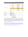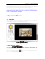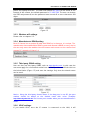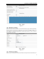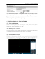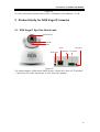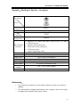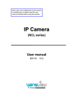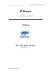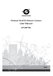
1
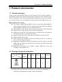
GO4 Vega I1 Eye One IP Camera User manual 2014-01 V1.1 Dear users, the configuration for this camera is professional, so please read the user manual carefully before using the camera. GO4 VEGA I1 IP CAMERA USER MANUAL Statement If the user manual cannot help you to solve the problem, please call our technical support center for solutions. We will update the content for the new functions without notice. Notice 1、 Installation Environment Keep away from high-temperature, heat source and direct sunlight; Keep away from water and should the unit get wet, switch off the power immediately. Avoid using in damp environment; the reference range for operation humidity is below 85%RH. Avoid using in extreme hot or cold environment, the reference range for operation temperature is -10C°~ +50C° Please install it horizontally or on wall mounts, avoid strenuous vibration place and do not put other equipments on top of the unit. 2、 Transport and Handling The package is specifically designed to ensure a safe delivery, so please do not use a different one. Do not move the ip camera from overheated to supercooled condition frequently, otherwise it will frost and shorten the service life. Do not move the item when is power on, otherwise the main board might be damaged. Notice: 1. Please check the power supply is working 2. Be careful not to hit the camera or subject it to strong impacts or shocks. 3. Do not directly touch the optical components for the image sensor, if necessary, please place a clean and moistened cloth with alcohol and wipe the dirt gently; When not in use, please place the dust cover on to the item to protect the image sensor. 4. Do not aim the camera directly into the sun or at other intense light sources that could affect the image quality (it is not the problem for the ip camera), also shorten the service life for the image sensor. 5. Keep away from laser when it is working, otherwise the image sensor can be damaged. 6. If the equipment is not working properly, please contact the store or the service center, do not disassemble or modify the equipment in any way. (Problems caused by unauthorized modification or repair should be at your own risk.) 2 GO4 VEGA I1 IP CAMERA USER MANUAL Index 1 PRODUCT INTRODUCTION ........................................................................................................ 4 1.1 PRODUCT SUMMARY ................................................................................................ 4 1.2 PACKAGE FOR TYPICAL PRODUCTION ........................................................................... 4 2 INSTALLATION GUIDE ................................................................................................................. 5 2.1 AP CONNECTION .................................................................................................... 5 2.2 WIRED CONNECTION TO LAN .................................................................................... 5 2.3 WIFI CONNECTING TO LAN ...................................................................................... 6 2.4 CONNECTING TO WAN ............................................................................................ 8 3 OPERATION OF IE BROWSER .................................................................................................. 9 3.1 VIEW VIDEO .......................................................................................................... 9 3.2 DEVICE INFORMATION ............................................................................................ 10 3.2.1 Device status ............................................................................................. 10 3.2.2 Device alias setting .................................................................................... 10 3.2.3 Device date and time setting .................................................................... 10 3.2.4 Local recording path .................................................................................. 11 3.3 DEVICE WEB SETTING ............................................................................................ 11 3.3.1 Basic network settings .............................................................................. 11 3.3.2 AP settings ................................................................................................ 11 3.3.3 Wireless wifi settings ................................................................................. 12 3.3.4 Manufacture’s DDNS setting...................................................................... 12 3.3.5 Third party DDNS setting .......................................................................... 12 3.3.6 UPnP settings ............................................................................................ 12 3.4 ALARM SETTINGS ................................................................................................. 13 3.4.1 Alarm service setting................................................................................. 13 3.4.2 Mail Service Setting ................................................................................... 14 3.4.3 FTP Service Setting ................................................................................... 14 3.4.4 Alarm log ................................................................................................... 15 3.5 USER AND DEVICE SETTING ..................................................................................... 16 3.5.1 Multi-device Setting ................................................................................... 16 3.5.2 User Settings ............................................................................................. 16 3.5.3 PTZ settings .............................................................................................. 16 3.5.4 Maintain ..................................................................................................... 17 4 VISITING DEVICE BY OTHER SOFTWARE ........................................................................... 17 4.1 OTHER WEB BROWSER ........................................................................................... 17 4.2 MOBILE PHONE SOFTWARE ...................................................................................... 17 4.3 CENTRALIZATION CONTROL .................................................................................... 17 5 PRODUCT FAMILY FOR GO4 VEGA IP CAMERAS ............................................................ 18 5.1 GO4 VEGA I1 EYE ONE QUICK LOOK ....................................................................... 18 APPENDIX: GO4 VEGA I1 EYE ONE – AT A GLANCE ............................................................ 19 3 GO4 VEGA I1 IP CAMERA USER MANUAL 1 Product introduction 1.1 Product summary Thank you for choosing GO4 Vega I1 series IP camera, the IP Camera combines a high quality digital video camera with network connectivity and a powerful web server to bring clear video to your desktop from anywhere on your local network or over the Internet. It is very suitable for family, shops, office building and so on. Main features for L series: ® The video is compressed by MJPEG. There are three VGA/QVGA/QQVGA video resolutions options. User can changes some parameters according to ® ® ® ® ® ® ® their demands to satisfy his own visual preferences; Infrared LED for night vision covers 5m area to give 24 hours monitoring; Support 802.11b/g/n protocol for wireless monitoring; Support AP mode, the PC and mobile phone can be directly connected to the camera by WiFI, no need for the router; Support motion detection, send alarm information by email and FTP; Support mobile phone view; Built in web server, all data is transferred through one port; it is easy for user to do the network setting; Manufacture attached a label at the bottom of each IP Camera, it include DDNS. When IP Camera is connected to the internet, this URL can be used ® to visit the device; Manufacturer provides free software, support Multi-view, long time recording, video playback etc; 1.2 Package for typical production Accessory Type Power adaptor 5V Stand CD Cable Bracket of Antenna plastic √ √ √ √ √ I1 camera Notice: ® Please check carefully if all listed items are included in the package, if anything is missing please contact vendor immediately. 4 GO4 VEGA I1 IP CAMERA USER MANUAL 2 Installation guide 2.1 AP connection Power on the camera (Please check carefully output voltage of power adapter, don’t insert incorrect adapter, otherwise it will damage the camera), after 2 minutes, the camera will work normally. You can use PC or mobile phone to connect directly the camera by WiFi, as Figure 1. Figure 1 1) Turn WLAN on in PC, and search available SSID, if searched AP SSID in device label, then you can connect it, default password is 123456789. 2) After connecting the camera, it will assign IP address to PC (PC wifi IP address need to be set to “obtain automatically”). 3) Open browser in PC, enter IP address of camera (AP default IP address is 192.168.246.1) then you can visit the camera (refer to 2.2). Note: Please check the user manual of mobile phone software when you connect to the camera by mobile phone. 2.2 Wired connection to LAN Power on the IP camera, connect IP camera to router by network cable, meanwhile, connect computer to the same router, example of figure 2. Figure 2 Insert CD to computer driver, double click “LSearch_en.exe” in the CD, run the software, click “Search”, select the device searched, click “Browse” to open 5 GO4 VEGA I1 IP CAMERA USER MANUAL browser, it will pop up user login dialog, enter default user name (admin) and password (123456) to login the camera as figure 3. Figure 3 We suggest using IE kernel browser to view the video (it can provide more functions, but user needs to install video player before viewing the video. Click “OCX Download ” to download OCX and install it. Notice: ® If you installed a firewall software in your PC, when you run the LSearch_en.exe, you might get a prompt saying “whether you want to block this program or not”, then you should choose not to block. ® You can hold on reset button on the camera for 10 seconds to restore factory default should you forget user name and password, during the process, don’t disconnect the power, otherwise the camera maybe damaged. 2.3 WIFI connecting to LAN You can connect the camera with router by wireless connection, as figure 4. Figure 4 Before connecting router by wifi, please connect them as chapter 2.2 to Login camera and enter wifi setting, and then operate as the following step, example of figure 5. 6 GO4 VEGA I1 IP CAMERA USER MANUAL Figure 5 Enter the Wireless LAN Setting, click the “Scan” button, it will show you all the wireless networks detected in the Wireless Network List column. Select one of them and tick “Using Wireless Lan”, then the relevant data of the selected wireless network will be shown in the following blanks. Input the password and click “Submit”, the WIFI setting is completed. Unplug the cable, then you can proceed to connect to router by wifi. Notice: When the device is connected both WIFI and wired, it will firstly connect to the wired network. If the camera enables DHCP to obtain IP address automatically, the IP address won’t be the same in wired connection and wifi connection: in this case we recommend to set a fixed IP address for the camera. 7 GO4 VEGA I1 IP CAMERA USER MANUAL 2.4 Connecting to WAN You should connect the LAN network to WAN first and do the port forwarding, connect as figure 6. Figure 6 If visit IP Camera from WAN, you must do port forwarding on the router. Example of figure 7. Figure 7 Operation Steps: 1) After login the interface of the router, choose “Port Forwarding” 2) Choose “Add custom Service” 3) Input IP camera http port 4) Input IP address of IP camera, click “Apply” 8 GO4 VEGA I1 IP CAMERA USER MANUAL After finishing the port forwarding, you can use WAN IP address of router and http port of camera to visit the camera by remote computer as figure 6. Notice: because the routers are different, the interface and settings will be too, so please refer to the user manual of your router or consult with router manufacturer in order to properly set port forwarding. 3 Operation of IE browser 3.1 View video After installing the plug-ins, click “Mode 1 to view” as Figure 3 to view the video (video as Figure 8, actual user interface might differ). Figure 8 1) Audio, Talk, Record, Snapshot You can click these buttons to perform audio, talk, record and snapshot functions. Note: about recording path, click button to enter setting interface, you can set it in “Local Recording Path”, as figure 9. 9 GO4 VEGA I1 IP CAMERA USER MANUAL Figure 9 2) Multipicture change button If you add multi-devices in chapter 3.4.2 “multi-device setting”, it will connect other device to display pictures automatically when changing to 4, 9 split screen. In playing video area, you can select a picture to control audio, talk, record, snapshot and PTZ control etc. 3) Viewing control area You can control PTZ moving, picture reversal and mirror etc. when viewing video, and can adjust picture parameters, including resolution, brightness etc. The camera supports 16 preset points, you can set one place as preset point when moving the PTZ to a place, also can call the preset point when the camera move to another place, so the camera can return to set place. button can control work mode of IR LED. IR LED has two modes, auto Note: and forced close. In auto mode the IR LED will power on or off according to environment light; in forced close mode the IR LED will be always off. 4) Setting device parameters Click button to enter setting interface, you can set all parameters of the camera described in chapter 3.2 to 3.5. Only administrator can login to set these parameters. 3.2 Device information 3.2.1 Device status The user can check “Device firmware version”,” Web UI version”, “Alias”, “AP MAC” etc. 3.2.2 Device alias setting The user can rename the camera for ease of use, i.e “Home”, “Office2” etc. 3.2.3 Device date and time setting You can enable “Sync with NTP Server” when the device is connected to WAN, but you need to select correct time zone where the camera is located, otherwise you have to select“ Sync with PC time”. 10 GO4 VEGA I1 IP CAMERA USER MANUAL Figure 10 Remark:Please carefully check the camera time, so it can be sure the alarm accuracy. 3.2.4 Local recording path The camera will automatically create a file folder named “Record files” when the user doesn’t set “local recording path” and launch recording directly, and then save recording file to the folder, as figure 11. Figure 11 3.3 Device web setting 3.3.1 Basic network settings The user can also enter the Basic Network Settings to set the IP address except using the search software “LSearch_en.exe”. See below Figure 12. Figure 12 Remark: The router connected to camera need to enable DHCP when the user uses “obtain IP from DHCP server”; the routers enable DHCP by default. 3.3.2 AP settings Example of chapter 2.1, the user can directly connect to the camera by mobile 11 GO4 VEGA I1 IP CAMERA USER MANUAL phone and laptop with WiFi. The label with default AP SSID can be found at the bottom of the camera, the default password is 123456789. The user can change the SSID and password, but the password must contain 8 or more characters and digits. Figure 13 3.3.3 Wireless wifi settings Please refer to chapter 2.2. 3.3.4 Manufacture’s DDNS setting Each IP Camera has an unique ID label with DDNS on its bottom, it is unique. The manufacturer has established a DDNS system and allotted a DDNS to every device, the user only enters the website into the browser and connect to the camera from remote PC, example of figure 14. Figure 14 3.3.5 Third party DDNS setting User can also use third party DDNS, such as www.dyndns.com. In this case the user must apply for a free domain name from the DNS provider and fill the info into the below blanks (Figure 15) and save the settings. Only then the domain name can be used. Figure 15 Notice:Using the third party domain name, if the http port is not 80, the port number should be added to the domain name with colon. Example: http://btest.dyndns.biz:81. Don’t enter port number when you use manufacturer’s DDNS. 3.3.6 UPnP settings If you enable UPnP, once the IP camera is connected to the LAN, it will 12 GO4 VEGA I1 IP CAMERA USER MANUAL communicate with the router in the LAN and do the port forwarding with open port of router automatically. In figure 16, you only tick “Using UPnP to Port Mapping” to finish the setting. Figure 16 Before using the UPnP function, please make sure the router’s UPnP function has been enabled. Not all the routers support UPnP perfectly. Please test if the router works well with the equipment, if not, we suggest you to disable this function and set the port forwarding manually. 3.4 Alarm Settings 3.4.1 Alarm service setting If the user needs to monitor a fixed area to check if there is any motion, it will detect the motion and trigger the alarm. In the motion detect sensibility, the smaller the value, the more is the sensitivity. After triggering the alarm, you can adopt several alarm modes in armed time, example of figure 17. Link to the Preset when alarming: need to set preset point of the camera; Send alarm info by email (an email include a picture); every alarm trigger a email; Send the snap to the FTP server, user can also set the interval time between two pictures. The device only triggers alarm when it detects any motion in armed time. User can set schedule time to be “all the time”, also assign the armed time. Before you set “Time Schedule”, please go to Date and Time settings to set the correct time for the item. 13 GO4 VEGA I1 IP CAMERA USER MANUAL Figure 17 3.4.2 Mail Service Setting When the device detects motion, it can send an email to your selected email box, but you need to set email service parameters correctly first. Example of figure 18, click “Submit” to save these parameters, and then you can click “Test” to check if the setting is successful. Figure 18 3.4.3 FTP Service Setting When motion is detected, the device will take a local picture and send them to a 14 GO4 VEGA I1 IP CAMERA USER MANUAL designated FTP server, but the user needs to set the FTP setting correctly. As figure 19, after the setting is finished, click “Test” to check your settings are correct or not. Figure 19 Notice:To use the FTP function, you need to apply a user with permission to write and create submenu and some memory space. 3.4.4 Alarm log You can inquire when the device performs alarm in alarm log. Figure 20 15 GO4 VEGA I1 IP CAMERA USER MANUAL 3.5 User and device setting 3.5.1 Multi-device Setting As Figure 21, User can add a maximum of 9 devices to view video simultaneously. Click “refresh” button to check the device in the LAN. When click a device, will popup setting dialogue and enter the device info, and click “Add” to add device. After that, must click “Setup” button to save device. Figure 21 3.5.2 User Settings Figure 22 3.5.3 PTZ settings Figure 23 Note: When you set cruise turns all the time, the camera will automatically stop 16 GO4 VEGA I1 IP CAMERA USER MANUAL after cruising one hour. 3.5.4 Maintain Figure 24 Click “Restore factory settings”, a pop up dialog will ask you if you’d like to restore to factory settings, then the camera will restore factory settings and reboot after your confirmation. There are two types software in the camera, one is device firmware, another is Web UI, and you can upgrade them respectively. 4 Visiting device by other software 4.1 Other web browser Besides IE browser, you can visit the camera by Firefox, Safari, Chrome, Opera browser etc., please select “Mode 2 to view”. 4.2 Mobile phone software For more information, please see the user manual for mobile phone in attached CD, or download the latest software and user manual in our website. 4.3 Centralization Control IPCMonitor is a free software offered by factory, several devices on LAN and WAN can be browsed at the same time. The software also supports snapshot, video record, scheduled record, alarming and so on. The interface is as figure 25. 17 GO4 VEGA I1 IP CAMERA USER MANUAL Figure 25 For more information, please refer to the <<IPCMonitor User Manual>> in CD. 5 Product family for GO4 Vega IP cameras 5.1 GO4 Vega I1 Eye One Quick Look Photoresistor IR LED MIC RJ45 Audio OUT DC Power Antenna I/O Alarm Figure 26 The camera adopts 300K pixels CMOS sensor, 3.6mm lens, built in PTZ and MIC, 11 pieces IR LED, audio out socket. It uses 5V power adaptor. 18 GO4 VEGA I1 IP CAMERA USER MANUAL Appendix:GO4 Vega I1 Eye One – At a glance Product Function Video MJPEG compression Resolution VGA/QVGA/QQVGA Max. 30FPS Framerate Audio ADPCM compression Support HTTP, DHCP, IEEE 802.11b/g/n, NTP, FTP, SMTP, P2Pprotocol etc; Main software Support motion detection; function three level of user authority; PTZ preset point ; support upgrading online Lens 3.6mm Pan/Tilt Tilt 100°Pan 350° Night vision 11pcs IR LED, 8m distance Wi-Fi Yes Audio Built in MIC, audio out Power supply 5V, power consumption<6W Work condition Body size -10℃~ 50℃ under 85%RH 135*103*127mm Statement: 1. If you have any questions of the manual, please contact our technical support. 2. This manual will be updated periodically; the company reserves the right to update this manual without prior notice. 19