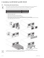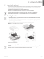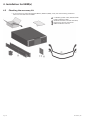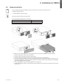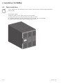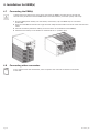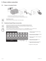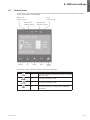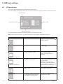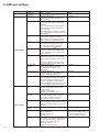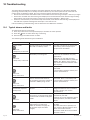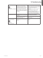
1
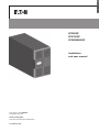
ENGLISH
9PX8KSP
9PX10KSP
9PXEBM360SP
Installation
and user manual
Copyright © 2014 EATON
All rights reserved.
Service and support:
Call your local service representative
614-00205-01_EN
SAFETY INSTRUCTIONS
SAVE THESE INSTRUCTIONS. This manual contains important instructions
that should be followed during installation and maintenance of the UPS and batteries.
The 9PX models that are covered in this manual are intended for installation
in an environment within 32 to 104°F / 0 to 40°C, free of conductive contaminant.
This equipment has been tested and found to comply with the limits for a Class A digital device,
pursuant to Part 15 of the FCC Rules. These limits are designed to provide reasonable protection against
harmful interference when the equipment is operated in a commercial environment. This equipment
generates, uses, and can radiate radio frequency energy and, if not installed and used in accordance
with the instruction manual, may cause harmful interference to radio communications. Operation of
this equipment in a residential area is likely to cause harmful interference in which case the user will
be required to correct the interference at his own expense.
Certification standards
• Safety: UL 1778 4th
CAN/CSA C22.2 No 107.3-05, Ed.2.
• EMC: IEC/EN 62040-1 / Ed.1: 2008
IEC/EN 62040-2 / Ed.2: 2006.
FCC part 15 Class A.
• Performance: IEC/EN 62040-3 / Ed.2.0: 2011.
• IEC 61000-4-2 (ESD): level 3.
• IEC 61000-4-3 (Radiated field): level 3.
• IEC 61000-4-4 (EFT): level 4.
• IEC 61000-4-5 (Fast transients): level 4.
• IEC 61000-4-6 (Electromagnetic field): level 3.
• IEC 61000-4-8 (Conducted magnetic field): level 4.
Special symbols
The following are examples of symbols used on the UPS or accessories to alert you to important
information:
RISK OF ELECTRIC SHOCK - Observe the warning associated with the risk of electric shock symbol.
Important instructions that must always be followed.
Do not discard the UPS or the UPS batteries in the trash.
This product contains sealed lead acid batteries and must be disposed as it's explain in this manual.
For more information, contact your local recycling/reuse or hazardous waste center.
This symbol indicates that you should not discard waste electrical or electronic equipment (WEEE)
in the trash. For proper disposal, contact your local recycling/reuse or hazardous waste center.
Information, advice, help.
Refer to the user manual of UPS accessories.
Page 2
614-00205-01_EN
Safety of persons
• RISK OF VOLTAGE BACKFEED. The system has its own power source (the battery). Isolate the UPS
and check for hazardous voltage upstream and downstream during lockout-tagout operation.
Terminal blocks may be energized even if the system is disconnected from the AC power source.
• Dangerous voltage levels are present within the system. It should be opened exclusively by
qualified service personnel.
• The system has its own power source (the battery). Consequently, the power outlets may be
energized even if the systems is disconnected from the AC power source. Dangerous voltage levels
are present within the system. It should be opened exclusively by qualified service personnel.
• The system must be properly grounded.
• The battery supplied with the system contains small amounts of toxic materials.
To avoid accidents, the directives listed below must be observed:
- Servicing of batteries should be performed or supervised by personnel knowledgeable about
batteries and the required precautions.
- When replacing batteries, replace with the same type and number of batteries or battery packs.
- Do not dispose of batteries in a fire. The batteries may explode.
- Batteries constitute a danger (electrical shock, burns). The short-circuit current may be very high.
• Precautions must be taken for all handling:
- Wear rubber gloves and boots.
- Do not lay tools or metal parts on top of batteries.
- Disconnect charging source prior to connecting or disconnecting battery terminals.
- Determine if battery is inadvertently grounded. If inadvertently grounded, remove source from
ground. Contact with any part of a grounded battery can result in electrical shock. The likelihood
of such shock can be reduced if such grounds are removed during installation and maintenance
(applicable to equipment and remote battery supplies not having a grounded supply circuit).
Product safety
• The UPS connection instructions and operation described in the manual must be followed in
the indicated order.
• CAUTION - To reduce the risk of fire, the unit connects only to a circuit provided with branch circuit
overcurrent protection with:
- 60A rating, for 8kVA models,
- 60A rating, for 10kVA models,
in accordance with the National Electric Code, ANSI/NFPA 70.
The upstream circuit breaker must be easily accessible. The unit can be disconnected from AC
power source by opening this circuit breaker.
• A means of disconnection and overcurrent protection devices shall be provided by others for
permanently connected AC input/output circuits.
• Check that the indications on the rating plate correspond to your AC powered system and
to the actual electrical consumption of all the equipment to be connected to the system.
• For PLUGGABLE EQUIPMENT, the socket-outlet shall be installed near the equipment and shall
be easily accessible
• Never install the system near liquids or in an excessively damp environment.
• Never let a foreign body penetrate inside the system.
• Never block the ventilation grates of the system.
• Never expose the system to direct sunlight or source of heat.
• If the system must be stored prior to installation, storage must be in a dry place.
• The admissible storage temperature range is 32 to 104°F / 0 to 40ºC.
• The system is not for use in a computer room AS DEFINED IN the standard for the Protection
of Information Technology Equipment, ANSI/NFPA 75.
Contact Eaton resellers to order a special battery kit, if needed to meet the ANSI/NFPA 75
requirement.
For Model 9PX8KSP, Disconnection Device - CAUTION - A disconnect switch shall be provided by
others for AC output circuit. To reduce the risk of fire, connect only to a circuit provided with branch
circuit overcurrent protection for 40 amperes rating in accordance with the National Electric Code.
ANSI/NFPA 70.
For Model 9PX10KSP, Disconnection Device - CAUTION - A disconnect switch shall be provided by
others for AC output circuit. To reduce the risk of fire, connect only to a circuit provided with branch
circuit overcurrent protection for 45 amperes rating in accordance with the National Electric Code.
ANSI/NFPA 70.
614-00205-01_EN
Page 3
ENGLISH
SAFETY INSTRUCTIONS
SAFETY INSTRUCTIONS
Special precautions
• The unit is heavy: wear safety shoes and use vacuum lifter preferentially for handling operations.
• All handling operations will require at least two people (unpacking, lifting, installation in rack
system).
• For EBM, straps are provided only for unpacking manually the unit from the carton; don’t use the
straps to carry the unit around. The unit can slip from the straps during handling (risk of injury and
product damage):
- keep 12in / 30cm minimum distance between the straps
- lift the unit carefully and keep it at low height
- keep the unit horizontal during unpacking.
• Before and after the installation, if the UPS remains de-energized for a long period, the UPS must be
energized for a period of 24 hours, at least once every 6 months (for a normal storage temperature
less than 77°F (25°C)). This charges the battery, thus avoiding possible irreversible damage.
• During the replacement of the Battery Module, it is imperative to use the same type and number of
element as the original Battery Module provided with the UPS to maintain an identical level of
performance and safety. In case of doubt, don’t hesitate to contact your EATON representative.
• All repairs and service should be performed by AUTHORIZED SERVICE PERSONNEL ONLY.
There are NO USER SERVICEABLE PARTS inside the UPS.
Page 4
614-00205-01_EN
1. Introduction........................................................................................ 6
1.1
Environmental protection................................................................................................6
2. Presentation....................................................................................... 8
2.1
2.2
2.3
Weights and dimensions................................................................................................8
Rear panel layout............................................................................................................9
Accessories (optional).....................................................................................................9
3. Installation for 9PX 8K SP and 9PX 10K SP................................... 10
3.1
3.2
3.3 3.4
3.5
3.6
Inspecting the equipment ............................................................................................ 10
Unpacking the cabinet.................................................................................................. 10
Checking the accessory kit (9PX 8K SP/9PX 10K SP)................................................... 11
Tower installation.......................................................................................................... 12
Rack installation ........................................................................................................... 13
Connecting the internal battery.................................................................................... 14
4. Installation for EBM(s).................................................................... 15
4.1
4.2
4.3 4.4
4.5
4.6
4.7
4.8
Inspecting the equipment ............................................................................................ 15
Unpacking the cabinet.................................................................................................. 15
Checking the accessory kit........................................................................................... 16
Prepare installation....................................................................................................... 17
Tower installation.......................................................................................................... 18
Rack installation ........................................................................................................... 19
Connecting the EBM(s) ................................................................................................20
Connecting other accessories .....................................................................................20
5. Power cables connection................................................................ 21
5.1 Installation requirements..............................................................................................21
5.2 Access to terminal blocks.............................................................................................22
5.3 Hardwired Input/Output connection.............................................................................22
6. HMI and settings............................................................................. 23
6.1
6.2
6.3
6.4
Control panel.................................................................................................................23
LCD description............................................................................................................24
Display functions..........................................................................................................25
User settings................................................................................................................25
7. Operation.......................................................................................... 27
7.1 7.2 7.3 7.4 7.5
7.6 7.7 UPS startup and shutdown...........................................................................................27
Operating modes..........................................................................................................28
Transferring the UPS between modes..........................................................................29
Configuring Bypass settings.........................................................................................29
Configuring battery settings.........................................................................................29
Retrieving the Event log................................................................................................30
Retrieving the Fault log.................................................................................................30
8. Communication............................................................................... 31
8.1 Communication ports...................................................................................................31
8.2 Eaton Intelligent Power Software suite........................................................................34
9. UPS maintenance............................................................................ 35
9.1
9.2
9.3
9.4
9.5
9.6
Equipment care.............................................................................................................35
Storing the equipment..................................................................................................35
When to replace batteries............................................................................................35
Replacing batteries.......................................................................................................36
Replacing the UPS equipped with a Maintenance Bypass (BPE20MBB1A).................39
Recycling the used equipment.....................................................................................39
10. Troubleshooting.............................................................................. 40
10.1 Typical alarms and faults...............................................................................................40
10.2 Silencing the alarm.......................................................................................................42
10.3 Service and support......................................................................................................42
11. Specifications................................................................................. 43
11.1 Model specifications.....................................................................................................43
12. Glossary.......................................................................................... 47
614-00205-01_EN
Page 5
ENGLISH
Contents
1. Introduction
Thank you for selecting an EATON product to protect your electrical equipment.
The 9PX range has been designed with the utmost care.
We recommend that you take the time to read this manual to take full advantage of the many features
of your UPS (Uninterruptible Power System).
Before installing your 9PX, please read the booklet presenting the safety instructions.
Then follow the indications in this manual.
To discover the entire range of EATON products and the options available for the 9PX range,
we invite you to visit our web site at powerquality.eaton.com or contact your EATON representative.
1.1
Environmental protection
EATON has implemented an environmental-protection policy.
Products are developed according to an eco-design approach.
Substances
This product does not contain CFCs, HCFCs or asbestos.
Packing
To improve waste treatment and facilitate recycling, separate the various packing components.
• The cardboard we use comprises over 50% of recycled cardboard.
• Sacks and bags are made of polyethylene.
• Packing materials are recyclable and bear the appropriate identification symbol
Materials
Abbreviations
Number in
the symbols
Polyethylene terephthalat
PET
01
High-density polyethylene
HDPE
02
Polyvinyl chloride
PVC
03
Low-density polyethylene
LDPE
04
Polypropylene
PP
05
Polystyrene
PS
06
Follow all local regulations for the disposal of packing materials.
End of life
EATON will process products at the end of their service life in compliance with local regulations.
EATON works with companies in charge of collecting and eliminating our products at the end of
their service life.
Product
The product is made up of recyclable materials.
Dismantling and destruction must take place in compliance with all local regulations concerning waste.
At the end of its service life, the product must be transported to a processing center for electrical and
electronic waste.
Battery
The product contains lead-acid batteries that must be processed according to applicable local regulations
concerning batteries.
The battery may be removed to comply with regulations and in view of correct disposal.
Page 6
614-00205-01_EN
The Eaton® 9PX uninterruptible power system (UPS) protects your sensitive electronic equipment from
the most common power problems, including power failures, power sags, power surges, brownouts, line
noise, high voltage spikes, frequency variations, switching transients, and harmonic distortion.
Power outages can occur when you least expect it and power quality can be erratic. These power problems
have the potential to corrupt critical data, destroy unsaved work sessions, and damage hardware - causing
hours of lost productivity and expensive repairs.
With the Eaton 9PX, you can safely eliminate the effects of power disturbances and guard the integrity
of your equipment. Providing outstanding performance and reliability, the Eaton 9PX’s unique benefits
include:
•
True online double-conversion technology with high power density, utility frequency independence,
and generator compatibility.
614-00205-01_EN
•
BM® technology that uses advanced battery management to increase battery service life,
A
optimize recharge time, and provide a warning before the end of useful battery life.
•
Selectable High Efficiency mode of operation.
•
tandard communication options: Network-MS card (Web/SNMP), one RS-232 communication
S
port, one USB communication port, and relay output contacts.
•
Optional connectivity cards with enhanced communication capabilities (Modbus-MS, Relay-MS).
•
Extended runtime with up to four Extended Battery Modules (EBMs) per UPS.
•
Firmware that is easily upgradable without a service call.
•
Remote On/Off control through Remote On/Off (ROO) and Remote Power Off (RPO) ports.
•
Backed by worldwide agency approvals.
Page 7
ENGLISH
1. Introduction
2. Presentation
2.1
Weights and dimensions
9PX 8K SP / 9PX 10K SP
Tower installation
Description
9PX8KSP
9PX10KSP
Rack installation
Weights
(lb/kg)
225 / 102
225 / 102
Dimensions H x W x D
(inch/mm)
10.3 x 17.4 x 29.4 / 262 x 440 x 745
10.3 x 17.4 x 29.4 / 262 x 440 x 745
9PX EBM 360SP
Tower installation
Description
9PXEBM360SP
Page 8
Rack installation
Weights
(lb/kg)
163.2 / 74
Dimensions H x W x D
(inch/mm)
5.2 x 17.4 x 25.4 / 130 x 440 x 645
614-00205-01_EN
2.2
Rear panel layout
9PX 8K SP / 9PX 10K SP
RS232 communication port
USB communication port
3 Dry (relay) contacts communication
port
4 Connector for MBP and ROO (Remote
On/Off) control
5 Connectors for automatic recognition
of battery module
6 Connector for RPO (Remote Power Off)
control
7 Slot for optional communication card
8 Connector for battery module
9 Input/Output terminal blocks
10 (1) L6-30R outlet
11 (2) L14-30R outlets
1
2
9PX EBM 360SP
(Extended Battery Module of the 9PX 8K SP and 9PX 10K SP)
12 Connectors
for battery modules
(to the UPS or to the other battery
modules)
13 Connectors for automatic recognition
of battery modules
2.3
Accessories (optional)
614-00205-01_EN
Part number
Description
9PXEBM360SP
Extended Battery Module
Modbus-MS
Modbus and network card
Relay-MS
Relay card
BPE20MBB1A
External maintenance Bypass for 9PX8KSP and 9PX10KSP
BINTSYS
Battery Integration System
EBMCBL360
6 feet cable for 9PXEBM360SP
Page 9
ENGLISH
2. Presentation
3. Installation for 9PX 8K SP and 9PX 10K SP
3.1
Inspecting the equipment
If any equipment has been damaged during shipment, keep the shipping cartons and packing materials
for the carrier or place of purchase and file a claim for shipping damage. If you discover damage after
acceptance, file a claim for concealed damage.
To file a claim for shipping damage or concealed damage:
1. File with the carrier within 15 days of receipt of the equipment;
2. Send a copy of the damage claim within 15 days to your service representative.
Check the battery recharge date on the shipping carton label. If the date has passed and the
batteries were never recharged, do not use the UPS. Contact your service representative.
3.2
Unpacking the cabinet
• U
npacking the cabinet in a low-temperature environment may cause condensation to occur in and
on the cabinet. Do not install the cabinet until the inside and outside of the cabinet are absolutely
dry (hazard of electric shock).
• T
he cabinet is heavy (see "Weights and dimensions" on page 43). Follow Special precautions
provided on page 4 and on the carton.
Unpack the equipment and remove all the packing materials and shipping carton.
Note: Do not lift the UPS from the front panel.
Unpacking UPS.
Discard or recycle the packaging in a responsible manner, or store it for future use.
Place the cabinet in a protected area that has adequate airflow and is free of humidity, flammable gas, and
corrosion.
Packing materials must be disposed of in compliance with all local regulations concerning waste.
Recycling symbols are printed on the packing materials to facilitate sorting.
Page 10
614-00205-01_EN
3.3 Checking the accessory kit (9PX 8K SP/9PX 10K SP)
•
Verify that the following additional items are included with the UPS:
User manual
Safety instructions
3 Warranty sheet
4 Software CD-ROM
5 RS232 communication cable
6 USB communication cable
7 Network-MS communication card
8 Rack kit for 19-inch enclosures
9 Screwdriver
10 2 x internal battery pack
1
2
614-00205-01_EN
Page 11
ENGLISH
3. Installation for 9PX 8K SP and 9PX 10K SP
3. Installation for 9PX 8K SP and 9PX 10K SP
3.4
Tower installation
If you ordered other UPS accessories, refer to specific user manuals to check the tower installation
with the UPS.
To install the cabinet:
1. Place the UPS on a flat, stable surface in its final location.
2. Always keep 150 mm of free space behind the UPS rear panel.
3. If installing additional cabinets, place them next to the UPS in their final location.
4. Install mounting brackets to attach the EBM to UPS module (if EBM is present).
• Adjustment of the orientation of the LCD
panel and of the logo.
• Adjustment of the angle of vision of the LCD
panel.
Page 12
614-00205-01_EN
3.5
Rack installation
• Rack mounting of UPS and accessory modules.
Follow steps 1 to 4 for module mounting on the rails.
The rails and necessary hardware are supplied by EATON.
If you ordered other UPS accessories, refer to specific user manuals to check the rack installation
with the UPS.
614-00205-01_EN
Page 13
ENGLISH
3. Installation for 9PX 8K SP and 9PX 10K SP
3. Installation for 9PX 8K SP and 9PX 10K SP
3.6
Connecting the internal battery
Do not make unauthorized changes to the UPS; otherwise, damage may occur to your equipment
and void your warranty. Do not connect the UPS to utility until installation is completed.
This step requires two service personnel, the UPS and internal battery are heavy.
Description
9PX 8K SP/9PX 10K SP without internal battery
9PX 8K SP/9PX 10K SP internal battery
•
•
•
•
•
Weights (lb/kg)
91 / 41
67.3 / 30.5
Mount the UPS on rack.
Remove the center cover of the front panel.
Remove the four screws to open the front panel.
Remove the three screws to pull out the metal protection cover of the battery.
Put the battery pack, screw back the metal protection cover, connect the battery and put back the
front panel, then clip the center cover.
Battery connectors may be coupled
to either battery pack.
A small amount of arcing may occur when connecting the internal batteries. This is normal and will
not harm personnel. Connect the cables quickly and firmly.
Page 14
614-00205-01_EN
4.1
Inspecting the equipment
If any equipment has been damaged during shipment, keep the shipping cartons and packing materials
for the carrier or place of purchase and file a claim for shipping damage. If you discover damage after
acceptance, file a claim for concealed damage.
To file a claim for shipping damage or concealed damage:
1. File with the carrier within 15 days of receipt of the equipment;
2. Send a copy of the damage claim within 15 days to your service representative.
Check the battery recharge date on the shipping carton label. If the date has passed and the
batteries were never recharged, do not use the EBM. Contact your service representative.
4.2
Unpacking the cabinet
• U
npacking the cabinet in a low-temperature environment may cause condensation to occur in and
on the cabinet. Do not install the cabinet until the inside and outside of the cabinet are absolutely
dry (hazard of electric shock).
• T
he cabinet is heavy (see "Weights and dimensions" on page 43). Follow Special precautions
provided on page 4 and on the carton.
Unpack the equipment and remove all the packing materials and shipping carton.
Note: Do not lift the EBM from the front panel.
Unpacking Extended Battery Module.
Discard or recycle the packaging in a responsible manner, or store it for future use.
Place the cabinet in a protected area that has adequate airflow and is free of humidity, flammable gas, and
corrosion.
Packing materials must be disposed of in compliance with all local regulations concerning waste.
Recycling symbols are printed on the packing materials to facilitate sorting.
614-00205-01_EN
Page 15
ENGLISH
4. Installation for EBM(s)
4. Installation for EBM(s)
4.3 Checking the accessory kit
• If you ordered an optional Extended Battery Module (EBM), verify that the following additional
items are included with the EBM:
1
2
3
4
Page 16
2 x Battery power cable, attached with
battery detection cable
Stabilizer bracket (4 screws included)
Rack kit for 19-inch enclosures
EBM Installation manual.
614-00205-01_EN
4.4
Prepare installation
If you ordered other UPS accessories, refer to specific user manuals to check the rack
installation with the UPS.
• Prepare EBM for rack mounting.
This step requires two service personnel.
The Extended Battery Module is very heavy.
Description
9PX EBM 360SP without internal battery
9PX EBM 360SP internal battery
Weights (lb/kg)
28.7 / 13
67.3 / 30.5
To
•
•
•
•
ease its rack mounting, you can remove the battery pack from the EBM as explained below.
Remove the center cover of the front panel.
Remove the four screws to open the front panel.
Remove the three screws to pull out the metal protection cover of the battery.
Pull out the plastic handle of the left and right battery packs, and slide the packs out slowly on to a
flat and stable surface. Use two hands to support the battery packs. Set them aside for reinstalling
after that the EBM is rack mounted.
• Mount the EBM on rack (see "Rack installation" on page 13 ).
• Put back the battery packs, screw back the metal protection cover and the front panel, then clip the
center cover.
614-00205-01_EN
Page 17
ENGLISH
4. Installation for EBM(s)
4. Installation for EBM(s)
4.5
Tower installation
If you ordered other UPS accessories, refer to specific user manuals to check the tower installation
with the UPS.
To install the cabinet:
1. Place the UPS on a flat, stable surface in its final location.
2. Always keep 150 mm of free space behind the UPS rear panel.
3. If installing additional cabinets, place them next to the UPS in their final location.
4. Install mounting brackets to attach the EBM to UPS module.
Page 18
614-00205-01_EN
4.6
Rack installation
• Rack mounting of UPS and accessory modules.
Follow steps 1 to 4 for module mounting on the rails.
The rails and necessary hardware are supplied by EATON.
If you ordered other UPS accessories, refer to specific user manuals to check the rack installation
with the UPS.
614-00205-01_EN
Page 19
ENGLISH
4. Installation for EBM(s)
4. Installation for EBM(s)
4.7
Connecting the EBM(s)
A small amount of arcing may occur when connecting an EBM to the UPS. This is normal and
will not harm personnel. Insert the EBM cable into the UPS battery connector quickly and firmly.
1. Plug the EBM power cable(s) into the battery connector(s). Up to 4 EBMs may be connected
to the UPS.
2. Verify that the EBM connections are tight and that adequate bend radius and strain relief exist for each
cable.
3. Connect the battery detection cable(s) to the connector of the UPS and of the EBM(s).
4. Check that the battery circuit breaker is switched to the “I” position (On).
4.8
Connecting other accessories
If you ordered other UPS accessories, refer to specific user manuals to check the connection
to the UPS.
Page 20
614-00205-01_EN
5.1 Installation requirements
Recommended protective devices and cable cross-sections
Backfeed protection
utility
Circuit breaker
Note: Do not feed neutral through circuit breaker or backfeed.
1. Recommended upstream protection
UPS power rating
Upstream circuit breaker
9PX 8K SP
8000VA
D Curve - 60A
9PX 10K SP
10000VA
D Curve - 60A
2. Recommended backfeed protection
One of following AC contactors used as backfeed protection devices shall be installed external
to Main Input of UPS. The following Eaton XCE050D contactors are recommended.
Note that the appropriate contactor should be sourced based upon the on-site voltage.
EATON XTCE050D series contactor
Nominal Coil
Voltage
Part number
XTCE050D00D
XTCE050D00G
XTCE050D00B
208
220
240
Freq
60
60
60
Pickup
Min
0.8
0.8
0.8
Max
1.1
1.1
1.1
Drop out
Min
Max
0.3
0.6
0.3
0.6
0.3
0.6
Pickup
Min
166
176
192
Manufacture
Type
Rating
Moeller GMBH
DILM-50
General Use - 80A, 600VAC, 50/60Hz
Max
229
242
264
Drop out
Min
Max
62
125
66
132
72
144
3. Recommended wire size
Terminal
position
Wire
function
Terminal wire
size rating
Minimum input
wire size
Tightening
torque
L1
Phase
8-4 AWG (10-25 mm2)
18 lb in / 2.03 Nm
L2
Phase
6 AWG (75°C)
For 9PX 8K SP
N
Neutral
Ground
4 AWG (75°C)
For 9PX 10K SP
Copper wire, solid or stranded.
614-00205-01_EN
Page 21
ENGLISH
5. Power cables connection
5. Power cables connection
5.2 Access to terminal blocks
• Remove the terminal blocks cover (two screws).
• Punch the knockouts and insert the cables/conduits inside.
High leakage current:
Earth connection essential before connecting supply.
5.3 Hardwired Input/Output connection
This type of connection must be carried out by qualified electrical personnel
Before carrying out any connection, check that the upstream protection devices
(Input AC source) is open "O" (Off).
Always connect the ground wire first.
If you ordered an external maintenance Bypass such as, BPE20MBB1A, refer to specific user
manual to check the terminal blocks connection of the UPS with this accessory.
1. Insert the Input AC cable through
the cable gland.
2. C
onnect the four cables to the Input
AC source terminal blocks.
3. Insert the Output cable through the
cable gland.
4. C
onnect the four cables to the
Output terminal blocks.
5. P
ut back and secure the terminal
blocks cover with the screw.
6. Tighten the cable glands.
Page 22
614-00205-01_EN
6.1
Control panel
The UPS has a five-button graphical LCD. It provides useful information about the UPS itself, load status,
events, measurements and settings.
Online mode
indicator (green)
Fault
indicator (red)
Battery mode
indicator (orange)
Escape
Up
Down
Bypass mode
indicator (orange)
Enter
On/Off
button
The following table shows the indicator status and description:
Indicator
Green
Orange
Orange
Red
614-00205-01_EN
Status
Description
On
The UPS is operating normally on Online or on High
Efficiency mode.
On
The UPS is on Battery mode.
On
The UPS is on Bypass mode.
On
The UPS has an active alarm or fault.
See "Troubleshooting" on page 40 for additional
information.
Page 23
ENGLISH
6. HMI and settings
6. HMI and settings
6.2
LCD description
After 5 minutes of inactivity, the LCD displays the screen saver.
The LCD backlight automatically dims after 10 minutes of inactivity. Press any button to restore the screen.
Operation status
Load/equipment status
Battery status
Efficiency information
The following table describes the status information provided by the UPS.
Note: If other indicator appears, see "Troubleshooting" on page 40 for additional information.
Operation status
Standby mode
Cause
The UPS is Off.
Online mode
The UPS is operating normally.
The UPS is powering and protecting
the equipment.
Battery mode
A utility failure has occured and
the UPS is on Battery mode.
The UPS is powering the equipment
with the battery power.
Prepare your equipment for
shutdown.
The UPS is on Battery mode and
the battery is running low.
This warning is approximate, and
the actual time to shutdown may
vary significantly.
Depending on the UPS load
and number of Extended Battery
Modules (EBMs), the "Battery Low"
warning may occur before the
battery reaches 20% capacity.
The UPS is powering and
protecting the equipment.
1 beep every 10 seconds
End of backup time
1 beep every 3 seconds
Page 24
Description
Equipment is not powered until
button is pressed.
High Efficiency mode
The UPS is operating on High
Efficiency mode.
Bypass mode
An overload or a fault has occurred, Equipment is powered but not
or a command has been received,
protected by the UPS.
and the UPS is in Bypass mode.
614-00205-01_EN
6.3
Display functions
Press the Enter (
) button to activate the menu options. Use the two middle buttons (
through the menu structure. Press the Enter (
) button to select an option. Press the
or return to the previous menu.
Main menu
Measurements
Submenu
Control
Go to Bypass /
Go back normal
Start battery test
Reset fault state
Restore factory set
Reset average power
Reset cumul. power
Dry contacts test
Local settings
In/Out settings
On/Off settings
Battery settings
Event filter
Event list
Reset event list
Fault list
Reset fault list
Settings
Event log
Fault log
Identification
Register product
6.4
and ) to scroll
button to cancel
Display information or Menu function
[Total Load] W VA A PF / [Load phase 1 (N-L1)] W VA A PF /
[Load phase 2 (N-L2)] W VA A PF] / [Input/Bypass] V- L1 V- L2 Hz
/ [Total Output (L1-L2)] V Hz (N-L1)V (N-L2)V / [Efficiency] % /
[Battery] % min V1 V2 / [DC bus] V / [Average power usage] Wh /
[Cumulat. power usage] kWh since date
Transfers the UPS on Bypass mode /
Transfers the UPS on Line mode
Starts a manual battery test
Clears active fault
Returns all settings to original values
Clears average power usage measurement
Clears cumulated power usage measurement
Tests dry contact relay outputs
Sets product general parameters
Sets Output parameters
Sets On/Off conditions
Sets battery configuration
Selects faults, alarms and/or events to display
Displays the events stored
Clears events
Displays the faults stored
Clears faults
[Product type/model] / [Part/Serial number] / [UPS/NMC
firmware] / [Com card IPv4], [Com card IPv6], [Com card MAC] /
[Detected accessories]
Links to Eaton registration website
User settings
The following table displays the options that can be changed by the user.
Submenu
Language
Local settings
In/Out settings
614-00205-01_EN
Available settings
[English] [Français] [Español]
[Português]
Menus, status, notices and alarms,
UPS fault, Event Log data and
settings are in all supported
languages.
Date/ time
Format:
[International] [US]
LCD
Modify LCD screen brightness and
contrast to be adapted to room light
conditions.
Audible alarm
[Enabled] [Disabled on battery] [Always
disabled]
Enable or disable the buzzer
if an alarm occurs.
Output voltage
[100V] [110V] [115V] [120V] [127V]
Can be changed only in Standby mode.
Output frequency
Frequency converter:
[Enabled] [Disabled]
Frequency settable in frequency
converter mode.
Output mode
[Industrial] [Network]
Set UPS behavior regarding transfer
on Bypass.
Input volt hysteresis Sets input voltage hysteresis
from 1 to 10V.
High Efficiency
[Enabled] [Disabled]
mode
Power the output from Bypass
for high efficiency.
Default settings
[English]
User selectable when UPS is
powered for the first time.
[US]
[Enabled]
[120V]
[Disabled]
[Network]
[10V]
[Disabled]
Page 25
ENGLISH
6. HMI and settings
6. HMI and settings
In/Out settings
On/Off settings
Battery settings
Page 26
Submenu
Default settings
Overload
prealarm
Available settings
[10%] … [102%]
Load % when overload alarm occurs.
Cold start
[Enabled] [Disabled]
Authorize the product to start on
battery power.
Forced reboot
[Enabled] [Disabled]
If mains recover during a shutdown
sequence:
If set to Enabled, shutdown sequence
will complete and wait 10 seconds
prior to restart,
If set to Disabled, shutdown sequence
will not complete and restart will occur
immediately.
Auto restart
[Enabled] [Disabled]
Authorize the product to restart
automatically when mains recovers
after a complete battery discharge.
Auto start
[Enabled] [Disabled]
The UPS automatically starts up as
soon as mains power is available
button).
(no need topress the
Energy saving
[Disabled] [100W] … [1000W]
If Enabled, UPS will shutdown after
5 min. of back-up time, if load is less
than threshold.
Sleep mode
[Enabled] [Disabled]
If Disabled, LCD and communication
will turn OFF immediately after UPS is
OFF.
If Enabled, LCD and communication
stays ON 1h30 min after UPS is OFF.
Remote com[Enabled] [Disabled]
mand
If Enabled, shutdown or restart
commands from software are
authorized.
Bypass standby
[Enabled] [Disabled]
Define if output is powered from
Bypass in Standby mode.
Remote On/Off
[Bypass for MBP] [Enabled] [Disabled]
If set for Bypass for MBP, the UPS will
be forced to static bypass when signaled by the MBP for safe transfer.
If set for Enabled, the UPS can be shutdown or started by Remote On/Off.
Automatic battery In constant charge mode:
test
[No test] [Every day] [Every week]
[Every month]
In ABM cycling mode :
[No test] [Every ABM cycle]
Low battery
[0%] ... [100%]
warning
The alarm triggers when the set
percentage of battery capacity is
reached during back-up time.
Restart bat. level [0%] ... [100%]
If set, automatic restart will occur only
when percentage of battery charge is
reached.
Battery charge
[ABM cycling] [Constant charge]
mode
External battery
[Auto detection]
[Manual EBM set.]
[Manual battery set.]
[No battery]
Deep Disch.
[Yes] [No]
protect.
If set to Yes, the UPS automatically prevents battery from deep discharge by
adapting end of back-up time
voltage threshold.
Warranty void if set to No.
[102%]
[Enabled]
[Enabled]
[Enabled]
[Disabled]
[Disabled]
[Enabled]
[Enabled]
[Disabled]
[Bypass for MBP]
[Every ABM cycle]
[20%]
[0%]
[ABM cycling]
[Auto detection]
Using standard EBM, UPS
detects automatically the
number of EBM connected
[Yes]
614-00205-01_EN
7.1 UPS startup and shutdown
If you ordered an external maintenance Bypass such as, BPE20MBB1A, refer to specific user
manuals to check the startup sequence of the UPS with this accessory.
Starting the UPS
Verify that the total equipment ratings do not exceed the UPS capacity to prevent an overload
alarm.
To start the UPS:
1. Verify that the internal batteries are connected. See "Connecting the internal battery" on page 14.
2.If optional EBMs are installed, verify that the EBM are connected to the UPS.
See "Connecting the EBM(s)" on page 20.
3. Verify that the UPS terminal blocks are connected to AC source.
4. Set the upstream circuit breaker (not provided) to the "I" position (On) to switch on the utility power.
The UPS front panel display illuminates and shows EATON logo.
5.
6.
7.
Verify that the UPS status screen shows , press
to start.
Press the
button on the UPS front panel for at least 3 seconds.
The UPS front panel display changes status to "UPS starting...".
Check the UPS front panel display for active alarms or notices. Resolve any active alarms before
continuing. See "Troubleshooting" on page 40.
If the
indicator is on, do not proceed until all alarms are clear. Check the UPS status from the front
panel to view the active alarms. Correct the alarms and restart if necessary.
8. Verify that the
indicator illuminates solid, indicating that the UPS is operating normally and
powering the output.
The UPS should be in Online mode.
The internal batteries charge to 90% capacity in less than 3 hours. However, Eaton recommends
that the batteries charge for 48 hours after installation or long-term storage.
Starting the UPS on Battery
Before using this feature, the UPS must have been powered by utility power with output enabled
at least once. Battery start can be disabled. See "Coldstart setting" in user settings page 26.
To start the UPS on battery:
1. Press the
button on the UPS front panel until the UPS front panel display illuminates and shows a
status of "UPS starting...".
The UPS cycles through Standby mode to Battery mode. The
indicator illuminates solid.
The UPS supplies power to your equipment.
2. Check the UPS front panel display for active alarms or notices. Resolve any active alarms before
continuing. See "Troubleshooting" on page 40.
Check the UPS status from the front panel to view the active alarms. Correct the alarms and restart if
necessary.
UPS shutdown
To shut down the UPS:
1. Press the
button on the UPS front panel. The UPS transfers to Standby mode.
2. Set the upstream circuit breaker (not provided) to the "O" position (Off) to switch off the utility power.
614-00205-01_EN
Page 27
ENGLISH
7. Operation
7. Operation
7.2 Operating modes
The Eaton 9PX front panel indicates the UPS status through the UPS indicators, see page 25.
Online mode
During Online mode, the
indicator illuminates solid and the UPS is powered from the utility.
The UPS monitors and charges the batteries as needed and provides filtered power protection to your
equipment. Optional High Efficiency and Energy Saving settings minimize heat contribution to the rack
environment. See "User settings" on page 25.
Battery mode
When the UPS is operating during a power outage, the alarm beeps once every ten seconds and the
indicator illuminates solid. The necessary energy is provided by the battery.
When the utility power returns, the UPS transfers to Online mode operation while the battery
recharges.
If battery capacity becomes low while in Battery mode, the audible alarm beeps once every 3 seconds.
This warning is approximate, and the actual time to shutdown may vary significantly.
Shutdown all applications on the connected equipment because automatic UPS shutdown is imminent.
When utility power is restored after the UPS shuts down, the UPS automatically restarts.
Bypass mode
In the event of a UPS overload or internal failure, the UPS transfers your equipment to utility power.
Battery mode is not available and your equipment is not protected; however, the utility power
indicator illuminates.
continues to be passively filtered by the UPS. The
Depending on overload conditions, the UPS remains in Bypass mode for at least 5 seconds and will
stay in this mode if three transfers to Bypass occur within 20 minutes.
The UPS transfers to Bypass mode when:
• the user activates Bypass mode through the front panel.
• the UPS detects an internal failure.
• the UPS has an overtemperature condition.
• the UPS has an overload condition listed on "Electrical output" on page 44.
The UPS shuts down after a specified delay for overload conditions listed on "Electrical output"
on page 44. The UPS remains on to alarm the fault.
High efficiency mode
In High Efficiency mode, the UPS operates normally on Bypass and transfers to Online (or Battery)
mode in less than 10 ms when utility fails. Transfers to High Efficiency mode will be active after 5
minutes of Bypass voltage monitoring: if Bypass quality is not in tolerance, then the UPS will remain in
Online mode.
Eaton recommends to use the HE mode only to protect I/T equipment.
To set the High Efficiency mode:
1. Put the UPS on Bypass: press any button to activate the menu options, select Control and Go to
Bypass.
2. Then press Escape and select Settings, In/Out settings, and High Efficiency mode.
3. Select Enabled and Enter to confirm.
4. The UPS transfers to High Efficiency mode in 5 minutes.
Standby mode
When the UPS is turned-off and remains connected to AC source, the UPS is in Standby mode.
Depending if Bypass Standby setting is enabled, the output is powered but not protected.
The battery recharges when necessary and the communication ports are powered.
Page 28
614-00205-01_EN
7.3 Transferring the UPS between modes
From Online (or Battery) to Bypass mode. Press any button to activate the menu options, then select
Control and Go to Bypass.
From Bypass to Online (or Battery) mode. Press any button to activate the menu options, then select
Control and Go back normal.
7.4 Configuring Bypass settings
The following settings are available for configuring Bypass operation.
Bypass transfer out of tolerance
1. Press any button to activate the menu options, then select Settings, Output settings, and Bypass
transfer.
2.Select Enabled or Disabled for BP AC NOK, and Enter to confirm.
If Enabled, the UPS transfers to Bypass even if Bypass AC source is out of tolerance, depending on
output mode. If Disabled, the UPS output is shutdown.
Interrupt time
This setting is displayed to define the break duration during transfer to Bypass, only if transfer out of
tolerance is enabled. 10 ms or 20 ms can be selected.
7.5
Configuring battery settings
Automatic battery test
Automatic battery tests are done every week in constant charging mode and at each cycle in ABM
mode. The tests frequency can be modified.
During the test, the UPS transfers to Battery mode and discharges the batteries for 25 seconds under
load.
Battery mode is not displayed and battery low alarm does not activate during a battery test.
The battery test may be cancelled due to bad conditions, or failed.
Low battery warning
During discharge, the low battery alarm is activated if the battery capacity goes below 20%.
This threshold can be modified.
External battery setting
The number of Extended Battery Module is automatically detected, or can be set manually in number
of EBM or in Ah.
Deep discharge protection
This setting is recommended to avoid damaging the battery. Warranty is void if deep discharge
protection is disabled.
614-00205-01_EN
Page 29
ENGLISH
7. Operation
7. Operation
7.6 Retrieving the Event log
To retrieve the Event log through the display:
1. Press any button to activate the menu options, then select Event log.
2. Scroll through the listed events.
7.7 Retrieving the Fault log
To retrieve the Fault log through the display:
1. Press any button to activate the menu options, then select Fault log.
2. Scroll through the listed faults.
Page 30
614-00205-01_EN
8.1
Communication ports
• RS232 or USB communication ports
The RS232 and USB communication ports cannot operate simultaneously.
1. Connect the RS232 5 or USB
6 communication cable to
the serial or USB port on
the computer.
2. C
onnect the other end of the
communication cable 5 or
6 to the RS232 1 or USB 2
communication port on
the UPS.
The UPS can now communicate
with EATON power management
software.
• Relay output contacts
The UPS incorporates four relay outputs; each information is available with a close or open contact.
Status active information: (if contact between pin and common is closed)
• Pin 1: not on Bypass
• Pin 2: load not protected
• Pin 3: not low battery
• Pin 4: not on Battery
• Pin 5: user common
• Pin 6: on Bypass
• Pin 7: low battery
• Pin 8: load protected
• Pin 9: on Battery
• n.o.: contact normally open
• n.c.: contact normally closed
The relay output contacts must not be connected to any utility connected circuits.
Reinforced insulation to the utility is required. The relay output contacts have a maximum rating
of 250 Vac/5A.
614-00205-01_EN
Page 31
ENGLISH
8. Communication
8. Communication
• Remote On/Off
Remote On/Off allows remote action of
button to switch On/Off the UPS.
Normally open
When contact changes from open to closed, the UPS is switched-on (or stays On).
When contact changes from closed to open, the UPS is switched-off (or stays Off).
On/Off control via
button has priority over the remote control.
Remote On/Off is not Enabled as default setting and must be Enabled though menu.
• Remote Power Off
RPO is used to shutdown the UPS remotely. This feature can be used for shutting down the load and
the UPS by thermal relay, for instance in the event of room over temperature. When RPO is activated,
the UPS shuts down the output and all its power converters immediately. The UPS remains on to alarm
the fault.
The RPO circuit is an IEC 60950 safety extra low voltage (SELV) circuit. This circuit must be
separated from any hazardous voltage circuits by reinforced insulation.
• T
he RPO must not be connected to any utility connected circuits. Reinforced insulation to the
utility is required. The RPO switch must have a minimum rating of 27 Vdc and 20 mA and be
a dedicated latching-type switch not tied into any other circuit. The RPO signal must remain
active for at least 250 ms for proper operation.
• T
o ensure the UPS stops supplying power to the load during any mode of operation, the input
power must be disconnected from the UPS when the Remote Power Off function is activated.
Leave the RPO connector installed in the RPO port on the UPS even if the RPO function is not
needed.
RPO connections:
Internal power supply
Normally closed
Normally open
Terminal wire size rating is 0.32-4 mm2 (22-12 AWG).
Suggested wire size is 0.82 mm2 (18 AWG).
Page 32
614-00205-01_EN
Remote control connection and test
1. Check the UPS is shut down and the electrical supply network disconnected.
2. Remove RPO connector from the UPS by unfitting the screws.
3. Connect a normally closed volt-free contact between the two pins of connector.
Contact open: shut down of UPS
To return to normal operation, deactivate the external remote shut down
contact and restart the UPS from the front panel.
Normally closed
4. Plug the RPO connector into the back of the UPS and fix the screws.
5. Connect and restart the UPS according to the previously described procedures.
6. Activate the external remote shut down contact to test the function.
Always test the RPO function before applying your critical load to avoid accidental load loss.
• Connectivity Cards
Connectivity cards allow the UPS to communicate in a variety of networking environments and with
different types of devices. The 9PX models have one available communication bay for the following
connectivity cards:
•
Network-MS card (standard) - has SNMP and HTTP capabilities as well as monitoring through a
Web browser interface; connects to Ethernet network. In addition, a Environmental Monitoring
Probe can be attached to obtain humidity, temperature, smoke alarm, and security information.
•
Modbus-MS card - has connection to Modbus protocol in addition to network management.
•
elay-MS card - has isolated dry contact (Form-C) relay outputs for UPS status: Utility failure,
R
Battery low, UPS alarm/OK, or on Bypass.
See "Installation of the communication cards", on page 34 for the location of the communication bay.
614-00205-01_EN
Page 33
ENGLISH
8. Communication
8. Communication
Installation of the communication cards
It is not necessary to shutdown
the UPS before installing
a communication card.
1. R
emove the slot cover 7
secured by screws.
2. Insert the communication
card in the slot.
3. S
ecure the card cover with
the 2 screws.
8.2 Eaton Intelligent Power Software suite
Each 9PX UPS ships with Eaton Intelligent Power Software suite. To begin installing,
see the instructions accompanying the Software suite CD.
Eaton Software suite provides up-to-date graphics of UPS power and system data and power flow.
It also gives you a complete record of critical power events, and it notifies you of important UPS or power
information.
If there is a power outage and the 9PX UPS battery power becomes low, Eaton Software suite can
automatically shut down your computer system to protect your data before the UPS shutdown occurs.
Page 34
614-00205-01_EN
9.1
Equipment care
For the best preventive maintenance, keep the area around the equipment clean and dust free.
If the atmosphere is very dusty, clean the outside of the system with a vacuum cleaner.
For full battery life, keep the equipment at an ambient temperature of 77°F (25°C).
If the UPS requires any type of transportation, verify that the UPS is disconnected and turned off.
The batteries are rated for a 3-5 year service life. The length of service life varies, depending on
the frequency of usage and ambient temperature. Batteries used beyond expected service life
will often have severely reduced runtimes. Replace batteries at least every 4 years to keep units
running at peak efficiency.
9.2
Storing the equipment
If you store the equipment for a long period, recharge the battery every 6 months by connecting the
UPS to utility power. The EBM charge to 90% capacity in less than 3 hours.
However, Eaton recommends that the batteries charge for 48 hours after long-term storage.
Check the battery recharge date on the shipping carton label.
If the date has passed and the batteries were never recharged, do not use them. Contact your service
representative.
9.3
When to replace batteries
When the battery replacement screen is displayed, it is recommended to replace the batteries.
Contact your service representative to order new batteries.
614-00205-01_EN
Page 35
ENGLISH
9. UPS maintenance
9. UPS maintenance
9.4
Replacing batteries
DO NOT DISCONNECT the batteries while the UPS is in Battery mode.
Batteries can be replaced easily without turning off the UPS or disconnecting the load.
If service personnel prefer to remove input power to change the batteries,
see "UPS shutdown" on page 27.
Consider all warnings, cautions, and notes before replacing batteries.
•
ervicing should be performed by qualified service personnel knowledgeable of batteries
S
and required precautions. Keep unauthorized personnel away from batteries.
•
atteries can present a risk of electrical shock or burn from high short circuit current.
B
Observe the following precautions:
1.
2.
3.
4.
Page 36
Remove watches, rings, or other metal objects,
Use tools with insulated handles,
Do not lay tools or metal parts on top of batteries,
Wear rubber gloves and boots.
•
hen replacing batteries, replace with the same type and number of batteries or battery
W
packs. Contact your service representative to order new batteries.
•
roper disposal of batteries is required. Refer to your local codes for disposal
P
requirements.
•
Never dispose of batteries in a fire. Batteries may explode when exposed to flame.
•
o not open or mutilate the battery or batteries. Released electrolyte is harmful to the
D
skin and eyes and may be extremely toxic.
•
etermine if the battery is inadvertently grounded. If inadvertently grounded, remove source
D
from ground. Contact with any part of a grounded battery can result in electrical shock.
The likelihood of such shock can be reduced if such grounds are removed during
installation and maintenance (applicable to equipment and remote battery supplies not
having a grounded supply circuit).
•
LECTRIC ENERGY HAZARD. Do not attempt to alter any battery wiring or connectors.
E
Attempting to alter wiring can cause injury.
•
Disconnect charging source prior to connecting or disconnecting battery terminals.
614-00205-01_EN
•
Replacing the UPS internal battery
The internal battery is heavy. Use caution when handling the heavy batteries.
Description
9PX 8K SP internal battery
9PX 10K SP internal battery
To
•
•
•
Weights (lb/kg)
67.3 / 30.5
67.3 / 30.5
replace the battery pack:
Remove the two center cover of the front panel.
Remove the four screws to remove the bottom front panel.
Remove the two screws to pull out the metal protection cover of the battery.
A ribbon cable connects the LCD control panel to the UPS. Do not pull on the cable or disconnect it.
• Pull out the plastic handle of the battery pack, and slide the pack out slowly on to a flat and stable
surface. Use two hands to support the battery pack.
See "Recycling the used equipment" on page 39 for proper disposal.
• Verify that the replacement batteries have the same rating as the batteries being replaced.
• Put the new battery pack into the UPS. Push the battery pack firmly to ensure a proper
connection.
• Screw back the metal protection cover and the front panel, then clip the center cover.
• Continue to "Testing new batteries" on page 38.
614-00205-01_EN
Page 37
ENGLISH
9. UPS maintenance
9. UPS maintenance
•
Replacing the EBM(s)
The EBM is heavy. Lifting the cabinet requires a minimum of two service personnel.
Description
9PX EBM 360 SP
9PX EBM 360 SP without internal battery
9PX EBM 360 SP internal battery
Weights (lb/kg)
163.2 / 74
28.7 / 13
67.3 / 30.5
To replace the EBM(s):
1. Unplug the EBM power cable and battery detection cable from the UPS.
If additional EBM(s) are installed, unplug the EBM power cable and battery detection cable
from each EBM.
To ease EBM replacement:
You can remove the battery pack from the EBM as explained below.
• Remove the center cover of the front panel.
• Remove the four screws to open the front panel.
• Remove the three screws to pull out the metal protection cover of the battery.
• Pull out the plastic handle of the left and right battery packs, and slide the packs out slowly on to a
flat and stable surface. Use two hands to support the battery packs.
2. Replace the EBM(s). See "Recycling the used equipment" on page 39 for proper disposal.
A small amount of arcing may occur when connecting an EBM to the UPS. This is normal and
will not harm personnel. Insert the EBM cable into the UPS battery connector quickly and firmly.
3. Plug the EBM cable(s) into the battery connector(s). Up to 4 EBMs may be connected to the UPS.
4. Verify that the EBM connections are tight and that adequate bend radius and strain relief exist for each
cable.
5. Connect the battery detection cable(s) to the connector of the UPS and of the EBM(s).
•
Testing new batteries
To test new batteries:
1. Charge the batteries for 48 hours.
2. Press any button to activate the menu options.
3.Select Control then Start battery test.
The UPS starts a battery test if the batteries are fully charged, the UPS is in Normal mode with no
active alarms, and the bypass voltage is acceptable.
During the battery test, the UPS transfers to Battery mode and discharges the batteries for 25 seconds.
The front panel displays "Battery test in progress" and the percentage of the test completed.
Page 38
614-00205-01_EN
9.5
Replacing the UPS equipped with a Maintenance Bypass
The Maintenance Bypass allows service to replace the UPS without interrupting the connected loads.
Refer to the specific user manual for more information about the Maintenance Bypass.
9.6
Recycling the used equipment
Contact your local recycling or hazardous waste center for information on proper disposal of the used
equipment.
• D
o not dispose of the battery or batteries in a fire. Batteries may explode. Proper disposal of
batteries is required. Refer to your local codes for disposal requirements.
• D
o not open or mutilate the battery or batteries. Released electrolyte is harmful to the skin and
eyes. It may be toxic.
Do not discard the UPS or the UPS batteries in the trash. This product contains sealed, lead acid
batteries and must be disposed of properly. For more information, contact your local recycling/
reuse or hazardous waste center.
Do not discard waste electrical or electronic equipment (WEEE) in the trash. For proper disposal,
contact your local recycling/reuse or hazardous waste center.
614-00205-01_EN
Page 39
ENGLISH
9. UPS maintenance
10. Troubleshooting
The Eaton 9PX is designed for durable, automatic operation and also alerts you whenever potential
operating problems may occur. Usually the alarms shown by the control panel do not mean that the
output power is affected. Instead, they are preventive alarms intended to alert the user.
• Events are silent status information that are recorded into the Event log. Example = "AC freq in range".
• Alarms are recorded into the Event log and displayed on the LCD status screen with the logo blinking.
Some alarms may be announced by a beep every 3 seconds. Example = "Battery low".
• Faults are announced by a continuous beep and red LED, recorded into the Fault log and displayed on
the LCD with a specific message box. Example = Out. short circuit.
Use the following troubleshooting chart to determine the UPS alarm condition.
10.1 Typical alarms and faults
To check the Event log or Fault log :
1. Press any button on the front panel display to activate the menu options.
2. Press the button to select Event log or Fault log.
3. Scroll through the listed events or faults.
The following table describes typical conditions.
Conditions
Possible cause
Action
Battery mode
A utility failure has occurred and
the UPS is in Battery mode.
The UPS is powering the equipment
with battery power. Prepare your
equipment for shutdown.
The UPS is in Battery mode and
the battery is running low.
This warning is approximate, and the
actual time to shutdown may vary
significantly.
Depending on the UPS load and
number of Extended Battery Modules
(EBMs), the "Battery Low" warning
may occur before the batteries reach
20% capacity.
The batteries are disconnected.
Verify that all batteries are properly
connected.
If the condition persists, contact your
service representative.
The battery test is failed due to
bad or disconnected batteries,
or the battery minimum voltage is
reached in ABM cycling mode.
Verify that all batteries are properly
connected. Start a new battery test :
if the condition persists, contact your
service representative.
The UPS does not
provide the expected
backup time.
The batteries need charging or
service.
Apply utility power for 48 hours to
charge the batteries. If the condition
persists, contact your service
representative.
Bypass mode
An overload or a fault has
occurred, or a command has been
received and the UPS is in Bypass
mode.
Equipment is powered but not
protected by the UPS.
Check for one of the following alarms:
overtemperature, overload or UPS
failure.
Power requirements exceed the
UPS capacity (greater than
100% of nominal; see page 44
for specific output overload
ranges).
Remove some of the equipment from
the UPS.
The UPS continues to operate, but
may switch to Bypass mode or shut
down if the load increases.
The alarm resets when the condition
becomes inactive.
LED is On.
1 beep every 10 seconds.
Battery low
LED is On.
1 beep every 3 seconds.
No battery
LED is On.
Beep continuous.
Battery fault
LED is On.
Beep continuous.
LED is on.
Power overload
LED is On.
Beep continuous.
Page 40
614-00205-01_EN
UPS overtemperature
LED is On.
1 beep every 3 seconds.
The UPS does not start.
Input bad wiring /
Output bad wiring
The UPS internal temperature is
too high or a fan has failed.
At the warning level, the UPS
generates the alarm but remains
in the current operating state.
If the temperature rises another
10°C, the UPS transfers to Bypass
mode or shuts down if Bypass is
unusable.
If the UPS transferred to Bypass
mode, the UPS will return to normal
operation when the temperature drops
5°C below the warning level.
If the condition persists, shut down
the UPS.
Clear vents and remove any heat
sources. Allow the UPS to cool.
Ensure the airflow around the UPS is
not restricted. Restart the UPS.
If the condition continues to persist,
contact your service representative.
The input source is not connected
correctly.
Check the input connections.
The Remote Power Off (RPO)
switch is active or the RPO
connector is missing.
If the UPS Status menu displays the
"Remote Power Off" notice, inactivate
the RPO input.
Input/Output cables are not
connected to the correct terminal
blocks.
Connect correctly the Input/Output
cables.
Led is On.
Beep continuous.
614-00205-01_EN
Page 41
ENGLISH
10. Troubleshooting
10. Troubleshooting
10.2 Silencing the alarm
Press the ESC (Escape) button on the front panel display to silence the alarm. Check the alarm condition
and perform the applicable action to resolve the condition. If the alarm status changes, the alarm beeps
again, overriding the previous alarm silencing.
10.3 Service and support
If you have any questions or problems with the UPS, call your Local Distributor or your local service
representative and ask for a UPS technical representative.
Please have the following information ready when you call for service:
• Model number
• Serial number
• Firmware version number
• Date of failure or problem
• Symptoms of failure or problem
• Customer return address and contact information
If repair is required, you will be given a Returned Material Authorization (RMA) number. This number must
appear on the outside of the package and on the Bill Of Lading (if applicable). Use the original packaging
or request packaging from the Help Desk or distributor. Units damaged in shipment as a result of improper
packaging are not covered under warranty. A replacement or repair unit will be shipped, freight prepaid for
all warrantied units.
For critical applications, immediate replacement may be available. Call the Help Desk for the
dealer or distributor nearest you.
Page 42
614-00205-01_EN
11.1 Model specifications
Table 1. UPS model list
Model
Power ratings
9PX8KSP
8000VA / 7200W at 120/208V, 100/200V, 110/220V, 115/230V, 120/240V,
127/220V output
9PX10KSP
8000VA / 7200W at 100/200V output
9000VA / 8100W at 110/220V output
10000VA / 9000W at 120/208V, 115/230V, 120/240V, 127/220V output
Table 2. Extended Battery Module model list
Model
Configuration
Battery voltage
For power ratings
9PXEBM360SP
Rack / Tower
360Vdc (±180Vdc)
8000VA and 10000VA
Table 3. Weights and dimensions
Model
Dimensions H x W x D (inch/mm)
Weight (lb/kg)
9PX8KSP
10.3 x 17.4 x 29.4 / 262 x 440 x 745
225 / 102
9PX10KSP
10.3 x 17.4 x 29.4 / 262 x 440 x 745
225 / 102
9PXEBM360SP
5.2 x 17.4 x 25.4 / 130 x 440 x 645
163.2 / 74
Table 4. Electrical input
Nominal frequency
50/60Hz auto-sensing
Frequency range
50Hz: 40-70Hz before transfer to battery
60Hz: 40-70Hz before transfer to battery
Bypass voltage range
-15% / +15% of nominal value (default)
Model
Input voltage
Input current
9PX8KSP
100/200V
110/220V
115/230V
120/208V
120/240V
127/220V
43A
43A
43A
43A
43A
43A
9PX10KSP
100/200V
110/220V
115/230V
120/208V
120/240V
127/220V
46A
46A
46A
46A
46A
46A
Table 5. Electrical input connections
Model
Input connection
9PX8KSP
Hardwired
9PX10KSP
614-00205-01_EN
Page 43
ENGLISH
11. Specifications
11. Specifications
Table 6. Electrical output
All models
Voltage regulation
Efficiency
Frequency regulation
Nominal output
Frequency
Output overload
Output overload
(Bypass mode)
Voltage waveform
Harmonic distortion
Transfer time
Power factor
Load crest ratio
Normal mode
Battery mode
±2% (Lx-N); ±5% (L1-L2)
±10%
> 97% (High Efficiency mode)
94% for 9PX8KSP/9PX10KSP (Typical)
Sync with line ±5% of nominal line
±0.5% of auto-selected nominal
frequency (outside this range: ±0.5%
frequency
of auto-selected nominal frequency)
100/200V, 110/220V, 115/230V, 120/208V, 120/240V, 127/220V (voltage
configurable) (Output Rating are in Table1 of 9.1 section)
50 or 60Hz, autosensing or configurable as a frequency converter
100-102%: no alarm
100-102%: no alarm
102-110%: load transfers to Bypass
102-130%: load transfers to
mode after 2 minutes
Bypass mode after 10s
110-125%: load transfers to Bypass
> 130%: load transfers to Bypass
mode after 1 minute
mode after 100ms
125-150%: load transfers to Bypass
mode after 10s
> 150%: load transfers to Bypass
mode after 900ms
100-125% : no alarm
125-150% : UPS shuts down after 1 minute
> 150%
: UPS shuts down after 1s
Sinewave
< 3% THDV on linear load
< 5% THDV on non-linear load
Online mode: 0 ms (no break)
High Efficiency mode: 10ms maximum (due to loss of utility)
0.9
3 to 1
Table 7. Electrical output connections
Model
Output connection
9PX8KSP,
9PX10KSP
Hardwired
(2) L14-30R outlets
(1) L6-30R outlet
Table 8. Environmental and safety
EMC certifications
EMC (Emissions)*
EMC (Immunity)
Page 44
UL 1778 4th
CAN/CSA C22.2 No 107.3-05 Ed.2
FCC part 15 Class A
CISPR22 Class A
AS/NZS 22 Class A
IEC 61000-3-2 (-3-12)
IEC 61000-3-3 (-3-11)
IEC 61000-2-2
IEC 61000-4-2, Level 3
IEC 61000-4-3, Level 3
IEC 61000-4-4, Level 4 (also on signal ports)
IEC 61000-4-5, Level 4, Criteria B
IEC 61000-4-6, Level 3
IEC 61000-4-8, Level 4
614-00205-01_EN
Agency markings
Operating temperature
Storage temperature
Transit temperature
Relative humidity
Operating altitude
Transit altitude
Audible noise
CE / cULus / NOM
32 to 104°F (0 to 40°C) in Online mode, with linear derating for altitude
Note: thermal protection switches load to Bypass in case of overheating.
32 to 104°F (0 to 40°C) with batteries
5 to 140°F (-15 to 60°C) without batteries
-4 to 122°F (-20 to 50°C)
0 to 95% no condensing
Up to 2,000 meters (6,562 ft) above sea level with 10% derating per 1000m
Up to 10,000 meters (32,808 ft) above sea level
< 55 dBA at 1 meter typical
Table 9. Battery
Rack / Tower
configuration
Type
CSB/HR1227WF2FR
Monitoring
Battery port
EBM battery cable
length
Internal batteries
9PX8KSP/9PX10KSP: 360Vdc
(±180Vdc)
EBM
9PXEBM360SP: 360Vdc (±180Vdc)
Sealed, maintenance-free, valve-regulated, lead-acid, with minimum 3-year
float service life at 77°F (25°C).
Lifetime is reduced above 86°F (30°C).
Advanced monitoring for earlier failure detection and warning
External three-pole SBS75G Brown + SBS75G White connectors on UPS for
connection to EBM
9PXEBMSP360: 50cm (19.7in)
Table 10. Communication options
Communication bay
(1) available independent communication bay for connectivity cards
Compatible connectivity Network-MS
cards
Modbus-MS
Relay-MS
Communication ports
RS-232 (DB9): 1200-19200 bps
USB: 19200 bps
Relay output contacts
(4) relay outputs (normally open or normally closed)
Remote On/Off
2 pins jumper (normally closed)
Remote Power Off
3 pins jumper (pin 1 & 3 normally closed)
614-00205-01_EN
Page 45
ENGLISH
11. Specifications
EATON
Customer Care Center
Technical Support and Product Services
Technical questions? If you encounter a problem while following the instructions in this manual, or have
questions about the operation, repair, or servicing of your equipment, please visit our web site
powerquality.eaton.com for complete service information.
To insure that your questions are correctly answered, please obtain the part number, assembly number, and
serial number of the unit and include them in any discussions or correspondence.
Part Number: ________________________________________________________________________________________________
Assembly Number:__________________________________________________________________________________________
Serial number:_______________________________________________________________________________________________
Who To Contact
For Technical Support, Customer Care Center, Customer FAQ please visit our website: powerquality.eaton.com
Scheduling Field Service Engineer Support
Scheduling of the EATON Field Service Engineers typically should be done 7 to 10 days before they are required
on-site. If the startup of the UPS is critical to maintaining your schedule, please contact EATON, to insure a safe
installation and start-up that will maintain the EATON warranty and insure smooth performance.
Return Policy for Single Phase Products (RMA)
Should you require factory service for your equipment, contact EATON Customer Care Center and obtain a Return
Materials Authorization (RMA) prior to shipping your unit. Never ship equipment to EATON without first obtaining
an RMA number.
For further details please visit our website: powerquality.eaton.com
Date: _______________________________________________________________________________________________________
RMA Number: _______________________________________________________________________________________________
Contact Name:_______________________________________________________________________________________________
Page 46
614-00205-01_EN
Bypass AC sourceSource supplying the bypass line. The equipment can be transferred to the
bypass line if an overload occurs on the UPS output, for maintenance or in
the event of a malfunction.
Frequency converterOperating mode used to convert the AC-power frequency between the UPS input
and output (50Hz -> 60Hz or 60Hz -> 50Hz).
Low-battery warning This is a battery-voltage level indicating that battery power is low and that
the user must take action to prevent the imminent break in the supply of power
to the load.
Backup time
ime during which the load can be supplied by the UPS operating on battery
T
power.
LoadDevices or equipment connected to the UPS output.
HE modeOperating mode by which the load is supplied directly by the AC source if it is
within the tolerances defined by the user. This mode reduces the consumption
of electrical power
Manual bypassRotary switch controlled by the user, used to connect the loads directly to the
AC source. Transfer of the load to the manual bypass enables UPS maintenance
without interrupting the supply of power to the connected loads.
Normal (double
conversion) mode
The normal UPS operating mode in which the AC source supplies the UPS which
in turn supplies the connected loads (after electronic double conversion).
Input AC sourceInput source of power for the UPS.
Relay contactsContacts supplying information to the user in the form of signals.
UPSUninterruptible Power Supply.
614-00205-01_EN
Page 47
ENGLISH
12. Glossary
Page 48
614-00205-01_EN