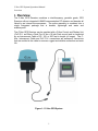
1
C-Nav™ GPS System Operations Manual Revision: 2.2 Date: December, 2004 C&C Technologies, Inc., GPS Services Group, 730 E. Kaliste Saloom Road, Lafayette, LA 70508 U.S.A. http://www.cctechnol.com CNAV GPS System Operations Manual (This page intentionally left blank) ii C-Nav GPS System Operations Manual Preface Release Notice This is the Revision 2.2, December, 2004 release of the C-Nav GPS System Operations Manual. Revision History Date 10/10/01 various Changes 12/20/02 Version 1.0 1.1 thru 1.7 1.8 04/26/03 1.9 General Chapter 4 Appendix B Appendix D 09/10/03 2.0 08/05/04 2.1 General Section 3 Section 4 Appendix D Section 6 Section 7 12/30/04 2.2 Multiple General Comments First Release of C-Nav GPS System Operations Manual General updates and edit Updated Inmarsat L-Band frequency listing for C-Nav Corrections delivery Updated reference to S.B.A.S. mode (ie; WAAS and EGNOS) Updated CnC D.U. Status Menu Display Information (#3201 & 3202) Updated CnC D.U. Default Setting Information Table B.2 Added TRIN ASCII Data message format definition as available from the Ver: 1.1.5 CnC D.U. firmware release Update of Manual for CnC D.U. firmware release Ver: 1.2.0 Added CnC D.U. DP ‘xxGGA’ NMEA message format definition - includes how to set up the position filter mechanism for the DP ‘xxGGA’ message output control Corrected and Updated Table 6.3 - Added ‘How to Record RAW GPS ‘binary’ data using StarUtil Updated Information on 24 hour GRACE DAY period activation i C-Nav GPS System Operations Manual Preface Trademarks C&C Technologies and the C-Nav logo are trademarks of C&C Technologies, Inc. C-Nav is a trademark of C&C Technologies, Inc. StarFire, StarLight, SF-2000R, and NCT-200D are trademarks of NAVCOM Technology, Inc. GALAPAGO is a trademark of C & C Technologies, Inc. Rabbit Field Utility is a copyright of Zworld, Inc. Microsoft, MS-DOS, Windows, Windows 95, Windows 98, Windows 2000, and Windows NT are registered trademarks or trademarks of Microsoft Corporation. All other brand names are trademarks of their respective holders. Disclaimer of Warranty EXCEPT AS INDICATED IN “LIMITED WARRANTY” HEREIN, C&C TECHNOLOGIES, SOFTWARE, FIRMWARE AND DOCUMENTATION IS PROVIDED “AS IS” AND WITHOUT EXPRESS OR LIMITED WARRANTY OF ANY KIND BY EITHER C&C TECHNOLOGIES, INC., OR ANYONE WHO HAS BEEN INVOLVED IN ITS CREATION, PRODUCTION, OR DISTRIBUTION INCLUDING BUT NOT LIMITED TO THE IMPLIED WARRANTIES OF MERCHANTABILITY AND FITNESS FOR A PARTICULAR PURPOSE. THE ENTIRE RISK, AS TO THE QUALITY AND PERFORMANCE OF THE C&C TECHNOLOGIES HARDWARE, SOFTWARE, FIRMWARE AND DOCUMENTATION, IS WITH YOU. SOME STATES DO NOT ALLOW THE EXCLUSION OF IMPLIED WARRANTIES, SO THE ABOVE EXCLUSION MAY NOT APPLY TO YOU. Limitation of Liability IN NO EVENT WILL C&C TECHNOLOGIES, INC., OR ANY PERSON INVOLVED IN THE CREATION, PRODUCTION, OR DISTRIBUTION OF THE C&C TECHNOLOGIES SOFTWARE BE LIABLE TO YOU ON ACCOUNT OF ANY CLAIM FOR ANY DAMAGES, INCLUDING ANY LOST PROFITS, LOST SAVINGS, OR OTHER SPECIAL, INCIDENTAL, CONSEQUENTIAL, OR EXEMPLARY DAMAGES, INCLUDING BUT NOT LIMITED TO ANY DAMAGES ASSESSED AGAINST OR PAID BY YOU TO ANY THIRD PARTY, RISING OUT OF THE USE, LIABILITY TO USE, QUALITY OR PERFORMANCE OF SUCH C&C TECHNOLOGIES SOFTWARE, HARDWARE, AND DOCUMENTATION, EVEN IF C&C TECHNOLOGIES, INC., OR ANY SUCH PERSON OR ENTITY HAS BEEN ADVISED OF THE POSSIBILITY OF DAMAGES, OR FOR ANY CLAIM BY ANY OTHER PARTY. SOME STATES DO NOT ALLOW THE LIMITATION OR EXCLUSION OF LIABILITY FOR INCIDENTAL OR CONSEQUENTIAL DAMAGES SO; THE ABOVE LIMITATIONS MAY NOT APPLY TO YOU. See service agreement for specific warranty information. ii C-Nav GPS System Operations Manual Preface FCC Notice Class A Computing Device This unit generates, uses and can radiate radio RF energy. This equipment has been tested and is found in compliance with limits for a Class A digital device, pursuant to Part 15 of the Federal Communication Commission Rules. These limits are designed to provide protection against inference when the equipment is operated in a commercial environment. Improper installation and operation of this equipment may cause harmful interference to radio communications. Operation in a residential area is likely to cause harmful interference, in which the end user will be required to correct the interference at his own expense. GPS Service. Selected Availability (S/A code) has been disabled. This offers increased accuracy. The United States government has stated that present GPS users do so at their own risk. The Government may at any time end or change operation of these satellites without warning. U.S. Department of Commerce Limits Requirements that all exportable GPS products contain performance limitations so that they cannot be used to threatens the security of the United Stated. Access to satellite measurements and navigation results will be limited from display and recordable output when predetermined values of velocity and altitude are exceeded, known as the COCOM limits. These threshold values are far in excess of the normal and expected operation parameters of the C-Nav GPS System. COCOM Limits The U.S. Department of Commerce requires that all exportable GPS products contain performance limitations so that they cannot be used in a manner that could threaten the security of the United States. The following limitations are implemented on the C-Nav GPS Receiver. Immediate access to satellite measurements and navigation results is disabled when the receiver’s velocity is computed to be greater than 1000 knots (515 meters per second), or its altitude is computed to be above 18,000 meters. The receiver continuously resets until the COCOM situation is cleared. iii C-Nav GPS System Operations Manual Preface About This Manual Welcome to the C-Nav GPS System Operations Manual. This manual describes how to install and configure the C-Nav GPS System. It includes step-by-step instructions for installing C-Nav GPS Receiver and guidelines for using the C-Nav Control (CnC) Display Unit with its LCD screen display and keypad to view and configure the C-Nav GPS Receiver operating parameters. Also included are guidelines for interfacing the C-Nav GPS System to a PC and other user equipment via the RS232 interfaces of the CnC Display Unit, information about the selection of NMEA messages supported by the C-Nav GPS Receiver, and connector pin-out diagrams for the various cable connections. Scope and Audience Even if you have used other NAVSTAR Global Positioning System (GPS) products before, we recommend that you spend some time reading this manual to learn about the special features of the C-Nav GPS System product. If you are not familiar with GPS, there are many sources that you can read, contact C&C Technologies for assistance. The following sections provide a guide to this manual, as well as to other documentation that you may have received with this product. Organization This manual contains the following: • Chapter 1, Overview, provides a brief overview of GPS and C-Nav system components. • Chapter 2, Installing the C-Nav GPS Receiver and C-Nav Control Display Unit. • Chapter 3, Getting Started, gives basic overview for using the C-Nav GPS System. • Chapter 4, C-Nav Control Display Unit Detailed Menu Operation. • Chapter 5, C-Nav GPS Receiver RS232 Serial Interface Commands (and Messages). • Chapter 6, Configuring the C-Nav GPS Receiver. • Chapter 7, Troubleshooting, gives guidelines for solving potential problems. • Appendix A, Specifications, identifies the physical characteristics and general specifications. • Appendix B, Receiver Defaults, contains the default settings for the C-Nav GPS System. • Appendix C, Cables and Connectors, includes pin-out diagrams for the standard and optional cables. • Appendix D, NMEA-0183 Sentences, describes the structure of NMEA messages generated by the C-Nav GPS Receiver/ System and the information included in their implementation. • Appendix E, Activating the C-Nav Subscription Service, provides step-by-step instructions for activating an L-Band communication satellite correction service by use of a 24-digit activation code, how to enter the code into the CNav GPS Receiver. • Appendix F, Software Applications, explains how to use additional software applications, allow recording of GPS RAW Observations for conversion to a RINEX data file and use of GALAPAGO and RFU software utilities that allow the user to update operating firmware. • Appendix G, C-Nav activation code action and feed back forms. • Appendix H, Raw GPS Binary Measurement Message Format/Definition. • List of Figures • List of Tables iv C-Nav GPS System Operations Manual Preface Related Information The following sections discuss other sources of information that introduce, extend, or update this manual. Reader Comment Form Thank you for purchasing this product. We would appreciate feedback about the documentation. Use the reader comment form in Appendix G of this manual or, if this is not available, send comments and suggestions to the address at the front of this manual. All comments and suggestions become the property of C&C Technologies, Inc. Warnings, Cautions, Notes, and Tips Warnings, cautions, notes, and tips draw attention to important information and indicate its nature and purpose. Warning – Warnings alert you to situations that could cause personal injury or unrecoverable data loss. Caution – Cautions alert you to situations that could cause hardware damage or software error. Note – Notes give additional significant information about the subject to increase your knowledge, or guide your actions. Tip – Tips indicate a shortcut or other time- or labor-saving hint that can help you make better use of the product. Update Notes There is a warranty activation sheet with this product. Send it in to receive update notes automatically as they become available. These contain important information about software and hardware changes. Contact C&C Technologies, Inc., for more information about the support agreement contracts for software and firmware. Other Information This section lists sources that provide other useful information. World Wide Web (WWW) Site Visit C&C Technologies at our site on the World Wide Web @ http://www.cctechnol.com/ v C-Nav GPS System Operations Manual Preface Contact Information If you have a problem and cannot find the information you need during installation or operation of the C-Nav GPS System product or documentation, contact C&C Technologies, Inc. C-Nav Support Group. The contact information is as follows:Phone: (+1) 337-261-0660 USA (24/7 support) Fax: (+1) 337-261-0192 USA Phones are answered 24 hours, 7 days a week, with on-call technical support engineers available (at short notice). Email: [email protected] WEB: http://www.cctechnol.com/cnav - C-Nav Support/GPS Services Group Note – C-Nav Support's technical group ‘standard’ work hours are 7am to 5pm, Monday through Friday Central USA Standard Time for immediate contact in the USA. In addition, our regional offices can provide first line support for the C-Nav GP System. To expedite the support process, please have following information available: 1. The product type and model number(s) 2. The Serial number(s) 3. The software or firmware version number(s) 4. The LAT/LON position of operation 5. Your specific question or problem. Please detail background information, such as the configuration of your system, the actual receiver parameters of operation, and the exact type, make, and configuration of your computer and navigation software in use. If you have received error messages, please specify the exact wording. If you need to send a data file along with your inquiry, please compress the file using PKZIP or WINZIP Software and name the file with the extension .ZIP. Use one of the following methods to send the data file: • Attach the file(s) to your email inquiry to [email protected]. The file attachments must be less than 2Mbyte in size in order for them to be received via the C&C Technologies, Inc. mail-server. • Place the file on an open FTP site and include the 'link' to the filename in your email (or telephone) inquiry so that C-Nav Support can retrieve the file(s). In the event that your equipment requires service, we recommend that you contact either your regional agent or C&C Technologies, Inc., GPS Services Group to obtain a Return Material Authorization (RMA) number before returning any items or product. You do need to provide a fault or failure description before C&C Technologies, Inc., will issue an RMA number that must be used to identify and track all returned equipment. Note – Please see the Frequently Asked Questions (FAQ) on our WEB Site (ie; http://www.cctechnol.com/cnav_faq.php ) or in Section 7 of this manual. vi C-Nav GPS System Operations Manual Contents Contents FCC Notice ................................................................................................................... iii Class A Computing Device .................................................................................... iii U.S. Department of Commerce Limits....................................................................... iii COCOM Limits............................................................................................................ iii About This Manual ...................................................................................................... iv Scope and Audience ..................................................................................................... iv Organization................................................................................................................. iv Warnings, Cautions, Notes, and Tips.......................................................................... v Contact Information .................................................................................................... vi 1. Overview......................................................................... 1 1.1 Differential GPS Positioning .................................................................... 3 1.2 C-Nav GcGPS Corrections ....................................................................... 4 1.2.1 RTG - Real-Time GYPSY ....................................................................... 5 1.2.1.1. RTNT (Real-Time Net Transfer) .................................................... 5 1.2.1.1. RTG Data Collection........................................................................ 6 1.2.1.2. RTG Orbit Determination and Clock Estimation.......................... 6 1.2.1.3. RTG Global Differential Correctors ............................................... 7 1.2.2 WCT - Wide Area Correction Transform .............................................. 7 1.2.2.1. WCT Ground Reference Network.................................................. 9 1.2.3 Sources of GPS Error............................................................................ 10 1.2.3.1. Ephemeris Errors - User Independent ........................................ 11 1.2.3.2. Satellite Clock Errors - User Independent.................................. 11 1.2.3.3. Ionosphere Errors - User Independent ....................................... 12 1.2.3.4. Troposphere Errors - User Independent .................................... 13 1.2.3.5. Multipath Errors - User Dependent.............................................. 13 1.2.3.6. Receiver Errors - User Dependent .............................................. 13 Measuring GPS Accuracy ....................................................................... 14 1.3 1.3.1 GPS Positioning ..................................................................................... 14 1.3.2 Autonomous GPS Positioning.............................................................. 15 1.3.3 C-Nav GcGPS Positioning.................................................................... 15 2. Installing the C-Nav GPS System............................... 17 2.1 Unpacking ..................................................................................................... 17 2.2 Inspection ...................................................................................................... 17 2.3 Serial Numbers ........................................................................................... 17 vii C-Nav GPS System Operations Manual 2.4 Contents Controls and connectors .......................................................................... 17 2.5 Installation Guidelines ............................................................................. 18 2.6 Routing and Connection of the Interconnect Cable ...................... 19 2.7 Connecting External Devices ................................................................. 20 2.8 DC Power Supply Requirements.......................................................... 21 3. Getting Started............................................................. 23 3.1 Using the C-Nav Control Display Unit Front Panel Keypad..................... 23 3.2 Using the C-Nav Control Display Unit - Overview........................ 24 3.3 The HOME Menu Structure (1000’s) ............................................... 25 3.4 The OPTION Menu Structure (4000’s) ............................................. 26 3.5 The STATUS Menu Structure (2000’s) ............................................. 27 3.6 The CONFIGURATION Menu Structure (3000’s) ....................... 28 4. C-Nav Control Display Unit Menu Details.................. 29 4.1 The C-Nav Control Display Unit hardware features: -............................... 29 4.2 CnC D.U. Home Menu ............................................................................. 31 4.2.1 Operation Information Screen .............................................................. 31 4.2.2 Position Information Screen ................................................................. 33 4.2.3 C-Nav Authorization Screen ................................................................. 33 4.2.4 C-Nav Authorization Information Screen............................................ 34 4.2.5 C&C Contact Information Screen ........................................................ 36 4.3 CnC D.U. Alarm Menu ............................................................................ 37 4.3.1 CnC D.U. Alarm Messages.............................................................................. 38 CnC D.U. Status Menu ............................................................................ 40 4.4 4.4.1 C-Nav GPS Status Menu ...................................................................... 40 4.4.1.1. Latitude/Longitude Status Menu .................................................. 40 4.4.1.2. Height Above Ellipsoid/Mean Sea Level Status Menu............. 41 4.4.1.3. Speed Over Ground/Course Over Ground Status Menu......... 41 4.4.1.4. GPS Satellites in Use Status Menu............................................. 42 4.4.1.5. SV Channels Status Menu............................................................ 42 4.4.1.6. Dilution Of Precision Status Menu............................................... 43 4.4.2 Correction Status Menu ........................................................................ 44 4.4.2.1. Correction Satellite Status Menu ................................................. 44 4.4.2.2. Correction Tracking Status Menu ................................................ 45 4.4.2.3. Correction Signal Status Menu .................................................... 45 4.4.2.4. Correction Age Status Menu ........................................................ 46 4.4.2.5. RTG Status Menu .......................................................................... 46 4.4.2.6. WCT Status Menu.......................................................................... 47 viii C-Nav GPS System Operations Manual Contents 4.4.2.7. S.B.A.S Status Menu ..................................................................... 47 4.4.2.8. RTCM Status Menu ....................................................................... 48 4.4.2.9. Authorization Code Status Menu ................................................. 48 4.4.2.10. Authorization Code Result Menu ................................................. 49 4.4.3 Receiver Status Menu ........................................................................... 49 4.4.3.1. Universal Time Coordinate Status Menu.................................... 50 4.4.3.2. GPS Week and Seconds of the Week Status Menu ................ 50 4.4.3.3. RF Hardware Version Status Menu ............................................ 51 4.4.3.4. SF Version Status Menu ............................................................... 51 4.4.3.5. GPS Receiver Version Status Menu ........................................... 52 4.4.3.6. Software Timestamp Version Status Menu................................ 52 4.4.3.7. GPS Software Version Status Menu ........................................... 52 4.4.3.8. C-Nav DC Power Status Menu .................................................... 53 4.4.3.9. Analog to Digital converters voltage Status Menu .................... 53 4.5 CnC D.U. Configuration Menu ............................................................. 54 4.5.1 GPS NAV Configuration Menu............................................................. 54 4.5.1.1. Restore Defaults Configuration Menu......................................... 55 4.5.1.2. Elevation Mask Configuration Menu ........................................... 56 4.5.1.3. Operation Mode Configuration Menu.......................................... 57 4.5.1.4. Height Above Ellipsoid for Manual 2D Configuration Menu .... 58 4.5.1.5. DOP Mask Configuration Menu ................................................... 60 4.5.1.6. Correction Age Configuration Menu............................................ 61 4.5.1.7. GPS Mode Configuration Menu ................................................... 62 4.5.1.8. GPS Mode Configuration Menu ................................................... 63 4.5.2 Correction Configuration Menu ............................................................ 64 4.5.2.1. Communication Satellite Configuration Menu ........................... 65 4.5.2.2. Authorization Code Configuration Menu .................................... 67 4.5.2.3. Grace Day Configuration Menu ................................................... 68 4.5.2.4. RTG Configuration Menu .............................................................. 70 4.5.2.5. WCT Configuration Menu ............................................................. 71 4.5.2.6. SBAS Configuration Menu............................................................ 72 4.5.2.7. RTCM Configuration Menu ........................................................... 73 4.5.3 Port Configuration Menu ....................................................................... 74 4.5.3.1. NMEA Data Port Baud Rate Configuration Menu..................... 75 4.5.3.2. RTCM Data Port Baud Rate Configuration Menu ..................... 76 4.5.3.3. GGA NMEA Message Configuration Menu................................ 77 4.5.3.4. GLL NMEA Message Configuration Menu ................................. 78 4.5.3.5. GSA NMEA Message Configuration Menu ................................ 79 4.5.3.6. GST NMEA Message Configuration Menu ................................ 80 4.5.3.7. RMC NMEA Message Configuration Menu ............................... 81 4.5.3.8. VTG NMEA Message Configuration Menu ................................ 82 4.5.3.9. ZDA NMEA Message Configuration Menu ................................ 83 4.5.3.10. CFG ASCII Message Configuration Menu ................................. 84 4.5.3.11. NAVQ NMEA Message Configuration Menu ............................. 85 4.5.3.12. NETQ NMEA Message Configuration Menu ............................. 86 ix C-Nav GPS System Operations Manual 4.5.3.13. 4.5.3.14. 4.5.3.15. 4.5.3.16. Contents RXQ NMEA Message Configuration Menu................................ 87 SATS NMEA Message Configuration Menu .............................. 88 TRIN ASCII Message Configuration Menu ................................ 89 DP ‘xxGGA’ NMEA Message Configuration Menu ................... 90 4.6 Options Menu .................................................................................................. 91 4.6.1 CnC D.U. Option Menu Structure ........................................................ 91 4.6.1.1. Firmware Version (CnC Display Unit)............................................. 91 4.6.2 DP GGA NMEA Filter Configuration Menu ........................................ 92 4.6.2.1. CnC D.U. Filter Enable/Disable Menu ........................................ 93 4.6.2.2. CnC D.U. Filter Minimum GPS SV Configuration Menu .......... 94 4.6.2.3. CnC D.U. Filter Minimum 3D Time Configuration Menu.......... 95 4.6.2.4. CnC D.U. Filter Maximum Error Ellipse Configuration Menu .. 96 4.6.2.5. CnC D.U. Filter Maximum HDOP Configuration Menu ............ 97 4.6.3 Dump Ephemeris and Almanac Data Request Menu ...................... 98 4.6.3.1. C-Nav RAW Data Request ............................................................... 98 5. C-Nav GPS Receiver RS232 Serial Interface Commands....................................................................... 101 5.1 ASCII Fields .............................................................................................. 101 5.2 ASCII Command Details ...................................................................... 103 5.2.1 ACK ........................................................................................................ 103 5.2.2 AUTH...................................................................................................... 103 5.2.3 BAUD ..................................................................................................... 105 5.2.4 CFG ........................................................................................................ 105 5.2.5 DFLT....................................................................................................... 106 5.2.6 DBG........................................................................................................ 107 5.2.7 DIAG....................................................................................................... 107 5.2.8 MSGS..................................................................................................... 107 5.2.9 NAV ........................................................................................................ 108 5.2.10 NAVQ ..................................................................................................... 109 5.2.11 NETQ ..................................................................................................... 109 5.2.12 NMEA ..................................................................................................... 110 5.2.13 RTCM ..................................................................................................... 110 5.2.14 RTG ........................................................................................................ 111 5.2.15 RXQ........................................................................................................ 111 5.2.16 SATS ...................................................................................................... 112 5.2.17 SFCH...................................................................................................... 113 5.2.18 VER ........................................................................................................ 114 5.2.19 WAAS (or EGNOS).............................................................................. 114 5.2.20 WCT ....................................................................................................... 115 6. Configuring the C-Nav GPS Receiver ...................... 117 6.1 Elevation Mask ......................................................................................... 117 6.2 DOP Limits................................................................................................. 117 x C-Nav GPS System Operations Manual Contents 6.3 GPS Operation Mode ............................................................................. 118 6.4 Manual 2D Mode...................................................................................... 118 6.5 Correction Signal Source ...................................................................... 119 6.6 C-Nav L-Band Correction Signal Frequency ................................ 120 6.7 Correction Signal Age (‘Coasting Period’) ..................................... 121 6.8 Navigation Rate ........................................................................................ 121 6.9 C-Nav GPS Receiver ASCII Data Output Messages .................. 122 6.10 RTCM Binary Corrections................................................................... 123 6.11 BAUD Rates ............................................................................................... 123 6.12 DIAG/DBG Messages ............................................................................. 123 7. Troubleshooting ........................................................ 125 7.1 Increasing GPS Accuracy ........................................................................... 125 7.2 Intermittent GPS Loss.................................................................................. 126 7.3 Power Lines and Strong Magnetic Fields ................................................... 126 7.4 Choosing a Location ................................................................................... 127 7.5 Checking for Cable Failure.......................................................................... 127 7.6 Why GcGPS Works In Some Places But Not Others?............................. 127 7.7 Why Satellite Signals are Lost in Some Locations?................................... 128 7.8 Verifying NMEA messages are being Output ............................................ 128 7.9 How is the checksum calculated in NMEA 0183?...................................... 128 7.10 Interfacing the RTCM With Other GPS Receivers................................... 128 7.11 Verifying RTCM messages are being Output ............................................ 129 7.12 Enabling C-Nav RTCM Corrections as an output .................................... 129 7.13 Loss of Settings When the Unit is Powered Off ....................................... 129 7.14 Restoring the Receiver to Factory Defaults................................................ 130 7.15 The CnC D.U. is powered on but nothing happens and no characters are displayed on the LCD panel? ................................................................................... 130 7.16 What information do I need to provide to the C-Nav Support group to help resolve my question?................................................................................................. 131 7.17 How to record RAW GPS ‘binary’ data using StarUtil............................ 132 7.18 Quick Guide Fault Analysis ......................................................................... 136 xi C-Nav GPS System Operations Manual Contents A. C-Nav GPS System Specifications........................... 137 A.1 C-Nav GPS Receiver Specifications .................................................. 137 A.2 CnC D.U. Desk Top Display Unit Specifications .......................... 138 A.3 CnC D.U. 19-Inch Rack Display Unit Specifications .................. 139 B. C-Nav GPS System Defaults..................................... 141 B.1 C-Nav GPS Receiver Defaults ............................................................. 141 B.2 CnC D.U. Defaults ................................................................................... 142 C. Cables and Connectors............................................. 143 C.1 C-Nav Port Connector ........................................................................... 143 C.2 CnC D.U. to C-Nav Connector............................................................ 144 C.3 C-Nav Interconnect Cable .................................................................... 145 C.4 CnC D.U. NMEA Connector ............................................................... 146 C.5 CnC D.U. RTCM Connector ............................................................... 147 C.6 CnC D.U. RAW GPS Data Connector ............................................. 148 C.7 C-Nav Control Display Unit Power Connector............................. 149 C.8 C-Nav Data / Power ‘Bypass’ Y-Cable ............................................ 150 C.9 20ft DC Power Cable .............................................................................. 151 C.10 RS232 to RS422 ‘Inline’ Amplifier Converter .......................... 152 C.11 CnC Desk Top Display Unit Back Panel ..................................... 154 C.12 Desk Top CnC D.U. Wiring Diagram .......................................... 155 C.12 Desk Top CnC D.U. Parts List ........................................................ 156 C.13 C-Nav GPS Receiver ‘base’ connector wiring diagram ......... 157 C.14 Data/Power ‘Bypass’ Y-Cable Wiring Diagram ....................... 158 C.15 C-Nav Control Display Unit 19-in Rack Mount ....................... 159 D. NMEA-0183 Sentences .............................................. 161 D.1 NMEA-0183 Sentence Structure ........................................................ 162 D.1.1 Symbols and Delimiters ...................................................................... 162 D.1.2 Address Field ........................................................................................ 162 D.1.2.1 Approved NMEA-0183 Address Fields ......................................... 163 D.1.2.2 Proprietary Address Fields ............................................................. 163 D.1.3 Data Field .............................................................................................. 164 xii C-Nav GPS System Operations Manual Contents D.1.4 D.1.5 Check Sum Field .................................................................................. 165 Null Fields.............................................................................................. 165 D.2 GGA NMEA Sentence ............................................................................ 166 D.3 GLL NMEA Sentence ............................................................................ 168 D.4 GSA NMEA Sentence ............................................................................. 169 D.5 GST NMEA Sentence ............................................................................. 170 D.6 RMC NMEA Sentence ........................................................................... 172 D.7 VTG NMEA Sentence ............................................................................ 173 D.8 ZDA NMEA Sentence ............................................................................ 174 D.9 NAVQ NMEA Compliant Sentence .................................................. 175 D.10 NETQ Sentence .................................................................................... 176 D.11 RXQ NMEA Compliant Sentence ................................................. 176 D.12 SATS NMEA Compliant Sentence ................................................ 177 D.13 TRIN ASCII Message Sentence (Non-NMEA Compliant) ... 178 D.14 DP ‘xxGGA’ NMEA Compliant Sentence .................................. 181 E. Activating/Deactivating the C-Nav Subscription Service ............................................................................. 183 E.1 Subscription / Authorization Code .................................................... 183 E.1.1 E.1.2 E.1.3 E.1.4 Authorization Code Verification.......................................................... 183 Reviewing existing Authorization Code Service.............................. 183 Activating a new Authorization Code ................................................ 184 Early Termination (or cancellation) of Subscription Service ................. 185 F. C-Nav Software Applications.................................... 187 F.1 C-Nav Software Utilities CD Auto Install ....................................... 188 F.2 Satellite Calculator .................................................................................. 189 F.3 StarUTIL Software.................................................................................. 191 F.3.1 F.3.2 F.3.3 F.3.4 F.4 STARTUP AND PORT SELECTION ................................................ 193 ‘Binary’ OUTPUT MESSAGE INFORMATION............................... 194 SETTING UP LOGGING..................................................................... 197 StarUtil HELP........................................................................................ 201 Converting RAW GPS data files to RINEX format .................... 202 F.4.1 Running RINEX.EXE program ........................................................... 203 xiii C-Nav GPS System Operations Manual Contents F.5 GALAPAGO.............................................................................................. 205 F.5.1 Software installation............................................................................. 205 F.5.2 File Menu ............................................................................................... 208 F.5.3 Setup Menu ........................................................................................... 210 F.5.3.1 Setup - Open Flash.......................................................................... 210 F.5.3.2 Setup - Select Port ........................................................................... 211 F.5.3.3 Setup - Configure ............................................................................. 212 F.5.3.4 Setup - Begin Update ...................................................................... 213 F.5.4 View Menu............................................................................................. 215 F.5.4.1 View – Settings ............................................................................. 216 F.5.4.2 View – Hardware .......................................................................... 216 F.5.4.3 View – Voltages............................................................................ 217 F.5.5 Help Menu ............................................................................................. 217 F.5.6 Getting Started Quick Guide .............................................................. 219 F.6 RABBIT u-Processor Field Utility ..................................................... 220 F.6.1 F.6.2 Install RFU Icon .................................................................................... 220 Firmware Upload Preparation ............................................................ 221 G. Forms.......................................................................... 225 H Raw GPS ‘Binary’ Data Format................................. 229 0xB0 – Raw Measurement Data Block.................................................................... 229 0x81 - Packed Ephemeris Data ................................................................................ 231 0xB1 – Position, Velocity, Time, and Quality Data Block..................................... 234 LIST of FIGURES ............................................................. 237 LIST of TABLES............................................................... 243 xiv C-Nav GPS System Operations Manual Contents (This page intentionally left blank) xv C-Nav GPS System Operations Manual Overview 1 1. Overview The C-Nav GPS Receiver combines a dual-frequency, geodetic grade, GPS Receiver with an integrated L-BAND communication RF detector and decoder all linked by an internal microprocessor. The entire assembly is combined into a single integrated package that is durable, lightweight and water and weatherproof. The C-Nav GPS Receiver can be supplied with a C-Nav Control and Display Unit (CnC D.U. as Either a Desk-Top Or as a 19 inch Rack mount) and is connected by an Interconnect Cable of 50, 100, or 200 feet in length (or longer). The CNav, Interconnect Cable and CnC D.U. connections are waterproof connectors that are molded to the cable to ensure a rugged and reliable connection and work life. Figure 1-1 C-Nav GPS System 1 C-Nav GPS System Operations Manual Overview 1 The major components of the C-Nav GPS Receiver unit are: A multi-function antenna assembly is used which is capable of receiving the L1 and L2 GPS frequencies as well as the StarFire GcGPS corrections that are transmitted over the Inmarsat L-BAND frequency band. The gain pattern of this antenna is designed to be relatively constant even at lower elevations. This allows for an efficient link budget when the unit is operated at higher latitudes where the elevation of the geo-stationary communication satellite is low and close to the horizon. Connections for the RS-232 serial interfaces of the C-Nav GPS Receiver unit are provided through a sealed 8-pin waterproof connector. Power is supplied to the C-Nav GPS Receiver unit along with RS232 interface signals and a CAN Bus through this single 8-pin connector. The C-Nav GPS Receiver system provides for accurate GPS position information to be computed for display and use by the user by means of the C-Nav Control Display Unit (CnC D.U.). The CnC D.U. can be supplied in either a Desk-Top or 19-inch Rack mount package design. The CnC D.U. supplies the required D.C. power voltage for the C-Nav GPS Receiver unit via the Interconnect cable. The CnC D.U. also provides for electronic RS232 interface of ASCII NMEA information for output, for use on a wide variety of electronic interfaces and devices, via DB-9 DTE RS232 serial interface connection port(s). The C-Nav GPS System provides an optional output of RTCM psuedorange GNSS Differential GPS Corrections (Type 1 - PRC only) and GPS Reference Station Parameters (Type 3 - C-Nav PVT solution ECEF / WGS84 coordinates) messages via the second RS232 serial interface (of the C-Nav Control Display Unit – CnC D.U.) for use by 3rd party DGPS capable receiver equipment. These RTCM (Type 1 and Type 3) binary messages are separated from the general C-Nav GPS Receiver ASCII and Binary RS232 data packets, as output from the C-Nav GPS Receiver (via the Diagnostic Data Port) by the CnC D.U. and are provided to the user by use of the 2nd RS232 (RTCM labeled) data port connection. Finally, RAW GPS observation information can be collected from the C-Nav GPS Receiver system for recording and analysis. The RAW GPS observation information can be converted to RINEX ASCII data (observation and navigation) file format as and when required. Information is provided (Appendix H) on the format of the RAW GPS ‘binary’ observation message format to allow ‘the user’ to decode the Dual frequency (L1/L2 code a phase measurements) observations and re-format to produce a P2-94 data record set. 2 C-Nav GPS System Operations Manual Overview 1 1.1 Differential GPS Positioning Traditional Differential GPS (DGPS) relies on the concept that the errors in the position at one location are similar to those for all locations within a given (local) area. By recording GPS measurements at a point with known coordinates, the local GPS observation errors can be quantified and one psuedorange correction for each GPS satellite observation can be computed. By transmitting these psuedorange corrections to remote mobile users and applying them in real-time (typically less than 30 seconds), the remote mobile user accuracy of GPS for instantaneous horizontal positioning is reduced to less than 5 meters (and even sub-meter with modern commercial survey grade GPS receivers) 95% of the time. DGPS is now a well-practiced technique for areas such as Navigation, onshore and offshore Surveying and Mapping etc. In traditional DGPS psuedorange corrections are generated at a reference station. By transmitting these individual corrections for satellites all in view the mobile user can apply the psuedorange corrections for the common in view satellites observed at the mobile location. In order to minimize (as far as possible) any errors that may be introduced, it is imperative that the reference station and the mobile user are able to track the same GPS satellites and thus the maximum baseline distance is one limiting factor. Another is that the accuracy of the mobile user position will be degraded by the baseline distance separation between the reference station and the mobile user increases. This is due to geographic spatial de-correlation errors introduced by the different ionosphere delays and GPS satellite orbit differences between the DGPS Reference Site and each individual mobile DGPS users position. The reference station (or network) computes not only a Psuedorange Correction (PRC) for each satellite, but a Range Rate Correction (RRC) is also computed. Thus, the mobile user is able to model the time varying characteristics of the psuedorange corrections over the time intervals in which they are 'periodically' generated at the reference station and applied at the mobile location (the age of correction). In summary, DGPS psuedorange corrections combine together into one correction all the errors produced by the GPS satellite Ephemeris, Clock, and earth atmospheric delays at one and the same time for the reference station position. 3 C-Nav GPS System Operations Manual Overview 1 1.2 C-Nav GcGPS Corrections At a conceptual level, the C-Nav GcGPS corrections are similar to other widearea DGPS systems such as the Federal Aviation Administration’s Wide Area Augmentation System (WAAS). This is not at all like traditional DGPS. The C-Nav GPS Receiver can accept two (2) different GcGPS correction service message formats. The first is the method called the Wide area Correction Transform (WCT) correction service. The WCT reference site networks consist of a number of reference/monitor sites distributed across several continental areas. These are the U.S., Europe, South America and Australia. Each WCT reference site sends dual frequency observables for all satellites in view as well as system integrity information to two redundant networkprocessing hubs (NPH) via terrestrial communication links. The NPHs combine the GPS RAW observables from all of the WCT sites, in a particular continental region and generate a single set of on ‘refraction corrected’ psuedorange corrections for each GPS SV visible to the WCT ‘regional’ network. The WCT corrections are sent, via landlines, to the land earth station for uplink to the geo-stationary L-band communications satellite for broadcast to suitable equipped users throughout the continental service area. The second is called the Real Time Gipsy (RTG) correction service. The RTG network comprises of a global set of reference/monitor sites distributed around the entire world. These sites are part of the ITRF global network. Again, the NPHs collect and process the dual frequency GPS RAW observables from all of the Real-Time Gipsy (RTG) ITRF sites, for the entire world, and generate a ‘refraction corrected’ Orbit correction (to the broadcast ephemeris) and a clock correction for each operational GPS SV in orbit. Again, the corrections are sent, via landlines, to the land earth station for uplink to the geo-stationary, L-band communications satellite for broadcast to suitable equipped users throughout the Inmarsat global service areas. The C-Nav, dual-frequency, GPS user equipment receives either of these corrections broadcast from the communications satellite, applies them to its own observed, refraction corrected C/A code, dual frequency observations, and performs a navigation solution. The resulting corrected GPS position; velocity and time (PVT) are output from the C-Nav equipment to other subsystems on the platform/vehicle/vessel to support the navigation positioning control requirements. 4 C-Nav GPS System Operations Manual Overview 1 The C-Nav GPS system and the correction services are optimized to exploit the use of dual frequency GPS receivers for both the reference sites and the mobile user equipment. This approach provides the ability for the user to correct, in-realtime, for their ‘local’ unique atmospheric signal delays and does not rely on atmospheric corrections values computed by a remote reference site location. 1.2.1 RTG - Real-Time GYPSY Over the past 20 years the California Institute of Technology’s Jet Propulsion Laboratory has evolved into one of the premier centers for research in precise orbit determination. The venerable GIPSY-OASIS software suite, used by research teams worldwide for geodetic analysis and orbit determination was developed at JPL. Over the last six years, the GPS group at JPL has created a system, based on adaptations and refinements of the core GIPSY algorithms, which operates in real time to produce high precision GPS corrections suitable for broadcast to navigation users. This system, called Real Time GIPSY (RTG), accurately estimates and models many parameters and error sources in the GPS satellite system using real time data received via the Internet from a worldwide network of GPS reference receivers as part of the International Terrestrial Reference Frame (ITRF) network. Two key correction factors are computed for transmission to the user’s, dual frequency, navigation receivers: 1) Clock corrections for each active GPS satellite are computed every few seconds. These corrections are based on refraction corrected measurements and are therefore optimized for dual frequency user equipment. 2) Orbit corrections for each active GPS satellite are computed every few minutes. Computation of these corrections is facilitated by measurements from the globally distributed ITRF network of reference receivers that provide observability of the orbit errors with sufficient geometry and redundancy. 1.2.1.1. RTNT (Real-Time Net Transfer) RTNT returns 5 of the 6 GPS data types: CA range, P1 and P2 ranges, and P2 phase, and either the P1 or CA phase, plus signal to noise ratios. The data is edited, smoothed, and compressed down to 21 bytes/GPS, with 17 bytes of overhead needed for time-tag, site id, navigation solution, sequence number, and status flags. For example, if a remote site tracks 10 GPS satellites, 227 bytes/sec are transmitted to a central data daemon at a Network Processing Hub (NPH) or center. Additionally, the broadcast ephemeredes are included in this transmission when new IODE numbers are observed. 5 C-Nav GPS System Operations Manual Overview 1 For improved reliability, the central data daemon keeps track of the sequence number of the packets from each remote site and may request retransmission of up to 3 missed data epochs. The primary Network Processing Hub (NPH) with its central data daemon has a twin data daemon running on another computer at the alternative Network Processing Hub (NPH). This is provided for network redundancy and to improve up-time in case of problems or failures in the network. The central data daemon relays all of its incoming GPS data to its twin also via socket communications. Should the twin no longer see any data flow, it will send out a request to the entire global network to request re-routing of the real-time data to itself. It would then serve as the central data daemon until the primary daemon is brought back on-line. The remote sites minimally have a dual-frequency GPS receiver, a computer running LINUX operating system, and connectivity to the open Internet. RTNT currently supports the data streams from Ashtech Z-12, Turbo-Rogue, and AOAACT Benchmark GPS receivers. A particular data daemon running on a computer at the remote site establishes communications with the receiver through its serial port, and places the data in a revolving buffer of shared memory. A second process that is independent of receiver type reads this shared memory and opens a socket connection to the central data daemon. The data is checked and flagged for phase breaks, and then transmitted over the socket connection. 1.2.1.1. RTG Data Collection The GPS data returned includes dual-frequency phase measurements with a resolution of 0.02 mm, and dual-frequency range measurements with a resolution of 1 mm, the receiver's solution for its time, and broadcast ephemeris information. At the NPH, these data are collected by a central data daemon that sorts the data according to time-tag, rejects duplicate transmissions, and makes requests for retransmission of missed data packets. At specified latency times of 2 and 6 seconds, all data with common epochs are written into circular shared memory buffers. In general, these two buffers contain the same data, however data that arrives late, such as retransmitted data, can still be included to the 6second latency buffer. The RTG orbit process then uses this buffer since the orbits have a slower varying behavior. The clocks on the other hand are less predictable, and hence use the 2-second latency buffer. 1.2.1.2. RTG Orbit Determination and Clock Estimation RTG reads the shared memory output of the central data daemon process. Orbit and troposphere estimates at the reference stations are computed once per minute by the orbit process, within the NPH. These estimates are then placed into another revolving buffer of shared memory so that the clock process to compute clock solutions at 1 Hz may use them. 6 C-Nav GPS System Operations Manual Overview 1 1.2.1.3. RTG Global Differential Correctors To provide corrections to the broadcast ephemeredes and broadcast clocks (IODE), the RTG process differences the orbit and clock solutions with the broadcast values. These corrections are packaged into a 560-bit message. Each message contains x,y, and z orbit corrections and meter-level clock corrections for 4 GPS satellite PRNs, and cm-level clock corrections for 32 GPS satellite PRNs. The total clock correction is the sum of meter-level correction and the cm-level correction. It requires 8 seconds for the user to initialize all 32 orbit and clock correctors. The resolution of the clock corrections is 1.5625 cm. This is 8 times better than the WAAS resolution, which is 12.5 cm. The resolution of the orbit corrections is 6.25 cm, which is the same as WAAS orbit resolution. IODE ephemeris changes are held 2 minutes after new IODEs are observed. This gives the user sufficient time to also accumulate the newest ephemeris message. In summary, the 'global' network of reference stations are used to track all GPS satellites in 'orbit' around the world and send the RAW GPS signal measurements back to the NPH. The NPH then calculates and models, in 'realtime' all of the individual GPS satellite Orbital Corrections and also the individual GPS satellite delta Clock offset values (from the broadcast ephemeredes IODE). These correctors are then transmitted to the mobile user, via geostationary communication satellites (the StarFire network). 1.2.2 WCT - Wide Area Correction Transform In the WCT application, several independent regional networks of reference/monitor sites are distributed across the various continental areas. Each site sends dual frequency observables for all GPS satellites ‘in view’ as well as system integrity information to both of the StarFire Network Processing Hubs (NPH) via terrestrial communication links. The NPHs combine the observables from all of the sites and generate a single set of wide-area corrections based on refraction corrected measurements. These corrections are broadcast to users equipped with suitable GPS receivers with L-Band signal decoders. The user equipment receives the broadcast corrections from the communications satellite, applies them to its own observed, refraction corrected GPS observations and computes a navigation solution from the resultant psuedorange measurements. The resultant corrected GPS position; velocity and time are output from the user equipment to other subsystems as required. Although similar in concept to other WADGPS architectures, the WCT system has several important features, which discriminate it from more conventional designs. Foremost is the optimization of the system to exploit the use of dual frequency GPS receivers for both the reference sites and the mobile user equipment. 7 C-Nav GPS System Operations Manual Overview 1 The algorithm used at the processing hubs to compute the C-Nav WADGPS corrections is named Wide Area Correction Transform (WCT). The WCT uses the following inputs: a) Dual frequency observables (CA code psuedoranges, L1 carrier phase, P2 code psuedoranges and L2 carrier phase) for all of the GPS satellites tracked at the ground reference network (GRN) reference receivers, at a one Hertz (1Hz), real-time rate. b) Broadcast ephemeris records from the GRN reference receivers delivered in real-time. c) A configuration file, defining the precise location (within 2 centimeters) of each GRN reference receiver antennas as determined from network solutions based on the International GPS Service (IGS) worldwide control station network. The dual frequency observables are used to form smoothed, refraction corrected psuedoranges, which are free of ionosphere delay and, due to extended smoothing techniques, virtually free of multipath errors. These are then normalized with respect to receiver clock offsets and modeled site tropospheric delays. Finally, the normalized psuedoranges for each GPS satellite are combined in a weighted average to form a single, wide area pseudorange correction for that satellite. A similar process is performed using the finite difference of the carrier phase to generate psuedorange rate corrections. The result of these computation of corrections, for all GPS satellites in view is formatted into a tightly packed, binary message and sent from the processing hub to the uplink facility for broadcast on the geo-stationary communications satellite. Because the WCT uses refraction corrected psuedoranges, the resultant WADGPS corrections are free of the errors caused by spatial decorrelation of ionospheric delays, which are inherent in single frequency corrections. When dual frequency mobile receivers are used which employ the same refraction corrected techniques, a single set of corrections can be used across the entire continental service area with uniform, high accuracy. Two major advantages result from having one consolidated set of corrections for the entire service area: a) Bandwidth requirements on the communication satellite are minimized, and the correction message efficiency is maximized. b) The correction computation algorithm, including the final weighting, is done at a centralized facility (at the network processing hub) instead of being performed by the user equipment based on location dependant models. This provides a method for improvements and upgrades to the 8 C-Nav GPS System Operations Manual Overview 1 WCT methods to be made without requiring changes to the algorithms in the mobile user equipment. 1.2.2.1. WCT Ground Reference Network Each continental region comprises of several reference/monitor sites, a processing hub and an uplink facility for the geo-stationary communication satellite. Each of the reference/monitor sites are configured with an identical set of equipment that includes: • • • • Two redundant dual frequency GPS reference receivers, which send a full set of dual frequency observables for all satellites in view to the processing hub. A complete, dual frequency WCT enabled, production GPS receiver equipment unit that serves as an independent monitor receiver. Communications Equipment (routers, ISDN modems) A remotely controlled power switch and UPS module The main communication lines used to link each reference site with the processing hub are frame relay virtual private networks (VPNs). Each VPN is backed up with an ISDN dial-up line, which is activated automatically from the processing hub in the event any VPN connection fails. The same implementation is used for the communication lines to and from the processing hubs to the communication uplink facility. Both RTG and WCT enabled, production GPS receiver equipment units are located at the reference sites. These are called monitor units which operate independently. They receive either the broadcast RTG or WCT correction signals from the communication satellites, perform their GcGPS corrected position calculation and report their positioning results back to the NPHs using the same communication lines as the reference site receivers. In addition to the RTG and WCT corrected positioning results, the monitor data includes the received signal strength of the L-Band communication satellite, packet error statistics, age of WCT corrections, signal strengths for the received GPS satellites, DOP and other parameters. This data, from all of the sites, is continuously monitored by an Alert Service Processor which automatically generates E-mail and pager messages to ‘on-call’ network service engineers in the event of a service failure. 9 C-Nav GPS System Operations Manual Overview 1 1.2.3 Sources of GPS Error GPS user range error and bias sources can be identified as follows: Ephemeris data--Errors in the location of the GPS satellite in its orbit Satellite clock--Errors in the atomic clock signal, including SA Ionosphere--Errors caused by ionospheric effects Troposphere--Errors caused by tropospheric effects Multipath--Errors caused by reflected signals entering the GPS receiver antenna Receiver--Errors in the measurement of time/range caused by thermal noise, computation accuracy, and inter-channel biases Ephemeris error is due to the small inaccuracies of the broadcast GPS message of the GPS satellite location. It is typical that the radial component of this error is the smallest: the along-track and cross-track errors are larger by an order of magnitude. The ‘line of sight’ projections of the GPS satellite positioning error affect each GPS observer differently. Satellite Clocks are fundamental to the NAVSTAR GPS system so that the oneway ranging measurement process can be accomplished. Each satellite broadcasts it’s own clock adjustment values so as to allow the user to develop accurate GPS satellite clock predictability. These satellite clock errors affect both the C/A- and P-code users in the same way, which result in a residual clock error for each GPS satellite. All GPS observers receive an identical satellite clock error. Ionosphere errors or delays are unique to the local area for each GPS observer, and are introduced due to free electrons in the ionosphere. GPS radio signals do not travel at the vacuum speed of light as they transit this region. The modulation on the signal is delayed in proportion to the number of free electrons encountered. The ionosphere is usually reasonably well behaved and stable in the temperate zones; however, near the equator or magnetic poles it can fluctuate considerably. The solar 11-year activity cycle also affects the ionosphere and causes 'scintillation' effects, which are problematical along the geo-magnetic equator when the solar cycle is at its peak. This local error can be resolved by the use of dual frequency, L1 and L2, observations by the GPS observer. Troposphere errors are deviations from the vacuum speed of light, and are unique to the local area for each GPS observer. Variations in temperature, pressure, and humidity all contribute to variations in the light speed of radio waves. Both the code and carrier will have the same delays, and use of a reliable model can reduce most of this error. 10 C-Nav GPS System Operations Manual Overview 1 Multipath Errors are caused by reflected signals entering the antenna of the GPS receiver and masking the real correlation peak. These effects tend to be more pronounced in a static receiver near large reflecting surfaces. Monitor or reference stations require special care in locating so as to avoid unacceptable errors. The first line of defense is to use the combination of antenna cut-off angle and antenna location that minimizes this problem. Receiver Errors vary from GPS unit to GPS unit. Initially most commercial GPS receivers were 'sequential', in that one or two tracking channels shared the burden of locking on to four or more satellites. As chip technology improved, it was common to place three or more tracking channels on a single inexpensive chip. As the size and cost have shrunk, techniques have improved and 'parallel' multi-channel receivers are common. Most modern GPS receivers use an alldigital design that allow very low signal noise and phase tracking design solutions. 1.2.3.1. Ephemeris Errors - User Independent Ephemeris errors result due to the broadcast GPS message for the satellite location (in its orbit) is inaccurate. It is typical that the radial component of this error is the smallest: the tangential and cross-track errors are larger by an order of magnitude. The projection of satellite positioning error along the user’s line of sight creates the most significant ranging error. Because satellite errors reflect a position prediction, they tend to grow with time from the last (GPS Ground Control Segment) station upload. It is possible that portions of any applied and deliberate Selective Availability (SA) error is added to the ephemeris as well. However, the predictions are long smooth arcs, so all errors in the ephemeris tend to be slowly changing with time. Therefore, their effect in SA is quite limited. As reported during GPS phase one, (Bowen, 1986) in 1984, for predictions of up to 24 hours, the RMS ranging error attributable to ephemeris was 2.1 meters. These errors were closely correlated with the satellite clock, as we would expect. Note that these errors are the same for both the P- and C/A-codes. 1.2.3.2. Satellite Clock Errors - User Independent Fundamental to GPS is the one-way ranging that ultimately depends on satellite clock predictability. These satellite clock errors affect both the C/A- and P-code users in the same way. The error effect is also independent of satellite direction. All GPS users measure an identical satellite clock error. A major source of apparent clock error is Selective Availability (SA), which is varied so as to be unpredictable over periods longer than about 10 minutes. The RMS value of SA is typically about 20 m in ranging, but this can change after 11 C-Nav GPS System Operations Manual Overview 1 providing appropriate notice, depending on need. The U.S. Air Force has guaranteed that the two dimensional RMS (2 DRMS) positioning error (approximately 90th percentile) will be kept to less than 100 meters. This is now a matter of U.S. federal policy and can only be changed by order of the President of the United States. [Note that SA was removed May 2, 2000 @4:05 UTC.] More interesting is the underlying accuracy of the system without any SA. The ability to predict clock behavior is a measure of clock quality. GPS uses atomic clocks (cesium and rubidium oscillators), which have stability's of about 1 part in 10E13 over a day. If a clock can be predicted to this accuracy, its error in a day (~10E5 seconds) will be about 10E-8 seconds or about 3.5 meters. The experience reported in 1984 was 4.1 meters for 24-hour predictions. Because the standard deviations of these errors were reported to grow quadratically with time, an average error of 1-2 meters for 12-hour updates is the normal expectation. 1.2.3.3. Ionosphere Errors - User Independent Because of free electrons in the ionosphere, GPS signals do not travel at the vacuum speed of light as they transit this region. The modulation on the signal is delayed in proportion to the number of free electrons encountered and is also (to first order) proportional to the inverse of the carrier frequency squared (1/f squared). The phase of the radio frequency carrier is advanced by the same amount because of these effects. Carrier-smoothed receivers should take this into account in the design of their filters. The ionosphere is usually reasonably well behaved and stable in the temperate zones; near the equator or magnetic poles it can fluctuate considerably. The solar 11-year activity cycle also affects the ionosphere and causes 'scintillation' effects, which are problematical along the geo-magnetic equator when the Solar cycle is at its peak. All users will correct the raw Psuedorange for the ionospheric delay. The simplest correction will use an internal diurnal model of these delays. For Single Frequency (L1 only) GPS users, the parameters can be updated using information in the GPS correction 'communications message'. The effective accuracy of this modeling is about 2-5 meters in ranging for users in the temperate Zones. A second technique for dual-frequency P-code receivers is to measure the signal at both frequencies and directly solve for the delay. The difference between L1 and L2 arrival times allows a direct algebraic solution. This dual-frequency technique should provide 1 meter or better of ranging accuracy, due to the ionosphere, for a well-calibrated receiver. A third technique is to rely on a near 'real-time ionosphere model' update. This should also produce corrections with accuracy's of 1-2 meters or better in the temperate zones of the world. 12 C-Nav GPS System Operations Manual Overview 1 1.2.3.4. Troposphere Errors - User Independent Another deviation from the vacuum speed of light is caused by the troposphere. Variations in temperature, pressure, and humidity all contribute to variations in the speed of light of radio waves. Both the code and carrier will have the same delays. For most users and circumstances, a simple model should be effectively accurate to about 1 meter or better. 1.2.3.5. Multipath Errors - User Dependent Multipath is the error caused by reflected signals entering the front end of the receiver and masking the real correlation peak. These effects tend to be more pronounced in a static receiver near large reflecting surfaces, where 15 meters or more in ranging error can be found in extreme cases. Monitor or reference stations require special care in locating so as to avoid unacceptable errors. The first line of defense is to use the combination of antenna cut-off angle and antenna location that minimizes this problem. A second approach is to utilize software algorithms within the receiver, which tend to minimize the impact of multipath on range tracking accuracy's. With proper location and antenna selection, the net impact to a moving user should be less than 1 meter under most circumstances. 1.2.3.6. Receiver Errors - User Dependent Initially most commercial GPS receivers were 'sequential', in that one or two tracking channels shared the burden of locking on to four or more satellites. As chip technology improved, it was common to place three or more tracking channels on a single inexpensive chip. As the size and cost have shrunk, techniques have improved and 'parallel' multi-channel receivers are common. Most modern receivers use reconstructed carrier to aid the code tracking loops. This produces a precision of better than 0.3 meter. Inter-channel bias is minimized with digital sampling and all-digital designs. The limited precision of the receiver software also contributed to errors in earlier designs, which relied on 8-bit microprocessors. With ranges to the satellites of over 20 million meters, a precision of 1 part in 10E10 or better was required. Modem microprocessors now provide such precision along with the co-requisite calculation speeds. The net result is that receiver's now contribute less than 0.5meter error in bias and less than 0.2 meters in noise. 13 C-Nav GPS System Operations Manual Overview 1 1.3 Measuring GPS Accuracy The fundamental and basic requirement of comparing geographic locations and coordinates is that the reference coordinate system and datum transformation are absolutely known. The GPS system works by using the World Geodetic Survey 1984 (WGS-84) ellipsoid and the coordinate system is in angular units of degrees (Latitude and Longitude) and the vertical height expressed in meters. Therefore when comparing coordinate values for any location in the world, such as a map position or feature, a physical survey marker or reference location, the data and observations MUST BE referenced to the same datum and coordinate system. For example, in North America, there are two different datum models in common usage. These are the North American Datum of 1927 (NAD-27) and the North American Datum of 1983 (NAD-83). A physical geographic feature on the surface will have entirely different coordinate latitude and longitude values when expressed in each of the NAD-27 and NAD-83 datum reference frames. The user is entirely responsible in ensuring that in measuring a position using the GPS system that they understands and use the WGS-84 coordinates produced by the C-Nav GPS Receiver system correctly. 1.3.1 GPS Positioning The C-Nav GPS Receiver will track and lock onto the GPS L1 (C/A Code and phase) signal and L2 (Y-Code and phase) for all satellites ‘in-view’. The C-Nav GPS Receiver will calculate a WGS-84 ‘standalone’ position using the measured psuedorange measurements for all GPS satellite that are above the user defined elevation mask and within the DOP limit values (both are able to be set by the user). The C-Nav GPS Receiver requires at least four (4) usable GPS satellites to compute a three dimensional (3D). The C-Nav GPS Receiver will yield an autonomous horizontal position accuracy of 2 to 5 meters (1 sigma), depending on the GPS satellite geometry configuration and tracking (DOP index values). If there are only three (3) GPS satellites usable, then the C-Nav GPS Receiver will compute a two dimensional (2D) horizontal position with a WGS-84 ellipsoidal height being determined from: a) The last Height Above Ellipsoid (HAE) value computed when the C-Nav GPS Receiver was able to compute a 3D position (Auto mode) b) A user defined Height Above Ellipsoid (HAE) value as entered into the CNav GPS Receiver (Manual 2D mode) 14 C-Nav GPS System Operations Manual Overview 1 1.3.2 Autonomous GPS Positioning The accuracy of the C-Nav GPS Receiver in a ‘standalone’ or autonomous GPS positioning accuracy will not be better than 2 to 5 meters (1 sigma and HDOP = 1). The biggest factor affecting an autonomous GPS position is the GPS Satellite position geometry and visibility to the user, and a quality measure of which is provided by the Dilution of Precision (DOP) indices provided by all GPS receivers. GDOP - Geometric Dilution of Precision TDOP - Time Dilution of Precision PDOP - Position Dilution of Precision HDOP - Horizontal Dilution of Precision VDOP - Vertical Dilution of Precision 1.3.3 C-Nav GcGPS Positioning The GPS satellite orbit and clock corrections are transmitted by the ‘active’ CNav Network Processing Hub (NPH) to the communication satellite land earth station (LES) for transmission and uplink through a communication satellite transponder. The correction signals are broadcast to users who are in view of the L-Band, geo-stationary, communication satellite for the region of coverage (footprint). The C-Nav subscription service GcGPS corrections are encoded and are in a format that the C-Nav GPS Receiver can receive and decode in realtime. The Real Time Gypsy (RTG) corrections are valid for the entire world. The RTG Orbit and Clock Corrections are broadcast for all of the GPS satellites in the constellation as the RTG ‘network’ of tracking stations are places around the entire world and can track each and every GPS satellite at the same time. The Wide area Correction Transform (WCT) corrections are valid for the entire continental region that the user is operating. The WCT Clock Corrections are broadcast for any of the GPS satellites visible to the continental area ‘network’ of tracking stations for the region of operation. The WCT ‘continental’ coverage areas are: • North America • South America • Europe • Australia 15 C-Nav GPS System Operations Manual Overview 1 The satellite correction signals can be lost, just like the GPS satellite signals, by any local blocking or masking medium. The C-Nav correction signals require a direct line of sight from the C-Nav GPS Receiver antenna location to the location of the communication satellite geo-stationary location. Any building, structure, tree, hill or mountain in the path of the correction signal will cause loss of the correction signals. Additional attenuation of the signal can be caused by wet tree canopy or vegetation and heavy rain. Also, high power RF sources such as radar and microwave transmitters affect both GPS signals and correction signals. Overhead power lines usually do not cause problems, but again, if a noisy RF environment is encountered, the GPS satellite and geo-stationary communication satellite correction signals can be attenuated. Figure 1-2 C-Nav GcGPS Network 16 C-Nav GPS System Operations Manual Installing the C-Nav GPS System 2 2. Installing the C-Nav GPS System This chapter outlines the unpacking, inspection, installation, and connection of the C-Nav GPS Receiver, the C-Nav Control and Display Unit (if required), the Interconnect Cable, and associated accessories. 2.1 Unpacking The standard C-Nav GPS System ‘bundle’ comprises the following items: 1 C-Nav GPS Receiver 1 C-Nav Control Display Unit (CnC D.U.) – either Desk-Top Mount or 19-inch Rack Mount 1 Interconnect Cable (user specified length) 1 C-Nav GPS Receiver Data and Power Y-Cable (Bypass Cable) 1 20ft DC Power Cable w/inline fuse 1 28volt d.c. Universal Power Supply 1 C-Nav Operations Manual 1 Set Software Utilities (StarUtil, Rinex, Galapago, RFU etc…) CD-ROM 1 Mast stub adaptor ¾ - inch BSP thread The shipment could include one or more cartons, depending on the number of accessories ordered. Open the shipping carton(s) and make sure that all of the components are included. 2.2 Inspection Inspect the shipping containers. If in poor condition when received examine the equipment for visible damage. If any damage is found, immediately notify the carrier and C&C Technologies, Inc. service Department at [email protected] or at (+1)337-261-0660. Keep all packing material for the carrier’s inspection. 2.3 Serial Numbers Record the serial numbers for identification purposes before installation in case the instrument is lost or stolen. The C-Nav GPS Receiver serial number is located on the label on the base, and the C-Nav Control Display Unit (CnC D.U. Desk-Top or 19-inch Rack)serial number is located on the back cover label. 2.4 Controls and connectors The C-Nav GPS Receiver is enclosed in a waterproof black aluminum with a blue hard plastic housing. The C-Nav GPS Receiver I/F connection is an 8-pin male, marine type waterproof connector. The C-Nav Control Display Unit (CnC D.U. Desk-Top or 19-inch Rack)has one 8-pin female connector pigtail, three DB-9 RS232 female connectors, an optional Cat-5 connector and a DC Power connector. The CnC D.U. also has a 4x20 character LCD display and a 2x6 keypad. 17 C-Nav GPS System Operations Manual 2 Installing the C-Nav GPS System 2.5 Installation Guidelines The C-Nav GPS Receiver is designed to be mounted on a mast head or mounting pole by use of the ¾ inch threaded adapter ‘stub’ that forms an integral part of the base housing. Choose a location for the C-Nav GPS Receiver that is safe from damage during normal operations. If required, the C-Nav GPS Receiver can be mounted to a flat surface by use of a suitable magnetic mount adapter. However, be mindful of GPS signal multipath problems and issues that are caused by nearby reflective surfaces of RF radio signal energies, that can cause degraded GPS positioning accuracy’s. Use the following guidelines when selecting a location: • • • • • Choose and area with a clear and un-obstructive view of the sky and above metallic objects. Do not mount close to electrical wires or cables, guide wires or stays, metal masts or posts, or other antennas. Avoid areas with high heat, strong vibration or shock loading, electrical interference, and strong radio or magnetic fields. Do not mount near any transmitting RF antennas, radar arrays, or satellite communication equipment. Mount close to the vessel centerline and near to the center of moment. The CnC Display Desk-Top Unit is designed to mount on a flat surface. The unit has a mounting plate with four holes for securing to a wall or console with screws. The CnC 19 In Rack Display Unit is designed for installation in a standard 19 In equipment rack. The unit has a mounting plate with four screw holes (two on each side of the front) and the cable connectors in the rear of the unit. The location of the C-Nav Control Display Unit (CnC D.U. Desk-Top or 19inch Rack)should be chosen so as to provide: • • • • Convenient location that is close to the external device or system that needs to be interfaced to the NMEA RS232 (or RTCM output) data ports. Allow easy visibility of the LCD display and operator access to the keypad. Provide clearance for the connection of the Interconnect Cable (to the C-Nav GPS Receiver) and also for the D.C. Power supply cord. The location is clean and dry with no exposure to extreme environmental conditions, including: i. Water or high humidity ii. Excessive heat > (40° C) 104° F iii. Excessive cold < (-10° C) 14° F iv. High vibration v. Corrosive fluids, vapor or gases 18 C-Nav GPS System Operations Manual Installing the C-Nav GPS System 2 2.6 Routing and Connection of the Interconnect Cable The standard Interconnect Cable supplied with the C-Nav GPS System is 100 feet in length. However, additional Interconnect Cables can be ordered and simply plug together to extend the C-Nav GPS Receiver connection from the mast-head mounting location. Alternatively longer Interconnect Cable lengths can be supplied on request. One end of the Interconnect Cable has an 8-pin female, waterproof, connector that is connected to the mast-head mounted C-Nav GPS Receiver. The other end of the Interconnect Cable has an 8-Pin male, waterproof connector that is used to connect to the C-Nav Control Display Unit or to the Data/Power ‘Bypass’ Y-Cable, mounted inside near the operator (or user) console equipment. Connect the female end of the Interconnect Cable to the externally mounted CNav GPS Receiver and route so as to avoid the following hazards: • • • • • • Avoid kinks or sharp bends in the cable. Avoid hot surfaces such as stacks, vents or exhaust manifolds. Avoid any rotating or reciprocating equipment. Avoid abrasive or sharp edges and surfaces. Avoid widow and door openings or jams. Avoid corrosive fluids, gases or vapors. After routing the Interconnect Cable from the external mounted C-Nav GPS Receiver to the location of the C-Nav Control Display Unit. Use tie-wraps to secure the cable every 18 inches or so along the route. When the Interconnect Cable is secure, coil and slack cable and secure with a tie-wrap and store in a safe location. If the Interconnect Cable run is more than 100 feet in length, additional lengths of Interconnect Cable can be connected, end-to-end, to make up the required length. The Interconnect Cable can be supplied in 50 foot and 200 foot lengths in addition to the ‘standard’ 100-foot length normally supplied. Note – The Interconnect Cable carries The C-Nav GPS Receiver RS232 data communication signals and DC power, and there is a maximum length that the Interconnect Cable can run. Testing has been undertaken that has successfully provided Interconnect Cable runs to 400 feet. For longer cable runs, the use of RS232/422 ‘Inline’ Converter/amplifier adapter pair is recommended and can be supplied, as an optional item, on request. 19 C-Nav GPS System Operations Manual 2 Installing the C-Nav GPS System 2.7 Connecting External Devices After installing the C-Nav GPS Receiver and C-Nav Control Display Unit, connect and route the 20ft DC Power Cable. This power cable supplies DC power to both the C-Nav Control Display Unit (or as D.C. power backup for the 19-inch Rack Mount CnC D.U.) and also to the C-Nav GPS Receiver (via the Interconnect Cable). The C-Nav GPS System can be powered by a customer supplied 13.8 to 40 Volts d.c. power source, such as a vessel (or vehicle) battery system or customer supplied regulated DC power supply unit. It is recommended to use a 28Vd.c. PSU as a minimum to reduce D.C. voltage loss along the Interconnect Cable. A 28Vd.c. or 30Vd.c. regulated power supply units, which can operate from either standard 105-125Va.c. 60Hz or 200-240 V a.c. 50Hz, can be obtained from C&C Technologies for the C-Nav GPS System. Once the d.c. power is turned on, the front panel LCD screen display of the CnC D.U. will show text information, and pressing the <LIGHT> key will turn on the backlight of the LCD panel (Note; initial power-up will cause the ALARM function to activate whilst the C-Nav GPS Receiver acquires GPS satellites and corrections – see Section 4). To connect the data output ports of the C-Nav Control Display Unit (CnC D.U. Desk-Top or 19-inch Rack) to an external system or device is a simple matter of using a standard RS232 data extension cable to connect the CnC D.U., DB-9 female, RS-232 data connector ports to the external system or device. The CnC D.U. NMEA, RTCM and Raw GPS data ports are wired as a standard RS232 DCE, DB-9 serial port connection as follows: Pin 2 Pin 5 - TX Output RS-232 Serial Data (to user Interface) Signal Ground To connect any of the CnC D.U. RS-232 DCE ports to a computer DTE serial port, simply connect a standard, straight-through wiring (pin to pin) serial port cable. To connect the RTCM data port of the CnC D.U. to an external, 3rd party, DGPS receiver, simply connect an RS232 data extension cable to connect the CnC Display Unit, DB-9 female, RTCM data connector port.. For reprogramming the CnC D.U. (using the RFU application), ALL RS-232 DB-9 connector pins MUST BE connected to the associated DB-9 male RS-232 data port so as to allow the CTS/RTS ‘handshaking’ control mechanism to be used. 20 C-Nav GPS System Operations Manual Installing the C-Nav GPS System 2 2.8 DC Power Supply Requirements The C-Nav GPS Receiver DC power requirements are: • Input Voltage: 13.8 V to 40V d.c. Consumption: < 10W (normal operating conditions) The C-Nav Control Display Unit DC Power requirements are: Desk-Top Mount • Input Voltage 13.8 V to 40 V d.c. 100 mA @ 28 VDC typical (backlighting on) 19-inch Rack Mount • Input Voltage 100V to 240V A.C. • Backup Voltage 13.8 V to 40 V DC 120 mA @ 28 VDC typical (backlighting on) The optional RS232 to RS422 inline converter DC Power requirements are: • Input Voltage 13.8 V to 40 V DC 100 mA @ 28 VDC typical Warning – Ensure that the C-Nav GPS System is connected properly by observing the proper DC voltage polarity of the DC power source. DC wiring polarity is often determined by using EITHER a Red/Black wiring convention OR can also be by use of a Black/White wiring scheme. • Either a RED wire for the +V d.c. terminal and a BLACK wire for the 0Vd.c. terminal • OR a WHITE wire for the +V d.c. terminal and BLACK wire for the 0Vd.c. Tip – Use an electrical DC meter to measure the correct DC polarity before connecting to the C-Nav GPS System. Caution – Connecting the DC power source with reverse DC voltage polarity will cause the positive power rail, of the DC power source, to be connected directly to the C-Nav GPS Receiver ground (0 V d.c.). This will lead to a ‘ground loop’ current situation that may cause electrical failure, and will ‘void’ any equipment warranties. Note –Three (3) optional D.C. power supplies can be obtained for use with the C-Nav GPS System from C&C Technologies. A 28Vd.c./3Amp power supply that operates with either 110 V a.c. 60Hz or 200 – 240 V a.c. 50 Hz AC power or a 30Vd.c./2Amp ‘universal’ AC PSU can be ordered. 21 C-Nav GPS System Operations Manual 2 Installing the C-Nav GPS System (This page intentionally left blank) 22 C-Nav GPS System Operations Manual Getting Started 3 3. Getting Started Together, the CnC D.U. and the C-Nav GPS Receiver form the complete ‘basic’ C-Nav GPS System. This chapter shows the C-Nav GPS Receiver and C-Nav Control Display Unit (CnC D.U. Desk-Top or 19-inch Rack)keypad functions and the LCD operation display screen structure. It is recommended that you familiarize yourself with the basic information presented in this chapter before attempting to use the C-Nav GPS System. 3.1 Using the C-Nav Control Display Unit Front Panel Keypad UP LIGHT HOME CONFIG ALARMS STATUS OPTION CANCEL ENTER PREV DOWN NEXT Figure 3-1 CnC D.U. Keypad KEYS LIGHT ALARMS HOME STATUS CONFIG OPTIONS ENTER PREV ◄ UP ▲ DOWN ▼ CANCEL NEXT ► Description Turns on/off LCD display backlight. Displays the Alarm screen of the C-Nav GPS System. Displays the Home screens of the C-Nav GPS System. Displays the Status screens of the C-Nav GPS System. Displays the Configuration screens of the C-Nav GPS System. Displays the CnC D.U. Options and Information screen. Accepts screen entry or data field value. Moves back to previous display screen menu or data entry field. Moves up to next multiple display screen of additional information or increment configuration field entry value. Moves down to next multiple display screen of additional information or decrement configuration field entry value. Cancels screen entry or data field value entries. Moves forward to next display screen menu or data entry field. Table 3.1 C-Nav Control Display Unit Key Functions 23 C-Nav GPS System Operations Manual 3 Getting Started 3.2 Using the C-Nav Control Display Unit - Overview The CnC D.U. has a 4x20 character LCD screen that provides text information on the operation of the C-Nav GPS Receiver. The LCD screen is organized so as to provide information on individual and specific parameters of the C-Nav GPS Receiver. The general format is as follows: The 1st line, of the LCD screen, shows a title of the CnC Display Menu ‘in view’ The 2nd line shows the Information contents of the selected menu ‘in view’. The 3rd line shows any additional information that may be required for display. The 4th line displays the following three information items: • The ‘preceding’ Menu will be seen by pressing the PREV (◄) key • The ‘following’ Menu will be seen by pressing the NEXT (►) key • The Menu ID ‘number’ for the current menu ‘in view’. For Example: The HOME screen (Menu ID: 1000) is the default operating display of the CnC D.U. for the C-Nav GPS System. This screen shows the main system status information for the C-Nav GPS Receiver and allows the end-user to quickly see what is happening in a concise manner. If the system is behaving correctly, the following type of information will be seen on the 20 characters by 4 line LCD display:- C N A V C & C T e c h n o l o g i e s D / 3 D S v : 0 7 H D O P : 1 . 0 R T G 1 5 3 5 . 1 6 0 2 6 0 0 8 9 i n f o p o s n 1 0 0 0 Figure 3-2 LCD 4x20 Screen Layout An overview of the ‘flow diagram’ of the CnC D.U.’s menu architecture follows. 24 C-Nav GPS System Operations Manual Getting Started 3 3.3 The HOME Menu Structure (1000’s) HOME Button 1000 Operation Information • • • 1001 Position Information 1002 C-Nav Authorization 1003 Authorization Results Pressing the <HOME> keypad button will display the CnC D.U. Menu ID #1000 Pressing the <NEXT> keypad button will advance to the next CnC D.U. Menu (ie: #1001) Pressing the <PREV> keypad button will go back to the previous CnC D.U. Menu (ie: #1004) 25 1004 C&C Contact Information C-Nav GPS System Operations Manual 3 Getting Started 3.4 The OPTION Menu Structure (4000’s) OPTION Button 4100 4200 CnC Display Unit Version 4300 CnC D.U. Filter Options C-Nav RAW Data Request 4301 Output Ephemeris and Almanac on RAW GPS ‘binary’ data Port 4201 ‘DP’ GGA Filter Enable 4202 Min No. of SV’s 4203 Min Time 3D Mode 4204 Max GST Error Ellipse Value 4101 CnC Display Unit F/W Version • • • • Pressing the <OPTION> keypad button will display the CnC D.U. Menu ID #4100 Pressing the <NEXT> keypad button will advance to the next CnC D.U. Menu (ie: #4200) Pressing the <PREV> keypad button will go back to the previous CnC D.U. Menu (ie: #4300) Pressing the <ENTER> keypad button will open up the sub-menu display of the CnC D.U. . . 26 4205 Max HDOP Value C-Nav GPS System Operations Manual Getting Started 3 3.5 The STATUS Menu Structure (2000’s) 2100 STATUS Button 2200 C-Nav GPS Status 2301 2300 Correction Status 2303 2302 UTC Time and Date GPS Wn and SoW 2306 2307 2208 S.B.A.S. Status 2101 LAT/LON Position 2102 HAE/MSL Heights 2309 A to D Voltages 2204 Correction Signal 2207 GPS Receiver Version C-Nav DC Power In 2203 Correction Tracking 2305 C-Nav Version 2308 GPS Software 2202 Correction Satellite 2304 RF Module Version Software Timestamp 2201 Receiver Status 2205 Correction Age 2103 2210 Authorization Code Status 2104 Speed and Course GPS SVs in Use 27 WCT Status RTG Status 2209 RTCM Status 2206 Authorization Code Results 2105 SV Channels (1 of 12) 2106 DOP Quality C-Nav GPS System Operations Manual 3 Getting Started 3.6 The CONFIGURATION Menu Structure (3000’s) CONFIG Button 3100 3200 GPS NAV Configuration 3301 SF Correction Configuration 3302 NMEA Baud Rate 3303 RTCM Baud Rate RMC Output On/Off 3312 NAVQ Output On/Off 3304 ZDA Output On/Off 3313 3314 RXQ Output On/Off Restore Defaults 3102 Elevation Mask 3103 Operation Mode 28 TRIN Output On/Off DP NMEA On/Off Use RTG Corrections Control 3207 S.B.A.S. Control 3105 2D HAE (WGS-84) 3316 3204 3206 3104 CFG Output On/Off 3315 Grace Day Control Use WTC Corrections Control GST Output On/Off 3310 SATS Output On/Off 3203 C-Nav 24-digit Authorization 3306 GSA Output On/Off VTG Output On/Off 3205 3101 GLL Output On/Off 3309 3202 C-Nav Correction Satellite Channel Control 3305 3308 NETQ Output On/Off 3201 RS232 Data Port Configuration GGA Output On/Off 3307 3311 3300 DOP Mask RTCM Output Control 3106 Correction Age Limit 3107 GPS MODE 3108 Nav Data Rate Hz C-Nav GPS System Operations Manual C-Nav Control (CnC) Display Unit 4 4. C-Nav Control Display Unit Menu Details This chapter shows how to view, configure, and operate the C-Nav GPS Receiver by use of the C-Nav Control Display Unit (CnC D.U. Desk-Top or 19-inch Rack) front panel keypad and LCD display screen. C&C Technologies recommend that you learn the basic skills in operating the C-Nav GPS System before attempting to operate in a full working environment. The information presented in this section of the manual will provide an understanding of the control and use of the C-Nav GPS Receiver, such that if other methods of control, such as by the direct use of the RS232 Command Interface Protocol by a ‘Terminal’ application or device (as described in Section 5 – RS232 Serial Interface Commands) will be understood. The basic C-Nav Control Display Unit (CnC D.U. Desk-Top or 19-inch Rack) menu structure and hierarchy has been outlined in Chapter 3 - Getting Started. The information in this chapter provides more detailed explanation of each menu display and their specific functions. 4.1 The C-Nav Control Display Unit hardware features: • High Visibility Backlit LCD Display w/ 4 x 20 character display • 12 button (2 x 6) keypad • Three (3) RS232 Serial Interface Data Ports • Compact Size – 5.5 in x 5.5 in x 2 in • An OPTIONAL Ethernet 10BaseT Interface Port – not currently in use • 512K Flash Memory • An 8 pin water proof connector • Operating voltage range 10 – 40Vd.c. • Power Consumption – 100mA @ 28Vd.c. typical The CnC D.U. is connected to the C-Nav GPS Receiver by the 1st RS232 data port. This is achieved by use of the short molded cable and an 8-pin female Subcon connector. If required, the utilization of an optional RS232 to RS 422 adapter can be used to provide a more reliable data communication link when the Interconnection Cable run is very long. The DC power supplied to the CnC D.U. is also fed directly to the C-Nav GPS Receiver, via the Interconnect Cable. The 2nd RS232 serial port is used to provide ASCII NMEA sentences for the user interface. The CnC Display Unit’s primary function is to ‘parse’ the C-Nav GPS Receiver’s RS232 control and data information and output only the required NMEA type messages, as selected by the end-user. This occurs immediately on receipt, from the C-Nav GPS Receiver, to the user NMEA interface. Thus the NMEA messages do not have any timing delays when passed by the CnC D.U. to the user interface. 29 C-Nav GPS System Operations Manual 4 C-Nav Control (CnC) Display Unit The CnC D.U. communicates with the C-Nav GPS Receiver using the ASCII command and data structure (as outlined in Section 5 – RS232 Serial Interface Commands). The secondary function of the CnC D.U. is to provide basic configuration control and monitoring of the functionality of the C-Nav GPS Receiver so as to allow the end-user to know that the C-Nav GPS System is functioning as correctly and in the desired operating modes. The CnC D.U. allows the user to configure the required 24-digit AUTHORIZATION CODE that will allow the C-Nav GPS receiver to track and use the Global corrected GPS (GcGPS) signals (RTG with WCT as backup) as transmitted by the ‘C-Nav’ network via the Inmarsat, geo-stationary communication satellites. The 3rd RS232 serial port provides the user with the option to output from the C-Nav GPS Receiver the re-computed binary formatted RTCM (Type 1) ‘traditional’ psuedorange differential correction. These RTCM binary messages can by supplied as DGPS corrections to additional, and suitably equipped, GPS equipment to provide backup GPS positioning and monitoring. The C-Nav GPS Receiver RTCM corrections are calculated based on the ‘current’ computed C-Nav GPS navigation position. This position is used as the ‘Reference Position’ in the calculation of the ‘differences’ of the theoretical psuedorange and the observed psuedorange for each GPS satellite observation. This is the same mechanism as used in standard ‘traditional’ Differential GPS (DGPS) Reference Stations. Thus the accuracy of the C-Nav GPS Receiver RTCM corrections are wholly dependent on the accuracy of the original C-Nav corrected, GcGPS, position, provided by the C-Nav GPS Receiver. NMEA Message Format: All NMEA messages that are output by the C-Nav GPS Receiver begin with either the character combination “$G” (ASCII >24 and >47) or character combination “$P” (ASCII >24 & >50). All subsequent ASCII characters are part of the NMEA message until a CR-LF pair is received (ASCII >0D and >0A). RTCM Data Format: The RTCM messages are in a binary (bit stream) format. The RTCM data is output by the C-Nav GPS Receiver in what is termed a “6 of 8” message format. The RTCM binary message format is as follows: 2 Fill Bits 0 1 Binary Data Bits x x x x x x The RTCM message bytes always have a binary 01 as the first 2-bits. The remaining 6-bits contain the RTCM data. Thus the minimum value of an RTCM byte is 0x40 and the maximum possible value of an RTCM byte is 0x7F. 30 C-Nav GPS System Operations Manual C-Nav Control (CnC) Display Unit 4 The CnC D.U. is able to detect which part of the C-Nav GPS Receiver’s RS232 data stream are NMEA messages and which are RTCM binary packets. An efficient ‘parsing algorithm’ embedded in the CnC Display Unit’s firmware micro-code achieves this. Thus the two message types are separated and output to the user interface by separate NMEA and RTCM RS232 serial data port connectors. 4.2 CnC D.U. Home Menu The HOME button, when pressed on the CnC D.U. front panel keypad, allows the user to be able to review the C-Nav GPS Receiver overall operating information, the C-Nav GPS Receiver GPS position solution, the C-Nav GPS Receiver C-Nav subscription service termination date and days remaining (if active), plus the contact numbers for C&C Technologies, Survey Services’ main office. The screen displays are as follows: 4.2.1 Operation Information Screen The first screen (the HOME screen) shows the main system status information for the C-Nav GPS Receiver and allows the end-user to quickly see what is happening in a concise manner. C N A V D / 3 D R T G i n f o C & C T e c h n o l o g i e s S V : 0 7 H D O P : 1 . 0 D U A L 2 6 0 0 8 9 p o s n 1 0 0 0 Figure 4-1 Operation Information - Menu ID: 1000 The 1st line shows the title “CNAV C&C Technologies”. The 2nd line shows the GPS positioning mode (see Table 4.1), the number of GPS satellites being used in the position computation and then the horizontal dilution of precision (HDOP) value of the current GPS position computed solution. The 3rd line shows status of the communication network correction signal source (see Table 4.2), the GPS Solution mode (C/A or DUAL frequency), and the C-Nav GPS Receiver serial number. The 4th line displays the keyboard code functions that the user can use to scroll between displays (press PREV ◄ to roll back to the last display menu to see the Contact Information display or press NEXT ► to see the GPS Position display menu), followed by the Display Menu ID (i.e.: 1000). Note - The ‘slash’ symbol appears to spin ( / , --, \ , | ) whenever RS-232 data has been received by the CnC D.U. from the C-Nav GPS Receiver – once per second 31 C-Nav GPS System Operations Manual 4 C-Nav Control (CnC) Display Unit Mode SRCH TRCK G/2D G/3D G/2F G/3F D/2D D/3D D/2F D/3F FALT Description Searching for Satellites Tracking Satellites 2-dimensional autonomous positions (GPS only) 3-dimensional autonomous positions (GPS only) 2-D solution but enabled filter limit exceeded (GPS only) 3-D solution but enabled filter limit exceeded (GPS only) 2-dimensional corrected positions (GcGPS) 3-dimensional corrected positions (GcGPS) 2-D solution but enabled filter limit exceeded (GcGPS) 3-D solution but enabled filter limit exceeded (GcGPS) No C-NAV GPS Receiver Communications – FAULT Table 4.1 Position Types Note – See CnC D.U. Menu ID # 4200 for DP ‘xxGGA’ NMEA message filter limit setting values. Source RTG WCT SBAS NONE Description Real Time Gypsy (Global Corrections) – re ITRF-2000 and the current epoch (date of measurement) Priority 1 Wide area Correction Transform (Regional Corrections) – re ITRF-97 Satellite Based Augmentation System corrections which can be either the Wide Area Augmentation System (WAAS) for N.A. Conus or the European Geo-stationary Navigation Overlay Service (EGNOS) for NW Europe 2 No communication correction carrier signal detected 4 3 Table 4.2 Correction Modes Note1 – If no valid Subscription Service Activation is activated, then the RTG and WCT correction service will be unavailable. The user can disable these correction sources by using the CnC D.U. Manu ID 3204 and 3205 respectively, and acknowledge the ALARM condition message “ALL SF CORRECTIONS ARE TURNED OFF”. The C-Nav GPS Receiver will then attempt to use the WAAS (or EGNOS) correction signals, if available or revert to an autonomous DUAL frequency solution. Note2 – To enable a lower priority correction solution, simply disable the higher priority correction service options. For instance, to provide a secondary C-Nav GPS System solution mode (where the primary C-Nav GPS System is set to RTG mode) using the WCT correction solution, simply disable the RTG corrections in the CnC D.U. Menu ID 3204. Note3 – The C-Nav outputs navigation position information in the WGS-84 spheroid coordinates. 32 C-Nav GPS System Operations Manual C-Nav Control (CnC) Display Unit 4 Position Information Screen 4.2.2 This screen shows the C-Nav GPS Receiver’s current computed navigation position. C N A V P O S I T I O N L A T : D D ° M M S S L O N : D D D ° M M S S h o m e a u t . . D / 3 D s s s s “ Q s s s s “ Q h 1 0 0 1 Figure 4-2 Position Information - Menu ID: 1001 The 1st line shows the title “CNAV POSITION”, and the current positioning Mode of operation (see Table 4.1). The 2nd line shows the current computed WGS-84 Latitude of position. The 3rd line shows the current computed WGS-84 Longitude of position. The 4th line displays the keyboard code functions that the user can use to scroll between (using the PREV ◄ and NEXT ► keys), and the Display Menu ID (i.e.: 1001). C-Nav Authorization Screen 4.2.3 This screen shows the C-Nav GPS Receiver’s current C-Nav subscription service expiration date, the number of subscription days remaining from the current UTC date, and the number of 24 hour Grace Period that is available to be used. C N A V A U T H O R I Z A T I O N E X P I R E S : M M / D D / Y Y Y Y D A Y S : n n n G R A C E : n n p o s n a c o d e 1 0 0 2 Figure 4-3 C-Nav Authorization - Menu ID: 1002 The 1st line shows the title “C-Nav AUTHORIZATION”. The 2nd line shows the expiration date of the current C-Nav subscription service. The 3rd line shows number of subscription days remaining from the current UTC date, and the number of 24 hour Grace Period that is available. The 4th line displays the keyboard code functions that the user can use to scroll between (using the PREV ◄ and NEXT ► keys), with the Display Menu ID (i.e.: 1002) shown on the lower right of the display. 33 C-Nav GPS System Operations Manual 4 C-Nav Control (CnC) Display Unit 4.2.4 C-Nav Authorization Information Screen This screen will show one (1) of two (2) possible menu information: Either; the current 24-digit authorization code that the C-Nav GPS Receiver has stored in the internal NVRAM memory. C N A V A U T H O V A L I D D U A L 1 2 3 4 5 6 7 R a o u t h i n f 8 I Z A T I O N 1 2 3 4 5 6 7 1 2 3 4 5 6 7 1 0 0 8 8 3 Figure 4-4 C-Nav Authorization Results - Menu ID: 1003 The 1st line shows the title “CNAV AUTHORIZATION”. The 2nd line shows the current status (refer to table 3.3) of the C-Nav subscription service Authorization Code that has been activated in the CNav GPS Receiver, when an ‘active’ service level (NONE, L-BAND, C/A or DUAL) as applicable, plus the 1st set of eight (8) digits that form part of the 24-digit Authorization code required for the C-Nav GPS Receiver to decode the C-Nav broadcast correction signals. The 3rd line shows the 2nd and 3rd set of eight (8) digits that complete the current C-Nav subscription service Authorization Code that has been activated in the C-Nav GPS Receiver. The 4th line displays the keyboard code functions that the user can use to scroll between (using the PREV ◄ and NEXT ► keys), with the Display Menu ID (i.e.: 1003) shown on the lower right of the display. OR; if a CANCEL 24-digit authorization code has been entered into the C-Nav GPS Receiver then the 6-digit cancel verification code number. C N A V A U T H O R C A N C E L E D 6 a u t h i n f I Z A T 5 4 3 2 I O N 1 o Figure 4-5 C-Nav Authorization Results - Menu ID: 1002 1 0 0 3 The 1st line shows the title “CNAV AUTHORIZATION”. The 2nd line shows the results of the processing of a 24-digit CANCEL Authorization Code that was entered into the C-Nav GPS Receiver and the 6-digit cancel verification code. The 4th line displays the keyboard code functions that the user can use to scroll between (using the PREV ◄ and NEXT ► keys), with the Display Menu ID (i.e.: 1003) shown on the lower right of the display. 34 C-Nav GPS System Operations Manual C-Nav Control (CnC) Display Unit 4 CnC Display Unit C-Nav GPS Receiver Results Message IS AUTH IS DE-AUTH IS DISABLED IS ENTERED CANCELED ERRCHECKSUM DE_AUTH EXPIRED FACTORY GRACE EMPTY ERRDURATION ERRLEVEL ERRINVTYPE ERRGPSTIME NOT PROC CANT CANCEL ERRSEQUENCE DISABLED PENDING GRACE VALID DUAL VALID C/A VALID DLAND VALID CLAND ERRRECEIVER UNKNOWN GEO-FENCE Already authorized Already de-authorized Already disabled Already entered CANCELED (plus a 6-digit verification code number) Checksum error De-authorized Expired Factory valid Grace empty Invalid duration Invalid level code (i.e.: C/A, DUAL, LBAND or NONE) Invalid type Need GPS time Not processed Nothing to cancel Out of sequence Output disable Pending start date Using a 24 hour grace period Offshore DUAL frequency activation Offshore C/A frequency activation LAND only DUAL frequency activation LAND only C/A frequency activation Wrong GPS receiver Unknown – No Longer Used The C-Nav is being operated in the Offshore area and is not Authorized for Offshore Subscription Service. The C-Nav can only be used for LAND Areas of operation. Contact C&C Technologies, Inc., GPS Service group to obtain a new 24-digit Authorization Code Table 4.3 C-Nav Authorization Status Result Messages 35 C-Nav GPS System Operations Manual 4 C-Nav Control (CnC) Display Unit C&C Contact Information Screen 4.2.5 This screen shows the contact telephone and facsimile numbers for C&C Technologies, Survey Services main office located in Lafayette, Louisiana, USA. The telephone number is manned 24 hours a day, 365 days a year. C N A V C & C T T e l : 3 3 7 - 2 F a x : 3 3 7 - 2 e 6 6 c 1 1 h n o l o g i e s - 0 6 6 0 U S A - 0 1 9 2 U S A a o m e c o d e h 1 0 0 4 Figure 4-6 C&C Contact Information - Menu ID: 1004 The 1st line shows the title “CNAV C&C Technologies”. The 2nd line shows the main office telephone number in the USA. The 3rd line shows the main office facsimile number in the USA. The 4th line displays the keyboard code functions that the user can use to scroll between (using the PREV ◄ and NEXT ► keys), with the Display Menu ID (i.e.: 1004) shown on the lower right of the display. Note- See C&C technologies, Inc. Contact information (Page iv). 36 C-Nav GPS System Operations Manual C-Nav Control (CnC) Display Unit 4 4.3 CnC D.U. Alarm Menu The ALARM button, when pressed on the CnC D.U. front panel keypad, allows the user to be able to review the CnC D.U. alarm warning information screens on the operation of the C-Nav GPS Receiver. The screen display(s) are as follows: Note – Any time the CnC D.U. detects an error or alarm condition, the entire 4x20 LCD screen will flash the ‘backlight’ on and off repeatedly. The user can quickly access the Alarm Display(s) by pressing the <ALARM> keypad button at any time, for the alarm condition being displayed. The alarm screen shows the C-Nav GPS system alarm and allows the end-user to quickly see what is happening in a concise manner. C N A V A L A R M S N O x x / y y A L A R M S Figure 4-7 Alarm Information The 1st line shows the title “CNAV ALARMS”, and the information alarm page being displayed (xx), plus the number of additional (if any) alarm information ‘pages’ (/yy) available to be displayed. The user can move UP ▲ or DOWN ▼, the various information pages by use of the keypad. The remainder of the display shows the description of any Alarm Conditions detected by the CnC Display Unit. Normally, the message ‘NO ALARMS’ will be shown when the C-Nav GPS System is operating correctly. Any alarm conditions can be ACCEPTED by the user by pressing the <ENTER> key on the CnC D.U. keypad. This will stop that particular ALARM CONDITION from causing the CnC D.U. 4x20 LCD backlight from flashing. The user will also need to review all additional alarm conditions (by use of the UP ▲ or DOWN ▼ keys) and accept each of them by pressing the <ENTER> key. Any alarm conditions will cause the LCD backlight display to flash continuously, and may annoy to the user. However, the importance of the user clearing the alarm condition, or being aware of the cause of the alarm condition is important in the operation of the C-Nav GPS System. The following table 4.3, lists the current CnC D.U. alarm condition / monitoring events captured for the C-Nav GPS System. 37 C-Nav GPS System Operations Manual 4 C-Nav Control (CnC) Display Unit 4.3.1 CnC D.U. Alarm Messages Alarm Message No Alarms No communication No navigation Autonomous position Correction age > 5 minutes Description Suggested Action The CnC D.U. and the C-Nav GPS Receiver are operating correctly, with the parameters as set by the operator. The CnC D.U. has not established RS232 communications with the C-Nav GPS Receiver. The C-Nav GPS Receiver is not computing a navigation position. The C-Nav GPS Receiver is computing a standalone (autonomous) navigation solution. The C-Nav GcGPS correction signals are over 300 seconds (5 minutes) old. Auth code expired Call The last entered 24-digit subscription service Authorization Code has C&C Technologies expired. Solution forced to single frequency All S.F. corrections are TURNED OFF Correction signal not locked in Correction signal invalid messages Correction signal poor reception Nav solution not dual frequency The user has configured the C-Nav GPS Receiver to only compute an L1 only PVT solution. The user has disabled the RTG and WCT correction signal reception and decode for the C-Nav GPS Receiver. The C-Nav GcGPS correction signals are not being decoded and the LBAND signal from the selected geo-stationary communication satellite source has been lost. The C-Nav GcGPS correction signals are not being decoded and the correction data packets are invalid. The C-Nav GcGPS correction signal is not being tracked from the selected geo-stationary communication satellite source. The C-Nav receiver is authorized dual frequency, but the position is not dual frequency. 38 None Required. Check Interconnect Cable and DC power supply Check GPS parameters and that the C-Nav GPS Receiver has a clear view, and is tracking at least 3 (or more), of the available GPS satellites in the ‘sky’. Check the C-Nav GcGPS correction parameter setup and quality Check the C-Nav GcGPS correction parameter setup and quality Execute a 24 hour Grace Period (if available) and contact C&C Technologies to obtain a ‘new’ CNav Subscription Service, 24digit, Authorization code Access the CnC D.U. CONFIG menu #3107 and set back to DUAL frequency solution. Check the C-Nav GcGPS correction configuration parameters for the StarFire correction service. Check the C-Nav GcGPS correction parameter setup and quality Check the C-Nav GcGPS correction parameter setup and quality Check the C-Nav GcGPS correction parameter setup and quality Check for forced single frequency operation. C-Nav GPS System Operations Manual C-Nav Control (CnC) Display Unit Past Geo-Fence Limit Call C&C Technologies Supply Voltage too Low (Check Power) Data Overrun on NMEA port is occurring Data Overrun on RTCM port is occurring Position filtered No Data (see note) 4 The C-Nav receiver is only authorized for Land areas of operation. The StarFire L-Band corrections will not be used to compute a PVT solution when operated within the GEOFENCE areas / limits around the world. The DC power voltage level being received at the C-Nav GPS Receiver is below 11.5 volts. This is most likely due to the user selecting the 5Hz navigation data rate solution, and too low a baud rate for the selected number of NMEA data messages being output from the CnC D.U. NMEA data port. This is most likely due to the user selecting the 5Hz navigation data rate solution, and too low a baud rate for the selected number of NMEA data messages being output from the CnC D.U. RTCM data port. DP ‘’xxGGA’ NMEA message is not being output from the CnC D.U. data port due to lack of any valid C-Nav solution data being computed. Contact C&C Technologies to obtain a new 24-digit ‘authorization code’ for the area of operations or return back to the LAND area. Check the PSU, Interconnect Cable and all connections. Either change the navigation solution to 1Hz (normal) or increase the CnC D.U. NMEA data port baud rate and reduce the number of NMEA messages being output. Either change the navigation solution to 1Hz (normal) or increase the CnC D.U. RTCM data port baud rate and reduce the number of NMEA messages being output. Check the C-Nav GPS Receiver configuration settings. Also, check the DP ‘xxGGA’ filter is required (Menu ID# 4201) to be in operation. Check the CnC D.U. filter configuration settings (Menu ID #4200) or wait until the number of GPS satellites visible and are able to be used returns to an over determined normal value. Check the CnC D.U. filter configuration settings (Menu ID #4200) or wait until the time that the C-Nav has been operating in 3D mode and again stable has been attained. Check the CnC D.U. filter configuration settings (Menu ID #4200) or wait until the C-Nav solution error estimation returns to an acceptable normal residual. DP ‘’xxGGA’ NMEA message is not being output from the CnC D.U. data port due to the minimum number of (see note) GPS SV’s required has not been met for this epoch solution, as set by the CnC D.U. Menu ID #4202. DP ‘’xxGGA’ NMEA message is not Position filtered being output from the CnC D.U. data Min 2D/3D time port due to the minimum time in 3D (see note) (float) mode has not been met for this epoch solution, as set by the CnC D.U. Menu ID #4203. DP ‘’xxGGA’ NMEA message is not Position filtered being output from the CnC D.U. data Max error port due to the GST Semi-Major Error (see note) Ellipse has been exceeded met for this epoch solution, as set by the CnC D.U. Menu ID #4204. DP ‘’xxGGA’ NMEA message is not Check the CnC D.U. filter Position filtered being output from the CnC D.U. data configuration settings (Menu ID Max HDOP port due to the maximum HDOP value #4200) or wait until the number of (see note) has been exceeded for this epoch GPS satellites visible and are solution, as set by the CnC D.U. Menu able to be used returns to a ID #4205. normal acceptable value. Table 4.4 CnC D.U. ALARM Message Descriptions Position filtered Min satellites Note - See Table 4.1 for additional DP ‘xxGGA’ ‘filter limit’ warning messages ( ie; D/3F or G/3F or D/2F or G/2F). 39 C-Nav GPS System Operations Manual 4 C-Nav Control (CnC) Display Unit 4.4 CnC D.U. Status Menu The STATUS button, when pressed on the CnC D.U. front panel keypad, allows the user to be able to review the C-Nav GPS Receiver status information for the C-Nav GPS Receiver Global Positioning System, the C-Nav GcGPS correction signals, and C-Nav GPS Receiver UTC information, installed S/W and F/W version and internal voltages. The Status menu structure consists of three (3) separate display menu groups of information (see Section 3 - Getting Started – 3.5 The Status Menu Structure), each are accessed as follows:4.4.1 C-Nav GPS Status Menu C N A V G P S H I T E N T G P S S T A T U S E S T A T U S R T O O P E N D I S P L A Y S r o r c v r c n 2 1 0 0 Figure 4-8 C-Nav GPS Status - Menu ID: 2100 The 1st line shows the title “CNAV GPS STATUS”. The 2nd and 3rd lines prompt the user to open the C-Nav GPS Status displays menu by hitting the <ENTER> key on the front panel CnC D.U. keypad. The 4th line displays the keyboard additional STATUS Menus that the user can use to scroll between (using the PREV ◄ and NEXT ► keys), plus the current Display Menu ID (i.e.: 2100). The user can access the GPS specific Status information display menus by pressing <ENTER> on the keypad (as follows): 4.4.1.1. Latitude/Longitude Status Menu C N A V G P S S T A T U S L A T : D D ° M M S S . s s s s “ Q L O N : D D D ° M M S S . s s s s “ Q d o p st s h e i g h t 2 1 0 1 Figure 4-9 LAT/LON Status - Menu ID: 2101 The 1 line shows the title “CNAV GPS STATUS”, plus the current navigation positioning mode of operation (see Table 4.1). The 2nd and 3rd lines show the current GcGPS computed navigation position. This is the information from the NMEA GGA sentence message. The format is in degrees, minutes, seconds, and decimal seconds, in WGS-84 coordinates. The 4th line displays the keyboard additional STATUS Menus that the user can use to scroll between (using the PREV ◄ and NEXT ► keys), plus the current Display Menu ID (i.e.: 2101). 40 C-Nav GPS System Operations Manual C-Nav Control (CnC) Display Unit 4.4.1.2. Height Above Ellipsoid/Mean Sea Level Status Menu C N A V H A E : M S L : l a t l G o P 4 S S M M M M M M T . . A T U S m m m e m m m e t t e e r r s s s g c 2 1 0 2 n o o g Figure 4-10 HAE/MSL Status - Menu ID: 2102 The 1st line shows the title “CNAV GPS STATUS”. The 2nd line shows the C-Nav GPS Receiver antenna ‘phase center’ computed height above the WGS-84 ellipsoidal (HAE), in meters. Note: This value is the sum of the height value plus the Geoid Separation (the C-Nav uses the NIMA WGS84/EGM96 30-Minute - Earth Gravity Mode - document 'DMA TR8350.2' ) value provide by the NMEA GGA sentence message The3rd line shows the computed altitude, based on the ‘geoid’ model for the Mean Sea Level (MSL) orthometric height of the C-Nav GPS Receiver antenna ‘phase center’ and equates to the GEOID in the area of operation. (Note: This is the height value information provided in the NMEA GGA sentence message.) The 4th line displays the keyboard additional STATUS Menus that the user can use to scroll between (using the PREV ◄ and NEXT ► keys), plus the current Display Menu ID (i.e.: 2102). 4.4.1.3. Speed Over Ground/Course Over Ground Status Menu C N A V S O G : C O G : h e i g G M D h t P S M M D D . . S T A T U S m m m / s d d d e g r e e s s a 2 t s 1 0 Figure 4-11 SOG/COG Status - Menu ID: 2103 The 1st line shows the title “CNAV GPS STATUS”. The 2nd line shows the computed speed over the ground (SOG), in meters per second. The3rd line shows the computed course over the ground (COG), in degrees relative to True North (the WGS-84 reference orientation).This information is from the NMEA VTG sentence message. The 4th line displays the keyboard additional STATUS Menus that the user can use to scroll between (using the PREV ◄ and NEXT ► keys), plus the current Display Menu ID (i.e.: 2103). 41 3 C-Nav GPS System Operations Manual 4 C-Nav Control (CnC) Display Unit 4.4.1.4. GPS Satellites in Use Status Menu C N A V S V : * * 1 5 G s g o g c o P 0 1 S 6 0 c S 2 * T A T U S 3 1 8 2 6 * * * * * h n l s 2 1 7 * * 1 0 4 Figure 4-12 GPS Satellites in Use Status - Menu ID: 2104 The 1st line shows the title “CNAV GPS STATUS”. The 2nd and 3rd lines show the actual GPS satellite identification numbers that are currently being used to compute the C-Nav GPS Receiver navigation position solution. (Note: This is the same information provided in the NMEA GSA sentence message.) The 4th line displays the keyboard additional STATUS Menus that the user can use to scroll between (using the PREV ◄ and NEXT ► keys), plus the current Display Menu ID (i.e.: 2104). 4.4.1.5. C N A V S V : 0 6 A Z M : s a t s SV Channels Status Menu G 2 P L 2 S 1 4 : ° d S 5 T A T 1 L 2 : E L E V : o p s 0 1 / 0 7 4 9 6 6 ° 2 1 0 5 Figure 4-13 SV Channels Status - Menu ID: 2105 The 1st line shows the title “CNAV GPS STAT” (shortened so as to allow the following), the current GPS SV information page being displayed (xx), plus the number of additional SV satellite information ‘pages’ (/yy) available to be displayed. The user can move UP ▲ or DOWN ▼ these additional information pages, by use of the keypad. The 2nd and 3rd lines show the tracking information for the ‘visible/tracked’ GPS satellites. The display shows the GPS satellite ID, the L1 carrier signal strength, the L2 carrier signal strength, the azimuth (from True North) and elevation (above the horizon) of the GPS satellite relative to the C-Nav GPS Receiver antenna in degrees. (Note: This is a proprietary sentence provided by the NMEA SATS sentence message.) The 4th line displays the keyboard additional STATUS Menus that the user can use to scroll between (using the PREV ◄ and NEXT ► keys), plus the current Display Menu ID (i.e.: 2105). At least one (or more) GPS satellites must be visible and being tracked for the GPS receiver to compute the UTC time. Three or more GPS satellites must be used for the GPS receiver to compute a two dimensional position (time, latitude, and longitude). Four or more GPS satellites must be used for the GPS receiver to calculate a three dimensional position (time, latitude, longitude, and height). 42 C-Nav GPS System Operations Manual C-Nav Control (CnC) Display Unit 4.4.1.6. Dilution Of Precision Status Menu C N A V P D O P : V D O P : c h n l 4 s G P 2 1 S . . S 6 9 l a T A T U S H D O P : t l o n 2 1 . 0 1 0 6 Figure 4-14 DOPS Status - Menu ID: 2106 The 1st line shows the title “CNAV GPS STATUS”. The 2nd line shows the total position dilution of precision (PDOP) and the horizontal dilution of precision (HDOP) of the current C-Nav GPS Receiver navigation position solution. The 3rd line shows the vertical dilution of precision (VDOP) of the current CNav GPS Receiver navigation position solution. (Note: This is the same information provided in the NMEA GSA sentence message.) The 4th line displays the keyboard additional STATUS Menus that the user can use to scroll between (using the PREV ◄ and NEXT ► keys), plus the current Display Menu ID (i.e.: 2106). The Dilution of Precision (DOP) is a unit less measure indicating when the GPS satellite ‘constellation’ geometry can provide the best accuracy. When GPS satellites are visible, to the GPS receiver antenna, spread evenly around the sky, the DOP values will be low. This quality indicator will show that the computer GPS navigation position solution is the most accurate. When the ‘visible’ GPS satellites are grouped closely together, or are unevenly spaced to the GPS receiver antenna, or only a few are able to be tracked and used in the position computation, the DOP values will be greater and the GPS navigation position solution will be less accurate. For accurate C-Nav GPS System positioning, the DOP values must be 4 or less. Note – Any time the C-Nav GPS solution is set to a Manual 2D (with a fixed HAE value) or automatically switches to a two-dimensional solution (2D) mode the PDOP and VDOP values will show a full scale value of 25.5. The GPS solution-positioning mode (see Table 4.1) will show 2D on the CnC D.U. Menu Display ID# 1000 when this occurs – also see the NMEA GSA message information. Next, here are the CnC D.U. (C-Nav GPS System) Correction Status menu details (accessed by pressing <STATUS> and <NEXT> on the keypad): 43 C-Nav GPS System Operations Manual 4 C-Nav Control (CnC) Display Unit 4.4.2 Correction Status Menu C N A V C O R R E C T I O N S T A T H I T E N T E R T O O P E N C O R N S T A T U S D I S P L A Y S g p s r c v r 2 2 0 0 Figure 4-15 Correction Status - Menu ID: 2200 The 1st line shows the title “CNAV CORRECTION STAT”. The 2nd and 3rd lines prompt the user to open the Correction Status Displays menu by hitting the <ENTER> key on the front panel CnC D.U. keypad (if so desired). The 4th line displays the keyboard additional STATUS Menus that the user can use to scroll between plus the current Display Menu ID (i.e.: 2200). The user can access the GcGPS Correction specific Status information display menus by pressing the <ENTER> on the keypad (as follows): 4.4.2.1. Correction Satellite Status Menu C N A V C O R R S A T : A M E R L O C K : Y E S E I C T I O N S T A T C A / A S I A ( D E F A U L T ) a z e r e s U l t a l e v 2 2 0 1 Figure 4-16 Correction Satellite Status - Menu ID: 2201 The 1st line shows the title “CNAV CORRECTION STAT”. The 2nd line shows the current name of geo-stationary communication satellite that is currently being ‘tracked’ to receive the GcGPS correction signals. The 3rd line shows the status of the carrier signal lock and if the C-Nav GPS Receiver is using the DEFAULT geo-stationary communication satellite based on the computed navigation position (i.e.: the best visible signal source for the area of operations). The 4th line displays the keyboard additional STATUS Menus that the user can use to scroll between (using the PREV ◄ and NEXT ► keys), plus the current Display Menu ID (i.e.: 2201). Note – See Section 6.6 C-Nav Correction Signal Frequency – Table 6.3. The L-Band communication satellite frequencies have been changed in order to improve signal reception on all Inmarsat beams. Users are directed to use the DEFAULT mode of frequency selection that allows the C-Nav GPS Receiver to select the correct L-Band communication satellite frequency based on the C-Nav GPS Receivers computed position. 44 C-Nav GPS System Operations Manual C-Nav Control (CnC) Display Unit 4.4.2.2. 4 Correction Tracking Status Menu C N A V C O R R F R E Q : 1 5 4 A Z M : 1 9 1 ° E 5 C T I O N S T A T . 5 4 5 M H z E L E V : 5 4 ° c i g o r n s a t s n a l 2 2 0 2 Figure 4-17 Correction Tracking Status - Menu ID: 2202 The 1st line shows the title “CNAV CORRECTION STAT”. The 2nd line shows the current frequency geo-stationary communication satellite that is currently being ‘tracked’, in MHz, to receive the GcGPS correction signals. The 3rd line shows the azimuth (from True North) and elevation (above the horizon) of the selected geo-stationary communication satellite relative to the C-Nav GPS Receiver antenna in degrees. The 4th line displays the keyboard additional STATUS Menus that the user can use to scroll between (using the PREV ◄ and NEXT ► keys), plus the current Display Menu ID (i.e.: 2202). Note – See Section 6.6 C-Nav Correction Signal Frequency – Table 6.3. The L-Band communication satellite frequencies have been changed in order to improve signal reception on all Inmarsat beams. Users are directed to use the DEFAULT mode of frequency selection that allows the C-Nav GPS Receiver to select the correct L-Band communication satellite frequency based on the C-Nav GPS Receivers computed position. 4.4.2.3. Correction Signal Status Menu C N A V S N R : B A D : a z e l e C O R R 1 0 . 5 6 9 E C T I O N S T A T G O O D : 2 8 1 5 6 L O S T : 1 3 v g e a 2 2 0 3 Figure 4-18 Correction Signal Status - Menu ID: 2203 The 1st line shows the title “CNAV CORRECTION STAT”. The 2nd line shows the current carrier frequency, of the geo-stationary communication satellite that is currently being ‘tracked’, signal to noise ratio, plus the total number of good C-Nav correction data packets received since turning the C-Nav GPS System ‘ON’. The 3rd line shows the total number of BAD and LOST C-Nav correction data packets received since turning the C-Nav GPS System ‘ON’. The 4th line displays the keyboard additional STATUS Menus that the user can use to scroll between (using the PREV ◄ and NEXT ► keys), plus the current Display Menu ID (i.e.: 2203). 45 C-Nav GPS System Operations Manual 4 C-Nav Control (CnC) Display Unit 4.4.2.4. Correction Age Status Menu C N A V C O R R E C T I O N S T A T A G E : 9 . 0 s e c o n d s I D L E : 3 3 % B A D : 2 % s i g n a l r t g 2 2 0 4 Figure 4-19 Correction Age Status - Menu ID: 2204 The 1st line shows the title “CNAV CORRECTION STAT”. The 2nd line shows the current age of the last received GcGPS correction message in seconds. The 3rd line shows the percentage of idle and bad correction data over the last for seconds. The 4th line displays the keyboard additional STATUS Menus that the user can use to scroll between (using the PREV ◄ and NEXT ► keys), plus the current Display Menu ID (i.e.: 2204). 4.4.2.5. C N A V R T G : a g e RTG Status Menu C O R R E N A B E L C T E D w c t I O N S T A T U S E D 2 2 0 5 Figure 4-20 RTG Status - Menu ID: 2205 The 1st line shows the title “CNAV CORRECTION STAT”. The 2nd line shows the current status of the C-Nav subscription service, Real Time Gypsy (RTG) correction signal and whether the RTG corrections are being decoded and used. The 3rd line is not used to show any additional information. The 4th line displays the keyboard additional STATUS Menus that the user can use to scroll between (using the PREV ◄ and NEXT ► keys), plus the current Display Menu ID (i.e.: 2205). 46 C-Nav GPS System Operations Manual C-Nav Control (CnC) Display Unit 4.4.2.6. C N A V W C T : r t g 4 WCT Status Menu C O R R E N A B E L C T E D s b a I O N s S T A T I D L E 2 2 0 6 Figure 4-21 Correction WCT Status - Menu ID: 2206 The 1st line shows the title “CNAV CORRECTION STAT”. The 2nd line shows the current status of the C-Nav subscription service, Wide area Correction Transform (WCT) correction signal control and whether the WCT corrections are being decoded and used. The 3rd line is not used to show any additional information. The 4th line displays the keyboard additional STATUS Menus that the user can use to scroll between (using the PREV ◄ and NEXT ► keys), plus the current Display Menu ID (i.e.: 2206). 4.4.2.7. S.B.A.S Status Menu C N A V C O R R S B A S : D I S E C T I O N A B L E D S T A T I D L E w t 2 c t r c m 2 0 7 Figure 4-22 Correction SBAS Status - Menu ID: 2207 The 1st line shows the title “CNAV CORRECTION STAT”. The 2nd line shows the current status of Satellite Based Augmentation System (WAAS or EGNOS) correction signal control and whether the corrections are being decoded and used. The 3rd line is not used to show any additional information. The 4th line displays the keyboard additional STATUS Menus that the user can use to scroll between (using the PREV ◄ and NEXT ► keys), plus the current Display Menu ID (i.e.: 2207). Note – The (X)WAAS ‘label’ is used in the C-Nav GPS System ASCII data output messages and refers to the ability for the C-Nav GPS System to track any of the operational Satellite Based Augmentation System (S.B.A.S.) signals as selected by the Psuedo-Random Number (PRN) identification set. Thus the S.B.A.S. services for North America (WAAS) and North West Europe (EGNOS) can be used (see table 4.2). (X) is the identifier for the ‘test bed’ signal if it is being transmitted. 47 C-Nav GPS System Operations Manual 4 C-Nav Control (CnC) Display Unit 4.4.2.8. RTCM Status Menu C N A V C O R R R T C M : D I S E C T I O N A B L E D S T A T I D L E s c 2 b a s a o d e 2 0 8 Figure 4-23 Correction RTCM Status - Menu ID: 2208 The 1st line shows the title “CNAV CORRECTION STAT”. The 2nd line shows the current status of the RTCM (Type 1 and Type 3) output binary correction message control (DISABLED or ENABLED). Plus the RTCM serial Port output format that has been selected (IDLE, or RTCM or NMEA). The 3rd line is not used to show any additional information. The 4th line displays the keyboard additional STATUS Menus that the user can use to scroll between (using the PREV ◄ and NEXT ► keys), plus the current Display Menu ID (i.e.: 2208). 4.4.2.9. Authorization Code Status Menu C N A V C O R R V A L I D D U A 1 2 3 4 5 6 E L 7 C T r r e t c m a 8 s I O N S T A T 1 2 3 4 5 6 7 8 1 2 3 4 5 6 7 8 u l t 2 2 0 9 Figure 4-24 Authorization Code Status - Menu ID: 2209 The 1st line shows the title “CNAV CORRECTION STAT”. The 2nd line shows the current status of the C-Nav subscription service Authorization Code that has been activated in the C-Nav GPS Receiver, along with the ‘active’ service level (See table 4.2) as applicable, plus the 1st set of eight (8) digits that form part of the 24-digit Authorization code required for the C-Nav GPS Receiver to decode the C-Nav broadcast correction signals. The 3rd line shows the 2nd and 3rd set of eight (8) digits that complete the current C-Nav subscription service Authorization Code that has been activated in the C-Nav GPS Receiver. The 4th line displays the keyboard additional STATUS Menus that the user can use to scroll between (using the PREV ◄ and NEXT ► keys), plus the current Display Menu ID (i.e.: 2209). 48 C-Nav GPS System Operations Manual C-Nav Control (CnC) Display Unit 4 4.4.2.10. Authorization Code Result Menu C N A V C O R R R E S U L T : E C T I O N S T A T C A N C E L E D 6 5 4 3 2 1 a o r c o d e c n s a t 2 2 1 0 Figure 4-25 Authorization Code Result - Menu ID:: 2210 The 1st line shows the title “CNAV CORRECTION STAT”. The 2nd line shows the results of the processing of the last 24-digit Authorization Code that was entered into the C-Nav GPS Receiver (see Table 4.3), and if a cancel verification code is available, that six (6) digit code is displayed also on the 3rd line. The 4th line displays the keyboard additional STATUS Menus that the user can use to scroll between (using the PREV ◄ and NEXT ► keys), plus the current Display Menu ID (i.e.: 2210). Note – The Cancel Verification Code for the C-NAVGPS Receiver is required to be reported to C&C Technologies along with the Serial Number (see; HOME – Menu Display ID#1000 and ID#1003) in order to confirm any signal de-activation / cancellations requests, or to obtain a NEW valid 24-digit C-Nav subscription service authorization code. Finally, here are the CnC Display Unit, internal C-Nav GPS Receiver Status menu details (accessed by pressing <STATUS> and <NEXT> and <NEXT> on the keypad): 4.4.3 Receiver Status Menu C N A V G P S H I T E N T R C V R S T A T S T A T U S E R T O O P E N U S D I S P L A Y S c p o r n g s 2 3 0 0 Figure 4-26 Receiver Status - Menu ID: 2300 The 1st line shows the title “CNAV RECEIVER STATUS”. The 2nd and 3rd lines prompt the user to open the Receiver Status Displays menu by hitting the <ENTER> key on the front panel CnC D.U. keypad (if so desired). The 4th line displays the keyboard additional STATUS Menus that the user can use to scroll between (using the PREV ◄ and NEXT ► keys), plus the current Display Menu ID (i.e.: 2300). The user can access the GPS specific Status information display menus by pressing the <ENTER> on the keypad (as follows): 49 C-Nav GPS System Operations Manual 4 C-Nav Control (CnC) Display Unit Universal Time Coordinate Status Menu 4.4.3.1. C N A V R E C E U T C T I M E : U T C D A T E : I v p o l t s g V d E R S T A T U S H H : M M : S S d / m m / y y y y s t i m e 2 3 0 1 Figure 4-27 UTC Time and Date Status - Menu ID: 2301 The 1st line shows the title “CNAV RECEIVER STATUS”. The2nd line shows the current GPS computed value Universal Time Coordinate (UTC) time. The 3rd 2nd line shows the current GPS computed value UTC date. The 4th line displays the keyboard additional STATUS Menus that the user can use to scroll between (using the PREV ◄ and NEXT ► keys), plus the current Display Menu ID (i.e.: 2301). 4.4.3.2. GPS Week and Seconds of the Week Status Menu C N A V G P S : L E A P u T c t R i E S C E I W E E E C O N V K D E : S R S : m e v e r r f S S T A T U S S S S S . s S S S 2 3 0 Figure 4-28 GPS Time Status - Menu ID: 2302 The 1st line shows the title “CNAV RECEIVER STATUS”. The 2nd line shows the current GPS week Number and GPS seconds of the current week. The 3rd line shows the current GPS Leap Second Offset to UTC time. The 4th line displays the keyboard additional STATUS Menus that the user can use to scroll between (using the PREV ◄ and NEXT ► keys), plus the current Display Menu ID (i.e.: 2302). 50 2 C-Nav GPS System Operations Manual C-Nav Control (CnC) Display Unit 4.4.3.3. 4 RF Hardware Version Status Menu C N A V R E C E R F S E R I A L H / W : * . * I : V E R g f v p s t I m e s e S T A T U S 6 0 1 3 r 2 3 0 3 Figure 4-29 RF Hardware Version Status - Menu ID: 2303 The 1st line shows the title “CNAV RECEIVER STATUS”. The 2nd line shows the C-Nav GPS Receiver’s internal RF Assembly Serial Number. The 3rd line shows the installed RF Assembly Hardware Version. The 4th line displays the keyboard additional STATUS Menus that the user can use to scroll between (using the PREV ◄ and NEXT ► keys), plus the current Display Menu ID (i.e.: 2303). 4.4.3.4. SF Version Status Menu C N A V R E C E S F S E R I A L S / W : 1 3 . 2 I : V E R r p s f v e R g S T A T U S 2 6 0 0 8 9 H / W : 1 . 7 v e r 2 3 0 4 Figure 4-30 SF Version Status - Menu ID: 2304 The 1st line shows the title “CNAV RECEIVER STATUS”. The 2nd line shows the C-Nav GPS Receiver’s internal C-Nav Decoder Assembly Serial Number. The 3rd line shows the C-Nav Assembly programmed Firmware Code Version and the installed C-Nav Hardware Version. The 4th line displays the keyboard additional STATUS Menus that the user can use to scroll between (using the PREV ◄ and NEXT ► keys), plus the current Display Menu ID (i.e.: 2304). 51 C-Nav GPS System Operations Manual 4 C-Nav Control (CnC) Display Unit 4.4.3.5. GPS Receiver Version Status Menu C N A V R E C E G P S S E R I A S / W : 5 0 . 2 I L 4 V E R : H / T A T U S 1 5 5 1 4 W : 3 . 0 s p s m p f v e r g s t S 2 3 0 5 Figure 4-31 GPS Receiver Version Status - Menu ID: 2305 The 1st line shows the title “CNAV RECEIVER STATUS”. The 2nd line shows the C-Nav GPS Receiver’s internal C-Nav Decoder Assembly Serial Number. The 3rd line shows the C-Nav Assembly programmed Firmware Code Version and Hardware Version. The 4th line displays the keyboard additional STATUS Menus that the user can use to scroll between (using the PREV ◄ and NEXT ► keys), plus the current Display Menu ID (i.e.: 2305). 4.4.3.6. Software Timestamp Version Status Menu C N A V R E C E G P S S / W T a m s 0 3 0 7 I I 2 V E R S T A T U S M E S T A M P 4 . 1 0 4 4 g p s p s v E r g b o o t 2 3 0 6 Figure 4-32 S/W Timestamp Version Status - Menu ID: 2306 The 1st line shows the title “CNAV RECEIVER STATUS”. The 2nd line shows the label GPS S/W TIMESTAMP. The 3rd line shows the programmed C-Nav GPS Receiver’s firmware Version. The 4th line displays the keyboard additional STATUS Menus that the user can use to scroll between (using the PREV ◄ and NEXT ► keys), plus the current Display Menu ID (i.e.: 2306). 4.4.3.7. GPS Software Version Status Menu C N A V R E C E I V E R S T A T U S G P S S / W B O O T V E R S I O N B o o t B l o c k V 1 . 7 g p s s t m p p o w e r 2 3 0 7 Figure 4-33 GPS S/W Version Status - Menu ID: 2307 The 1st line shows the title “CNAV RECEIVER STATUS”. The 2nd line shows the label GPS S/W BOOT VERSION. The 3rd line shows the boot block firmware Version. The 4th line displays the keyboard additional STATUS Menus that the user can use to scroll between (using the PREV ◄ and NEXT ► keys), plus the current Display Menu ID (i.e.: 2307). 52 C-Nav GPS System Operations Manual C-Nav Control (CnC) Display Unit 4.4.3.8. 4 C-Nav DC Power Status Menu C N A V R E C E P O W E R : 2 0 I . V E R 0 V g o l p s b o o t v t S T A T U S s 2 3 0 8 Figure 4-34 C-Nav Power Status - Menu ID: 2308 The 1st line shows the title “CNAV RECEIVER STATUS”. The 2nd line shows the C-Nav GPS Receiver’s internally measured DC power voltage. The 3rd line is not used to show any additional information. The 4th line displays the keyboard additional STATUS Menus that the user can use to scroll between (using the PREV ◄ and NEXT ► keys), plus the current Display Menu ID (i.e.: 2308). Note - The full scale DC voltage A to D reading value is 20 volts. However the C-Nav GPS Receiver can accept supply voltages in the range of 12 Volts d.c. to 40 Volts d.c. 4.4.3.9. Analog to Digital converters voltage Status Menu C N A V L D 1 : L D 2 : p o w e r R E C E 0 . 3 V 0 . 0 V I V E R V T 1 V T 2 S T A T U S : 1 . 4 V : 1 . 7 V u t c e t i m 2 3 0 9 Figure 4-35 A to D Status - Menu ID: 2309 The 1st line shows the title “CNAV RECEIVER STATUS”. The 2nd line shows the C-Nav GPS Receiver’s internally measured analog to digital circuitry LD1 and VD1 voltage values. The 3rd line shows the C-Nav GPS Receiver’s internally measured analog to digital circuitry LD2 and VD2 voltage values. The 4th line displays the keyboard additional STATUS Menus that the user can use to scroll between (using the PREV ◄ and NEXT ► keys), plus the current Display Menu ID (i.e.: 2309). 53 C-Nav GPS System Operations Manual 4 C-Nav Control (CnC) Display Unit 4.5 CnC D.U. Configuration Menu The CONFIG button, when pressed on the CnC D.U. front panel keypad, allows the user to be able to set up the C-Nav GPS Receiver configuration information for the CNav GPS Receiver operation, the C-Nav GcGPS subscription correction signals, and CnC D.U. RS232 output data port messages. The Configuration menu structure consists of three (3) separate display menu groups of information (see Section 3 Getting Started – 3.6 The Configuration Menu Structure), each are accessed as follows:4.5.1 GPS NAV Configuration Menu C N A V G P S H I T E N T G P S C O N F I C O N F I G U R E E R T O O P E N G D I S P L A Y S p o o r t c r n 3 1 0 0 Figure 4-36 C-Nav GPS Configuration - Menu ID: 3100 The 1st line shows the title “CNAV GPS CONFIGURE”. The 2nd and 3rd lines prompt the user to open the GPS Configuration displays menu by hitting the <ENTER> key on the front panel CnC D.U. keypad (if so desired). The 4th line displays the keyboard additional CONFIGURE Menus that the user can use to scroll between (using the PREV ◄ and NEXT ► keys), plus the current Display Menu ID (i.e.: 3100). The user can access the GPS configuration display menus by pressing the <ENTER> on the keypad (as follows): Warning – Any configuration field that shows ‘asterix’ characters (* * * *…) indicates that this configuration field feature is unkown and not reported by the C-Nav GPS Receiver firmware version in use, and cannot (or should not) be changed. Any configuration field that the user attempts to be change, that shows an unknown status, may cause the C-Nav GPS Receiver to reset and reacquire GPS navigation positioning mode 54 C-Nav GPS System Operations Manual C-Nav Control (CnC) Display Unit 4.5.1.1. 4 Restore Defaults Configuration Menu C N A V G P S C O N F I G U R E R E S T O R E D E F A U L T S : N O H I T E N T E R T O C H A N G E g p s m o d e e m a s k 3 1 0 1 Figure 4-37 Restore Defaults Configuration - Menu ID: 3101 The 1st line shows the title “CNAV GPS CONFIGURE”. The 2nd line shows the current settings for the Restore Default Setting command. The 3rd line prompts the user to press <ENTER> on the CnC D.U. keypad if the C-Nav GPS System is to be reset to the default settings. The 4th line displays the keyboard additional CONFIGURE Menus that the user can use to scroll between (using the PREV ◄ and NEXT ► keys), plus the current Display Menu ID (i.e.: 3101). If the value is required to be changed, then by pressing <ENTER> on the keypad, the following menu display will be shown: C N A V G P S C O N F I G U R E R E S T O R E D E F A U L T S : N O E N T E R O R C A N C E L Figure 4-38 Restore Defaults Selection Control The 1st line shows the title “CNAV GPS CONFIGURE”. The 2nd line shows the current settings for the Restore Default Setting command. The default value = NO. The 3rd line is blank, but the user can, by pressing <UP> ▲ or <DOWN> ▼ on the keypad, change the setting of the configuration control option shown on the 2nd line. The 4th line displays the prompt to the user to EITHER press <ENTER> to accept the configuration setting OR press <CANCEL> to exit from the selection screen and not execute any changes. If the <ENTER> key is pressed, then the CnC D.U. will immediately command the CNav GPS Receiver with the configuration control action. The C-Nav GPS receiver will execute the command request upon receipt and provide an acknowledgement signal back to the CnC Display Unit. The CnC D.U. will then query the C-Nav GPS Receiver and update it’s internal register of information for the appropriate display information and parameters for the C-Nav GPS System. 55 C-Nav GPS System Operations Manual 4 C-Nav Control (CnC) Display Unit Elevation Mask Configuration Menu 4.5.1.2. C N A V G P S C O N F I G U R E E L E V A T I O N M A S K : 0 7 ° H I T E N T E R T O C H A N G E d e f a u l t m o d e 3 1 0 2 Figure 4-39 Elevation Mask Configuration - Menu ID: 3102 The 1st line shows the title “CNAV GPS CONFIGURE”. The 2nd line shows the current settings of the current Elevation Mask setting that controls the GPS Satellites whose elevation angle are to be equal to or greater than, in order to be considered for use in the GPS position solution calculations. The 3rd line prompts the user to press <ENTER> on the CnC D.U. keypad if the value is to be changed for the C-Nav GPS Receiver. The 4th line displays the keyboard additional CONFIGURE Menus that the user can use to scroll between (using the PREV ◄ and NEXT ► keys), plus the current Display Menu ID (i.e.: 3102). If the value is required to be changed, then by pressing <ENTER> on the keypad, the following menu display will be shown: C N A V G P S C O N F I G U R E E L E V A T I O N M A S K : 0 7 E N T E R O R C A N C E ° L Figure 4-40 Elevation Mask Selection Control The 1st line shows the title “CNAV GPS CONFIGURE”. The 2nd line shows the current value for the Elevation Mask. The 3rd line is blank, but the user can press <UP> ▲ to increment or <DOWN> ▼ to decrement the number digit on the 2nd line as indicated by the ‘underline cursor’, and press <PREV> ◄ or <NEXT> ► to move over to the next digit on the 2nd line. The 4th line displays the prompt to the user to EITHER press <ENTER> to accept the number setting OR press <CANCEL> to exit from the selection screen and not execute any changes. If the <ENTER> key is pressed, then the CnC D.U. will immediately command the CNav GPS Receiver with the configuration control action. The C-Nav GPS receiver will execute the command request upon receipt and provide an acknowledgement signal back to the CnC Display Unit. The CnC D.U. will then query the C-Nav GPS Receiver and update it’s internal register of information for the appropriate display information and parameters for the C-Nav GPS System. 56 C-Nav GPS System Operations Manual C-Nav Control (CnC) Display Unit 4.5.1.3. Operation Mode Configuration Menu 4 C N A V G P S C O N F I G U R E M O D E : A U T O H I T E N T E R T O C H A N G E e m a s k h a e 3 1 0 3 Figure 4-41 Operation Mode Configuration - Menu ID: 3103 The 1st line shows the title “CNAV GPS CONFIGURE”. The 2nd line shows the current settings of the current GPS Operation mode setting. The 3rd line prompts the user to press <ENTER> on the CnC D.U. keypad if the value is to be changed for the C-Nav GPS Receiver. The 4th line displays the keyboard additional CONFIGURE Menus that the user can use to scroll between (using the PREV ◄ and NEXT ► keys), plus the current Display Menu ID (i.e.: 3103). If the value is required to be changed, then by pressing <ENTER> on the keypad, the following menu display will be shown: C N A V M O D E E C O N F O I G U R E : G P S A U T N T O A N E R R C C E L Figure 4-42 Operation Mode Selection Control The 1st line shows the title “CNAV GPS CONFIGURE”. The 2nd line shows the current value for the GPS operating Mode. The values are AUTOmatic 3D/2D, or Manual 3D, or Manual 2D. (Note: Manual 2D requires the user to provide a manual input of an accurate Height Above Ellipsoid value for the C-Nav GPS Receiver antenna ‘phase center’ – see CnC D.U. Menu ID #3104 following. The 3rd line is blank, but the user can, by pressing <UP> ▲ or <DOWN> ▼ on the keypad, change the setting of the configuration control option shown on the 2nd line. The 4th line displays the prompt to the user to EITHER press <ENTER> to accept the number setting OR press <CANCEL> to exit from the selection screen and not execute any changes. If the <ENTER> key is pressed, then the CnC D.U. will immediately command the CNav GPS Receiver with the configuration control action. The C-Nav GPS receiver will execute the command request upon receipt and provide an acknowledgement signal back to the CnC Display Unit. The CnC D.U. will then query the C-Nav GPS Receiver and update it’s internal register of information for the appropriate display information and parameters for the C-Nav GPS System. 57 C-Nav GPS System Operations Manual 4 C-Nav Control (CnC) Display Unit 4.5.1.4. Height Above Ellipsoid for Manual 2D Configuration Menu C N A V G P S C O N F I G U R E H A E : * . * * m e t e r s H I T E N T E R T O C H A N G E m o d e d m a s k 3 1 0 4 Figure 4-43 HAE for Manual 2D Configuration - Menu ID: 3104 The 1st line shows the title “CNAV GPS CONFIGURE”. The 2nd line shows the current manual setting of the WGS-84 Height Above Ellipsoid (HAE) for the C-Nav GPS Antenna ‘phase center’ which is displayed in meters. If a value is displayed, it represents the ‘constrained’ HAE value to be used if operating in the Manual 2D mode of operation. Normally this value will not be required to be changed as the AUTO or Manual 3D mode of operations will use the last good computed ‘unconstrained and floating’ HAE value automatically when the number of GPS satellites being used in a navigation solution fall to three (3) SV’s. The 3rd line prompts the user to press <ENTER> on the CnC D.U. keypad if the value is to be changed for the C-Nav GPS Receiver. The 4th line displays the keyboard additional CONFIGURE Menus that the user can use to scroll between (using the PREV ◄ and NEXT ► keys), plus the current Display Menu ID (i.e.: 3104). Warning – Changing the Manual 2D HAE value to be used by the C-Nav GPS Receiver REQUIRES that the C-Nav GPS Receiver by changed to the AUTO Mode or the Manual 3D mode of operation AND THEN BACK TO THE MANUAL 2D Mode before any new ‘constrained’ HAE manual value can be used for the navigation solution. This is so that inadvertent change of the Manual 2D HAE ‘constrained’ value is not arbitrarily executed. Note – the HAE value is ignored if using the AUTOmatic 3D/2D mode or Manual 3D mode. To change the Manual 2D ‘constrained’ HAE value, you must set the C-Nav GPS Receiver back to AUTO or Manual 3D mode (Menu ID #3103) and allow the C-Nav GPS Receiver to navigate for a while and then return the C-Nav GPS Receiver back to Manual 2D mode so that the NEW ‘constrained’ HAE value is accepted and used. 58 C-Nav GPS System Operations Manual C-Nav Control (CnC) Display Unit 4 If the value is required to be changed, then by pressing <ENTER> on the keypad, the following menu display will be shown: C N A V H A E : E G P S * * N T E R * C O N F * . * * I O A R C G U R E m e t e N C E r s L Figure 4-44 HAE for Manual 2D Mode Selection Control The 1st line shows the title “CNAV GPS CONFIGURE”. The 2nd line shows the current value for the antenna phase center ellipsoidal height–see section 4.5.1.3 above. (Note: the HAE value is ignored if using the AUTOmatic 3D/2D mode.) The 3rd line is blank, but the user can press <UP> ▲ to increment or <DOWN> ▼ to decrement the number digit on the 2nd line as indicated by the ‘underline cursor’, and press <PREV> ◄ or <NEXT> ► to move over to the next digit on the 2nd line. The 4th line displays the prompt to the user to EITHER press <ENTER> to accept the number setting OR press <CANCEL> to exit from the selection screen and not execute any changes. If the <ENTER> key is pressed, then the CnC D.U. will immediately command the CNav GPS Receiver with the configuration control action. The C-Nav GPS receiver will execute the command request upon receipt and provide an acknowledgement signal back to the CnC Display Unit. The CnC D.U. will then query the C-Nav GPS Receiver and update it’s internal register of information for the appropriate display information and parameters for the C-Nav GPS System. Warning – Ensure that any required Manual 2D ‘constrained’ HAE value is being applied by changing the mode of operation back to AUTO or Manual 3D and then returning to the Manual 2D operation mode. 59 C-Nav GPS System Operations Manual 4 C-Nav Control (CnC) Display Unit 4.5.1.5. DOP Mask Configuration Menu C N A V G P S D O P M A S K : H I T E N T E R C O N F I G U R E 2 0 . 0 T O C H A N G E h g a e a e 3 1 0 5 Figure 4-45 DOP Mask Configuration - Menu ID: 3105 The 1st line shows the title “CNAV GPS CONFIGURE”. The 2nd line shows the current settings of the current Height Above Ellipsoid. This setting controls the height of the antenna above the phase center. See section 5.2.9. The 3rd line prompts the user to press <ENTER> on the CnC D.U. keypad if the value is to be changed for the C-Nav GPS Receiver. The 4th line displays the keyboard additional CONFIGURE Menus that the user can use to scroll between (using the PREV ◄ and NEXT ► keys), plus the current Display Menu ID (i.e.: 3105). If the value is required to be changed, then by pressing <ENTER> on the keypad, the following menu display will be shown: C N A V D O P M E N G A P S S K T E R : C O N F I 2 0 . 0 G U R E O N R C A C E L Figure 4-46 DOP Mask Selection Control The 1st line shows the title “CNAV GPS CONFIGURE”. The 2nd line shows the current value for the DOP Mask limit that will be used by the C-Nav GPS Receiver. The 3rd line is blank, but the user can press <UP> ▲ to increment or <DOWN> ▼ to decrement the number digit on the 2nd line as indicated by the ‘underline cursor’, and press <PREV> ◄ or <NEXT> ► to move over to the next digit on the 2nd line. The 4th line displays the prompt to the user to EITHER press <ENTER> to accept the number setting OR press <CANCEL> to exit from the selection screen and not execute any changes. If the <ENTER> key is pressed, then the CnC D.U. will immediately command the CNav GPS Receiver with the configuration control action. The C-Nav GPS receiver will execute the command request upon receipt and provide an acknowledgement signal back to the CnC Display Unit. The CnC D.U. will then query the C-Nav GPS Receiver and update it’s internal register of information for the appropriate display information and parameters for the C-Nav GPS System. 60 C-Nav GPS System Operations Manual C-Nav Control (CnC) Display Unit 4.5.1.6. Correction Age Configuration Menu 4 C N A V G P S A G E L I M I T H I T E N T E R C O N F I G U R E : 1 2 0 0 s e c T O C H A N G E d p m a s k g s m o d e 3 1 0 6 Figure 4-47 Correction Age Configuration - Menu ID: 3106 The 1st line shows the title “CNAV GPS CONFIGURE”. The 2nd line shows the current settings of the current signal age (‘coast’) limit that will be used by the C-Nav GPS Receiver. The 3rd line prompts the user to press <ENTER> on the CnC D.U. keypad if the value is to be changed for the C-Nav GPS Receiver. The 4th line displays the keyboard additional CONFIGURE Menus that the user can use to scroll between (using the PREV ◄ and NEXT ► keys), plus the current Display Menu ID (i.e.: 3106). If the value is required to be changed, then by pressing <ENTER> on the keypad, the following menu display will be shown: C N A V A G E L E N G I P S M I T E R T C O N F I G U R E : 1 2 0 0 s e c O R C A N C E L Figure 4-48 Correction Age Selection Control The 1st line shows the title “CNAV GPS CONFIGURE”. The 2nd line shows the current value for the C-Nav correction signal age (‘coast’) limit that will be used by the C-Nav GPS Receiver. The 3rd line is blank, but the user can press <UP> ▲ to increment or <DOWN> ▼ to decrement the number digit on the 2nd line as indicated by the ‘underline cursor’, and press <PREV> ◄ or <NEXT> ► to move over to the next digit on the 2nd line. The 4th line displays the prompt to the user to EITHER press <ENTER> to accept the number setting OR press <CANCEL> to exit from the selection screen and not execute any changes. If the <ENTER> key is pressed, then the CnC D.U. will immediately command the CNav GPS Receiver with the configuration control action. The C-Nav GPS receiver will execute the command request upon receipt and provide an acknowledgement signal back to the CnC Display Unit. The CnC D.U. will then query the C-Nav GPS Receiver and update it’s internal register of information for the appropriate display information and parameters for the C-Nav GPS System. 61 C-Nav GPS System Operations Manual 4 C-Nav Control (CnC) Display Unit GPS Mode Configuration Menu 4.5.1.7. C N A V G P S G P S M O D E : H I T E N T E R C O N F I G U R E D U A L T O C H A N G E a e g e d f a u l t 3 1 0 7 Figure 4-49 GPS Mode Configuration – Menu ID: 3107 The 1st line shows the title “CNAV GPS CONFIGURE”. The 2nd line shows the current settings of the current GPS frequency Solution Mode of operation (DUAL or C/A - if available) to be used by the C-Nav GPS receiver. This control allows the C-Nav GPS Receiver to compute either a DUAL frequency (L1 and L2) position solution that also provides for local ionospheric delay corrections to be computed, or to ‘force’ a single frequency (L1 only C/A code) position solution that will not provide any local ionospheric delay errors to be accounted for (least accurate). The 3rd line prompts the user to press <ENTER> on the CnC D.U. keypad if the value is to be changed for the C-Nav GPS Receiver. The 4th line displays the keyboard additional CONFIGURE Menus that the user can use to scroll between (using the PREV ◄ and NEXT ► keys), plus the current Display Menu ID (i.e.: 3107). If the value is required to be changed, then by pressing <ENTER> on the keypad, the following menu display will be shown: C N A V G P S M E N G O P S D E T E R : C O N F I G U R E D U A L O R C A N C E L Figure 4-50 GPS Mode Selection The 1st line shows the title “CNAV GPS CONFIGURE”. The 2nd line shows the current value GPS frequency Solution Mode of operation if available to be configured (ie not * * * *), but the user can, by pressing <UP> ▲ or <DOWN> ▼ on the keypad, change the setting of the configuration control option shown on the 2nd line. The 3rd line is blank. The 4th line displays the prompt to the user to EITHER press <ENTER> to accept the number setting OR press <CANCEL> to exit from the selection screen and not execute any changes. Note – Dependant on the C-Nav GPS Receiver firmware level installed, control of the GPS Solution Mode may or may-not be configurable. Normally the C-Nav GPS Receiver will compute a DUAL frequency (L1 and L2) navigation solution if enough GPS observations are available. Otherwise, the C-Nav GPS Receiver will automatically revert to a single frequency (C/A code L1) navigation solution. However, a C/A navigation solution will not allow computation or correction for ‘local’ ionosphere signal delays. 62 C-Nav GPS System Operations Manual C-Nav Control (CnC) Display Unit 4.5.1.8. 4 GPS Mode Configuration Menu C N A V G P S N A V D A T A H I T E N T E R C O N F I G U R E R A T E : 1 H z T O C H A N G E a e g e d f a u l t 3 1 0 8 Figure 4-51 GPS Navigation Data Rate – Menu ID: 3108 The 1st line shows the title “CNAV GPS CONFIGURE”. The 2nd line shows the current settings of the current GPS Navigation Solution Data Rate (in Hertz) to be used by the C-Nav GPS receiver. This control allows the C-Nav GPS Receiver to compute a PVT solution at either a 1 Hz (once per second data output) or at a 5 Hz (five times per second data output) rate. The 3rd line prompts the user to press <ENTER> on the CnC D.U. keypad if the value is to be changed for the C-Nav GPS Receiver. The 4th line displays the keyboard additional CONFIGURE Menus that the user can use to scroll between (using the PREV ◄ and NEXT ► keys), plus the current Display Menu ID (i.e.: 3108). If the value is required to be changed, then by pressing <ENTER> on the keypad, the following menu display will be shown: C N A V N A V D E N G A P S T A C O N F R A T E I : G U R E 1 H z T E O A N R R C C E L Figure 4-52 GPS Navigation Data Rate Selection The 1st line shows the title “CNAV GPS CONFIGURE”. The 2nd line shows the current value GPS frequency Rate of Solutions of operation. The user can, by pressing <UP> ▲ or <DOWN> ▼ on the keypad, change the setting of the configuration control option shown on the 2nd line. The 3rd line is blank. The 4th line displays the prompt to the user to EITHER press <ENTER> to accept the number setting OR press <CANCEL> to exit from the selection screen and not execute any changes. Note – The recommended and DEFAULT data rate is 1 Hz. Setting the C-Nav PVT solution to 5 Hz will require the user to ensure that they select with care the NMEA data that they wish to output from The CnC D.U. data ports and an acceptable BAUD rate to ensure that data overrun does not occur. Also, it is recommended that RTCM NOT BE ENABLED at the 5 Hz data rate. 63 C-Nav GPS System Operations Manual 4 C-Nav Control (CnC) Display Unit Next, here are the CnC D.U. (C-NAVGPS System) GcGPS Correction Configuration menu details (accessed by pressing <CONFIG> and <NEXT> on the keypad): 4.5.2 Correction Configuration Menu C N A V C O R n H I T E N T C O R n C O N F E I C O N F I G U R E R T O O P E N G D I S P L A Y S g r t p s p o 3 2 0 0 Figure 4-53 C-Nav GPS Configuration - Menu ID: 3200 The 1st line shows the title “CNAV CORn CONFIGURE”. The 2nd and 3rd lines prompt the user to open the Correction Configuration displays menu by hitting the <ENTER> key on the front panel CnC D.U. keypad (if so desired). The 4th line displays the keyboard additional CONIGURE Menus that the user can use to scroll between (using the PREV ◄ and NEXT ► keys), plus the current Display Menu ID (i.e.: 3200). The user can access the GcGPS correction configuration parameter display menus, for the C-Nav GPS Receiver, by pressing the <ENTER> on the keypad (as follows): 64 C-Nav GPS System Operations Manual C-Nav Control (CnC) Display Unit 4.5.2.1. 4 Communication Satellite Configuration Menu C N A V C O R n S A T : D H I T E N T E R E C O N F I G U R E F A U L T T O C H A N G E r u t t c m a h 3 2 0 1 Figure 4-54 Communication Satellite Configuration Menu ID: 3201 The 1st line shows the title “CNAV CORn CONFIGURE”. The 2nd line shows the control settings of the geo-stationary communication satellite for C-Nav corrections for GcGPS navigation positioning. The 3rd line prompts the user to press <ENTER> on the CnC D.U. keypad if the value is to be changed for the C-Nav GPS Receiver. The 4th line displays the keyboard additional CONFIGURE Menus that the user can use to scroll between (using the PREV ◄ and NEXT ► keys), plus the current Display Menu ID (i.e.: 3201). If the value is required to be changed, then by pressing <ENTER> on the keypad, the following menu display will be shown: C N A V S A T : E N C D O R n E F A U C O N F L T I G U R E T E R N C R O C A E L Figure 4-55 Communication Satellite Selection Control The 1st line shows the title “CNAV CORn CONFIGURE”. The 2nd line shows the current C-Nav geo-stationary communication channel that is being used for correction signals by the C-Nav GPS Receiver. DEFAULT informs the C-Nav GPS Receiver to use the ‘best communication satellite’, in view, based on the GPS navigation position (see Status Menu ID# 2201 and #2202). The options are Americas/Asia, Europe/Africa, default, and manual. For all options except manual the frequency will be automatically set. When manual is chosen the user will need to enter the satellite channel frequency manually. The 3rd line is blank. The 4th line displays the prompt to the user to EITHER press <ENTER> and then by pressing <UP> ▲ or <DOWN> ▼ to the desired setting then press <ENTER> on the keypad to change the setting of the configuration control option shown on the 2nd line, OR press <CANCEL> to exit from the selection screen and not execute any changes. 65 C-Nav GPS System Operations Manual 4 C-Nav Control (CnC) Display Unit When manual is selected and the <Enter> key is pressed the manual frequency selection screen will appear: C N A V F R E Q E : C 1 O R n 5 4 5 . C O N F I G U R E 5 4 5 0 M H z N T E O R R C A N C E L Figure 4-56 Communication Satellite Selection Control The 1st line shows the title “CNAV CORn CONFIGURE”. The 2nd line shows the Frequency that is to be manually entered. The user can press <UP> ▲ to increment or <DOWN> ▼ to decrement the number digit on the 2nd line as indicated by the ‘underline cursor’, and press <PREV> ◄ or <NEXT> ► to move over to the next digit on the 2nd line. The 3rd line is blank. The 4th line displays the prompt to the user to EITHER press <ENTER> to accept the number setting OR press <CANCEL> to exit from the selection screen and not execute any changes. If the <ENTER> key is pressed, the CnC D.U. will immediately command the C-Nav GPS receiver to execute the request and provide an acknowledgement back to the CnC Display Unit. The CnC D.U. will then query the C-Nav GPS Receiver and update it’s internal register of information for the appropriate display information and parameters for the C-Nav GPS System. Note – See Section 6.6 C-Nav Correction Signal Frequency – Table 6.3. The L-Band communication satellite frequencies have been changed in order to improve signal reception on all Inmarsat beams. Users are directed to use the DEFAULT mode of frequency selection that allows the C-Nav GPS Receiver to select the correct L-Band communication satellite frequency based on the C-Nav GPS Receivers computed position. 66 C-Nav GPS System Operations Manual C-Nav Control (CnC) Display Unit 4.5.2.2. 4 Authorization Code Configuration Menu C N A V C O R n E X P I R E S : H I T E N T E R 0 C O N F I G U R E 1 / 0 1 / 2 0 0 0 T O C H A N G E c r a o r n s a t g c e 3 2 0 2 Figure 4-57 Authorization Code Configuration - Menu ID: 3202 The 1st line shows the title “CNAV CORn CONFIGURE”. The 2nd line shows the current 24-digit C-Nav subscription expiration date that the C-Nav GPS Receiver. The 3rd line prompts the user to press <ENTER> on the CnC D.U. keypad if the value is to be changed for the C-Nav GPS Receiver. The 4th line displays the keyboard additional CONFIGURE Menus that the user can use to scroll between (using the PREV ◄ and NEXT ► keys), plus the current Display Menu ID (i.e.: 3202). If the value is required to be changed, then by pressing <ENTER> on the keypad, the following menu display will be shown: C N A V E N T E R 1 2 E N C 3 O R n C O D 4 5 6 T E R E 7 C O N F : 1 2 8 1 2 I G U R E 3 4 5 6 7 8 3 4 5 6 7 8 O R N C A C E L Figure 4-58 Authorization Code Entry Display The 1st line shows the title “CNAV CORn CONFIGURE”. The 2nd and 3rd lines show the current C-Nav 24-digit subscription code as stored in the C-Nav GPS Receiver internal memory. The user can press <UP> ▲ to increment or <DOWN> ▼ to decrement the number digit on the 2nd line as indicated by the ‘underline cursor’, and press <PREV> ◄ or <NEXT> ► to move over to the next digit on the 2nd line. The 4th line displays the prompt to the user to EITHER press <ENTER> to accept the number setting OR press <CANCEL> to exit from the selection screen and not execute any changes. If the <ENTER> key is pressed, then the CnC D.U. will immediately command the CNav GPS Receiver with the configuration control action. The C-Nav GPS receiver will execute the command request upon receipt and provide an acknowledgement signal back to the CnC Display Unit. The CnC D.U. will then query the C-Nav GPS Receiver and update it’s internal register of information for the appropriate display information and parameters for the C-Nav GPS System. 67 C-Nav GPS System Operations Manual 4 C-Nav Control (CnC) Display Unit 4.5.2.3. Grace Day Configuration Menu C N A V C O R n G R A C E D A Y H I T E N T E R S C O N F I G U R E L E F T : 1 T O C H A N G E a t g u t h r 3 2 0 3 Figure 4-59 Grace Day Configuration - Menu ID: 3203 The 1st line shows the title “CNAV CORn CONFIGURE”. The 2nd line shows the number of 24 hour Grace Periods stored in the C-Nav GPS Receiver. The Grace Days provide a method for the user to utilize the C-Nav subscription signals for a single 24-hour period, whilst a new 24-digit Authorization Code is obtained from C&C Technologies. The 3rd line prompts the user to press <ENTER> on the CnC D.U. keypad if the value is to be changed for the C-Nav GPS Receiver. The 4th line displays the keyboard additional CONFIGURE Menus that the user can use to scroll between (using the PREV ◄ and NEXT ► keys), plus the current Display Menu ID (i.e.: 3203). If the value is required to be changed, then by pressing <ENTER> on the keypad, the following menu display will be shown: C N A V S Y S T C E E E N T O R n M O P R T O C O N F E R A T C O N I I T G U R E O N A L I N U E Figure 4-60 Grace Day Selection Control This screen is one of two dialog boxes that may be displayed. This screen will be displayed if the C-Nav system has an authorization code loaded and the system is operating. The 1st line shows the title “CNAV CORn CONFIGURE”. The 2nd line shows the user that the C-Nav subscription service is enabled and that the current authorization code is valid. The C-Nav GPS Receiver is operational and that any 24 hour Grace Period that is available are not required to be executed as the current subscription service is valid and in use for the C-Nav GPS Receiver. The 3rd line is blank. The 4th line displays the prompt to the user to press <ENTER> on the keypad to continue. 68 C-Nav GPS System Operations Manual C-Nav Control (CnC) Display Unit C N A V U S E G C R E E N T 4 O R n A C E R T C O N F D A Y : O C O N I T G U R E N O I N U E Figure 4-61 Grace Day Selection Control This screen is two of two dialog boxes that may be displayed. This screen will be displayed if the C-Nav system has no authorization code loaded and the system. The 1st line shows the title “CNAV CORn CONFIGURE”. The 2nd line shows the user that the C-Nav subscription service is disabled and that the current authorization code is expired. The 3rd line is blank. The 4th line displays the prompt to the user to press <ENTER> on the keypad to continue. If a 24 hour Grace Period is available to be implemented press <UP> ▲ or <DOWN> ▼, to change, then by pressing the <ENTER> key, the CnC D.U. will immediately command the C-Nav GPS Receiver to implement a single 24 hour CNav signal subscription authorization. When a 24 hour grace period is requested the actual time of the grace day period will start at the current UTC time and run for 24 hours. Note – The last active Authourization / Subscription service level will be activated, giving the user enough time to contact the C-Nav Support Group to request additional C-Nav license activation service. The C-Nav GPS receiver will execute the GRACE DAY command request upon receipt and provide an acknowledgement signal back to the CnC Display Unit. The CnC D.U. will then query the C-Nav GPS Receiver and update it’s internal register of information for the appropriate display information and parameters for the C-Nav GPS System. 69 C-Nav GPS System Operations Manual 4 C-Nav Control (CnC) Display Unit 4.5.2.4. RTG Configuration Menu C N A V C O R n R T G U S A G E H I T E N T E R : C O N F I G U R E Y E S T O C H A N G E g c t r a c e w 3 2 0 4 Figure 4-62 RTG Configuration - Menu ID: 3204 The 1st line shows the title “CNAV CORn CONFIGURE”. The 2nd line shows the current settings of the ‘global’ Real Time Gypsy (RTG) C-Nav subscription service correction signals. If they are available, the CNav GPS Receiver will use the RTG corrections in precedence to the WCT or other corrections available. The 3rd line prompts the user to press <ENTER> on the CnC D.U. keypad if the value is to be changed for the C-Nav GPS Receiver. The 4th line displays the keyboard additional CONFIGURE Menus that the user can use to scroll between (using the PREV ◄ and NEXT ► keys), plus the current Display Menu ID (i.e.: 3204). If the value is required to be changed, then by pressing <ENTER> on the keypad, the following menu display will be shown: C N A V R T G U E N C S O R n A G E T E R I G U R E : C O N F Y E S O R N C C A E L Figure 4-63 RTG Selection Control The 1st line shows the title “CNAV CORn CONFIGURE”. The 2nd line shows the current setting of the RTG C-Nav correction signal usage for the C-Nav GPS Receiver for GcGPS navigation positioning. The 3rd line is blank, but the user can, by pressing <UP>▲or <DOWN>▼on the key-pad, change the setting of the configuration control option shown on the 2nd line. The 4th line displays the prompt to the user to EITHER press <ENTER> to accept the number setting OR press <CANCEL> to exit from the selection screen and not execute any changes. If the <ENTER> key is pressed, then the CnC D.U. will immediately command the CNav GPS Receiver with the configuration control action. The C-Nav GPS receiver will execute the command request upon receipt and provide an acknowledgement signal back to the CnC Display Unit. The CnC D.U. will then query the C-Nav GPS Receiver and update it’s internal register of information for the appropriate display information and parameters for the C-Nav GPS System. 70 C-Nav GPS System Operations Manual C-Nav Control (CnC) Display Unit 4.5.2.5. WCT Configuration Menu C N A V C O R n W C T U S A G E H I T E N T E R r t g s 4 : C O N F I G U R E Y E S T O C H A N G E b a s 3 2 0 5 Figure 4-64 WCT Configuration - Menu ID: 3205 The 1st line shows the title “CNAV CORn CONFIGURE”. The 2nd line shows the current settings of the ‘continental’ Wide area Correction Transform (WCT) C-Nav subscription service correction signals. If the WCT corrections are available, the C-Nav GPS Receiver will use the WCT corrections only if the RTG signal corrections are unavailable or the RTG correction usage has been disabled. The 3rd line prompts the user to press <ENTER> on the CnC D.U. keypad if the value is to be changed for the C-Nav GPS Receiver. The 4th line displays the keyboard additional CONFIGURE Menus that the user can use to scroll between (using the PREV ◄ and NEXT ► keys), plus the current Display Menu ID (i.e.: 3205). If the value is required to be changed, then by pressing <ENTER> on the keypad, the following menu display will be shown: C N A V W C T U E N C S O R n A G E T E R I G U R E : C O N F Y E S O R N C C A E L Figure 4-65 WCT Selection Control The 1st line shows the title “CNAV CORn CONFIGURE”. The 2nd line shows the current setting of the WCT C-Nav correction signal usage for the C-Nav GPS Receiver for GcGPS navigation positioning. The 3rd line is blank, but the user can, by pressing <UP>▲or <DOWN>▼on the key-pad, change the setting of the configuration control option shown on the 2nd line. The 4th line displays the prompt to the user to EITHER press <ENTER> to accept the number setting OR press <CANCEL> to exit from the selection screen and not execute any changes. If the <ENTER> key is pressed, then the CnC D.U. will immediately command the CNav GPS Receiver with the configuration control action. The C-Nav GPS receiver will execute the command request upon receipt and provide an acknowledgement signal back to the CnC Display Unit. The CnC D.U. will then query the C-Nav GPS Receiver and update it’s internal register of information for the appropriate display information and parameters for the C-Nav GPS System. 71 C-Nav GPS System Operations Manual 4 C-Nav Control (CnC) Display Unit 4.5.2.6. SBAS Configuration Menu C N A V C O R n S B A S U S A G E H I T E N T E R C O N F I G U R E : Y E S T O C H A N G E w c c t r t m 3 2 0 6 Figure 4-66 SBAS Configuration - Menu ID: 3206 The 1st line shows the title “CNAV CORn CONFIGURE”. The 2nd line shows the current settings of the satellite Based Augmentation System (WAAS or EGNOS) correction signals. If the SBAS corrections are available, the C-Nav GPS Receiver will use these corrections only if both the RTG and WCT signal corrections are unavailable (expired subscription service) or the RTG and the WCT correction usage has been disabled by the user. The 3rd line prompts the user to press <ENTER> on the CnC D.U. keypad if the value is to be changed for the C-Nav GPS Receiver. The 4th line displays the keyboard additional CONFIGURE Menus that the user can use to scroll between (using the PREV ◄ and NEXT ► keys), plus the current Display Menu ID (i.e.: 3206). If the value is required to be changed, then by pressing <ENTER> on the keypad, the following menu display will be shown: C N A V S B A S P R N # 1 E N C U : O R n S A G E 1 2 2 C O N F I G U R E : Y E S P R N # 2 : 1 3 4 T E R R O C A N C E L Figure 4-67 SBAS Selection Control The 1st line shows the title “CNAV CORn CONFIGURE”. The 2nd line shows the current setting of the SBAS correction signal usage for the C-Nav GPS Receiver for GcGPS navigation positioning. The 3rd line allows the user can change the settings of the SBAS PRN Ids so as to select either the WAAS or EGNOS S.B.A.S. corrections sources to be tracked – see Section 6, Table 6.3. The 4th line displays the prompt to the user to EITHER press <ENTER> to accept the number setting OR press <CANCEL> to exit from the selection screen and not execute any changes. If the <ENTER> key is pressed, then the CnC D.U. will immediately command the CNav GPS Receiver with the configuration control action. The C-Nav GPS receiver will execute the command request upon receipt and provide an acknowledgement signal back to the CnC Display Unit. 72 C-Nav GPS System Operations Manual C-Nav Control (CnC) Display Unit 4.5.2.7. RTCM Configuration Menu 4 C N A V C O R n C O N F I G U R E R T C M U S A G E : R T C M O U T H I T E N T E R T O C H A N G E s b a s c o r n s a t 3 2 0 7 Figure 4-68 RTCM Configuration - Menu ID: 3207 The 1st line shows the title “CNAV CORn CONFIGURE”. The 2nd line shows the settings for the generation of RTCM (Type 1 PRC only and Type 3 C-Nav position Reference point in ECEF / WGS84 coordinate values) binary messages as an output from the C-Nav GPS Receiver based on the computed navigation position. The RTCM Ref. Station ID. will be ‘0291’ as decoded in the 3rd party DGPS equipment GGA message output. The 3rd line prompts the user to press <ENTER> on the CnC D.U. keypad if the value is to be changed for the C-Nav GPS Receiver. The 4th line displays the keyboard additional CONFIGURE Menus that the user can use to scroll between (using the PREV ◄ and NEXT ► keys), plus the current Display Menu ID (i.e.: 3207). If the value is required to be changed, then by pressing <ENTER> on the keypad, the following menu display will be shown: C N A V R T C M E N C U O R n S A G E C O N F I G U R E : N M E A O U T T E R R O C A N C E L Figure 4-69 RTCM Selection Control The 1st line shows the title “CNAV CORn CONFIGURE”. The 2nd line shows the current setting of the RTCM output messages from the CnC D.U. RTCM output RS232 data port. The user can select ‘OUT’, ‘OFF’, or alternatively output ‘all’ NMEA messages (except the CFG msg). The 3rd line is blank, the user can change the setting of the configuration control option, by pressing <UP>▲or <DOWN>▼on the key-pad. The 4th line displays the prompt to the user to EITHER press <ENTER> to accept the number setting OR press <CANCEL> to exit from the selection screen and not execute any changes. If the <ENTER> key is pressed, then the CnC D.U. will immediately command the CNav GPS Receiver will execute the command request upon receipt and provide an acknowledgement signal to the CnC Display Unit. The CnC D.U. will then query the C-Nav GPS Receiver and update it’s internal register of information for the appropriate display information and parameters for the C-Nav GPS System. 73 C-Nav GPS System Operations Manual 4 C-Nav Control (CnC) Display Unit Next, here are the CnC D.U. (C-Nav GPS System) GcGPS Port Configuration menu details (accessed by pressing < CONFIG > and <NEXT> and <NEXT> on the keypad) 4.5.3 Port Configuration Menu C N A V P O R T H I T E N T P O R T C O N F C O N F I G U R E E R T O O P E N I G D I S P L A Y S c p o r n g s 3 3 0 0 Figure 4-70 C-Nav GPS Configuration - Menu ID: 3300 The 1st line shows the title “CNAV PORT CONFIGURE”. The 2nd and 3rd lines prompt the user to open the Port Configuration displays menu by hitting the <ENTER> key on the front panel CnC D.U. keypad (if so desired). The 4th line displays the keyboard additional CONIGURE Menus that the user can use to scroll between (using the PREV ◄ and NEXT ► keys), plus the current Display Menu ID (i.e.: 3300). The user can access the CnC D.U. output NMEA Data Port Configuration display menus by pressing the <ENTER> on the keypad (as follows): Note1 – Dependant on the C-Nav Control Display Unit firmware level installed, the RTCM Data Output Port of the CnC D.U. can output ASCII NMEA data messages for output instead of ‘NONE’ or the RTCM Type-1 ‘6 0f 8 binary’ data messages. These ASCII messages were previously only able to be individually selected for output from the NMEA Data Output Port of the CnC D.U. with the option for ALL ASCII messages to be output from the RTCM Data Output Port of the CnC D.U. Note2 – The output of the ASCII messages from the RTCM Data Output Port can only be accomplished after the RTCM USAGE (Menu ID #3207) has been set to RTCM USAGE = NMEA OUT. 74 C-Nav GPS System Operations Manual C-Nav Control (CnC) Display Unit 4.5.3.1. 4 NMEA Data Port Baud Rate Configuration Menu C N A V P O R T N M E A P O R T H I T E N T E R 1 C O N F I G U R E 9 2 0 0 / 8 / N / 1 T O C H A N G E s t c a t s r m 3 3 0 1 Figure 4-71 NMEA Data O/P Port Baud Rate Configuration - Menu ID: 3301 The 1st line shows the title “CNAV PORT CONFIGURE”. The 2nd line shows the current settings of the current serial data information of 19200 baud speed, 8 bit data, no parity and 1 stop bit. The 3rd line prompts the user to press <ENTER> on the CnC D.U. keypad if the value is to be changed for the C-Nav GPS Receiver. The 4th line displays the keyboard additional CONFIGURE Menus that the user can use to scroll between (using the PREV ◄ and NEXT ► keys), plus the current Display Menu ID (i.e.: 3301). If the value is required to be changed, then by pressing <ENTER> on the keypad, the following menu display will be shown: C N A V N M E A H I T E E N P P N O R T O R T T E R 1 C O N F I G U R E 9 2 0 0 / 8 / N / 1 T O C H A N G E T E O R R C A N C E L Figure 4-72 NMEA Data O/P Port Baud Rate Selection Control The 1st line shows the title “CNAV PORT CONFIGURE”. The 2nd and 3rd lines show the current CnC D.U. NMEA output RS232 data port baud rate setting. The user can press <UP> ▲ to increment or <DOWN> ▼ to decrement the number digit on the 2nd line as indicated by the ‘underline cursor’, and press <PREV> ◄ or <NEXT> ► to move over to the next digit on the 2nd line. The 4th line displays the prompt to the user to EITHER press <ENTER> to accept the number setting OR press <CANCEL> to exit from the selection screen and not execute any changes. If the <ENTER> key is pressed, then the CnC D.U. will immediately command the CNav GPS Receiver with the configuration control action. The C-Nav GPS receiver will execute the command request upon receipt and provide an acknowledgement signal back to the CnC Display Unit. The CnC D.U. will then query the C-Nav GPS Receiver and update it’s internal register of information for the appropriate display information and parameters for the C-Nav GPS System. 75 C-Nav GPS System Operations Manual 4 4.5.3.2. C-Nav Control (CnC) Display Unit RTCM Data Port Baud Rate Configuration Menu C N A V P O R T R T C M P O R T H I T E N T E R n m e a g C O N F I G U R E 4 8 0 0 / 8 / N / 1 T O C H A N G E g a 3 3 0 2 Figure 4-73 RTCM Data O/P Port Baud Rate Configuration - Menu ID: 3302 The 1st line shows the title “CNAV PORT CONFIGURE”. The 2nd line shows the current settings of the RTCM data from the RTCM port. The serial data information is 4800 baud speed , 8 bit data, no parity and 1 stop bit. The 3rd line prompts the user to press <ENTER> on the CnC D.U. keypad if the value is to be changed for the C-Nav GPS Receiver. The 4th line displays the keyboard additional CONFIGURE Menus that the user can use to scroll between (using the PREV ◄ and NEXT ► keys), plus the current Display Menu ID (i.e.: 3302). If the value is required to be changed, then by pressing <ENTER> on the keypad, the following menu display will be shown: C N A V R T C M E N P P O R T O R T T E R O C O N F 4 8 0 0 I / G U R E 8 / N / 1 R N C C A E L Figure 4-74 RTCM Data O/P Port Baud Rate Selection Control The 1st line shows the title “CNAV PORT CONFIGURE”. The 2nd and 3rd lines show the current CnC D.U. RTCM Binary output RS232 data port baud rate setting. The user can press <UP> ▲ to increment or <DOWN> ▼ to decrement the number digit on the 2nd line as indicated by the ‘underline cursor’, and press <PREV> ◄ or <NEXT> ► to move over to the next digit on the 2nd line. The 4th line displays the prompt to the user to EITHER press <ENTER> to accept the number setting OR press <CANCEL> to exit from the selection screen and not execute any changes. If the <ENTER> key is pressed, then the CnC D.U. will immediately command the CNav GPS Receiver with the configuration control action. The C-Nav GPS receiver will execute the command request upon receipt and provide an acknowledgement signal back to the CnC Display Unit. The CnC D.U. will then query the C-Nav GPS Receiver and update it’s internal register of information for the appropriate display information and parameters for the C-Nav GPS System. 76 C-Nav GPS System Operations Manual C-Nav Control (CnC) Display Unit 4.5.3.3. 4 GGA NMEA Message Configuration Menu C N A V P O R T G G A O U T : H I T E N T E R r t c m g C O N F I G U R E N M E A P O R T T O C H A N G E l l 3 3 0 3 Figure 4-75 GGA Configuration - Menu ID: 3303 The 1st line shows the title “CNAV PORT CONFIGURE”. The 2nd line shows the current settings of the GGA sentence containing UTC time, position, and fix related data including number of satellites, WGS-84 MSL and age of GcGPS corrections. The 3rd line prompts the user to press <ENTER> on the CnC D.U. keypad if the value is to be changed for the C-Nav GPS Receiver. The 4th line displays the keyboard additional CONFIGURE Menus that the user can use to scroll between (using the PREV ◄ and NEXT ► keys), plus the current Display Menu ID (i.e.: 3303). If the value is required to be changed, then by pressing <ENTER> on the keypad, the following menu display will be shown: C N A V G G A E N P O O R T U T : T E R O C O N F N M E A I G U R E P O R T R N C C A E L Figure 4-76 GGA Selection Control The 1st line shows the title “CNAV PORT CONFIGURE”. The 2nd line shows the current setting of the NMEA sentence GGA messages (OFF or NMEA / RTCM / BOTH CnC D.U. output data ports). The 3rd line is blank, but the user can, by pressing <UP>▲or <DOWN>▼on the key-pad, change the setting of the configuration control option shown on the 2nd line. The 4th line displays the prompt to the user to EITHER press <ENTER> to accept the number setting OR press <CANCEL> to exit from the selection screen and not execute any changes. If the <ENTER> key is pressed, then the CnC D.U. will immediately command the CNav GPS Receiver with the configuration control action. The C-Nav GPS receiver will execute the command request upon receipt and provide an acknowledgement signal back to the CnC Display Unit. The CnC D.U. will then query the C-Nav GPS Receiver and update it’s internal register of information for the appropriate display information and parameters for the C-Nav GPS System. 77 C-Nav GPS System Operations Manual 4 C-Nav Control (CnC) Display Unit 4.5.3.4. GLL NMEA Message Configuration Menu C N A V P O R T G L L O U T : H I T E N T E R g g a g C O N F I G U R E R T C M P O R T T O C H A N G E s a 3 3 0 4 Figure 4-77 GLL Configuration - Menu ID: 3304 The 1st line shows the title “CNAV PORT CONFIGURE”. The 2nd line shows the current settings of the current GLL sentence containing time of position fix, position fix, and status. The 3rd line prompts the user to press <ENTER> on the CnC D.U. keypad if the value is to be changed for the C-Nav GPS Receiver. The 4th line displays the keyboard additional CONFIGURE Menus that the user can use to scroll between (using the PREV ◄ and NEXT ► keys), plus the current Display Menu ID (i.e.: 3304). If the value is required to be changed, then by pressing <ENTER> on the keypad, the following menu display will be shown: C N A V G L L E N P O O R T U T : T E R O C O N F R T C M I G U R E P O R T R N C C A E L Figure 4-78 GLL Selection Control The 1st line shows the title “CNAV PORT CONFIGURE”. The 2nd line shows the current setting of the NMEA sentence GLL messages (OFF or NMEA / RTCM / BOTH CnC D.U. output data ports). The 3rd line is blank, but the user can, by pressing <UP>▲or <DOWN>▼ on the key-pad, change the setting of the configuration control option shown on the 2nd line. The 4th line displays the prompt to the user to EITHER press <ENTER> to accept the number setting OR press <CANCEL> to exit from the selection screen and not execute any changes. If the <ENTER> key is pressed, then the CnC D.U. will immediately command the CNav GPS Receiver with the configuration control action. The C-Nav GPS receiver will execute the command request upon receipt and provide an acknowledgement signal back to the CnC Display Unit. The CnC D.U. will then query the C-Nav GPS Receiver and update it’s internal register of information for the appropriate display information and parameters for the C-Nav GPS System. 78 C-Nav GPS System Operations Manual C-Nav Control (CnC) Display Unit 4.5.3.5. 4 GSA NMEA Message Configuration Menu C N A V P O R T G S A O U T : H I T E N T E R g l l g C O N F I G U R E O F F T O C H A N G E s t 3 3 0 5 Figure 4-79 GSA Configuration - Menu ID: 3305 The 1st line shows the title “CNAV PORT CONFIGURE”. The 2nd line shows the current settings of the current GSA sentence identifying GPS position fix modes, the SV’s used for navigation, and Dissolution of Position values for the position fix. The 3rd line prompts the user to press <ENTER> on the CnC D.U. keypad if the value is to be changed for the C-Nav GPS Receiver. The 4th line displays the keyboard additional CONFIGURE Menus that the user can use to scroll between (using the PREV ◄ and NEXT ► keys), plus the current Display Menu ID (i.e.: 3305). If the value is required to be changed, then by pressing <ENTER> on the keypad, the following menu display will be shown: C N A V G S A E N P O O R T U T : T E R C O N F I G U R E O F F O R C A N C E L Figure 4-80 GSA Selection Control The 1st line shows the title “CNAV PORT CONFIGURE”. The 2nd line shows the current setting of the NMEA sentence GSA messages (OFF or NMEA / RTCM / BOTH CnC D.U. output data ports). The 3rd line is blank, but the user can, by pressing <UP>▲or <DOWN>▼on the key-pad, change the setting of the configuration control option shown on the 2nd line. The 4th line displays the prompt to the user to EITHER press <ENTER> to accept the number setting OR press <CANCEL> to exit from the selection screen and not execute any changes. If the <ENTER> key is pressed, then the CnC D.U. will immediately command the CNav GPS Receiver with the configuration control action. The C-Nav GPS receiver will execute the command request upon receipt and provide an acknowledgement signal back to the CnC Display Unit. The CnC D.U. will then query the C-Nav GPS Receiver and update it’s internal register of information for the appropriate display information and parameters for the C-Nav GPS System. 79 C-Nav GPS System Operations Manual 4 C-Nav Control (CnC) Display Unit 4.5.3.6. GST NMEA Message Configuration Menu C N A V P O R T G S T O U T : H I T E N T E R g s a r C O N F I G U R E O F F T O C H A N G E m c 3 3 0 6 Figure 4-81 GST Configuration - Menu ID: 3306 The 1st line shows the title “CNAV PORT CONFIGURE”. The 2nd line shows the current settings of the GST sentence used to support Receiver Autonomous Integrity Monitoring (RAIM). The data is determined from ‘statistical analysis’ of the residuals following the C-Nav GPS Receiver computation of a position fix. The 3rd line prompts the user to press <ENTER> on the CnC D.U. keypad if the value is to be changed for the C-NAVGPS Receiver. The 4th line displays the keyboard additional CONFIGURE Menus that the user can use to scroll between (using the PREV ◄ and NEXT ► keys), plus the current Display Menu ID (i.e.: 3306). If the value is required to be changed, then by pressing <ENTER> on the keypad, the following menu display will be shown: C N A V G S T E N P O O R T U T : T E R C O N F I G U R E O F F O R C A N C E L Figure 4-82 GST Selection Control The 1st line shows the title “CNAV PORT CONFIGURE”. The 2nd line shows the current setting of the NMEA sentence GST messages (OFF or NMEA / RTCM / BOTH CnC D.U. output data ports). The 3rd line is blank, but the user can, by pressing <UP>▲or <DOWN>▼on the key-pad, change the setting of the configuration control option shown on the 2nd line. The 4th line displays the prompt to the user to EITHER press <ENTER> to accept the number setting OR press <CANCEL> to exit from the selection screen and not execute any changes. If the <ENTER> key is pressed, then the CnC D.U. will immediately command the CNav GPS Receiver with the configuration control action. The C-Nav GPS receiver will execute the command request upon receipt and provide an acknowledgement signal back to the CnC Display Unit. The CnC D.U. will then query the C-Nav GPS Receiver and update it’s internal register of information for the appropriate display information and parameters for the C-Nav GPS System. 80 C-Nav GPS System Operations Manual C-Nav Control (CnC) Display Unit 4.5.3.7. 4 RMC NMEA Message Configuration Menu C N A V P O R T R M C O U T : H I T E N T E R g s t v C O N F I G U R E O F F T O C H A N G E t g 3 3 0 7 Figure 4-83 RMC Configuration - Menu ID: 3307 The 1st line shows the title “CNAV PORT CONFIGURE”. The 2nd line shows the current settings of the RMC sentence identifies the UTC time, status, position, speed over ground (SOG), course over ground (COG), UTC date, and magnetic variation of the position fix. The 3rd line prompts the user to press <ENTER> on the CnC D.U. keypad if the value is to be changed for the C-Nav GPS Receiver. The 4th line displays the keyboard additional CONFIGURE Menus that the user can use to scroll between (using the PREV ◄ and NEXT ► keys), plus the current Display Menu ID (i.e.: 3307). If the value is required to be changed, then by pressing <ENTER> on the keypad, the following menu display will be shown: C N A V R M C E N P O O R T U T : T E R C O N F I G U R E O F F O R C A N C E L Figure 4-84 RMC Selection Control The 1st line shows the title “CNAV PORT CONFIGURE”. The 2nd line shows the current setting of the NMEA sentence RMC messages (OFF or NMEA / RTCM / BOTH CnC D.U. output data ports). The 3rd line is blank, but the user can, by pressing <UP>▲or <DOWN>▼on the key-pad, change the setting of the configuration control option shown on the 2nd line. The 4th line displays the prompt to the user to EITHER press <ENTER> to accept the number setting OR press <CANCEL> to exit from the selection screen and not execute any changes. If the <ENTER> key is pressed, then the CnC D.U. will immediately command the CNav GPS Receiver with the configuration control action. The C-Nav GPS receiver will execute the command request upon receipt and provide an acknowledgement signal back to the CnC Display Unit. The CnC D.U. will then query the C-Nav GPS Receiver and update it’s internal register of information for the appropriate display information and parameters for the C-Nav GPS System. 81 C-Nav GPS System Operations Manual 4 C-Nav Control (CnC) Display Unit 4.5.3.8. VTG NMEA Message Configuration Menu C N A V P O R T V T G O U T : H I T E N T E R r m c z C O N F I G U R E B O T H P O R T T O C H A N G E d a 3 3 0 8 Figure 4-85 VTG Configuration - Menu ID: 3308 The 1st line shows the title “CNAV PORT CONFIGURE”. The 2nd line shows the current settings of the VTC sentence, identifying the course over ground (COG) and the speed over ground (SOG). The 3rd line prompts the user to press <ENTER> on the CnC D.U. keypad if the value is to be changed for the C-Nav GPS Receiver. The 4th line displays the keyboard additional CONFIGURE Menus that the user can use to scroll between (using the PREV ◄ and NEXT ► keys), plus the current Display Menu ID (i.e.: 3308). If the value is required to be changed, then by pressing <ENTER> on the keypad, the following menu display will be shown: C N A V V T G E N P O O R T U T : T E R O C O N F B O T H I G U R E P O R T R N C C A E L Figure 4-86 VTG Selection Control The 1st line shows the title “CNAV PORT CONFIGURE”. The 2nd line shows the current setting of the NMEA sentence VTG messages (OFF or NMEA / RTCM / BOTH CnC D.U. output data ports). The 3rd line is blank, but the user can, by pressing <UP>▲or <DOWN>▼on the key-pad, change the setting of the configuration control option shown on the 2nd line. The 4th line displays the prompt to the user to EITHER press <ENTER> to accept the number setting OR press <CANCEL> to exit from the selection screen and not execute any changes. If the <ENTER> key is pressed, then the CnC D.U. will immediately command the CNav GPS Receiver with the configuration control action. The C-Nav GPS receiver will execute the command request upon receipt and provide an acknowledgement signal back to the CnC Display Unit. The CnC D.U. will then query the C-Nav GPS Receiver and update it’s internal register of information for the appropriate display information and parameters for the C-Nav GPS System. 82 C-Nav GPS System Operations Manual C-Nav Control (CnC) Display Unit 4.5.3.9. 4 ZDA NMEA Message Configuration Menu C N A V P O R T Z D A O U T : H I T E N T E R v t g c C O N F I G U R E B O T H P O R T T O C H A N G E f g 3 3 0 9 Figure 4-87 ZDA Configuration - Menu ID: 3309 The 1st line shows the title “CNAV PORT CONFIGURE”. The 2nd line shows the current settings of the ZDA sentence that identifies the UTC time, the UTC date, the local time zone number, and the local time zone minutes. The 3rd line prompts the user to press <ENTER> on the CnC D.U. keypad if the value is to be changed for the C-Nav GPS Receiver. The 4th line displays the keyboard additional CONFIGURE Menus that the user can use to scroll between (using the PREV ◄ and NEXT ► keys), plus the current Display Menu ID (i.e.: 3309). If the value is required to be changed, then by pressing <ENTER> on the keypad, the following menu display will be shown: C N A V Z D A E N P O O R T U T : T E R O C O N F B O T H I G U R E P O R T R N C C A E L Figure 4-88 ZDA Selection Control The 1st line shows the title “CNAV PORT CONFIGURE”. The 2nd line shows the current setting of the NMEA sentence ZDA messages (OFF or NMEA / RTCM / BOTH CnC D.U. output data ports). The 3rd line is blank, but the user can, by pressing <UP>▲or <DOWN>▼on the key-pad, change the setting of the configuration control option shown on the 2nd line. The 4th line displays the prompt to the user to EITHER press <ENTER> to accept the number setting OR press <CANCEL> to exit from the selection screen and not execute any changes. If the <ENTER> key is pressed, then the CnC D.U. will immediately command the CNav GPS Receiver with the configuration control action. The C-Nav GPS receiver will execute the command request upon receipt and provide an acknowledgement signal back to the CnC Display Unit. The CnC D.U. will then query the C-Nav GPS Receiver and update it’s internal register of information for the appropriate display information and parameters for the C-Nav GPS System. 83 C-Nav GPS System Operations Manual 4 C-Nav Control (CnC) Display Unit 4.5.3.10. CFG ASCII Message Configuration Menu ( See Section 5.2.4 CFG – C-Nav GPS Receiver RS232 Serial Interface Commands ) C N A V P O R T C F G O U T : H I T E N T E R z d a n C O N F I G U R E B O T H P O R T T O C H A N G E a v q 3 3 1 0 Figure 4-89 CFG Configuration - Menu ID: 3310 The 1st line shows the title “CNAV PORT CONFIGURE”. The 2nd line shows the option that outputs the configuration of the C-Nav GPS Receiver to the NMEA RS-232 data port at top of each hour. The 3rd line prompts the user to press <ENTER> on the CnC D.U. keypad if the value is to be changed for the C-Nav GPS Receiver. The 4th line displays the keyboard additional CONFIGURE Menus that the user can use to scroll between (using the PREV ◄ and NEXT ► keys), plus the current Display Menu ID (i.e.: 3310). If the value is required to be changed, then by pressing <ENTER> on the keypad, the following menu display will be shown: C N A V C F G E N P O O R T U T : T E R O C O N F B O T H I G U R E P O R T R N C C A E L Figure 4-90 CFG Selection Control The 1st line shows the title “CNAV PORT CONFIGURE”. The 2nd line shows the current setting of the ‘proprietary’ NMEA sentence CFG messages (OFF or NMEA / RTCM / BOTH CnC D.U. output data ports). The 3rd line is blank, but the user can, by pressing <UP>▲or <DOWN>▼on the key-pad, change the setting of the configuration control option shown on the 2nd line. The 4th line displays the prompt to the user to EITHER press <ENTER> to accept the number setting OR press <CANCEL> to exit from the selection screen and not execute any changes. If the <ENTER> key is pressed, then the CnC D.U. will immediately command the CNav GPS Receiver with the configuration control action. The C-Nav GPS receiver will execute the command request upon receipt and provide an acknowledgement signal back to the CnC Display Unit. The CnC D.U. will then query the C-Nav GPS Receiver and update it’s internal register of information for the appropriate display information and parameters for the C-Nav GPS System. 84 C-Nav GPS System Operations Manual C-Nav Control (CnC) Display Unit 4 4.5.3.11. NAVQ NMEA Message Configuration Menu C N A V P O R T N A V Q O U T : H I T E N T E R c f g n C O N F I G U R E O F F T O C H A N G E e t q 3 3 1 1 Figure 4-91 NAVQ Configuration - Menu ID: 3311 The 1st line shows the title “CNAV PORT CONFIGURE”. The 2nd line shows the current settings of the NAVQ sentence identifies the UTC time, the navigation mode of operation, the type of Global corrected GPS (GcGPS) signals used, and the GPS solution made being used. The 3rd line prompts the user to press <ENTER> on the CnC D.U. keypad if the value is to be changed for the C-Nav GPS Receiver. The 4th line displays the keyboard additional CONFIGURE Menus that the user can use to scroll between (using the PREV ◄ and NEXT ► keys), plus the current Display Menu ID (i.e.: 3311). If the value is required to be changed, then by pressing <ENTER> on the keypad, the following menu display will be shown: C N A V N A V Q E N P O O R T U T : T E R C O N F I G U R E O F F O R C A N C E L Figure 4-92 NAVQ Selection Control The 1st line shows the title “CNAV PORT CONFIGURE”. The 2nd line shows the current setting of the ‘proprietary’ NMEA sentence NAVQ messages (OFF or NMEA / RTCM / BOTH CnC D.U. output data ports). The 3rd line is blank, but the user can, by pressing <UP>▲or <DOWN>▼on the key-pad, change the setting of the configuration control option shown on the 2nd line. The 4th line displays the prompt to the user to EITHER press <ENTER> to accept the number setting OR press <CANCEL> to exit from the selection screen and not execute any changes. If the <ENTER> key is pressed, then the CnC D.U. will immediately command the CNav GPS Receiver with the configuration control action. The C-Nav GPS receiver will execute the command request upon receipt and provide an acknowledgement signal back to the CnC Display Unit. The CnC D.U. will then query the C-Nav GPS Receiver and update it’s internal register of information for the appropriate display information and parameters for the C-Nav GPS System. 85 C-Nav GPS System Operations Manual 4 C-Nav Control (CnC) Display Unit 4.5.3.12. NETQ NMEA Message Configuration Menu ( not currently implemented Dec, 2002) C N A V P O R T N E T Q O U T : H I T E N T E R n a v q r C O N F I G U R E O F F T O C H A N G E X q 3 3 1 2 Figure 4-93 NAVQ Configuration - Menu ID: 3312 The 1st line shows the title “CNAV PORT CONFIGURE”. The 2nd line shows the current settings of the current NETQ sentence (this signal not yet available). The 3rd line prompts the user to press <ENTER> on the CnC D.U. keypad if the value is to be changed for the C-Nav GPS Receiver. The 4th line displays the keyboard additional CONFIGURE Menus that the user can use to scroll between (using the PREV ◄ and NEXT ► keys), plus the current Display Menu ID (i.e.: 3312). If the value is required to be changed, then by pressing <ENTER> on the keypad, the following menu display will be shown: C N A V N E T Q E N P O O R T U T : T E R C O N F I G U R E O F F O R C A N C E L Figure 4-94 NETQ Selection Control The 1st line shows the title “CNAV PORT CONFIGURE”. The 2nd line shows the current setting of the ‘proprietary’ NMEA sentence NETQ messages (OFF or NMEA / RTCM / BOTH CnC D.U. output data ports). The 3rd line is blank, but the user can, by pressing <UP>▲or <DOWN>▼on the key-pad, change the setting of the configuration control option shown on the 2nd line. The 4th line displays the prompt to the user to EITHER press <ENTER> to accept the number setting OR press <CANCEL> to exit from the selection screen and not execute any changes. If the <ENTER> key is pressed, then the CnC D.U. will immediately command the CNav GPS Receiver with the configuration control action. The C-Nav GPS receiver will execute the command request upon receipt and provide an acknowledgement signal back to the CnC Display Unit. The CnC D.U. will then query the C-Nav GPS Receiver and update it’s internal register of information for the appropriate display information and parameters for the C-Nav GPS System. 86 C-Nav GPS System Operations Manual C-Nav Control (CnC) Display Unit 4 4.5.3.13. RXQ NMEA Message Configuration Menu C N A V P O R T R X Q O U T : H I T E N T E R n e t q s C O N F I G U R E O F F T O C H A N G E a t s 3 3 1 3 Figure 4-95 RXQ Configuration - Menu ID: 3313 The 1st line shows the title “CNAV PORT CONFIGURE”. The 2nd line shows the current settings of the RXQ output information about the C-Nav GPS Receiver C-Nav correction signal quality if the L-Band decoder is locked onto a valid geo-stationary carrier signal. The 3rd line prompts the user to press <ENTER> on the CnC D.U. keypad if the value is to be changed for the C-Nav GPS Receiver. The 4th line displays the keyboard additional CONFIGURE Menus that the user can use to scroll between (using the PREV ◄ and NEXT ► keys), plus the current Display Menu ID (i.e.: 3313). If the value is required to be changed, then by pressing <ENTER> on the keypad, the following menu display will be shown: C N A V R X Q O E N P U O R T T : T E R O C O N F O F I G U R E F R N C A C E L Figure 4-96 RXQ Selection Control The 1st line shows the title “CNAV PORT CONFIGURE”. The 2nd line shows the current setting of the ‘proprietary’ NMEA sentence RXQ messages (OFF or NMEA / RTCM / BOTH CnC D.U. output data ports). The 3rd line is blank, but the user can, by pressing <UP>▲or <DOWN>▼on the key-pad, change the setting of the configuration control option shown on the 2nd line. The 4th line displays the prompt to the user to EITHER press <ENTER> to accept the number setting OR press <CANCEL> to exit from the selection screen and not execute any changes. If the <ENTER> key is pressed, then the CnC D.U. will immediately command the CNav GPS Receiver with the configuration control action. The C-Nav GPS receiver will execute the command request upon receipt and provide an acknowledgement signal back to the CnC Display Unit. The CnC D.U. will then query the C-Nav GPS Receiver and update it’s internal register of information for the appropriate display information and parameters for the C-Nav GPS System. 87 C-Nav GPS System Operations Manual 4 C-Nav Control (CnC) Display Unit 4.5.3.14. SATS NMEA Message Configuration Menu C N A V P O R T S A T S O U T : H I T E N T E R r x q n C O N F I G U R E O F F T O C H A N G E m e a 3 3 1 4 Figure 4-97 SATS Configuration - Menu ID: 3314 The 1st line shows the title “CNAV PORT CONFIGURE”. The 2nd line shows the current settings of the SATS NMEA compliant message output. Since the standard NMEA GSV message does not provide for both the L1 and L2 GPS frequency information the C-Nav receiver provides up to three SATS NMEA message strings as an output. The 3rd line prompts the user to press <ENTER> on the CnC D.U. keypad if the value is to be changed for the C-Nav GPS Receiver. The 4th line displays the keyboard additional CONFIGURE Menus that the user can use to scroll between (using the PREV ◄ and NEXT ► keys), plus the current Display Menu ID (i.e.: 3314). If the value is required to be changed, then by pressing <ENTER> on the keypad, the following menu display will be shown: C N A V S A T S E N P O O R T U T : T E R C O N F I G U R E O F F O R C A N C E L Figure 4-98 SATS Selection Control The 1st line shows the title “CNAV PORT CONFIGURE”. The 2nd line shows the current setting of the SATS NMEA sentence SATS messages (OFF or NMEA / RTCM / BOTH CnC D.U. output data ports). The 3rd line is blank, but the user can, by pressing <UP>▲or <DOWN>▼on the key-pad, change the setting of the configuration control option shown on the 2nd line. The 4th line displays the prompt to the user to EITHER press <ENTER> to accept the number setting OR press <CANCEL> to exit from the selection screen and not execute any changes. If the <ENTER> key is pressed, then the CnC D.U. will immediately command the CNav GPS Receiver with the configuration control action. The C-Nav GPS receiver will execute the command request upon receipt and provide an acknowledgement signal back to the CnC Display Unit. The CnC D.U. will then query the C-Nav GPS Receiver and update it’s internal register of information for the appropriate display information and parameters for the C-Nav GPS System. 88 C-Nav GPS System Operations Manual C-Nav Control (CnC) Display Unit 4 4.5.3.15. TRIN ASCII Message Configuration Menu ( See Appendix D.13 – TRIN ASCII message format ) C N A V P O R T T R I N O U T : H I T E N T E R r x q n C O N F I G U R E O F F T O C H A N G E m e a 3 3 1 5 Figure 4-99 TRIN Configuration - Menu ID: 3315 The 1st line shows the title “CNAV PORT CONFIGURE”. The 2nd line shows the current settings of the Third party Remote Interface Navigation ASCII data message (TRIN) as an available output. The 3rd line prompts the user to press <ENTER> on the CnC D.U. keypad if the value is to be changed for the C-Nav GPS Receiver. The 4th line displays the keyboard additional CONFIGURE Menus that the user can use to scroll between (using the PREV ◄ and NEXT ► keys), plus the current Display Menu ID (i.e.: 3315). If the value is required to be changed, then by pressing <ENTER> on the keypad, the following menu display will be shown: C N A V T R I N E N P O O R T U T : T E R C O N F I G U R E O F F O R C A N C E L Figure 4-100 TRIN ASCII Message Selection Control The 1st line shows the title “CNAV PORT CONFIGURE”. The 2nd line shows the current setting of the ‘proprietary’ TRIN ASCII message (OFF or NMEA / RTCM / BOTH CnC D.U. output data ports). The 3rd line is blank, but the user can, by pressing <UP>▲or <DOWN>▼on the key-pad, change the setting of the configuration control option shown on the 2nd line. The 4th line displays the prompt to the user to EITHER press <ENTER> to accept the number setting OR press <CANCEL> to exit from the selection screen and not execute any changes. If the <ENTER> key is pressed, then the CnC D.U. will then start outputting the ASCII ‘TRIN’ message to the user via the selected CnC D.U. data port, unless OFF is selected. 89 C-Nav GPS System Operations Manual 4 C-Nav Control (CnC) Display Unit 4.5.3.16. DP ‘xxGGA’ NMEA Message Configuration Menu ( See Appendix D.14 – DP ‘xxGGA’ message format ) C N A V P O R T D P ‘ D P G G A H I T E N T E R ‘ C O N F I G U R E O U T : O F F T O C H A N G E r m e x q n a 3 3 1 6 Figure 4-101 DP ‘xxGGA’ NMEA Configuration - Menu ID: 3316 The 1st line shows the title “CNAV PORT CONFIGURE”. The 2nd line shows the current settings of the Dynamic Positioning ‘Filterable’ (see CnC D.U. Menu ID # 4200) GGA NMEA compliant message output. The 3rd line prompts the user to press <ENTER> on the CnC D.U. keypad if the value is to be changed for the C-Nav GPS Receiver. The 4th line displays the keyboard additional CONFIGURE Menus that the user can use to scroll between (using the PREV ◄ and NEXT ► keys), plus the current Display Menu ID (i.e.: 3316). If the value is required to be changed, then by pressing <ENTER> on the keypad, the following menu display will be shown: C N A V D P ‘ D D P G G E N P P A O R T G G A P R T E R ‘ E C O N F O U T F I X : I : G U R E O F F D P O R N C C A E L Figure 4-102 DP ‘xxGGA’ NMEA Message Selection Control The 1st line shows the title “CNAV PORT CONFIGURE”. The 2nd line shows the current setting of the DP GGA NMEA message (OFF or NMEA / RTCM / BOTH CnC D.U. output data ports). The 3rd line allows the user to select the two character prefix for the Dynamic Positioning (DP) NMEA message (either ‘DP” or ‘IN’ or ‘GN’ or ‘GP’) The 4th line displays the prompt to the user to EITHER press <ENTER> to accept the number setting OR press <CANCEL> to exit from the selection screen and not execute any changes. If the <ENTER> key is pressed, and the message selection enabled, the CnC D.U. will then format the C-Nav standard GPGGA message into the ‘modified’ ‘xxGGA’ format and then check to ensure that the DPGGA Filter (CnC D.U. Menu ID #4201) is enabled or not. If the CnC D.U. DPGGA filter is not enabled, then the data will be output to the user via the selected CnC D.U. data port. If the CnC D.U. DPGGA filter is enabled, then the filter limits selected by the user are applied before this DPGGA NMEA message is output from the CnC D.U. data port(s) 90 C-Nav GPS System Operations Manual C-Nav Control (CnC) Display Unit 4 4.6 Options Menu The OPTION button, when pressed on the CnC D.U. front panel keypad, allows the user to be able to review the C-Nav Control Display Unit firmware version information, the optional control for the C-Nav Control Display Unit DP ‘xxGGA’ filterable NMEA message output, and also the ‘dump data request’ to output from the C-Nav GPS Receiver to the RAW GPS ‘binary’ data port the stored Ephemeris and Almanac data (for data capture by the STARUTIL windows application). The Status menu structure consists of three (3) separate display menu groups of information (see Section 3 - Getting Started – 3.4 The Option Menu Structure), each are accessed as follows:4.6.1 C n C H r a w CnC D.U. Option Menu Structure I D I S P L T E N T C n C D A Y U N I T E R T O O P E N I S P L A Y S o u i t f l t e r 4 1 0 0 Figure 4-103 C-Nav GPS Configuration - Menu ID: 4100 The 1st line shows the title “CnC Display Unit”. The 2nd and 3rd lines prompt the user to open the GPS Configuration displays menu by hitting the <ENTER> key on the front panel CnC D.U. keypad (if so desired). The 4th line displays the keyboard additional CONFIGURE Menus that the user can use to scroll between (using the PREV ◄ and NEXT ► keys), plus the current Display Menu ID (i.e.: 4100). 4.6.1.1. Firmware Version (CnC Display Unit) C n C S / W : H / W : D I S P L 1 . 2 . 1 . 0 A 0 Y c e r n c n c v c U N I v e r T 4 1 0 1 Figure 4-104 CnC Firmware Version Status - Menu ID: 4101 The 1st line shows the title “CnC Display Unit”. The 2nd line shows the current CnC D.U. Software version number. The 3rd line shows the current CnC D.U. Hardware version number. The 4th line displays the keyboard additional STATUS Menus that the user can use to scroll between (using the PREV ◄ and NEXT ► keys) and is currently reserved for future expansion, plus the current Display Menu ID (i.e.: 4101). 91 C-Nav GPS System Operations Manual 4 C-Nav Control (CnC) Display Unit Next, here are the CnC D.U. (C-Nav Control Display Unit) NMEA DP GGA Filter Enable/Disable Configuration menu details (accessed by pressing < OPTION > and <NEXT> on the keypad) 4.6.2 DP GGA NMEA Filter Configuration Menu C N A V F I L T H I T E N T F I L T E R E E R C O N F I G U R R T O O P E N O P T I O N S c a w n c d u r o u t 4 2 0 0 Figure 4-105 CnC D.U. DP ‘GGA’ FILTER Configuration - Menu ID: 4200 The 1st line shows the title “CNAV FILTER CONFIGUR”. The 2nd and 3rd lines prompt the user to open the DP ‘xxGGA’ Filter Configuration displays menu by hitting the <ENTER> key on the front panel CnC D.U. keypad (if so desired). The 4th line displays the keyboard additional CONIGURE Menus that the user can use to scroll between (using the PREV ◄ and NEXT ► keys), plus the current Display Menu ID (i.e.: 4200). Note – The C-Nav Control Display Unit can provide a mechanism to only allow the DP ‘xxGGA’ NMEA messages to be output from either of the CnC D.U. data ports if certain basic criterion have been met. These criteria are controlled by the Filter Options described belowwhich are:• • • • • DP ‘xxGGA’ Filter Enabled or Disabled Minimum Number of GPS SV’s in solution Minimum Time since C-Nav Solution has been running in 3D mode Maximum value of the Semi-Major Axis Error Ellipse (from GST message) Maximum Value of the Horizontal Dilution of Precision (a measure of SV geometry) The user can access the CnC D.U DP ‘xxGGA’ Filter Configuration display menus by pressing the <ENTER> on the keypad (as follows): 92 C-Nav GPS System Operations Manual C-Nav Control (CnC) Display Unit 4.6.2.1. 4 CnC D.U. Filter Enable/Disable Menu C N A V F I L T x x G G A F I L H I T E N T E R E T R C O N F I G U R E R : N O T O C H A N G E m i n a x h d o p m s a t s 4 2 0 1 Figure 4-106 DP ‘GGA’ Filter Configuration - Menu ID: 4201 The 1st line shows the title “CNAV FILTER CONFIGUR”. The 2nd line shows the current settings of the Dynamic Positioning System GGA NMEA message filter option setting. The first two NMEA Talker ID characters are user selectable as defined in the Menu ID #3316. The 3rd line prompts the user to press <ENTER> on the CnC D.U. keypad if the value is to be changed for the CnC D.U. Filter Option. The 4th line displays the keyboard additional CONFIGURE Menus that the user can use to scroll between (using the PREV ◄ and NEXT ► keys), plus the current Display Menu ID (i.e.: 4201). If the value is required to be changed, then by pressing <ENTER> on the keypad, the following menu display will be shown: C N A V x x G G A E N F I F L I T E R T L E T R C O N F E R : N O I G U R O R E L C A N C Figure 4-107 DP ‘GGA’ Filter Selection Control The 1st line shows the title “CNAV FILTER CONFIGUR”. The 2nd line shows the current setting of the DP ‘GGA’ filter option setting. The options are OFF (DEFAULT) or ON. The 3rd line is blank, but the user can, by pressing <UP>▲or <DOWN>▼on the key-pad, change the setting as shown on the 2nd line. The 4th line displays the prompt to the user to EITHER press <ENTER> to accept the number setting OR press <CANCEL> to exit from the selection screen and not execute any changes. If the <ENTER> key is pressed, then the CnC D.U. will then apply the filter settings parameters (as per the following display menus) before allowing the data output of NMEA DP ‘xxGGA’ message to the user from the CnC D.U. data port(s) if enabled in the CnC D.U. Display Menu ID #3316. Note – the ‘xx’ characters are any user selected NMEA compliant Talker ID desired as selected by use of the CnC D.U. Menu ID #3316 93 C-Nav GPS System Operations Manual 4 C-Nav Control (CnC) Display Unit CnC D.U. Filter Minimum GPS SV Configuration Menu 4.6.2.2. C N A V F I L T M I N S A T S : H I T E N T E R E u i s e f i l t m R C O N F 5 T O n 3 I G U R C H A N G E d 4 2 0 2 Figure 4-108 DP ‘GGA’ Filter Min. SV’s Configuration - Menu ID: 4202 The 1st line shows the title “CNAV FILTER CONFIGUR”. The 2nd line shows the current settings of the minimum number of GPS satellites required in the computed position solution before the DP ‘xxGGA’ NMEA message will be output from either of the CnC D.U. data ports. The 3rd line prompts the user to press <ENTER> on the CnC D.U. keypad if the value is to be changed for the CnC D.U. Filter Option. The 4th line displays the keyboard additional CONFIGURE Menus that the user can use to scroll between (using the PREV ◄ and NEXT ► keys), plus the current Display Menu ID (i.e.: 4202). If the value is required to be changed, then by pressing <ENTER> on the keypad, the following menu display will be shown: C N A V M I N S E N F A I T L S T E R T : E O R 0 R C O N F I G U R C E L 5 A N C Figure 4-109 DP ‘GGA’ Filter Min. SV Selection Control The 1st line shows the title “CNAV FILTER CONFIGUR”. The 2nd line shows the current setting of the DP ‘GGA’ filter option setting for the minimum number of SV’s that must be used. The 3rd line is blank, but the user can, by pressing <UP>▲or <DOWN>▼on the key-pad, change the setting of the configuration control option shown on the 2nd line. The 4th line displays the prompt to the user to EITHER press <ENTER> to accept the number setting OR press <CANCEL> to exit from the selection screen and not execute any changes. If the <ENTER> key is pressed, and the DP ‘xxGGA’ Filter has been enabled. then the CnC D.U. will then apply the filter settings parameter before allowing the output of NMEA DP ‘xxGGA’ message to the user from the CnC D.U. data port(s) if enabled and selected in the CnC D.U. Display Menu ID #3316. 94 C-Nav GPS System Operations Manual C-Nav Control (CnC) Display Unit 4.6.2.3. CnC D.U. Filter Minimum 3D Time Configuration Menu 4 C N A V F I L T E R C O N F I G U R M I N 3 D T I M E : 3 0 0 H I T E N T E R T O C H A N G E u s e f i l t m i n 3 d 4 2 0 3 Figure 4-110 DP ‘GGA’ Filter Min. 3D Time Configuration - Menu ID: 4203 The 1st line shows the title “CNAV FILTER CONFIGUR”. The 2nd line shows the current settings of the minimum time (in seconds) required in the computed position solution before the DP ‘xxGGA’ NMEA message will be output from either of the CnC D.U. data ports. The 3rd line prompts the user to press <ENTER> on the CnC D.U. keypad if the value is to be changed for the CnC D.U. Filter Option. The 4th line displays the keyboard additional CONFIGURE Menus that the user can use to scroll between (using the PREV ◄ and NEXT ► keys), plus the current Display Menu ID (i.e.: 4203). If the value is required to be changed, then by pressing <ENTER> on the keypad, the following menu display will be shown: C N A V M I N E I 3 F D N T E L T R T I E R M E O R : C O N F I G U R 0 3 0 0 C A N C E L Figure 4-111 DP ‘GGA’ Filter Min. 3D times Selection Control The 1st line shows the title “CNAV FILTER CONFIGUR”. The 2nd line shows the current setting of the DP ‘GGA’ filter option setting for the minimum that the C-Nav has been operation in 3D mode. In other words; the time since the last 2D mode - fixed HAE – that has elapsed must be greater then this value. The 3rd line is blank, but the user can, by pressing <UP>▲or <DOWN>▼on the key-pad, change the setting of the configuration control option shown on the 2nd line. The 4th line displays the prompt to the user to EITHER press <ENTER> to accept the number setting OR press <CANCEL> to exit from the selection screen and not execute any changes. If the <ENTER> key is pressed, and the DP ‘xxGGA’ Filter has been enabled. then the CnC D.U. will then apply the filter settings parameter before allowing the output of NMEA DP ‘xxGGA’ message to the user from the CnC D.U. data port(s) if enabled and selected in the CnC D.U. Display Menu ID #3316. 95 C-Nav GPS System Operations Manual 4 C-Nav Control (CnC) Display Unit 4.6.2.4. CnC D.U. Filter Maximum Error Ellipse Configuration Menu C N A V F I L T M A X E R R O R H I T E N T E R E : R u i n s e f I l t m C O N F I G U R 1 . 5 T O C H A N G E 3 d 4 2 0 4 Figure 4-112 DP ‘GGA’ Filter Max. Error Configuration - Menu ID: 4204 The 1st line shows the title “CNAV FILTER CONFIGUR”. The 2nd line shows the current settings of the maximum allowed value of the NMEA ‘GST” error ellipse semi-major axis (in meters) of the computed position solution before the DP ‘xxGGA’ NMEA message will not be output from either of the CnC D.U. data ports. The 3rd line prompts the user to press <ENTER> on the CnC D.U. keypad if the value is to be changed for the CnC D.U. Filter Option. The 4th line displays the keyboard additional CONFIGURE Menus that the user can use to scroll between (using the PREV ◄ and NEXT ► keys), plus the current Display Menu ID (i.e.: 4204). If the value is required to be changed, then by pressing <ENTER> on the keypad, the following menu display will be shown: C N A V M A X E E N F R I L T R O R E : R T E O R R C O N F 0 1 . 5 C A N C I G U R E L Figure 4-113 DP ‘GGA’ Filter Max. Error Selection Control The 1st line shows the title “CNAV FILTER CONFIGUR”. The 2nd line shows the current setting of the DP ‘GGA’ filter option setting for the maximum limit of the allowable error ellipse semi-major axis SD. The 3rd line is blank, but the user can, by pressing <UP>▲or <DOWN>▼on the key-pad, change the setting of the configuration control option shown on the 2nd line. The 4th line displays the prompt to the user to EITHER press <ENTER> to accept the number setting OR press <CANCEL> to exit from the selection screen and not execute any changes. If the <ENTER> key is pressed, and the DP ‘xxGGA’ Filter has been enabled. then the CnC D.U. will then apply the filter settings parameter before allowing the output of NMEA DP ‘xxGGA’ message to the user from the CnC D.U. data port(s) if enabled and selected in the CnC D.U. Display Menu ID #3316. 96 C-Nav GPS System Operations Manual C-Nav Control (CnC) Display Unit 4.6.2.5. 4 CnC D.U. Filter Maximum HDOP Configuration Menu C N A V F I L T M A X H D O P : H I T E N T E R E R u i n s e f I l t m C O N F I G U R 5 . 0 T O C H A N G E 3 d 4 2 0 5 Figure 4-114 DP ‘GGA’ Filter Max. HDOP Configuration - Menu ID: 4205 The 1st line shows the title “CNAV FILTER CONFIGUR”. The 2nd line shows the current settings of the maximum allowed value of the NMEA ‘GGA” Horizontal Dilution of Precision for the computed position solution before the DP ‘xxGGA’ NMEA message will not be output from either of the CnC D.U. data ports. The 3rd line prompts the user to press <ENTER> on the CnC D.U. keypad if the value is to be changed for the CnC D.U. Filter Option. The 4th line displays the keyboard additional CONFIGURE Menus that the user can use to scroll between (using the PREV ◄ and NEXT ► keys), plus the current Display Menu ID (i.e.: 4205). If the value is required to be changed, then by pressing <ENTER> on the keypad, the following menu display will be shown: C N A V M A X H E N F D I L O P T E R T : E R O R C O N F 5 . 0 C A N C I G U R E L Figure 4-115 DP ‘GGA’ Filter Max. HDOP Selection Control The 1st line shows the title “CNAV FILTER CONFIGUR”. The 2nd line shows the current setting of the DP ‘GGA’ filter option setting for the maximum limit of the allowable HDOP which is a measure of the usable GPS satellite ‘geometry’ or ‘orientation’ used in the C-Nav position solution. The 3rd line is blank, but the user can, by pressing <UP>▲or <DOWN>▼on the key-pad, change the setting of the configuration control option shown on the 2nd line. The 4th line displays the prompt to the user to EITHER press <ENTER> to accept the number setting OR press <CANCEL> to exit from the selection screen and not execute any changes. If the <ENTER> key is pressed, and the DP ‘xxGGA’ Filter has been enabled. then the CnC D.U. will then apply the filter settings parameter before allowing the output of NMEA DP ‘xxGGA’ message to the user from the CnC D.U. data port(s) if enabled and selected in the CnC D.U. Display Menu ID #3316. 97 C-Nav GPS System Operations Manual 4 C-Nav Control (CnC) Display Unit Next, here are the CnC D.U. (C-Nav Control Display Unit) RAW Data Request menu details (accessed by pressing < OPTION > and <NEXT> and <NEXT> on the keypad) 4.6.3 Dump Ephemeris and Almanac Data Request Menu C N A V R A W H I T E N T O U T P U T D A T A E R T O O P E N R E Q U E S T f n i l t e r c c d u 4 3 0 0 Figure 4-116 C-Nav RAW Data Menu - Menu ID: 4300 The 1st line shows the title “CNAV RAW DATA”. The 2nd and 3rd lines prompt the user to open the display menu by hitting the <ENTER> key on the front panel CnC D.U. keypad (if so desired). The 4th line displays the keyboard additional CONFIGURE Menus that the user can use to scroll between (using the PREV ◄ and NEXT ► keys), plus the current Display Menu ID (i.e.: 4300). 4.6.3.1. C-Nav RAW Data Request C N A V R A W D A T A O U T P U T E P H / A L M : N O H I T E N T E R T O O U T P U T o u t e p h o u t e p h 4 3 0 1 Figure 4-117 C-Nav RAW Data Request - Menu ID: 4301 The 1st line shows the title “CNAV RAW DATA”. The 2nd line shows the . The 3rd line prompts the user to press <ENTER> on the CnC D.U. keypad if the user wishes to request the C-Nav GPS Receiver to outputs it’s current GPS Ephemeris Table Information and GPS Almanac Table Information via the RAW GPS ‘binary’ RS-232 data port of the CnC D.U. The 4th line displays the keyboard additional CONFIGURE Menus that the user can use to scroll between (using the PREV ◄ and NEXT ► keys), plus the current Display Menu ID (i.e.: 4205). If the value is required to be changed, then by pressing <ENTER> on the keypad, the following menu display will be shown: 98 C-Nav GPS System Operations Manual C-Nav Control (CnC) Display Unit C N A V O U T P U E N 4 R T A W E P D A T A H / A L M : T E O N R R C A N O C E L Figure 4-118 C-Nav RAW Data Request Selection Control The 1st line shows the title “CNAV RAW DATA”. The 2nd line shows the data request option as NO. The 3rd line is blank, but the user can, by pressing <UP>▲or <DOWN>▼on the key-pad, change the setting of the configuration control option shown on the 2nd line. The 4th line displays the prompt to the user to EITHER press <ENTER> to accept the number setting OR press <CANCEL> to exit from the selection screen and not execute any changes. If the ‘current’ C-Nav Ephemeris and Almanac is required to be captured, then by pressing <ENTER> on the keypad, the following menu display will be shown: C N A V O U T P U E N R T A W E P D A T A H / A L M : T E O N R R C A Y E S C E L Figure 4-119 Request C-Nav RAW Data The 1st line shows the title “CNAV RAW DATA”. The 2nd line, by pressing <UP>▲or <DOWN>▼on the key-pad, change the setting of the OUTPUT EPH/ALM to YES. The 3rd line is blank. The 4th line displays the prompt to the user to EITHER press <ENTER> to accept the option setting OR press <CANCEL> to exit from the selection screen and not execute the request RAW GPS data messages. By selecting YES and the pressing the <ENTER> button on the CnC D.U. keypad, the ‘current’ C-Nav Ephemeris and Almanac RAW GPS ‘binary’ data information will be requested from the C-Nav GPS Receiver. The requested EPHEMERIS and ALMANAC data will be output from the RAW GPS data port of the CnC D.U. for capture to file by use of the STARUTIL windows application (see Appendix H for format of the RAW GPS ‘binary’ data). 99 C-Nav GPS System Operations Manual 4 C-Nav Control (CnC) Display Unit (This page intentionally left blank) 100 C-Nav GPS System Operations Manual C-Nav GPS Receiver RS232 Serial Interface Commands 5 5. C-Nav GPS Receiver RS232 Serial Interface Commands 5.1 ASCII Fields The C-Nav GPS Receiver communicates via an RS232 serial interface and provides ASCII text compatible messages and a command structure as detailed herein. The general format of the C-Nav GPS Receiver ASCII Control Protocol is compatible with the standard specified by the National Marine Electronics Association, and knowledge of the NMEA standard is assumed. The NMEA 0183 Standard for Interfacing Marine Electronics Devices is a voluntary industry standard, first released in March of 1983. The NMEA 0183 Standard defines electrical signal requirements, data transmission protocol, timing and specific sentence formats for up to 38.4K baud for a serial interface data bus. The Standard has been updated from time to time and the latest release, July 2000, Version 3.0, is available from the NMEA national office. The C-Nav GPS Receiver ASCII Control Protocol defines the first field as follows: • • • Queries - $PNCTQ Settings - $PNCTS Response - $PNCTR The next field indicates the sentence type as listed in Table 5.1. Standard NMEA checksums may be used on input, but are not required. All responses from the C-Nav GPS Receiver include a NMEA checksum on output. A query command does not have any additional parameters. A set command has one or more comma-delimited parameters and will not alter any previous set parameters within the C-Nav GPS Receiver if any parameter is omitted - with the exception of the NMEA and DIAG where inclusion indicates the setting should be enabled and omissions indicate that the setting is to be disabled. A valid set command will return a special ACK to confirm that a received command has been validated and accepted by the C-Nav GPS Receiver. All options that can be set can also be queried – unless stated otherwise. The parameters of a query command are identical to those used by the corresponding set command. If the C-Nav GPS Receiver is not currently outputting any serial data from the RS232 port, the command will be ‘echoed’ to show what is being typed by the user (as can be seen if using a Windows Terminal Program for example). 101 C-Nav GPS System Operations Manual 5 C-Nav GPS Receiver RS232 Serial Interface Commands Example Set command: $PNCTS,BAUD,19200 Example Set Command Response: $PNCTR,ACK,BAUD*00 Example Query Command: $PNCTQ,BAUD Example Query Response: $PNCTR,BAUD,19200*73 All valid command settings are automatically stored by the C-Nav GPS Receiver and will remain active even if the D.C. power is turned off. The non-volatile memory stores all of the configuration settings and parameter within the C-Nav GPS Receiver, and the settings will be restored and applied on subsequent power up of the C-Nav GPS Receiver. Command Sentence ACK AUTH BAUD CFG DFLT DBG DIAG MSGS NAV NAVQ NETQ NMEA RTCM RTG RXQ SATS SFCH VER WAAS WCT Valid for SET Valid for QUERY S S Q Q Q S S S S S Q Q Q S Q Q Q Q Q Q Q Q Q Q S Q S S S S Description Response Only – confirms command received Manages Authorization codes and licensing Controls the C-Nav ‘diagnostic ‘serial port baud rate Equivalent to querying all configurable settings Resets C-Nav GPS Receiver to defaults (except baud rate) Controls output of ASCII diagnostic messages Controls output of binary diagnostic messages Controls output of all C-Nav GPS Receiver messages Controls various GPS navigation user parameters and options Provides information regarding navigation quality Provides C-Nav network information (if available) Controls output of ASCII/NMEA messages Controls output of RTCM (Type 1 & 3) messages Controls Real Time Gypsy correction usage Provides C-Nav reception quality information Lists information for all visible GPS satellites Controls the C-Nav correction channel selection Lists the software version and serial number Controls S.B.A.S. Usage – ie; WAAS or EGNOS corrections – and which S.B.A.S. PRN ID is to be used. Controls Wide area Correction Transform correction usage Table 5.1 RS232 ASCII Command Summary 102 C-Nav GPS System Operations Manual C-Nav GPS Receiver RS232 Serial Interface Commands 5 5.2 ASCII Command Details 5.2.1 ACK When a valid set command is received, an ACK response will be returned. The single response parameter is the type of command that generated the response. When changing the baud rate, the ACK will be returned prior to the actual change in baud rate of the of the C-Nav GPS Receiver’s RS232 serial interface. Example Response: $PNCTR,ACK,DFLT*08 5.2.2 AUTH An authorization query command will return three (3) sentences, each with a different subtype. The first parameter is the subtype of the current sentence. The ‘R’ suffix subtype (for ‘Results) lists a text message describing the processing of the last authorization code received by the C-Nav GPS Receiver. If a cancel verification code is stored in the C-Nav GPS Receiver memory, that code will be listed as an additional parameter. The ‘C’ suffix subtype (for “Code’) returns the most recent valid authorization code that has been accepted by the C-Nav GPS Receiver. The ‘S’ suffix subtype (for ‘Status’) lists a text message describing the current authorization status (i.e.: the result of processing the last valid authorization code received). This is followed by the current level of authorization. The expiration date of the authorization (or ‘N/A’), and the number of 24 hour grace periods available for use. A set command requires the twenty four (24) digit C-Nav subscription key in three (3), comma delimited, eight-digit parts or the single parameter ‘GRACE’ to use a 24 hour grace period. The response to the set command will include the suffix subtype ‘R’ message as described. Examples: Set Command: Response: Query Command: Response: $PNCTS,AUTH,12345678,12345678,12345678 $PNCTR,ACK,AUTH*1A $PNCTR,AUTH,R,CANCELLED,445679*3D $PNCTQ,AUTH $PNCTR,AUTH,R,CHECKSUM_ERROR*27 $PNCTR,AUTH,C,00267889,25556888,11244678*32 $PNCTR,AUTH,S,VALID,DUAL,120401,0*7C Note – A valid code was previously entered, but the most recent code failed checksum. 103 C-Nav GPS System Operations Manual 5 C-Nav GPS Receiver RS232 Serial Interface Commands C-Nav GPS Receiver Results Message ALREADY AUTHORIZED ALREADY DE-AUTHORIZED ALREADY DISABLED ALREADY ENTERED CANCELED (plus a 6-digit verification code number – to be reported to C-Nav Support if applicable) C/A (C-Nav unit is enabled for SPS and global operation) C/A _LAND (C-Nav unit is enabled for SPS and onshore only operation) CHECKSUM ERROR DE-AUTHORIZED DUAL (C-Nav unit is enabled for APS and global operation) DUAL_LAND (C-Nav unit is enabled for APS and onshore only operation) EXPIRED (call to C-Nav Support for a new 24-digit activation code by using the Subscription Service Request form and use a 24 hour GRACE period – see Section 4 - CnC D.U. Menu ID# 3203 or Section 5 - AUTH Command) FACTORY VALID GRACE EMPTY ( Activation has expiered or ben cancelled and the available 24 hour GRACE period has been used - call C-Nav Support for a new 24-digit activation code by using the Subscription Service Request form FAILED_GEOFENCING (Either return back to the LAND area to use the StarFire correction signal service OR call to C-Nav Support for a new 24-digit activation code by using the Subscription Service Request form) INVALID DURATION INVALID LEVEL CODE (i.e.: SINGLE, DUAL, LBAND or NONE) INVALID TYPE NEED GPS TIME NOT PROCESSED NOTHING TO CANCEL OUT OF SEQUENCE OUTPUT DISABLE PENDING START DATE USING GRACE PERIOD (call to C-Nav Support for a new 24-digit activation code by using the Subscription Service Request form) VALID (the ‘normal’ response with a DUAL [LAND] navigation solution positioning mode for RTG or WCT subscription service corrections) WRONG GPS RECEIVER – NO LONGER USED Table 5.2 C-Nav Authorization Status Result Messages Note – The standard C-Nav licenses will expire at midnight (Universal Time Coordinate – UTC) at the end of the day listed, while individual 24 hour grace periods will end 24 hours after invokation of the 24 hour GRACE period. 104 C-Nav GPS System Operations Manual C-Nav GPS Receiver RS232 Serial Interface Commands 5 5.2.3 BAUD Controls the C-Nav GPS Receiver serial port’s baud rate. The only parameter is the required baud rate to be used. Supported baud rates are defined by the implementation of the internal firmware code of the C-Nav GPS Receiver. The current values are 4800, 9600, 19200, and 38400. The remaining RS232 serial port parameters are fixed at 8 Data Bits, No parity and 1 Stop Bit (8,None,1). Example Set Command: Response: $PNCTS,BAUD,19200 $PNCTR,ACK,BAUD*00 5.2.4 CFG This QUERY ONLY command is equivalent to sending all $PNCTQ commands individually to the C-Nav GPS Receiver that have an associated SET command. These are: $PNCTQ,AUTH $PNCTQ,BAUD $PNCTQ,DBG, $PNCTQ,DIAG $PNCTQ,MSGS $PNCTQ,NAV $PNCTQ,NMEA $PNCTQ,RTCM $PNCTQ,RTG $PNCTQ,SFCH $PNCTQ,VER $PNCTQ,WAAS $PNCTQ,WCT - Subscription Service Authorization Code C-Nav ‘diagnostic’ RS-232 Interface Baud Rate De-Bug Messages Diagnostic Messages Temporary Message Suspension Control GPS navigation Parameters NMEA ASCII Messages RTCM Type 1 & 3 Binary Messages RTG Correction Signal Control LBAND RF Channel Control C-Nav GPS Receiver Version Information WAAS (or EGNOS) Correction Signal Control WCT Correction Signal Control Example Query Command: $PNCTQ,CFG Response: $PNCTR,AUTH,R,NOT_PROCESSED*6D $PNCTR,AUTH,C,06694769,92631545,65221543*32 $PNCTR,AUTH,S,VALID,DUAL,120401,0*7C $PNCTR,BAUD,19200*73 $PNCTR,DBG,NONE*10 $PNCTR,DIAG,NONE*5A $PNCTR,MSGS,OFF*1E $PNCTR,NAV,10,AUTO,0.000,6.0,300,1*24 $PNCTR,NMEA,ALL*1D $PNCTR,RTCM,OFF*1C $PNCTR,RTG,ON*53 105 C-Nav GPS System Operations Manual 5 C-Nav GPS Receiver RS232 Serial Interface Commands $PNCTR,SFCH,1545.5450,DFLT*5C $PNCTR,VER,12.6,250468*20 $PNCTR,WAAS,OFF,122,120*17 $PNCTR,WCT,ON*7A Note – This CFG ASCII ‘response’ message can be enabled for output from the RS-232 NMEA data port(s) of the C-Nav Control Display Unit (CnC D.U.) ‘on-demand’ when turned on by the Menu ID #3310. Plus if the CFG messages are enabled, then the CnC D.U. will output the CFG ‘response’ information at the top of each hour via the RS-232 NMEA data port for logging along with all other ‘enabled’ NMEA ASCII data messages. Also, the CnC D.U. will output the CNav configuration response ASCII messages to the RS-232 data port(s) if the CFG option is enabled by the Menu ID #3310. 5.2.5 DFLT Resets and reverts the C-Nav GPS Receiver to default settings for all of the features that can be set with commands. The exception is the BAUD RATE (which is excluded) since changing it would stop all RS232 communications with the C-Nav GPS Receiver and should only be done when specifically requested. There are no parameters for the DFLT command. The DFLT command is equivalent to: $PNCTS,NAV,7,AUTO,,20.0,1200,5,DUAL $PNCTS,NMEA,ALL $PNCTS,RTCM,OFF $PNCTR,RTG,ON*53 $PNCTS, SFCH,1545.5450,DFLT*5C $PNCTR,WAAS,ON,122,134*19 $PNCTR,WCT,ON*7A The defaults values are; disable output of DEBUG messages, set the elevation mask for the GPS satellite, to be used in solution, to seven (7) degrees, set the 2D/3D mode switch to automatic mode, do not change the C-Nav GPS Receiver antenna WGS-84 ellipsoidal height value already set (in the C-Nav GPS Receiver), set the maximum DOP limit to 20, set the CNav GcGPS correction time-out (coast) value to 20 minutes, set the ‘Navigation Rate’ to 5 Hertz, turn-on all ASCII NMEA messages, disable RTCM output messages and set the C-Nav L-Band correction tracking frequency to the default channel (as determined by the C-Nav GPS Receiver computed GPS position). Example Set Command: Response: $PNCTS,DFLT $PNCTR,ACK,DFLT*08 106 C-Nav GPS System Operations Manual C-Nav GPS Receiver RS232 Serial Interface Commands 5 5.2.6 DBG Enables/Disables the ASCII diagnostic messages as can be output by the C-Nav GPS Receiver. This is a special command that is used for debug purposes and as such is generally of no practical use for users of the C-Nav GPS Receiver. This command is included primarily as a way for the user to turn-off these text messages if they have inadvertently been turned on. Also note, that any invalid parameters will cause the entire command to be ignored. The parameter command NONE, must be the only parameter passed to the C-Nav GPS Receiver when using this command. Example Set Command: Response: $PNCTS,DBG,NONE $PNCTR,ACK,DBG*21 5.2.7 DIAG Enables/Disables binary diagnostic messages as can be output by the CNAVGPS Receiver. This is a special command that is used for debug purposes and as such is generally of no practical use for users of the C-Nav GPS Receiver. This command is included primarily as a way for the user to turn-off these BINARY messages if they have inadvertently been turned on. Also note, that any invalid parameters will cause the entire command to be ignored. The parameter command NONE, must be the only parameter passed to the C-Nav GPS Receiver when using this command. Example Set Command: Response: $PNCTS,DIAG,NONE $PNCTR,ACK,DIAG*19 5.2.8 MSGS Enables/Disables the output of all messages, from the C-Nav GPS Receiver’s RS232 data port. The function of this command is to provide a quick method for any user utilizing a ‘Terminal application’ to TEMPORARILY stop ASCII messages from scrolling across the display while using ASCII Commands to configure or display the status of the CNav GPS Receiver, and hence requires the ability to easily review the RS232 information. The MSGS command has only two valid parameters, which are ON and OFF. Example Set Command: Response: $PNCTS,MSGS,ON $PNCTR,ACK,MSGS*18 Note – Make sure that the MSGS command is turned ON for the ASCII NMEA data output to occur. If the MSGS are turned off, then no ASCII NMEA output data will be obtained. 107 C-Nav GPS System Operations Manual 5 C-Nav GPS Receiver RS232 Serial Interface Commands 5.2.9 NAV This command controls all of the user options for the C-Nav GPS Receiver. The parameters (in order) are:1. The elevation mask to use for navigation entered in integer degrees. 2. The 2D/3D mode of operation to use. Valid argument types are 2D, 3D, or AUTO. The command will accept the first character on input if required (i.e.: 2, 3 or A). 3. The WGS-84 ellipsoidal height (HAE) of the C-Nav GPS Receiver antenna location in meters. This setting controls the WGS-84 ellipsoid height value to be used when the C-Nav GPS Receiver is operating in a 2D solution mode due to only 3 GPS satellites are being used to compute a GPS solution. The value is ignored when the C-Nav GPS Receiver is computing a GPS position in 3D or AUTO modes. In AUTO mode, the last computed 3D HAE value is used when the C-Nav GPS Receiver needs to compute a GPS position using only three (3) GPS satellites. Normally, this value is omitted. 4. The DOP mask to trigger switching between 3D and 2D while the CNav GPS Receiver is operating in AUTO mode. This DOP value is ignored when the C-Nav GPS Receiver is operating in 2D or 3D mode. The value of the DOP entry is in tenths of a unit (up to a maximum of 25.5). 5. Age limit, (‘coast’) of GcGPS corrections before the C-Nav GPS Receiver drops to a non-corrected (autonomous) positioning mode. The values are in seconds and are required to be in multiples of 5 seconds. The maximum value is 1275 seconds. 6. Navigation rate to use in Hertz. The only two valid values are 1 and 5. The 5Hz navigation rate is not allowed unless a valid ‘dual frequency’ (APS or SPS) subscription authorization code is active. 7. Optional dependant on revision - GPS Solution Mode of navigation position calculation. Either DUAL (L1&L2) or C/A (L1 only). Example Set Command: Response: $PNCTS,NAV,10,AUTO,,10,600,1[,DUAL] $PNCTR,ACK,NAV*4B Note – The above example entry sets a 10 degrees elevation mask, AUTO mode, does not change manual HAE entry value, DOP value is 10 units, correction age (coasting) limit is 10 minutes, and navigation and output data rate is 1 Hz [, and computing a L1/L2 solution (DUAL)]. Warning – Changing the Manual 2D HAE value to be used by the C-Nav GPS receiver REQUIRES that the C-Nav GPS Receiver be changed to the AUTO Mode or the Manual 3D mode of operation AND THEN BACK TO THE MANUAL 2D Mode before any new ‘constrained’ HAE manual value can be used for the navigation solution. This ensures that an inadvertent change of the Manual 2D HAE ‘constrained’ value is not arbitrarily executed. 108 C-Nav GPS System Operations Manual C-Nav GPS Receiver RS232 Serial Interface Commands 5 5.2.10 NAVQ Outputs information about the C-Nav GPS Receiver navigation solution quality. The parameters output are: • • • • The UTC time of the message in HHMMSS. The navigation mode of the C-Nav GPS Receiver – 2D, 3D or NN (no Navigation). The type of corrections being used for navigation – RTG, WCT, WAAS, NONE. The GPS signals used for navigation – C/A for single frequency (L1 only) or DUAL for dual frequency. Note –The last two parameter fields (3 and 4) are not provided if the C-Nav GPS Receiver is not navigating and computing a GPS position solution.) Example Query Command: $PNCTQ,NAVQ Response: $PNCTR,NAVQ,123519,3D,RTG,DUAL*55 or Response: $PNCTR,NAVQ,123519,NN*34 This message can be set to be output periodically by use of the NMEA message command. 5.2.11 NETQ C-Nav Network Quality message – format to be determined. This message is intended to supply information about the network status and health collected from the C-Nav RTG and WCT monitor sites and Network Processing Hubs. The C-Nav network requires design infrastructure modifications before it can become operational. 109 C-Nav GPS System Operations Manual 5 C-Nav GPS Receiver RS232 Serial Interface Commands 5.2.12 NMEA Enables NMEA message output from the C-Nav GPS Receiver. The parameters are a list of types of NMEA sentences to enable, by name, or can be one of two special values NONE or ALL. Valid parameters are listed in Table 5.2. Example Set Command: Response: GGA GSA GST RMC VTG ZDA NAVQ NETQ RXQ SATS ALL NONE - blank - $PNCTS,NMEA,GGA,GST $PNCTR,ACK,NMEA*15 Global Positioning System Fix Data GPS DOP and active satellites GPS Satellites Position Error Statistics (RAIM) Recommended minimum specific GPS data Track made good and ground speed Global Positioning System Date & Time C-Nav GPS Navigation Solution Quality C-Nav GPS Network Quality C-Nav GPS Correction Quality C-Nav GPS Satellites in View Enable all C-Nav GPS Receiver NMEA messages Disable all C-Nav GPS Receiver NMEA messages Disable all C-Nav GPS Receiver NMEA messages Table 5.3 NMEA Output Messages 5.2.13 RTCM Enable or Disables RTCM output of the C-Nav GPS Receiver recomputation of the Radio Technical Commission for Maritime Services – Special Committee 104 (RTCM – SC104) Type 1 psuedorange corrections. The single parameter is either ON or OFF. The, BINARY 6 of 8 formatted, RTCM Type 1 psuedorange corrections (PRC) will be output by the C-Nav GPS Receiver every 5 seconds. Example Set Command: Response: $PNCTS,RTCM,OFF $PNCTR,ACK,RTCM*1A The RTCM output information is: • • • C-Nav GPS Receiver Reference Station ID 0291 Type 1 (PRC only) message every 5 seconds Type 3 message every 60 seconds 110 C-Nav GPS System Operations Manual C-Nav GPS Receiver RS232 Serial Interface Commands 5 5.2.14 RTG Turns on the use of the C-Nav subscription service Real Time Gypsy (RTG) that are ‘valid’ for ‘global region’ that the C-Nav GPS Receiver is located. The single parameter is either ON or OFF. Example Set Command: Response: $PNCTS,RTG,ON $PNCTR,ACK,RTG*53 The query command will return the current status of the C-Nav GPS Receiver setting for the WCT configuration. Example Query Command: Response: $PNCTQ,RTG $PNCTR,RTG,ON*53 Note –The RTG corrections will be used if the RTG corrections signals are available to the CNav GPS Receiver over and above the WCT and SBAS correction signals. 5.2.15 RXQ Outputs information about the C-Nav GPS Receiver C-Nav correction signal quality if the L-Band decoder is locked onto a valid geo-stationary carrier signal. The parameters are:• • • • • The UTC time of the message in HHMMSS. Either a Y (Yes) or N (No) to indicate the status of the C-Nav signal lock. The C-Nav signal (or carrier) to noise ration. The percentage of Idle packet messages being received (over the last 4 seconds). The percentage of Bad packet messages received (over the last 4 seconds) Example Query: Example Response: $PNCTQ,RXQ $PNCTR,RXQ,123519,Y,9.6,54,0* 78 This message can be set to be output periodically by use of the NMEA message command. Note – The last three parameter fields (3, 4 and 5) are not provided if the C-Nav GPS Receiver is not tracking any C-Nav L-Band correction signals. 111 C-Nav GPS System Operations Manual 5 C-Nav GPS Receiver RS232 Serial Interface Commands 5.2.16 SATS Outputs information on, the visible, GPS satellites being tracked by the C-Nav GPS Receiver. Since the standard NMEA GSV message does not provide for both the L1 and L2 GPS frequency information, this ‘proprietary’ C-Nav GPS Receiver formatted, multiple sentence (up to 3 GPS satellites per sentence), message is as follows:• • • • • • • • Number of sentence messages needed for the GPS satellites being tracked. The sentence sequence number. The following five (5) parameters are repeated for up to three (3) GPS satellites per sentence: The GPS satellite SV number. The GPS Satellite Elevation from the C-Nav GPS Receiver in degrees. The GPS Satellite Azimuth from the C-Nav GPS Receiver in degrees relative to True North. The GPS Satellite L1 carrier signal strength. The GPS Satellite L2 carrier signal strength. Example Query Command: $PNCTQ,SATS Response: $PNCTR,SATS,3,1,01,17,299,43,35,11,20,250,46,42,14,30,083,50,43*76 $PNCTR,SATS,3,2,20,42,314,52,44,21,13,148,48,39,22,43,174,53,45*72 $PNCTR,SATS,3,3,25,60,021,52,46,29,44,071,51,45,30,10,041,45,39*7D This message can be set to be output periodically by use of the NMEA message command. Note – Signal strength will be listed as zero for any signal that is not currently being tracked from that satellite. 112 C-Nav GPS System Operations Manual C-Nav GPS Receiver RS232 Serial Interface Commands 5 5.2.17 SFCH Sets the C-Nav frequency to be used to receive the L-Band correction signals from the geo-stationary communication satellite ‘visible’ to the C-Nav GPS Receiver. The valid parameters are either the frequency in MHZ (see Table 5.4) or DFLT to use the frequency based on the C-Nav GPS Receiver position / location. The valid range of input values is 1525 to 1560 (MHz) When queried, the SFCH command returns the currently L-Band frequency being used by the C-Nav GPS Receiver. If frequency selection control last used was DFLT (DeFauLT) and selection the L-Band frequency is currently being achieved based on the C-Nav GPS Receiver computed navigation position or location, the query response will show DFLT as the last field after the frequency field value in use. Example Set Command: Response: $PNCTS,SFCH,1545.5400 $PNCTR,ACK,SFCH*0C Example Set Command: Response: $PNCTS,SFCH,DFLT $PNCTR,ACK,SFCH*0C Example Query Command: Response: Satellite Name Inmarsat Americas Inmarsat Europe-Africa Inmarsat Asia-Pacific $PNCTQ,SFCH $PNCTR, SFCH,1545.5450,DFLT*5C Satellite Lon. 98° West 25° East 109° East ‘New’ L-Band Frequency (MHz) 1545.545 1545.540 1545.545 ‘Original’ L-Band Frequency (MHz) 1535.16 1535.17 1535.16 Table 5.4 C-Nav Geo-stationary Communication Satellite Selection Note1 – See Table 6.3 also Note2 –The Inmarsat L-Band corrections frequencies have been changed for each geostationary communications satellite as of September, 2001 for 109E and January, 2002 for 28E and 98W (see C-Nav firmware release CHANGES.LOG text file). 113 C-Nav GPS System Operations Manual 5 C-Nav GPS Receiver RS232 Serial Interface Commands 5.2.18 VER Outputs the C-Nav GPS Receiver software version in the format xx.y (where xx is the major version number and y is the minor revision number), then the C-Nav GPS Receiver Unit serial number. Example Query Command: Response: $PNCTQ,VER $PNCTR,VER,12.6,250468*20 5.2.19 WAAS (or EGNOS) Turns on the use of the Satellite Based Augmentation Signal service, which can be the WAAS PRN Ids that are valid for North America. Alternatively, by selecting the EGNOS PRN Ids, the system can receive the EGNOS correction signal. The main parameter is either ON or OFF with additional optional parameters for each of the WAAS/EGNOS correction signal PRN identification numbers – see Section 6, Table 6.3 for more information on the S.B.A.S. PRN Ids in use. Example Set Command: or Response: $PNCTS,WAAS,ON,122,134 $PNCTS,WAAS,ON,120,131 for EGNOS corrections $PNCTR,ACK,WAAS*16 The query command will return the current status of the C-Nav GPS Receiver setting for the S.B.A.S. configuration along with the S.B.A.S. PRN channel numbers that the C-Nav GPS Receiver will track from the appropriate Inmarsat geo-stationary communication satellites. Example Query Command: Response: $PNCTQ,WAAS $PNCTR,WAAS,ON,122,120*19 Note – The SBAS corrections will only be used if the RTG and the WCT corrections signals are unavailable to the C-Nav GPS Receiver and should only be activated if the location of the C-Nav GPS Receiver is within the WAAS North America CONUS region or the EGNOS North Western Europe region. No 24-digit subscription service is required to decode the WAAS or EGNOS corrections, however if 5Hz data output is required, then a valid 24-digit authorization code needs to be obtained. CAUTION - As of 2001, there are only two (2) North American, FAA WAAS broadcast signals available that transmit the Type 0 (test mode) message for the current development and test phase, as indicated by the ASCII data output of the XWAAS. The Type 2 (operational message) will be tested from time to time, until the WAAS is declared fully operational (scheduled for mid 2003). The WAAS specifications outline the use of four (4) WAAS correction message sources to be deployed, each with their unique L1 PRN identification number. Similarly, the EGNOS signals are also operating in the test and development mode and is planned to be operational in 2004 or so. 114 C-Nav GPS System Operations Manual C-Nav GPS Receiver RS232 Serial Interface Commands 5 5.2.20 WCT Turns on the use of the C-Nav subscription service Wide area Correction Transform (WCT) that is ‘valid’ for ‘continental region’ that the C-Nav GPS Receiver is located. The single parameter is either ON or OFF. Example Set Command: Response: $PNCTS,WCT,ON $PNCTR,ACK,WCT*0F The query command will return the current status of the C-Nav GPS Receiver setting for the WCT configuration. Example Query Command: Response: $PNCTQ,WCT $PNCTR,WCT,ON*7A Note – The WCT corrections will only be used if the RTG corrections signals are unavailable to the C-Nav GPS Receiver and the location of the C-Nav GPS Receiver is within a valid WCT continental coverage region. To force the use of WCT corrections, disable the RTG correction so as they will not be used for computation of the C-Nav GPS Receiver solution. 115 C-Nav GPS System Operations Manual 5 C-Nav GPS Receiver RS232 Serial Interface Commands (This page intentionally left blank) 116 C-Nav GPS System Operations Manual Configuring the C-Nav GPS Receiver 6 6. Configuring the C-Nav GPS Receiver This chapter shows how to configure, and operate the C-Nav GPS Receiver whether by use of the CnC D.U. front panel keypad and LCD display screen or by use of a ‘Terminal’ application and use of the RS232 Serial Interface Commands. The C-Nav GPS Receivers DEFAULT command setting parameters will provide the operating parameters that are suitable for most applications. The data rate, of the C-Nav GPS Receiver itself will be at 5Hz, which is often too fast for most user applications, therefore the CnC D.U. will set the NMEA RS232 data rate output to 1Hz and enable the GGA and VTG NMEA sentence messages only. The C-Nav GPS System will default to the C-Nav geo-stationary communication satellite channel frequency based on the computed GPS navigation position, and attempt to decode the ‘global’ RTG corrections (assuming a valid 24-digit authorization code is active). If the ‘global’ RTG corrections are not available, the C-Nav GPS System will attempt to decode the ‘regional’ WCT correction signals for the area of operation. Failing this, the C-Nav GPS System will revert to ‘standalone’ GPS autonomous positioning mode unless the system is able to track any of the Satellite Based Augmentation System (S.B.A.S.) correction signal (if enabled), whereupon the C-Nav GPS Receiver system will attempt to provide WAAS or EGNOS corrected GPS navigation positioning. 6.1 Elevation Mask The Elevation mask determines the lowest elevation, in degrees, at which the CNav GPS Receiver will use a GPS satellite in its navigation solution computations. The Elevation mask range can be set from 0° (the users horizon) to 90° (directly overhead zenith angle) and is entered as a whole (integer) number of degrees. Note – The C-Nav GPS Receiver will track all GPS satellite signals from the horizon (0° elevation) regardless of the setting of the Elevation Mask limit used for determining which GPS satellites are to be used in computation of a navigation position solution. 6.2 DOP Limits GPS computations with high Dilution of Precisions (DOPs) will yield poor navigation position accuracy. The C-Nav GPS Receiver’s DOP setting determines how high the PDOP can rise before the C-Nav GPS Receiver stops providing navigation position data or, if in Auto 2D/3D mode, switches to 2dimensional navigation positioning mode. 117 C-Nav GPS System Operations Manual 6 Configuring the C-Nav GPS Receiver Note – The DOP mask can be set from 0 to 99 (with Full scale = 25.5 from the C-Nav GPS Receiver) 6.3 GPS Operation Mode The GPS mode setting determines if three-dimensional (time, latitude, longitude, and height) or two-dimensional (time, latitude, and longitude) computed navigation positions are provided as the output. When accurate positioning is required, the user can force the C-Nav GPS Receiver to use MANUAL 3D mode. However, if the C-Nav GPS Receiver is not able to track and use at least four (4) GPS satellites, the system will stop providing navigation positions. Therefore, when continuous navigation positioning data is important, the C-Nav GPS Receiver should be set to use AUTOMATIC 3D/2D mode. Setting Description Automatic Four or more satellites are used to calculate 3-dimensional 3D/2D navigation positions when possible. When only three satellites are available or DOP exceeds the user set defined mask, 2dimensional navigation positions are output. The WGS-84 HAE height value computed from the last ‘over-determined’ 3dimensional calculation is used for all 2-dimensional navigation positions. Manual Four or more satellites are used to calculate 3-dimensional 3D navigation positions, and will only yield a navigation position when 4 or more satellites are visible and used in the navigation solution. Manual Three satellites are used to calculate 2-dimensional navigation 2D positions. The user supplied WGS-84 HAE height value is used to compute all 2-dimensional navigation positions. The altitude value may change slightly if it is inconsistent with the computed navigation position values. Table 6.1 GPS Mode Settings 6.4 Manual 2D Mode The C-Nav GPS Receiver antenna ‘phase center’ height in meters is required to be entered when using the Manual 2D mode. The geodetic reference coordinate for this value is the WGS-84 ellipsoid. The C-Nav GPS Receiver when operating in the Manual 3D or Automatic modes, if entered, ignores the Manual 2D value, and will utilize the last computed (over determined) three-dimensional HAE value. CAUTION - Any inaccuracies in the Manual 2D HAE (WGS-84 ellipsoidal height) value used when operation the C-Nav GPS Receiver in Manual 2D mode will affect the accuracy of the 2D position accuracy. As a guide, 1 to 3 meters of horizontal error can occur for every meter of error in the user supplied HAE value of the C-Nav GPS Receiver’s ‘antenna phase center’ (A drawing of the phase can be found on the underside of the receiver base). 118 C-Nav GPS System Operations Manual Configuring the C-Nav GPS Receiver 6 6.5 Correction Signal Source The C-Nav GPS Receiver can utilize Global corrected GPS (GcGPS) signals from three (3) separate and different sources. The order and priority of the use of these GcGPS corrections, as used by the C-Nav GPS Receiver are as follows:- Priority GcGPS Level Correction Description Real Time Gypsy GPS Satellite ‘individual’ Orbit (to 1 RTG broadcast Ephemeris) and Atomic Clock Corrections. These ‘individual’ refraction free corrections are based on the JPL/NASA global network of GGN Reference Stations that provide ‘real-time’ global coverage for all of the GPS satellites (constellation) in orbit around the world at any time. Wide area Correction Transform GPS Satellite ‘combined’ Orbit and Atomic Clock Corrections. These 2 WCT ‘combined’ refraction free corrections are based on the C-Nav regional WADGPS ‘regional’ networks in North America, Europe, Australia, and South America. Satellite Based Augmentation System (S.B.A.S.) which are WAAS or EGNOS GPS Satellite Range, Clock, and 3 S.B.A.S. Ionosphere Corrections. The WAAS corrections are provided by the Federal Aviation Authority (FAA) in North America and cover the continental USA. While the EGNOS service covers the N. Western Europe region. 4 NONE Standalone GPS navigation (autonomous) positioning. Table 6.2 Correction Signal Source Selection Options Note – The Satellite Calculator HTML utility (as supplied on the C-Nav Software Utilities CDROM) provides a handy mechanism for the user to ensure that the C-Nav GPS Receiver is setup to track the correct geo-stationary L-Band communication satellite ‘visible’ for the location (see Table 6.3 also). It is recommended that the DEFAULT setup option be used for the selection of the appropriate L-Band communications satellite, which is based on the CNav GPS Receiver computed position solution. In addition, the user can determine if any ‘signal blockage’ may occur and plan accordingly to ensure continuous correction signals are received. 119 C-Nav GPS System Operations Manual 6 Configuring the C-Nav GPS Receiver 6.6 C-Nav L-Band Correction Signal Frequency The C-Nav GPS Receiver can obtain the C-Nav Global corrected GPS (GcGPS) subscription service signals from three (3) separate and independent geo-stationary communication satellites. While the Satellite Based Augmentation System (S.B.A.S.) ie WAAS or EGNOS corrections, can be received in North America and also in NW Europe from geo-stationary communication satellites, The L-Band radio frequencies for the tracking and decoding of these GcGPS corrections by the C-Nav GPS Receiver are as follows:- L-Band Frequency 1545.545 MHz 1545.545 MHz 1545.540 MHz GPS L1 (PRN: 122) GPS L1 (PRN: 134) GPS L1 (PRN: 120) GPS L1 (PRN: 124) GPS L1 (PRN: 126) GPS L1 (PRN: 131) GPS L1 (PRN: tbd) Name Americas Far East Europe/Africa AOR-W POR AOR-E ARTEMIS Europe/Africa IOR MTSAT-1 RTG YES YES YES NO NO NO NO NO NO NO WCT YES YES YES NO NO NO NO NO NO NO SBAS NO NO NO WAAS WAAS EGNOS EGNOS EGNOS EGNOS MSAS Geo-stationary Position 98 Deg West 109 Deg East 25 Deg East 54 Deg West 178 Deg East 15.5 Deg West 21.5 Deg East 25 Deg East 65.5 Deg East 140 Deg East t Table 6.3 C-Nav Correction Signal Frequency Note1 –The Inmarsat L-Band corrections frequencies have been changed for each geostationary communications satellite – see Table 5.4 C-Nav Geo-stationary Communication Satellite Selection. Note1 –See the Satellite_Calculator HTML utility ( http://www.cctechnol.com/cnav.php?id=20 ). 120 C-Nav GPS System Operations Manual Configuring the C-Nav GPS Receiver 6 6.7 Correction Signal Age (‘Coasting Period’) The C-Nav GPS Receiver’s Globally corrected GPS (GcGPS) Correction Signal Age setting determines the maximum age of Wide Area GPS satellite orbit and clock corrections to be applied. If the most recent correction is older than the maximum age setting, no correction is applied to the C-Nav GPS Receiver’s computation of the navigation position. Note1: – The default setting is 1200 seconds (or 20 minutes of ‘coasting’). Note2: – The GcGPS Orbit and clock correction allow for the ‘small’ corrections to the broadcast ephemeris information from each GPS SV. As such the ‘coasting period’ for loss of RTG and WCT corrections is valid for very long periods of time (for the IODE in use). Note3: – The MOST IMPORTANT feature of the C-Nav GPS Receiver RTG/WCT solution modes are to ensure that the PVT solution is DUAL FREQUENCY in order to allow resolution of the Iono/Tropo delay errors from the L1 and L2 measurements. CAUTION - The Age of the GcGPS corrections must be supplied in increments of 5 seconds. The maximum setting is 1275 seconds. DO NOT SET TO ZERO otherwise no GcGPS corrected solution will be computed. 6.8 Navigation Rate The C-Nav GPS Receiver’s maximum navigation positioning rate is 5 Hz (or 5 times per second) and this is the default. However, the default Navigation Rate is 1 Hz when connected to the CnC Display Unit (and cannot be changed). To use the 5Hz data rate output, use the Data/Power ‘Bypass’ Y-Cable and configure the C-Nav GPS Receiver using GALAPAGO (or any ASCII Terminal Utility) as required. CAUTION - Using the 5Hz Navigation Rate at low NMEA RS232 data baud rates can cause loss, or ‘backing-up’ of the NMEA data messages to the user interface. It is recommended that the 1Hz data rate be used, and the NMEA RS232 data interface be configured to output at the 19200 baud rate, wherever possible. 121 C-Nav GPS System Operations Manual 6 Configuring the C-Nav GPS Receiver 6.9 C-Nav GPS Receiver ASCII Data Output Messages The C-Nav GPS Receiver can provide the following ‘standard’ NMEA sentence messages:GGA GSA GST RMC VTG ZDA Global Positioning System Fix Data Global Positioning System DOP and Active Satellite Data Global Positioning System Satellite Position Error Statistics Global Positioning System Recommended Minimum Specific Data Global Positioning System Velocity and Track Over Ground Data Global Positioning System Date and Time Data In addition, the C-Nav GPS Receiver can provide the following proprietary NMEA sentence messages:NAVQ C-Nav GPS Receiver Navigation Quality Data NETQ C-Nav GPS Receiver C-Nav Network Quality Data (not yet implemented as of July, 2001) RXQ C-Nav GPS Receiver Correction Quality Data SATS C-Nav GPS Receiver L1/L2 GPS Satellite Tracking Data Finally, the CnC Display Unit, when connected to the C-Nav GPS Receiver can provide the following NMEA and ASCII messages:GLL TRIN Global Positioning System Position Latitude and Longitude Data Third party Remote Interface Navigation message – a fixed field, non NMEA compliant format. ‘xxGGA’ Modified Global Positioning System Position Latitude and Longitude Data that can be ‘filtered’ to limit data messages being output to such systems as DP control due to ‘masking’ etc… 122 C-Nav GPS System Operations Manual Configuring the C-Nav GPS Receiver 6.10 6 RTCM Binary Corrections The C-Nav GPS Receiver can provide binary RTCM Psuedorange Corrections (Type 1 - PRC messages every 5 seconds and Type – 3 Ref. Station ECEF coordinates every 60 seconds) based on the current C-Nav GPS Receiver’s computed navigation position. 6.11 BAUD Rates The C-Nav GPS Receiver unit itself provides for an RS-232 data rate that is ‘normally’ set to 19200 baud. The RS232 protocol is fixed at No Parity, Eight (8) Data Bits, and One (1) Stop Bit (8/None/1). The CnC D.U. can also provide various data baud rates for NMEA or RTCM correction data messages (4800, 9600, 19200, and 38400 baud). The RS232 protocol is user selectable as required for their equipment requirements. The CnC D.U. also ‘separates’ the RTCM binary correction data output (if enabled) to the required CnC D.U. RS232 data port connector, and the protocol is user selectable. CAUTION - Using low NMEA RS232 data baud rates can cause loss, or ‘backing-up’ of the NMEA data messages to the user interface (ie data over-run). It is recommended that the NMEA RS232 data interface be configured to output at the 19200 baud rate, especially if several NMEA sentences are being output to the user interface equipment or device. 6.12 DIAG/DBG Messages The C-Nav GPS Receiver provides for factory debug and testing information messages to be output via the RS-232 data port. However, these messages are of little interest to the general user and will simply ‘clutter’ the receipt of the ASCII NMEA sentence messages provided for the user interface. Note – The CnC D.U. uses the DIAG messages to provide detailed information of the C-Nav GPS Receiver status and are automatically turned-on when the CnC D.U. is connected to the C-Nav GPS Receiver. If using the Data/Power ‘Bypass’ Y-Cable, then these messages need to be disabled so as to ensure only ASCII NMEA (and ‘binary’ RTCM data if required) are output from the C-Nav GPS Receiver. Use the RESET DEFAULTS option command (GALAPAGO) to accomplish. 123 C-Nav GPS System Operations Manual 6 Configuring the C-Nav GPS Receiver (This page intentionally left blank) 124 C-Nav GPS System Operations Manual Troubleshooting 7 7. Troubleshooting The following information is provided for the C-Nav GPS System use and operation. This section provides some information on frequently asked questions and troubleshooting. It is recommended that you read through this chapter before calling C&C Technologies, inc., C-Nav 24-hr technical support ([email protected] or USA Tel# (337) 261-0660). Up to date information can be found at our FAQ page at www.cctechnol.com under the DGPS Section for the C-Nav Product. 7.1 Increasing GPS Accuracy The C-Nav GPS receiver will give the most accurate position when using the CNav ‘Global’ Wide Area correction GPS operating conditions. These corrections are Real Time Gypsy (RTG) which are ‘global’ in coverage or the Wide area Correction Transform (WCT) which are regional corrections. The system can also decode ‘S.B.A.S. type’ system corrections as a fall back measure. By control of the various GPS parameter settings, optimal GPS satellite configurations are maintained, preventing less accurate positions from being computed. However, these parameters can prevent reliable positions from being output. If your GPS application can tolerate occasional outages, then more accuracy is possible by changing the various GPS receiver parameters from their default values. GPS receiver parameters that affect accuracy are: • • • • Elevation Mask -The default Elevation Mask is 7°. Raising this mask prevents the receiver from using some low elevation satellites, often a source of inaccurate positions. Dilution of Precision (DOP) Mask - The default DOP Mask is 20. Decreasing the DOP mask prevents poor geometry of GPS satellites contributing to inaccurate positions. GPS Mode - The default GPS position mode is Auto 2D/3D. Three-dimensional positions are more accurate than two-dimensional positions, so changing the receiver to Manual 3D prevents 2D positions from being computed. 2D Mode - The 2D mode of operation requires a Manual GPS antenna height value to be supplied. This GPS antenna height must correspond to the height of the GPS antenna ABOVE THE WGS84 Reference ellipsoid (HAE). This GPS antenna height value must be very close to the actual HAE value in order to achieve accurate positions when only 3 GPS satellites are being used to compute a position. A relatively uncontrolled source of position inaccuracy is multipath noise, caused by reflections of the GPS signals from nearby structures, buildings and flat 125 C-Nav GPS System Operations Manual 7 Troubleshooting surfaces. For best accuracy, mount the GPS antenna so it has a clear view of the sky. Accuracy is best when operating away from structures. Another problem with structures or obstructions close to the C-Nav GPS Receiver is the fact that the GPS satellite signals can be ‘masked’ due to lack of a clear and visible path for the radio signals. The same problem, of ‘masking’ can also occur to the reception of the GcGPS correction signals from the geostationary communication satellites. The user must take care to ensure that a clear and unobstructed view of the sky is maintained for the C-Nav GPS Receiver, and that no RF interference sources are present. 7.2 Intermittent GPS Loss When GPS lock is intermittent, the antenna cable may be disconnected. Check that all connections are secured properly. Protect the cable/antenna connection with a sealing tape. If the sealing tape is not properly placed, water may enter the cable connection and cause intermittent loss of power or data communication link. The C-Nav GPS Receiver system has been designed to utilize an underwater mateable connector, that has a self-cleaning electrical pin and socket design that should ensure a reliable connection. If the antenna is connected properly, make sure that it is mounted on the highest point so that no GPS signals are blocked. Depending on the orientation of the CNav GPS Receiver location, the satellites and the possible obstruction, one or more satellites may be blocked. Sometimes blocking shows up when traveling, or facing in one direction, but not while traveling, or facing in other directions. If the C-Nav GPS receiver seems fine, check the GPS configuration parameters. If they are set to extreme levels, the C-Nav GPS receiver could possibly ignore valid satellite data. The default elevation mask is 7 and the default DOP Mask is 20 that controls the Automatic 3D to 2D ‘constrained height moding’ switch-over. 7.3 Power Lines and Strong Magnetic Fields In North America, the energy from electrical power lines is 60 Hz (50 Hz in Europe). The harmonic energy falls off rapidly as the frequency increases. Thus, power lines have very little effect on the GPS signal. However, noise radiation from power lines may cause interference to the GPS and corrections L-Band signals. The interference, if any, is usually localized, up to a half mile from the power line. Strong magnetic fields have no effect on GPS signals. Some computers and other electric equipment radiate electromagnetic energy that can interfere with a C-Nav GPS receiver or with the corrections data link. If you suspect interference 126 C-Nav GPS System Operations Manual Troubleshooting 7 from a local magnetic field, move the C-Nav GPS receiver away from, or turn off the suspect electronics while observing the C-Nav GPS receiver’s readings. 7.4 Choosing a Location The C-Nav GPS receiver must be mounted so that it has a clear view of the sky, and should be on the centerline of the vessel or vehicle, and away from any signal sources of interference like electric motors, radar antennas, L-Band communication antennas, cellular radio telephone antennas, radio voice or data communication etc… 7.5 Checking for Cable Failure To check the C-Nav GPS receiver Interconnect cable for a short, use an ohmmeter. The resistance of a good cable between any of the conductors is infinite and the resistance between each end of the same conductor is near zero. If the cable checks out fine, but you are confident it is the cable causing the errors, move the cable and try again. . If the Interconnect cable is defective, contact C&C Technologies. 7.6 Why GcGPS Works In Some Places But Not Others? The radio signals from the geo-stationary communication satellites that broadcast the GcGPS corrections occasionally get blocked or encounter interference. If you are outside of the range of these broadcasts or have local RF interference, for instance, from power lines or high power radio transmitters, you may not receive the GcGPS corrections. High voltage power lines can be a severe source of noise, especially if there is a leaky insulator or other source of corona discharge. The ionosphere can cause loss of signal especially along the geomagnetic equator of the earth. The 11 year solar activity cycle can interfere with the LBand transmitted correction signal as can the occasional short periods that are encountered when the sun is directly in-line with the view of the geo-stationary communications satellite. Often, simply selecting another L-Band communication satellite will resolve the reception of the RTG corrections for the ‘local’ period of the ionospheric disturbance. 127 C-Nav GPS System Operations Manual 7 Troubleshooting 7.7 Why Satellite Signals are Lost in Some Locations? Local obstructions such as buildings, offshore structures, vegetation and tree canopy cover (especially when wet) in the direction of the GPS satellite or the LBand geo-stationary communication satellite can reduce the signal tracking to unusable levels. The same local environmental factors that affect GPS signals, such as radar sets, microwave transmitters, and the like can interfere with the geo-stationary communication satellite signals. GPS and Geo-stationary communication satellite signals are line-of-sight. 7.8 Verifying NMEA messages are being Output The NMEA messages are simple ASCII text messages. Therefore use of a PC with an RS232 communications port and use a Windows terminal program to view the NMEA messages. Connect the PC to the first (1st) CnC D.U. NMEA RS232 connector and monitor for NMEA messages. The baud rate for the NMEA messages are output as configured by the CnC D.U. Configuration PORTS menu. The NMEA messages are also enabled as configured by the CnC D.U. options. 7.9 How is the checksum calculated in NMEA 0183? The checksum is the 8-bit exclusive OR (no start or stop bits) of all characters in the sentence, including the "," delimiters, between -- but not including -- the "$" and "*" characters. The hexadecimal value of the most significant, and least significant 4 bits of the result are converted to two ASCII characters (0-9, A-F) for transmission. The most significant character is transmitted first. 7.10 Interfacing the RTCM With Other GPS Receivers Use the second (2nd) RS232 DB9-Female connector of the CnC Display Unit, which allows RTCM output to be sent to a 3rd party DGPS receiver or system. The default baud for the RTCM output is 4800-8-None-1. Note – The C-Nav GPS Receiver must be activated and computing a GcGPS corrected PVT solution before any RTCM corrections are calculated and are available for output. 128 C-Nav GPS System Operations Manual Troubleshooting 7 7.11 Verifying RTCM messages are being Output Connect the 3rd party DGPS receiver to the CnC D.U. RTCM RS232 connector and monitor the GGA NMEA message. If the GPS quality indicator = 2, then the positions are being generated with RTCM corrections. Disconnect the external RTCM source and verify the GPS quality indicator =1. Also, the Reference Station ID for the C-Nav generated RTCM corrections is 291. 7.12 Enabling C-Nav RTCM Corrections as an output The C-Nav GPS Receiver can output RTCM SC-104 Type-1 PRC corrections calculated from the C-Nav GcGPS ‘dynamic’ position. These RTCM corrections are able to be output every 5 seconds. In order to accomplish, the C-Nav GPS Receiver MUST HAVE an ‘active’ Authcode Subscription Service code and be calculating a corrected GPS PVT solution. To enable RTCM ‘binary’ correction output, turn-on the RTCM correction data for output using the CnC D.U. Menu ID# 3207 (RTCM USAGE: OUT). Then configure the RTCM Data Port output RS-232 ‘protocol’ as required using the CnC D.U. Menu ID# 3301. Note: When RTCM USAGE is set to OUT, then all NMEA ASCII data messages are disabled (as an output) from the CnC D.U. RTCM Data Port. 7.13 Loss of Settings When the Unit is Powered Off The C-Nav GPS Receiver configuration parameter settings are stored in batterybacked RAM (random access memory). The Lithium battery has a 10-year life span. You can assume the Lithium battery has failed when the receiver no longer retains configuration parameter setting changes. The CnC D.U. will also retain any port configuration parameters when the power is turned off or removed. The GPS and Correction configuration information is retained. See Appendix – Table B.2 for more details. Note – The C-Nav GPS Receiver can continue to use the default configuration parameters, but does not retain any changes to the port default settings after it is powered off. Contact C&C technologies to arrange for replacement of Lithium batteries. 129 C-Nav GPS System Operations Manual 7 Troubleshooting 7.14 Restoring the Receiver to Factory Defaults To restore the receiver configurations to factory defaults simply execute the Restore Defaults command: • Use the CnC D.U. to Configure the GPS parameters, where the first option screen allows the user to restore the C-Nav GPS Receiver to default settings – see Appendix B The C-Nav GPS Receiver returns to factory defaults. The C-Nav subscription 24digit activation code remains valid. 7.15 The CnC D.U. is powered on but nothing happens and no characters are displayed on the LCD panel? The C-Nav Control Display Unit may be left in ‘PROGRAMMING MODE’. Turn off the power and using a flat bladed screwdriver, carefully turn the rotary switch located on the rear connector panel, ONE CLICK, in the direction of the RUN position. Re-apply power. 130 C-Nav GPS System Operations Manual Troubleshooting 7 7.16 What information do I need to provide to the C-Nav Support group to help resolve my question? If contacting C-Nav Support (mailto:[email protected]), it is very helpful to provide as much information on the C-Nav GPS System that you are using. The information is:1) C-Nav Serial Number - Menu ID #1000 2) CnC D.U. Serial Number (sticker on back) 3) Firmware version of C-Nav - Menu ID #: 2304 4) Firmware version of CnC D.U. - Menu ID #: 4001 5) Elevation Mask - Menu ID #: 3102 6) Mode - Menu ID #: 3103 7) HAE - Menu ID #: 3104 8) DOP Mask - Menu ID #: 3105 9) Age Limit - Menu ID #: 3106 (must not be 60 or less) 10) GPS Mode - Menu ID #: 3107 11) StarFire L-Band Freq source - Menu ID #: 2202 12) The Authcode Status - Menu ID #: 1002 and Menu ID #: 1003 13) Approx Position of C-Nav location of use (Lat / Lon position) 14) RTG Correction Status – Menu ID #2205 15) WCT Correction Status – Menu ID #2205 16) SBAS Correction Status – Menu ID #2205 17) C-Nav Internal DC Supply Voltage – Menu ID #2308 18) C-Nav Internal AtoD Voltages – Menu ID #2309 Also supply a description of your question, observation or problem and, if applicable, and any sample data files (RAW GPS ‘binary’ or ASCII NMEA) or diagrams etc… Note – The GALAPAGO software utility can be used to collect an ASCII TEXT configuration file of the settings and parameters of the C-Nav GPS Receiver as a data file. This data file can be sent to C-Nav Support by email or facsimile along with the C-Nav Position location of use. 131 C-Nav GPS System Operations Manual 7 Troubleshooting 7.17 How to record RAW GPS ‘binary’ data using StarUtil C-Nav RAW GPS 'binary' data can easily be recorded using the STARUTIL application on the windows computer that is connected to the 'RAW GPS' RS-232 data port of the CnC D.U. How to record RAW GPS 'binary' data from the C-Nav[RM] using a MS-Windows computer system:1) Start STARUTIL (Ver: 2.6 or higher) and open the Communications port at 38400 baud to receive the RAW GPS 'binary' data. Note: Ensure the AUTO BAUD is not checked (if available). 2) On the ‘logging’ menu Uncheck the EPH/ALM boxes and enable the logging SCHEDULE. Start recording, with the STARUTIL application, the RAW 'binary' data to a log file and directory and enable the logging SCHEDULE - Use a logging file name of '<serialnumber>.dat' 3) Since STARUTIL cannot control a C-Nav[RM] unit. On the CnC D.U. Execute a DUMP EPH/ALM command from the CnC D.U. (Menu ID# 4301) so that the C-Nav[RM] sends it's current Ephemeris data to STARUTIL to be included at the start of the current logging file. 4) When running the STARUTIL program continually in this scheduled logging mode then every day a new data file will be created in the selected logging 'folder'. 5) Every few days you can 'purge' any unwanted data logging files to save disk space. The RAW 'binary' data will be recorded in 24hour data files that can be saved to a CDROM (or WINZIP'd and place on the C-Nav FTP site) and sent to us for analysis. Collecting these data files will allow us to analyze and see exactly what the performance of the C-Nav[RM] GPS system. Note: See the C-Nav FAQ for instructions on how to upload data to the C-Nav FTP site at http://www.cctechnol.com/cnav_faq.php . How do I send recorded data files to C-Nav Support for help and analysis? 2002-09-04 - RAW GPS 'binary' data files (recorded using STARUTIL) or C-Nav NMEA ASCII data files (with ALL C-Nav NMEA messages enabled) can be sent to C-Nav Support to help resolve . . . 132 C-Nav GPS System Operations Manual Troubleshooting 7 133 C-Nav GPS System Operations Manual 7 Troubleshooting Enter a ‘filename’ using the actual C-Nav[RM] Serial Number with an extension of .dat 134 C-Nav GPS System Operations Manual Troubleshooting 7 135 C-Nav GPS System Operations Manual 7 Troubleshooting 7.18 Quick Guide Fault Analysis 1a. C-Nav GPS Ensure power supply has power Receiver Power and is turned on. Ensure at least 11+ volts DC are reaching the C-Nav GPS receiver (see Menu ID #2308 of CnC DU) 1b.CnC D.U. If the Desk-Top CnC Display Power (Desk-Top Unit circuit breaker is tripping, Unit) ensure that at least 15 volts DC are being supplied to the system. 2. Connectors Fluctuations in supply voltage may result in loss of NAV solution or too low a supply voltage at the C-Nav GPS Receiver as supplied by the Interconnect Cable due to line resistance. The CnC DU Desk-Top unit circuit breaker is rated for 1.2 amps. Thus the 12.8 Watts of power consumption plus DC line loss of the Interconnect cable can cause over 1 amp of current to be drawn at low DC voltages Check all connectors are clean and well connected 3. No C-Nav Data Check display of data values on or Control CnC Display Unit menu screens. A readable display shows power to CnC Display Unit. If data is present display should change. If no communications between the C-Nav GPS Receiver and the CnC DU, then asterix (****) characters will be seen. 4a. Licensing If no RTG or WCT corrections: verify current licensing and level (see Menu IDs #1002 and #1003). 4b. Expired License If no RTG or WCT corrections: verify current licensing and level 4a. Deactivated If the C-Nav GPS System does not require any StarFire RTG or WCT activation licensing for the interim time period Menu ID#1002 should show the current expiration date, days left and zero Grace Day. Menu ID#1003 shows the Status and the current 24-digit authorization code. If the GEO-FENCE limit has been exceeded (for Land Only activation), return to the LAND area of operations or call C&C Technologies for a new OFFSHORE 24-digit activation code. If the current 24-digit authorization code has expired. Execute a 24 hour Grace Day period (Menu ID #3203) and contact C&C Technologies for a new 24-digit authorization code, specifying the C-Nav GPS Receiver Serial Number (Menu ID #1000 – Lower right) Turn off both the RTG and WCT correction modes using the Menu ID #3204 and Menu ID #3205. The CnC DU will report ALL SF CORRECTIONS are turned off. 5. Antenna Obstruction Ensure that C-Nav GPS Receiver is mounted at the highest point, with no obstructions. Mount receiver at least 3 meters from closest radiating source of any frequency (VHF radios, GPS units, Radar, L-Band transmitters etc..) and not at the same height or path. Table 7.1 Fault Analysis - Quick Guide 136 C-Nav GPS System Operations Manual C-Nav Specifications A A. C-Nav GPS System Specifications A.1 C-Nav GPS Receiver Specifications FEATURES PERFORMANCE Real-time sub meter accuracy L-band receiver frequency Single integrated package – simple installation Automatically selected 1525 to 1560 MHz Rugged, waterproof housing APS Global Accuracy: Position (H): <30cm Wide-range (11-40VDC) power supply {HDOP = 1} Position (V) Velocity RTCM and NMEA{GGA,GSA,RMC,VTG,ZDA) outputs <70cm <0.02m/s Patented multipath mitigation significantly reduces noise Geodetic quality dual frequency GPS virtually eliminates ionospheric effects PHYSICAL/ENVIRONMENTAL Size: 9.2H inx 7.2D in (24.8H x 18.7D cm) Weight: 5.5 lbs. (2.4 kg) Power: Input voltages: 12-40 VDC Consumption: <10 W average power 1.2 A. max @ 12 VDC Humidity Time to first fix: Cold Start: 90 sec(typical) Reacquisition “Coast” for 30 sec with GPS lock: L-band loss with less than 30 seconds with GPS lock: 100% non-condensing <30sec I/O Connector 8-Pin water proof connector Temperature Operating: -20Cº to +70Cº Storage: -40Cº to +85Cº Figure A. 1 C-Nav GPS Receiver Specifications 137 <2sec C-Nav GPS System Operations Manual A A.2 C-Nav Specifications CnC D.U. Desk Top Display Unit Specifications FEATURES 4 x 20 character LCD screen 12 key membrane button input pad Rugged, stainless steel housing Wide-range (12-40VDC) power supply RTCM, NMEA and Raw data outputs PHYSICAL/ENVIRONMENTAL Size: 9.6L x 6.7W x 3.3H in. (24.4L X 17.0W x 3.3 H cm) Weight: 3.8 lbs. (1.75 kg) Humidity 100% non-condensing Power: Input voltages: 12-40 VDC Consumption: <1 W average power 100 mA. @ 28 VDC typical I/O Connector 3 db-9, 1 cat 5 and 1 8-Pin water proof connectors Temperature Operating: -20Cº to +70Cº Storage: -40Cº to +85Cº Figure A. 2 C-Nav Control Display Unit Desktop Specifications 138 C-Nav GPS System Operations Manual C-Nav Specifications A.3 A CnC D.U. 19-Inch Rack Display Unit Specifications FEATURES 4 x 20 character LCD screen 12 key membrane button input pad Rugged, Anodized aluminum housing A.C. Power supply with DC backup connection RTCM, NMEA and Raw data outputs (with LEDs) PHYSICAL/ENVIRONMENTAL Weight: 8.5L x 19W x 3.375H in. (21.59L X 48.26W x 8.75H cm) 0 lbs. (0 kg) Humidity 100% non-condensing Power: Input voltages 100-240 V a.c. with 12-40 V d.c. backup Consumption: <1 W average power I/O Connector 3 db-9, 1 cat 5 and 1 8-Pin water proof connectors Temperature Operating: -20Cº to +70Cº Storage: -40Cº to +85Cº Size: Figure A. 3 C-Nav Control Display Unit 19 Inch Rack Specification 139 C-Nav GPS System Operations Manual A C-Nav Specifications (This page intentionally left blank) 140 C-Nav GPS System Operations Manual Default Settings B B. C-Nav GPS System Defaults This appendix lists the default settings for the C-NAV GPS Receiver and also for the CnC Display Unit. B.1 C-Nav GPS Receiver Defaults The C-Nav GPS Receiver on Power On will continue its mode of operation and settings based on the information configured prior to being turned off. The C-Nav GPS Receiver stores operating parameters in non-volatile memory. The C-Nav GPS Receiver default command settings values are: Elevation Mask DOP Limit GPS Mode C-Nav GcGPS Correction Source C-Nav Correction Signal Frequency C-Nav Correction Signal Age (Coast) Navigation Rate 2D HAE Value Baud Rate NMEA Messages RTCM Corrections DBG Messages DIAG Messages 7 degrees 20 Automatic 3D/2D RTG, WCT, and SBAS (WAAS or EGNOS) corrections enabled. DEFAULT based on position. 1200 seconds (20 minutes) 1 Hz (1 messages per second) when connected to CnC D.U. else 5Hz if using the Data/Power ‘Bypass’ Y-Cable (and a valid 24-digit Authorization Code is active) 0m As previously set (before power off) None OFF OFF ON Table B. 1 C-Nav GPS Receiver Defaults These C-Nav GPS Receiver values can be set by use of the RS232 NMEA Command Message $PNCTS,DFLT Example Set Command: Response: $PNCTS,DFLT $PNCTR,ACK,DFLT*08 Alternatively, use of the CnC D.U. CONFIGURE, GPS menu function – RESTORE DEFAULTS will also reset the C-NAV GPS Receiver to default values (Menu ID #3101). 141 C-Nav GPS System Operations Manual B Default Settings B.2 CnC D.U. Defaults The CnC D.U. on Power On will restart its mode of operation and will remember all settings based on the system configured prior to being turned off. The CnC D.U. stores all CnC D.U. ‘specific setting’ parameters in non-volatile memory, but relies on the settings received and used by the C-Nav GPS Receiver. The CnC D.U. is will be reset to defaults values when the use of the CnC D.U. CONFIGURE, GPS menu function (Menu ID #3101) – RESTORE DEFAULTS is executed. Note – This will also reset the C-Nav GPS Receiver to it’s own default values. The CnC D.U. default settings values are listed below. Elevation Mask As set from C-Nav GPS Receiver DOP Limit As set from C-Nav GPS Receiver GPS Mode As set from C-Nav GPS Receiver C-Nav Correction Signal As set from C-Nav GPS Receiver Source C-Nav Correction Signal As set from C-Nav GPS Receiver Frequency C-Nav Correction Signal Age As set from C-Nav GPS Receiver (Coast) Navigation Rate 1 Hz – data output once per second 2D HAE Value As set from C-Nav GPS Receiver RTCM Usage OFF NMEA Baud Rate 4800/8/None/1 NMEA Port GGA and VTG messages only RTCM Baud Rate 4800/8/None/1 All NMEA OFF and No RTCM Output RTCM Port DIAG/DBG Messages Not available to the user from the CnC D.U. RS-232 data ports. DP ‘xxGGA’ Filter Enabled DP ‘xxGGA’ Filter Minimum SV’s to Use DP ‘xxGGA’ Filter Minimum 3D mode Time DP ‘xxGGA’ Filter Maximum GST Semi-Major Axis Limit DP ‘xxGGA’ Filter Maximum HDOP value NO 5 300 seconds 1.5 meters 5 Table B. 2 CnC D.U. Power On Defaults 142 C-Nav GPS System Operations Manual Connectors and Cables C C. Cables and Connectors The tables and figures in this appendix give the connector pin to pin information for the C-Nav GPS Receiver, the associated cables and the CnC Display Unit. The information is provided so as to allow preparation of special cables for interfacing the C-Nav GPS System with any devices and instrumentation not supported by the standard (and optional) cables provided. C.1 C-Nav Port Connector Pin Number 1 2 3 4 5 6 7 8 Subcon 8-Pin Male Connector Signal V+ in 0v (gnd) RS232 TX RS232 RX CAN Bus Hi CAN Bus Lo RAW GPS uP Corr. Table C. 1C-Nav GPS Receiver Port Connector 5 6 4 7 3 2 8 1 Male Pin View Subcon Date: June 25, 2002 File: CNAV_Port_Connector.doc Release By: JR-H Figure C. 1C-Nav GPS Receiver Port Connector 143 C-Nav GPS System Operations Manual C Connectors and Cables C.2 CnC D.U. to C-Nav Connector Subcon 8-Pin Female Connector Pin Number 1 2 3 4 5 6 7 8 Signal Color V+ out 0v (gnd) RS232 RX RS232 TX Black White Red Green Orange Blue White/Black Red/Black RAW GPS Table C. 2 CnC D.U. to C-Nav Connector 5 6 4 7 3 8 2 1 Female Socket View Subcon Date: June 25, 2002 File: CnCDU_CNAV_Connector.doc Release By: JR-H Figure C. 2 CnC D.U. to C-Nav Connector 144 C-Nav GPS System Operations Manual Connectors and Cables C.3 C C-Nav Interconnect Cable Subcon 8-Pin Female Connector Pigtail Connector Pin Color Number Black 1 White 2 Red 3 Green 4 Orange 5 Blue 6 White/Black 7 Red/Black 8 I.C. Cable Cable Color Red Green Blue White Black White Yellow Brown Subcon 8-Pin Male Connector Pigtail Pin Connector Number Color 1 Black 2 White 3 Red 4 Green 5 Orange 6 Blue 7 White/Black 8 Red/Black Table C. 3 C-Nav Interconnect Cable 5 6 5 7 3 8 6 4 4 7 3 2 2 8 1 1 Female Socket View Subcon Male Pin View Subcon Date: June 25, 2002 File: CNAV_Interconnect_Cable.doc Figure C. 3 C-Nav Interconnect Cable 145 Release By: JR-H C-Nav GPS System Operations Manual C Connectors and Cables C.4 CnC D.U. NMEA Connector DB9 – Female Connector Pin Signal Number 1 2 NMEA Out (Tx) 3 Not Used (Rx) 4 5 Signal Gnd 6 7 8 9 - Color Red Green Black Table C. 4 CnC D.U. NMEA Connector 5 1 9 6 DB9 Female (Front)View Date: Julne 25, 2002 File: CnCDU_NMEA_Connector.doc Figure C. 4 CnC D.U. NMEA Connector 146 Release By: JR-H C-Nav GPS System Operations Manual Connectors and Cables C.5 C CnC D.U. RTCM Connector DB9 – Female Connector Pin Signal Number 1 2 RTCM (or NMEA) Out (Tx) 3 RFU Program In (Rx) 4 5 Signal Gnd 6 7 8 9 - Color Grey Grey Grey Table C. 5 CnC D.U. RTCM Connector 5 1 9 6 DB9 Female (Front)View Date: June 25, 2002 File: CnCDU_RTCM_Connector.doc Figure C. 5 CnC D.U. RTCM Connector 147 Release By: JR-H C-Nav GPS System Operations Manual C Connectors and Cables C.6 CnC D.U. RAW GPS Data Connector (38400 baud, No Parity, 8 Data Bits, and 1 Stop Bit) DB9 – Female Connector Pin Signal Number 1 2 Binary Data Out (Tx) 3 4 5 Signal Gnd 6 7 8 9 - Color White/Black Black Table C. 6 CnC D.U. RAW GPS Data Connector 5 1 9 6 DB9 Female (Front)View Date Aug 16th, 2001 File: CnCDU_RAW_Connector.doc Release By: JR-H Figure C. 6 CnC D.U. RAW GPS Data Connector 148 C-Nav GPS System Operations Manual Connectors and Cables C.7 C C-Nav Control Display Unit Power Connector AMP Male DC Power Connector Pin Number Signal Color 1 2 3 4 V+ in not used not Used 0v (gnd) Red n/a n/a Black Table C. 7 C-Nav Control Display Unit D.C. Power Connector 1 4 Male Socket (Front) View Date: July 17, 2001 File: CnCDU_Power_Connector.doc Release By: JR-H Figure C. 7 CnC D.U. D.C. Power Connector 149 C-Nav GPS System Operations Manual C Connectors and Cables C.8 C-Nav Data / Power ‘Bypass’ Y-Cable (for C-Nav Control Display Unit Bypass) C-Nav bypass cable must be used to upload C-Nav firmware using the Galapago software. 1) DB-9 Connector 1 is a standard serial cable for use by the Galapago software or direct connection to the user interface equipment. 2) DB-9 Connector 2 sends Raw GPS ‘binary’ data to the user recording computer interface or for collection by the STARUTIL software. Subcon 8-Pin Female Connector Pin Signal 1 V+ in 2 0v (gnd) 3 RS232 RX 4 RS232 TX 5 6 7 CAN Bus Hi CAN Bus Lo RAW GPS 8 GPS Corr. DB9 – Female Connector 1 DB9 – Female Connector 2 Pin Signal Sig Gnd RS232 TX RS232 RX - Pin - 2 5 2 3 5 Signal Sig Gnd - AMP Female DC Power Connector Pin Signal 1 V+ in 4 0v (gnd) - - RAW GPS TX - Table C. 8 C-Nav Data / Power ‘Bypass’ Y-Cable 5 6 4 7 3 D.C Power Connector 5 8 1 2 1 9 DB9 Female (Front) View Female Socket View Date: June 25, 2002 6 File: CNAV YCable.doc Release By: JR-H Figure C. 8 C-Nav Data / Power ‘Bypass’ Y cable 150 C-Nav GPS System Operations Manual Connectors and Cables C.9 C 20ft DC Power Cable AMP Male DC Power Connector Pin Signal Color Number 1 +V DC in White 2 3 4 0v (gnd) Black Table C. 9 20ft DC Power Cable D.C Power Connector Date: July 8, 2002 File: DC_power_Cable Figure C. 9 20ft DC Power Cable 151 Release By: JR-H C-Nav GPS System Operations Manual C Connectors and Cables C.10 RS232 to RS422 ‘Inline’ Amplifier Converter Using a cable longer than the original 100’ the RS232 to RS422 converters will be used between a C-Nav and CnC (Desk-Top or 19 In Rack) DU. The box connected at the CnC Display has three LED’s, they can be seen as:1) DC Power 2) RX RS-232/422 serial data from C-Nav 3) TX RS-232/422 serial data to C-Nav When the C-Nav unit is operating with the converters in place the lights will show that connectivity has been achieved and that the RS-232 to RS-422 Converter 'pair' are communicating with the C-Nav - at the mast head, and the CnC D.U. (or PC) - in the wheel-house. The RS-232 to RS-422 Converter equipment can operate at all BAUD rates automatically. 1 Date: September 4, 2001 2 3 File: RS232_RS422_Box_End.doc Release By: JBF Figure C. 10 RS232 to RS422 Converter installed near CnC Display Unit Date: September 4, 2001 File: RS232_RS422_Box_End.doc Release By: JBF Figure C. 11 RS232 to RS422 Converter installed near C-Nav Antenna 152 C-Nav GPS System Operations Manual Connectors and Cables C RS232 to RS422 ‘Inline’ Amplifier Converter Diagram Figure C. 12 RS-232/422 Inline Amplifier/Converter Diagram 153 C-Nav GPS System Operations Manual C Connectors and Cables C.11 CnC Desk Top Display Unit Back Panel The CnC Desk Top Display Unit back panel connectors and switches. 1) Power Switch On/Off – this is a 1.2 Amp circuit breaker device 2) 8-pin waterproof connector ‘pigtail’ to the C-Nav receiver 3) Three DB-9 RS-232 serial data connectors (NMEA, RTCM and RAW GPS) 4) ** Run/Program used to set mode between normal operation and program upload (by use of the RFU application) 5) CAT5e connector – not currently used (reserved for future development / expansion) Date: September 4, 2001 File: CnC_Display_Unit_back_panel..doc Release By: JBF Figure C. 13 CnC D.U. Desktop back panel Note - The PROGRAM / RUN switch need only be rotated ONE CLICK in either direction. Ie; Turn carefully COUNTER CLOCKWISE ONE CLICK to select the RUN mode of operation for the C-Nav Control Display Unit when connected to a C-Nav GPS Receiver, or turn carefully CLOCKWISE ONE CLICK to select the programming mode for the Rabbit Field Utility (RFU) to be used to upload new operating firmware to the C-Nav Control Display Unit via the RTCM RS-232 serial data port (115200 baud, No Parity, 8 Data bits, and 1 Stop Bit). 154 C-Nav GPS System Operations Manual Connectors and Cables C C.12 Desk Top CnC D.U. Wiring Diagram Figure C. 14 CnC D.U. Desktop wiring diagram 155 C-Nav GPS System Operations Manual C Connectors and Cables C.12 Desk Top CnC D.U. Parts List Figure C. 15 CnC D.U. Desktop Wiring and corrector parts lists 156 C-Nav GPS System Operations Manual Connectors and Cables C.13 C C-Nav GPS Receiver ‘base’ connector wiring diagram Figure C. 16 C-Nav GPS Receiver ‘base’ wiring diagram and parts lists 157 C-Nav GPS System Operations Manual C Connectors and Cables C.14 Data/Power ‘Bypass’ Y-Cable Wiring Diagram (This cable must be used to upload C-Nav firmware using the GALAPAGO software) Figure C. 17 Data/Power ‘Bypass’ Y-Cable wiring diagram 158 C-Nav GPS System Operations Manual Connectors and Cables C C.15 C-Nav Control Display Unit 19-in Rack Mount Figure C. 18 CnC D.U. 19-in. Rack mount Connection Diagram 159 C-Nav GPS System Operations Manual C Connectors and Cables (This page intentionally left blank) 160 C-Nav GPS System Operations Manual NMEA-0183 Sentences D D. NMEA-0183 Sentences C-Nav GPS Receiver communicates via an RS232 serial interface and provides National Marine Electronics Association (NMEA 0183) compatible, ASCII text sentence, messages. The NMEA 0183 messages are available from the C-Nav GPS Receiver RS232 communication port as ‘normally’ interfaced with the CnC Display Unit. However, these NMEA 0183 messages can be used directly from the C-Nav GPS Receiver, without utilization of the CnC D.U. (see C-Nav GPS Receiver RS232 Serial Interface Commands – Section 5). This appendix only describes the NMEA 0183 sentences that are provided by the C-Nav GPS Receiver and also by the CnC (Desk-Top or 19 In Rack) Display Units. For a complete guide to the NMEA standard and sentence formats, see the National Marine Electronics Association 0183 Standard for Interfacing Marine Electronics. The NMEA 0183 Standard defines electrical signal requirements, data transmission protocol, timing and specific sentence formats for up to 38.4K baud for a serial interface data bus. The Standard has been updated from time to time and the latest release, July 2000, Version 3.0, is available from the NMEA national office. 161 C-Nav GPS System Operations Manual D NMEA-0183 Sentences D.1 NMEA-0183 Sentence Structure NMEA 0183 sentences are ASCII text information with each field (or parameter) separated by a comma (i.e.: comma-delimited text format). The following outlines the format of the NMEA sentence structure: The basic format for an NMEA-0183 sentence (or message) is... $[ADDRESS_FIELD][,DATA_FIELD][*CHECK_SUM][CRLF] where the message elements are defined as... D.1.1 Symbols and Delimiters All NMEA 0183 messages start with the ‘$’ (dollar) character • All field separators start with the ‘,’ (comma) character • The check-sum field starts with the ‘*’ (asterisk) character • The NMEA 0183 message is terminated by the CRLF character pair – 0xOD and 0xOA D.1.2 Address Field An address field is the first field in a sentence and follows the "$" delimiter, it serves to define the message. Characters within the address field are limited to digits and upper case letters. The address field may not be a null field. Only sentences with the following two types of address fields may be transmitted: • • Approved NMEA-0183 Address Fields Proprietary NMEA-0183 Address Fields 162 C-Nav GPS System Operations Manual NMEA-0183 Sentences D D.1.2.1 Approved NMEA-0183 Address Fields Approved NMEA address fields consists of five characters defined by the NMEA-0183 standard. The first two characters are the TALKER Identifier, examples of which are listed in the below:EC - Electronic Chart Display & Information System (ECDIS) ER - Engine room Monitoring Systems GP - Global Positioning System (GPS) HC - Heading Sensors, Compass, Magnetic HE - Heading Sensors, Gyro, North Seeking HN - Heading Sensors, Gyro, Non-north Seeking II – Integrated Instrumentation VD - Velocity Sensor, Doppler, other/general VM - Velocity Sensor, Speed Log, Water, Magnetic VW - Velocity Sensor, Speed Log, Water, Mechanical WI - Weather Instruments ZA - Timekeepers, Time/Date, Atomic Clock ZC - Timekeepers, Time/Date, Chronometer ZQ - Timekeepers, Time/Date, Quartz ZV - Timekeepers, Time/Date, Radio Update, WWV or WWVH (Note: this is not a complete list of all NMEA-0183 Talker Identifier Mnemonics.) The next three characters form the Sentence Formatter used to define the format and the type of data to follow the address field. D.1.2.2 Proprietary Address Fields The C-Nav GPS Receiver also uses the proprietary TALKER Identifier code and several proprietary Sentence Identifiers. These NMEA sentences consist of the proprietary character "P" followed by a three character proprietary identifier code ‘NCT’. The fifth character for all CNav GPS Receiver proprietary address fields is the letter ‘R’, that is used to signify ‘response’ message or sentence information follows in the Data Field. Example Talker ID Code: PNCTR - C-Nav GPS Receiver Proprietary Response Sentence 163 C-Nav GPS System Operations Manual D NMEA-0183 Sentences D.1.3 Data Field Data fields contain data associated with the Sentence Identifier code. The format of the Data Field is determined by the Sentence Identifier code format value which for the C-Nav GPS Receiver and the CnC D.U. are as follows:- [Address Field] Talker ID GP Sentence ID GGA GP GP GLL GSA GP GST GP RMC GP VTG GP ZDA PNCTR ,NAVQ PNCTR ,NETQ PNCTR ,RXQ PNCTR ,SATS [Data Field Information] Sentence Source C-Nav GPS Receiver CnC D.U. Only C-Nav GPS Receiver C-Nav GPS ‘engine’ C-Nav GPS Receiver C-Nav GPS Receiver C-Nav GPS Receiver C-Nav GPS Receiver C-Nav GPS Receiver C-Nav GPS Receiver C-Nav GPS Receiver NMEA Sentence Description Global Positioning System Fix Data GPS Latitude and Longitude Data GPS Mode, Satellites used for navigation, and DOP Data GPS Satellites Position Error Statistics (RAIM compliance) GPS Recommended Minimum Specific Data GPS Velocity, Track made good and Ground speed Data GPS UTC Date & Time Data C-Nav GPS Navigation Quality Data C-Nav GPS C-Nav Network Quality Data – to be implemented C-Nav GPS C-Nav Correction Signal Quality Data C-Nav GPS Satellites in view Data Table D. 1C-Nav & CnC D.U. NMEA Sentences The NMEA sentence data fields contain one or more fields, each separated, or proceeded, by the comma character (,). 164 C-Nav GPS System Operations Manual NMEA-0183 Sentences D D.1.4 Check Sum Field The checksum field is preceded by the asterisk character (*), and is the 8-bit exclusive OR (no start or stop bits) of all characters in the sentence, including the comma character (,) delimiters, between (but not including) the dollar character ($) and asterisk character (*) delimiters. The hexadecimal values, of the result, are converted to two ASCII characters (0-9, A-F) for transmission. The most significant character is transmitted first. D.1.5 Null Fields Null fields are included in the format for the NMEA 0183 sentence format. These are used when no data is available for a particular field in the sentence format. Null fields are empty and defined to be immediately followed by the comma delimiter for the next field in the sentence string format. The inclusion of Null fields in the sentence format allows the fixed number of data fields to be maintained, and that the sentence field delimiters (the commas) allow the NMEA sentence interpretation routines and interfaces to properly function. If a Null field is encountered, it is assumed that no data is available for the defined sentence field. 165 C-Nav GPS System Operations Manual D NMEA-0183 Sentences D.2 GGA NMEA Sentence Global Positioning System Fix Data ( computed by the C-Nav GPS Receiver ) The GGA sentence contains the UTC time, Position, and fix related data. Example: $GPGGA,235911.00,2948.24571,N,09533.52838,W,2,7,1.3,33.99,M,-25.92,M,9,108*5E FIELD 1 2 3 4 5 6 7 8 9 10 11 12 13 14 15 Description UTC time of position fix in HHMMSS.ss format Latitude in DDMM.mmmmm format (5 decimal places) Direction of Latitude N = North S = South Longitude in DDMM.mmmmm format (5 decimal places) Direction of Longitude E = East W = West GPS Quality indicator 0 = fix not valid 1 = GPS Autonomous Fix 2 = GcGPS Corrected Fix Number of GPS Satellites (SVs) used in solution fix Horizontal Dilution of Precision – HDOP C-Nav GPS Receiver antenna altitude reference to Mean Sea Level (MSL) – see Field 11 below Altitude units – M indicates meters WGS-84 Geoidal Separation distance from Mean Sea Level (MSL) Based on the NIMA WGS84/EGM96 30-Minute - Earth Gravity Model - document 'DMA TR8350.2' ) Geoidal Separation units – M indicates meters Age of GcGPS corrections used in solution fix C-Nav GPS Receiver Reference Identification – see Table D.3 Check Sum (hexadecimal representation) followed by CRLF terminator pair Table D. 2 GGA Sentence Fields 166 C-Nav GPS System Operations Manual NMEA-0183 Sentences D The GGA sentence, Field 14 is used as the C-Nav GPS Receiver Reference Identification correction source being used. The format is a three digit integer number i.e.: xyy. Where: ID 0 1 2 3 4 5 6 9 x is the Downlink Communication Satellite beam in use yy is the GPS correction signal mode/type being used Downlink beam None selected or error INMARSAT Americas INMARSAT Europe INMARSAT ASPAC AMSC Western AMSC Mountain AMSC Central Forced to unknown frequency ID 00 01 02 03 04 05 06 07 08 09 99 GPS Correction Signal Mode Not navigating Non-diff. nav. Received (RTCM) SBAS single freq. SBAS dual freq. WCT single freq. WCT dual freq. RTG single freq. RTG dual freq. Reserved (RTK) Unrecognized mode Table D. 3 Reference Station output data 167 C-Nav GPS System Operations Manual D NMEA-0183 Sentences D.3 GLL NMEA Sentence GPS Latitude and Longitude Data ( provided by the CnC D.U. only ) The GLL sentence specifies the position fix, time of position fix, and status. Example: $GPGLL,2948.24612,N,09533.52868,W,134126.00,A*1C FIELD 1 2 3 4 5 6 7 Description Latitude in DDMM.mmmmm format (5 decimal places) Direction of Latitude N = North S = South Longitude in DDMM.mmmmm format (5 decimal places) Direction of Longitude E = East W = West UTC time of position fix in HHMMSS.ss format Fixed text ‘A’ character shows that the data is valid (otherwise ‘null’) Check Sum (hexadecimal representation) followed by CRLF terminator pair Table D. 4 GLL Sentence Fields (Note: The NMEA Sentence ‘GLL’ IS ONLY AVAILABLE FROM THE CnC DISPLAY UNIT. It is not provided directly from the C-Nav GPS Receiver RS232 data port itself) 168 C-Nav GPS System Operations Manual NMEA-0183 Sentences D D.4 GSA NMEA Sentence GPS Mode, Satellites used for navigation, and DOP Data ( computed by the C-Nav GPS Receiver ) The GSA sentence identifies the GPS position fix modes, the SV’s used for navigation, and the DOP values for the position fix. Example: $GPGSA,A,3,,,14,21,30,22,1,29,11,25,20,,2.1,0.9,1.8*0B FIELD 1 2 3 thru 14 15 16 17 18 Description Operation Mode M = Manual, forced to operate in 2D or 3D A = Automatic, 3D/2D Fix Mode 1 = Fix not available 2 = 2D Fix 3 = 3D Fix ID’s of GPS Satellites used in position fix (‘null’ used for unused fields) Position Dilution of Precision (PDOP) value Horizontal Dilution of Precision (HDOP) value Vertical Dilution of Precision (VDOP) value Check Sum (hexadecimal representation) followed by CRLF terminator pair Table D. 5 GSA Sentence Fields 169 C-Nav GPS System Operations Manual D NMEA-0183 Sentences D.5 GST NMEA Sentence GPS Satellites Position Error Statistics (RAIM compliance) ( computed by the C-Nav GPS Receiver’s internal GPS ‘engine” ) The GST sentence is used to support Receiver Autonomous Integrity Monitoring (RAIM). The data is determined from ‘statistical analysis’ of the residuals following the C-Nav GPS Receiver computation of a position fix. Example: $GPGST,235758.0,0.3486,0.2411,0.2053,023.0720,0.2359,0.2112,0.6623*5A FIELD 1 2 3 4 5 6 7 8 9 Description UTC time of GGA position fix in HHMMSS.ss format RMS value of the standard deviation of the corrected pseudorange inputs to the navigation position process. Standard deviation of the semi-major axis of error ellipse from the navigation position process residuals analysis in meters. Standard deviation of the semi-minor axis of error ellipse from the navigation position process residuals analysis in meters. Orientation of semi-major axis of error ellipse, in degrees of rotation from True North Standard Deviation of latitude error, in meters Standard Deviation of longitude error, in meters Standard Deviation of altitude error, in meters Check Sum (hexadecimal representation) followed by CRLF terminator pair Table D. 6 GST Sentence Fields The C-Nav GPS Receiver uses a conventional weighted least squares algorithm for its position solution. The results of the weighted least squares solution are reported directly to the external interfaces with no additional filtering or smoothing. Each corrected pseudorange measurement is assigned a weight proportional to the sine of the elevation angle of the associated GPS satellite. The weights are normalized such that their mean is unity. The weighted least squares solution fixes are achieved in a North, East, and Up local tangent plane coordinates system (NEU). This facilitates altitude aiding (“2D mode’). The position fix results for each epoch are kept internally as both latitude, longitude, ellipsoidal height and ECEF x,y,z. 170 C-Nav GPS System Operations Manual NMEA-0183 Sentences D The byproduct of the NEU weighted least squares solution fix are the inverted least squares solution matrix and the vector of post-fix residuals. Both of these play a key role in the computation of the uncertainty estimates and horizontal error ellipse parameters contained in the GST message. The error ellipse is centered on the least squares computed position and is defined by the sigma max and sigma min. It bounds the 39.4% confidence region (ie; 1 sigma standard deviation – dual variate value). The following diagram illustrates the Horizontal Error Ellipse values provided by the CNav GPS Receiver in the NMEA GST message. Note – This 1 sigma value can be approximated to an area of probability in which 95% of the horizontal position measurements will lie by multiplying by 2.447. References: National Marine Electronics Association (NMEA 0183) Standard for Interfacing Marine Electronic Devices, Version 2.1, October 15, 1995 UKOOA Guidelines For The Use of Differential GPS in Offshore Surveying, Appendix C, equation (1.25) UKOOA Guidelines For The Use of Differential GPS in Offshore Surveying, Appendix C, equation (1.33) UKOOA Guidelines For The Use of Differential GPS in Offshore Surveying, Appendix C, Section 5. 171 C-Nav GPS System Operations Manual D NMEA-0183 Sentences D.6 RMC NMEA Sentence GPS Recommended Minimum Specific Data ( computed by the C-Nav GPS Receiver ) The RMC sentence identifies the UTC time, status, position, speed over ground (SOG), course over ground (COG) UTC date, and magnetic variation of the position fix. Example: $GPRMC,235800.00,A,2948.24627,N,09533.52843,W,0.01,026.6,190701,0.0,E*7D FIELD 1 2 3 4 5 6 7 8 9 10 11 12 Description UTC time of position fix in HHMMSS.ss format Status A = Valid V = Warning (the ‘V’ character is output whenever the C-Nav GPS Receiver suspects something is in error or wrong) Latitude in DDMM.mmmmm format (5 decimal places) Direction of Latitude N = North S = South Longitude in DDMM.mmmmm format (5 decimal places) Direction of Longitude E = East W = West Speed Over Ground (SOG) in nautical miles per hour (knots) Course Over Ground (COG) in degrees from True North UTC Date in DDMMYY format Magnetic Variation in degrees Direction of Magnetic Variation E = Easterly variation from True North W = Westerly variation from True North Check Sum (hexadecimal representation) followed by CRLF terminator pair Table D. 7 RMC Sentence Fields 172 C-Nav GPS System Operations Manual NMEA-0183 Sentences D.7 D VTG NMEA Sentence GPS Velocity, Track made good and Ground speed Data ( computed by the C-Nav GPS Receiver ) The VTG sentence identifies the course over ground (COG) and the speed over ground (SOG). Example: $GPVTG,026.6,T,,M,0.01,N,0.02,K*61 FIELD 1 2 3 4 5 6 7 8 9 Description Course over Ground (COG), in degrees from True North Letter ‘T” to indicate course is relative to True North Course over Ground (COG), in degrees from Magnetic North – ‘null’ value Letter ‘M’ to indicate course is relative to Magnetic North Speed over Ground (SOG) in nautical miles per hour (knots) Letter ‘N’ to indicate that the speed over ground is in knots Speed over Ground (SOG) in kilometers per hour (km/hr) Letter ‘K’ to indicate that the speed over ground is in km/hr Check Sum (hexadecimal representation) followed by CRLF terminator pair Table D. 8 VTG Sentence Fields 173 C-Nav GPS System Operations Manual D NMEA-0183 Sentences D.8 ZDA NMEA Sentence GPS UTC Date & Time Data ( computed by the C-Nav GPS Receiver ) The ZDA sentence identifies the UTC time, the UTC date, the local time zone number, and the local time zone minutes. Example: $GPZDA,235800.00,19,7,2001,+0,+0*56 FIELD 1 2 3 4 5 6 7 Description UTC time in HHMMSS.ss format UTC Day UTC Month UTC Year Local Time Zone Number (- for East Longitude) Local Time Zone Minutes Check Sum (hexadecimal representation) followed by CRLF terminator pair Table D. 9 ZDA Sentence Fields 174 C-Nav GPS System Operations Manual NMEA-0183 Sentences D.9 D NAVQ NMEA Compliant Sentence C-Nav GPS Navigation Quality Data ( computed by the C-Nav GPS Receiver ) The NAVQ sentence identifies the UTC time, the navigation mode of operation, the type of Global corrected GPS (GcGPS) signals used, and the GPS solution mode being used. Example: $PNCTR,NAVQ,235800,3D,WCT,DUAL*58 FIELD 1 2 3 4 5 Description UTC time in HHMMSS.ss format Navigation Mode 2D = 2D Operation 3D = 3D Operation AUTO = 3D/2D Automatic Operation GcGPS Correction Signal Type RTG = Real Time Gypsy ‘global’ corrections. WCT = Wide area Correction Transform ‘continental’ corrections. RTCM = External RTCM correction messages (DGPS mode). WAAS = Wide Area Augmentation System corrections (Note: Valid for North America Only). EGNOS = European Geo-stationary Navigation Overlay Service corrections (Note: NW Europe Only) NONE = No corrections being used, Autonomous GPS Positioning. Solution Mode C/A = Single Frequency (L1 only) position fix solutions DUAL = Dual frequency (L1 and L2) position fix solutions Check Sum (hexadecimal representation) followed by CRLF terminator pair Table D. 10 NAVQ Sentence Fields 175 C-Nav GPS System Operations Manual D NMEA-0183 Sentences D.10 NETQ Sentence C-Nav GPS C-Nav Network Quality Data – to be implemented D.11 RXQ NMEA Compliant Sentence C-Nav GPS C-Nav Correction Signal Quality Data ( computed by the C-Nav GPS Receiver ) The RXQ sentence identifies the UTC time, the C-Nav correction signal tracking status, the C-Nav carrier signal strength, the percentage of Idle packet messages, and the percentage of Bad packet messages. If the SF link is not locked to the L-Band signal, then the output will be the time (UTC) and the letter ‘N’. Example: $PNCTR,RXQ,235819,Y,12.2,52,0*75 or $PNCTR,RXQ,123115,N*67 FIELD 1 2 3 4 5 6 Description UTC time in HHMMSS.ss format Signal tracking status Y = Locked to C-Nav Correction Signal Carrier N = Not tracking any C-Nav Correction Signal Carrier C-Nav Carrier signal to noise ratio Percentage of IDLE Packets received (over last 4 seconds) Percentage of BAD Packets received (over last 4 seconds) Check Sum (hexadecimal representation) followed by CRLF terminator pair Table D. 11 RXQ Sentence Fields 176 C-Nav GPS System Operations Manual NMEA-0183 Sentences D D.12 SATS NMEA Compliant Sentence C-Nav GPS Satellites in view Data ( computed by the C-Nav GPS Receiver ) The SATS sentence identifies, from the number of GPS satellites ‘in-view’, the PRN numbers, the elevation and azimuth of the PRN from the C-Nav GPS Receiver fix position, and the L1 and L2 carrier signal strength values. Example: $PNCTR,SATS,3,1,01,17,299,43,35,11,20,250,46,42,14,30,083,50,43*76 $PNCTR,SATS,3,2,20,42,314,52,44,21,13,148,48,39,22,43,174,53,45*72 $PNCTR,SATS,3,3,25,60,021,52,46,29,44,071,51,45,30,10,041,45,39*7D FIELD 1 2 3 4 5 6 7 8 thru 12 13 thru 16 17 Description Integer number of total SATS sentence types in this cycle Integer SATS sentence identification number GPS satellite PRN – PseudoRandom code identification Number GPS satellite elevation angle, in degrees GPS satellite azimuth angle, in degrees from True North Signal to noise ratio of the GPS L1 carrier signal Signal to noise ratio of the GPS L2 carrier signal Information on the 2nd GPS satellite – same format as fields 3 thru 7 Information on the 3rd GPS satellite – same format as fields 3 thru 7 Check Sum (hexadecimal representation) followed by CRLF terminator pair Table D. 12 SATS Sentence Fields 177 C-Nav GPS System Operations Manual D D.13 NMEA-0183 Sentences TRIN ASCII Message Sentence (Non-NMEA Compliant) C-Nav GPS Third party Remote Interface Navigation message (computed by the CnC Display Unit) The TRIN sentence provides a non-NMEA compliant compact navigation position solution ASCII message that contains Position and Qa/Qc indication values in one ‘fixed field format’ structure that is compiled from several NMEA messages. Example: [010201CNavV12.8 1208 319285.0 -1 29 48.24573N 95 33.52862W 8.8 1.1 1.9 0.778 0.424 0.014 0.701 2.660 1.0 7 7 1 3 6 7 8 10 19 27 13] Content Start Char Rec ID Format Ver Nav Point # Format A1 I2 I2 I2 Byte 1..1 2..3 4..5 6..7 Units n/a n/a n/a n/a Sys Name/Ver GPS Week No. Fix Time Age of Fix A10 I4 F9.1 F4.1 8..17 18..21 22..30 31..34 n/a n/a secs secs Latitude A13 35..47 Degmin Latitude A14 48..61 Degmin HAE (height) F5.1 62..66 meters ASCII Value [ ie; CHR(91) 01 02 01 CNavVDD.d<space> DDDD <spaces>S.s <spaces>0.0 <space>DD<space>MM.mmmmm North or South <space>DDD<space>MM.mmmmm East or West <spaces>+/-D.d 178 Comment / Data Source Start of message character Record identification number - constant TRIN version number - constant C-Nav Antenna Phase/Center Position Only constant C-Nav system and firmware version in use GPS Week Number (Wn) GPS Seconds of the Week (SoW) Delta Time of message from GPS = 0 seconds (ie; use GPS Time Stamp) Latitude of Position Computation Fix as per GGA Field #3 NMEA message Longitude of Position Computation Fix as per GGA Field #4 NMEA message Ellipsoidal Height of Position Computation Fix as per the SUM of the GGA Field #9 and Field #11 NMEA message C-Nav GPS System Operations Manual NMEA-0183 Sentences HDOP F5.1 67..71 n/a <spaces>D.d VDOP F5.1 72..76 n/a <spaces>D.d Residual Variance F6.x 77..82 n/a <space>D.ddd Variance Latitude Covariance L/L F6.x 83..88 n/a <space>D.ddd F6.x 89..94 n/a <space>D.ddd F6.x 95..100 n/a <space>D.ddd F6.x 101..106 n/a <space>D.ddd F6.1 107..112 meters <spaces>-1 I2 113..114 n/a <space>D Number SVs I3 115..117 n/a <spaces>D Mode of Fix Computation I3 118..120 n/a <space>1 Variance Longitude Variance HAE Position Reliability Estimate Fix Status D Horizontal Dilution or Precision of Position Computation Fix (Maximum value = 25.5) Vertical Dilution or Precision of Position Computation Fix (Maximum value = 25.5) Variance of the RMS residuals of the corrected pseudorange measurements used in the PVT solution of this ‘fix’ Variance of the Latitude error estimate of the PVT solution of this ‘fix’ Variance of the horizontal error estimate of the PVT solution of this ‘fix’ Variance of the Longitude error estimate of the PVT solution of this ‘fix’ Variance of the HAE error estimate of the PVT solution of this ‘fix’ External Reliability of the PVT solution (ala the UKOOA guidelines) - not provided DUAL Frequency (L1/L2) Solution Fix: 7 = 3D Fix 6 = Manual 2D Fix (VDOP=25.5) 5 = Auto 2D Fix (VDOP=25.5) 4 = No Fix C/A Frequency (L1 Only) Solution Fix: 3 = 3D Fix 2 = Manual 2D Fix (VDOP=25.5) 1 = Auto 2D Fix (VDOP=25.5) 0 = No Fix Count of PRNs used in PVT solution (of this fix) as per GGA Field #7 NMEA message This field is always = 1 See Solution Mode Identification field (below) 179 C-Nav GPS System Operations Manual D GPS SVs Used in this PVT ‘fix’ Solution PVT ‘fix’ Solution Mode Identification End Char <cr><lf> I3*n 121... n/a <space>DD …. I3 ... n/a <spaces>D A1 A2 ... n/a NMEA-0183 Sentences List of PRN numbers used in PVT solution (of this fix) as per GSA NMEA message. C-Nav GPS ‘engine’ PVT Fix Mode identifier GcGPS Configuration 0 = Non Differential Single Frequency 1 = Reserved for Code Based (RTCM-104) 2 = Other (StarFire Mode – non C-Nav) 3 = S.B.A.S – Single Frequency Mode 4 = WCT - Single Frequency Mode 5 = WCT- Dual Frequency 6 = Reserved for RTK (Wide Lane) 7 = Reserved for RTK (Narrow Lane) 8 = Experimental S.B.A.S. - Single Freq. 9 = Non Differential Dual Frequency 10 = S.B.A.S.- Dual Frequency 11 = Experimental S.B.A.S.- Dual Frequency 12 = RTG – Single Frequency Mode 13 = RTG – Dual Frequency Mode ] ie; CHR(93) CHR(13) + CHR(10) Note: Only one (1) PVT Fix Mode will be reported in this field (as above) end of message character Carriage return and line feed Table D. 13 TRIN Sentence Fields Note1: All alphanumeric text fields are left justified and all numeric fields are right justified Note2: S.B.A.S. (Satellite Based Augmentation System) indicates WAAS / EGNOS / MSAS correction service solution Note3: All fields are output with ‘white space’ between each field value to aid readability and protect against overflow Note4: There is no checksum or byte count ‘wrapper’ for the TRIN ASCII message 180 C-Nav GPS System Operations Manual NMEA-0183 Sentences D D.14 DP ‘xxGGA’ NMEA Compliant Sentence Dynamic Positioning Global Positioning System Fix Data (filterable) ( computed by the CnC D.U. from the ‘standard’ NMEA from the C-Nav GPS ) The ‘xxGGA’ sentence contains the UTC time, Position, and fix related data. Example: $xxGGA,044921.00,2521.04113,N,05522.73644,E,2,7,1.3,23.92,M,-30.89,M,1,208*62 Where: ‘xx’ is a two character NMEA Talker ID Options are: Either ‘DP’ or ‘IN’ or ‘GN’ or ‘DP’ – see CnC D.U. Menu ID # 3316 FIELD 1 2 3 4 5 6 7 8 9 10 11 12 13 14 15 Description UTC time of position fix in HHMMSS.ss format Latitude in DDMM.mmmmm format (5 decimal places) Direction of Latitude N = North S = South Longitude in DDMM.mmmmm format (5 decimal places) Direction of Longitude E = East W = West GPS Quality indicator 0 = fix not valid 1 = GPS Autonomous Fix 2 = GcGPS Corrected Fix Number of GPS Satellites (SVs) used in solution fix Horizontal Dilution of Precision – HDOP C-Nav GPS Receiver antenna altitude reference to Mean Sea Level (MSL) – see Field 11 below Altitude units – M indicates meters WGS-84 Geoidal Separation distance from Mean Sea Level (MSL) Based on the NIMA WGS84/EGM96 30-Minute - Earth Gravity Model - document 'DMA TR8350.2' ) Geoidal Separation units – M indicates meters Flag ito indicate that corrections being used in the C-Nav solution computation: 1 = GcGPS Corrections are valis and in use 0 = No GcGPS corrections are in use (Autonomous GPS Solution) C-Nav GPS Receiver Reference Identification – see Table D.3 Check Sum (hexadecimal representation) followed by CRLF terminator pair Table D. 14 DP ‘xxGGA’ Sentence Fields 181 C-Nav GPS System Operations Manual D NMEA-0183 Sentences (This page intentionally left blank) 182 C-Nav GPS System Operations Manual Activating the C-Nav Subscription Service E E. Activating/Deactivating the C-Nav Subscription Service This appendix provides information on the requirements to activate the C-Nav Subscription Service for the C-Nav GPS Receiver. In order to achieve the high accuracy GcGPS positioning from the C-Nav GPS Receiver for the Real Time Gypsy (RTG) and the Wide area Correction Transform (WCT) dual frequency service is required. A 24-digit activation code must be obtained by contacting C&C Technologies, Inc. – GPS Services Group Before, contacting C&C Technologies, Inc. complete parts 1 and 2 of the C-Nav Subscription Service form (Appendix G.) and fax or email a completed form (see contact information page iv) to C&C technologies. C&C Technologies, Inc. will return to you, by fax or email, an activation code after information verification. E.1 Subscription / Authorization Code E.1.1 Authorization Code Verification 1) Apply power to the C-Nav GPS System. 2) On the CnC Display Unit, ascertain from the C-Nav AUTHORIZATION (Menu ID: 1002) the Expiration Date of the current C-Nav Authorization code. 3) Is the Expiration month, day, and year value indicating a future date? 4) If Yes, then the current C-Nav Subscription service is valid and operational until the Expiration date specified. 5) If No, then proceed to the next step. E.1.2 Reviewing existing Authorization Code Service 1) On the CnC Display Unit, ascertain from the C-Nav AUTHORIZATION (Menu ID: 1003) the current C-Nav 24-digit Authorization code or a 6-digit Cancel Verification Code. 2) If there is a 24-digit code displayed, what does the CnC D.U. (Menu ID: 1003) show as the Status and Level? Normally this will be VALID DUAL. 3) If the Status and Level are not VALID DUAL, fill out and fax or email in the C-Nav Subscription request form (appendix G). You must provide the unit Serial Number (Menu ID: 1000), your vessel/company and the payment method for the new subscription service period you require. A 24-digit subscription code will be returned by fax or email. 183 C-Nav GPS System Operations Manual E Activating the C-Nav Subscription Service E.1.3 Activating a new Authorization Code C&C Technologies will provide you with a unique 24-digit C-Nav subscription authorization code that you must enter into the C-Nav GPS Receiver. This is accomplished as follows: 1) On the CnC Display Unit, select CONFIGURATION Menu ID: 3202. 2) Press the <ENTER> key to open the Authorization Code entry menu. 3) Using the <UP> ▲, <DOWN> ▼, PREV ◄, and NEXT ► keys, enter the numbers provided by C&C Technologies into the display menu. 4) When the 24 numbers have been correctly input, press the <ENTER> key to load into the C-Nav GPS Receiver. 5) Check that the C-Nav GPS Receiver has accepted the 24-digit authorization code entered by checking Menu ID: 2209 for Valid Dual or Single mode and that the activation number is displayed. To request a new or extension of the subscription service for the RTG and WCT correction signals, customers must obtain a 24-digit activation code by contacting C&C Technologies, Inc. Use the Subscription Activation/Cancellation Form (see Appendix G). Complete the C-Nav subscription form Part 1 and 2 and fax or email the completed form (see contact information page iv) to C&C Technologies. GPS Services Group. C-Nav Support will return to you, by fax or email, a 24-digit activation code for the CNav GPS Receiver (based on the Serial Number and Firmware version in use) after information verification procedures have been completed. 184 C-Nav GPS System Operations Manual Activating the C-Nav Subscription Service E E.1.4 Early Termination (or cancellation) of Subscription Service This procedure is only needed for early termination. If subscription expires ‘normally’ and the customer does not require further service no action is necessary. To request early service termination of a currently active 24-digit subscription service, the customer must obtain and enter an additional 24-digit cancellation/deactivation code that must be obtained by contacting C&C Technologies, Inc. – GPS Services Group (CNav Support). Before, contacting C&C technologies, Inc. complete the C-Nav subscription form Part 1 and 2 (Appendix G.) and fax or email a completed form (see contact information page iv) to C&C technologies. C&C Technologies, Inc. will return to you, by fax or email, a deactivation code after information verification. 1) On the CnC Display Unit, select CONFIGURATION Menu ID: 3202. 2) Press the <ENTER> key to open the Authorization Code entry menu. 3) Using the <UP> ▲, <DOWN> ▼, PREV ◄, and NEXT ► keys, enter the numbers provided by C&C Technologies into the display menu. 4) When the 24 numbers have been correctly input, press the <ENTER> key. The status on screen will change to expired and the screen will begin flashing. 5) Check for the 6-digit confirmation code Menu ID: 1003. Return this 6-digit number code to C&C Technologies, Inc. Note – After cancellation/deactivation of any C-Nav GPS Receiver subscription service, the customer must return by fax or email to C&C Technologies, Inc. (Email: [email protected]) the 6digit conformation number by completing the C-Nav subscription form Part 3 (see Appendix G – Subscription Form). 185 C-Nav GPS System Operations Manual E Activating the C-Nav Subscription Service (This page intentionally left blank) 186 C-Nav GPS System Operations Manual C-Nav Software Applications F F. C-Nav Software Applications C-Nav GPS Receiver communicates via an RS232 serial interface that allows the user to configure and receive ASCII information (see Section 5 – C-Nav GPS Receiver RS232 Serial Interface Commands and Appendix D – NMEA-0183 Sentences). The C-Nav GPS Receiver RS232 control and data information functions have been incorporated into the CnC D.U. for a comprehensive user interface (see Section 3 – Getting Started and Section 4 C-Nav Control Display Unit Operation). However, the use of an RS232 ‘Terminal’ application can be utilized if so desired, by replacing the CnC D.U. with the C-Nav Data/Power ‘Bypass’ Y-Cable (see Appendix C – Section C.7). C-Nav Support have also developed a Windows application called GALAPAGO that can be used to configure the C-Nav GPS Receiver by use of the RS232 serial interface port of a Windows 32-Bit operating system of a laptop or desktop computer. The provision is made to allow upload of C-Nav firmware by use of the GALAPAGO software utility as and when required. In addition, the C-Nav GPS Receiver can provide, via a second RS232 serial interface, proprietary RAW GPS data messages that the user can decode and display using the StarUtil windows application (see appendix H for the format of the B0 – Raw Measurement ‘binary’ message format). The StarUtil application can be used to record the proprietary RAW GPS data messages to a Windows computer data file, which can then be converted to ASCII RINEX data file that can be used for GPS post-processing and analysis (observation and navigation data files). The conversion utility program is called RINEX.EXE and is a DOS application requiring the user to open a DOS Window in order to use. The access to the RAW GPS ‘binary’ data from the C-Nav internal GPS engine allows the user to also decode and archive the GPS L1/L2 code and phase observable information in their own data format requirement for contractual and post-processing requirements. The C&C Technologies, C-Nav Control Display Unit (CnC D.U.) is also a firmware driven device. The user is provided with a firmware upload utility, called Rabbit Field Utility (RFU), to upload new firmware code via the RTCM data port when in PROGRAM Mode. 187 C-Nav GPS System Operations Manual F F.1 C-Nav Software Applications C-Nav Software Utilities CD Auto Install The Windows™ software utilities CD-ROM supplied by C-Nav Support for the C-Nav GPS System contains the application utility programs for the systems configuration and firmware upload (of the C-Nav GPS Receiver and the CnC Display Unit). The CD-ROM contains the C-Nav System Operations Manual (in PDF format) and also contains additional tools that are useful for the user. The CD-ROM has an AUTORUN application that will automatically invoke the installation interface whenever the CD-ROM is placed into the drive. Figure F. 1CDROM Autorun Menu Select the button which corresponds to the utility which you wish to install. Note – The CD-ROM will automatically run the C-Nav setup assistant. If for some reason the assistant does not start, browse to the CD-ROM drive which contains the CD and run CCSETUP.EXE using START/RUN from the taskbar. 188 C-Nav GPS System Operations Manual C-Nav Software Applications F.2 F Satellite Calculator The Satellite Calculator application is a hypertext markup language (html) script file that allows the user to plan and review the various C-Nav GPS Receiver geo-stationary LBand communication satellite signal availability based on the WGS-84 location that the user is interested in working. The Satellite Calculator application can be run using any HTML application found on most Windows™ computer systems. To run the Satellite Calculator application, simply open the file and the following initial screen display will be visible:- Figure F. 2 Satellite Calculator 189 C-Nav GPS System Operations Manual F C-Nav Software Applications The user simple enters a latitude and longitude (in decimal degrees) of a location with positive numbers representing North (for latitude) and East (for longitude) and negative numbers representing South (for latitude) and West (for longitude). Then click on the ‘compute’ button. An example computation result screen is shown below:- Figure F. 3 Satellite Calculator results 190 C-Nav GPS System Operations Manual C-Nav Software Applications F Based on the user input latitude and longitude location (as above), it can be seen that the following geo-stationary L-Band communication satellites should be ‘visible’ to the user at the azimuth (from True North) and ranges indicated: • • Inmarsat Americas correction signal subscription service @ 55° elevation angle WAAS signal corrections @ 33° elevation angle As long as the C-Nav GPS Receiver located at the position entered has a clear and unobstructed view of the sky, the correction signals from the geo-stationary L-Band communication satellites listed in the Satellite Calculator application form that are above the user’s horizon (i.e. greater than 5 degrees elevation) will be usable. F.3 StarUTIL Software The StarUTIL software application utility allows the user to monitor the C-Nav GPS Receiver operation and performance of the internal GPS receiver engine tracking states and navigation solution by connecting to the RAW GPS ‘binary’ RS-232 data port at 38400 baud, 8 Data Bits, No Parity, and 1 Stop Bit. The StarUTIL can also log the ‘binary’ RAW GPS data messages to a logging file. This allows the ‘binary’ data to be converted to an ASCII RINEX data post-processing file by use of the RINEX.EXE DOS application utility program. 191 C-Nav GPS System Operations Manual F C-Nav Software Applications When the StarUTIL Windows application is started, the following windows will be seen. Figure F. 4 StarUtil main window 192 C-Nav GPS System Operations Manual C-Nav Software Applications F F.3.1 STARTUP AND PORT SELECTION Upon startup, the utility automatically reads the available serial ports (i.e RS-232 ports) from the Windows registry. To select the desired serial port from among the possible ports, go to the "Port | Configure COM port…" menu in the main window menu. Figure F. 5 Port Configuration window For example, you can select "COM1" in this window. The C-Nav GPS Receiver is configured at 38400 bits per second, so you do not need to change the baud rate, as the StarUTIL default value is 38400. Figure F. 6 COM port selection Figure F. 7 Baud rate selection Once you have selected the proper serial port, open the port using the Port Configuration menu "OK" or "APPLY" buttons. This actually opens the port and if all is well, you will begin to see message logs appear in the "Messages" tab of the main window. For the C-Nav GPS Receiver (Blue Dome Masthead unit), the RAW GPS ‘binary’ data port is fixed at 38400 baud. 193 C-Nav GPS System Operations Manual F C-Nav Software Applications F.3.2 ‘Binary’ OUTPUT MESSAGE INFORMATION At this point, the C-Nav GPS Receiver ‘binary’ RAW GPS output messages can be viewed ‘scrolling’ within the Messages Tab view as they are received. Figure F. 8 Messages Tab view Each ‘binary’ RAW GPS message is decoded by the StarUTIL windows application as can be seen by the user when the various ‘folder tabs’ are selected. 194 C-Nav GPS System Operations Manual C-Nav Software Applications F Figure F. 9 View B2 – Satellite Selection Plot window If you wish, you can move any folder tab window display from the main display panel by selecting and dragging the tab over to the windows display desktop. This will make the display a free standing window. Figure F. 10 Separate ‘free standing’ display windows 195 C-Nav GPS System Operations Manual F C-Nav Software Applications If you wish to put any free standing windows display back, simply drag the window frame back to the main tab control display window of the StarUTIL windows application. By simply selecting any of the folder tabs in the StarUTIL display window, various information display of the C-Nav GPS Receiver operation can easily be viewed. Figure F. 11 View B2 with satellite selection information displayed 196 C-Nav GPS System Operations Manual C-Nav Software Applications F F.3.3 SETTING UP LOGGING You can create a log file of the ‘binary’ messages from the C-Nav GPS RAW data port by selecting "File - Logging..." from the main window menu. Figure F. 12 Running StarUtil File Logging Simply select a directory and enter a file name to begin logging. Enter the new name desired for the file the logged data will be saved. NOTE – It is recommended that the name used for the RAW DATA logging data file use the RINEX convention. Where the filename length is eight (8) characters, but the three character filename extension is .dat. This will enable the RAW DATA file to be used with RINEX.EXE DOS program application that can be used to convert the C-Nav RAW GPS ‘binary’ messages to a standard ASCII RINEX navigation and observation file. These converted RINEX files can then be used for GPS ‘post-processing’ analysis. The RINEX recommend naming convention for data files is: ssssdddf.<ext> ssss: ddd: f: 4-character station name designator ‘Julian day’ of the year of first record file sequence number within day 0: file contains all the existing data of the current day a – w : file contains the data for hours 0 thru 23 of the current day For the Julian day of the year; see the following tables to look up Julian day: Non-Leap Year Table (years other than 2000, 2004), or Leap Year Table (years 2000, 2004, etc…) Example: UW<hour-of-day><Julian-day><file sequence identifier>.dat For example, the raw data file for all of the StarUtil data collected from the C-Nav receiver on August 1st, 2001 from 11:00 a.m. UTC time, for the entire day would be uw112130.dat 197 C-Nav GPS System Operations Manual F C-Nav Software Applications Table F. 1 Julian Day Calendar – non leap year Please note: there is a different calendar for leap years: (Years: 2000, 2004, 2008). Jan Feb Mar Apr May Jun Jul Aug Sep Oct Nov Dec Day 1 001 032 060 091 121 152 182 213 244 274 305 335 1 2 002 033 061 092 122 153 183 214 245 275 306 336 2 3 003 034 062 093 123 154 184 215 246 276 307 337 3 4 004 035 063 094 124 155 185 216 247 277 308 338 4 5 005 036 064 095 125 156 186 217 248 278 309 339 5 6 006 037 065 096 126 157 187 218 249 279 310 340 6 7 007 038 066 097 127 158 188 219 250 280 311 341 7 8 008 039 067 098 128 159 189 220 251 281 312 342 8 9 009 040 068 099 129 160 190 221 252 282 313 343 9 10 010 041 069 100 130 161 191 222 253 283 314 344 10 11 011 042 070 101 131 162 192 223 254 284 315 345 11 12 012 043 071 102 132 163 193 224 255 285 316 346 12 13 013 044 072 103 133 164 194 225 256 286 317 347 13 14 014 045 073 104 134 165 195 226 257 287 318 348 14 15 015 046 074 105 135 166 196 227 258 288 319 349 15 16 016 047 075 106 136 167 197 228 259 289 320 350 16 17 017 048 076 107 137 168 198 229 260 290 321 351 17 18 018 049 077 108 138 169 199 230 261 291 322 352 18 19 019 050 078 109 139 170 200 231 262 292 323 353 19 20 020 051 079 110 140 171 201 232 263 293 324 354 20 21 021 052 080 111 141 172 202 233 264 294 325 355 21 22 022 053 081 112 142 173 203 234 265 295 326 356 22 23 023 054 082 113 143 174 204 235 266 296 327 357 23 24 024 055 083 114 144 175 205 236 267 297 328 358 24 25 025 056 084 115 145 176 206 237 268 298 329 359 25 26 026 057 085 116 146 177 207 238 269 299 330 360 26 27 027 058 086 117 147 178 208 239 270 300 331 361 27 28 028 059 087 118 148 179 209 240 271 301 332 362 28 29 029 088 119 149 180 210 241 272 302 333 363 29 30 030 089 120 150 181 211 242 273 303 334 364 30 31 031 090 212 243 365 31 Day 151 198 304 C-Nav GPS System Operations Manual C-Nav Software Applications F Table F. 2 Julian Day Calendar – leap year Day Day Jan Feb Mar Apr May Jun Jul Aug Sep Oct Nov Dec 1 001 032 061 092 122 153 183 214 245 275 306 336 1 2 002 033 062 093 123 154 184 215 246 276 307 337 2 3 003 034 063 094 124 155 185 216 247 277 308 338 3 4 004 035 064 095 125 156 186 217 248 278 309 339 4 5 005 036 065 096 126 157 187 218 249 279 310 340 5 6 006 037 066 097 127 158 188 219 250 280 311 341 6 7 007 038 067 098 128 159 189 220 251 281 312 342 7 8 008 039 068 099 129 160 190 221 252 282 313 343 8 9 009 040 069 100 130 161 191 222 253 283 314 344 9 10 010 041 070 101 131 162 192 223 254 284 315 345 10 11 011 042 071 102 132 163 193 224 255 285 316 346 11 12 012 043 072 103 133 164 194 225 256 286 317 347 12 13 013 044 073 104 134 165 195 226 257 287 318 348 13 14 014 045 074 105 135 166 196 227 258 288 319 349 14 15 015 046 075 106 136 167 197 228 259 289 320 350 15 16 016 047 076 107 137 168 198 229 260 290 321 351 16 17 017 048 077 108 138 169 199 230 261 291 322 352 17 18 018 049 078 109 139 170 200 231 262 292 323 353 18 19 019 050 079 110 140 171 201 232 263 293 324 354 19 20 020 051 080 111 141 172 202 233 264 294 325 355 20 21 021 052 081 112 142 173 203 234 265 295 326 356 21 22 022 053 082 113 143 174 204 235 266 296 327 357 22 23 023 054 083 114 144 175 205 236 267 297 328 358 23 24 024 055 084 115 145 176 206 237 268 298 329 359 24 25 025 056 085 116 146 177 207 238 269 299 330 360 25 26 026 057 086 117 147 178 208 239 270 300 331 361 26 27 027 058 087 118 148 179 209 240 271 301 332 362 27 28 028 059 088 119 149 180 210 241 272 302 333 363 28 29 029 060 089 120 150 181 211 242 273 303 334 364 29 30 030 090 121 151 182 212 243 274 304 335 365 30 31 031 091 213 244 366 31 152 199 305 C-Nav GPS System Operations Manual F C-Nav Software Applications Type in the name for the new raw data file, click Save. Figure F. 13 Directory folder and file name The “Logging:” message with the File name (sample uw11213.dat) and the start time will be displayed on the task bar. Note – The file extension .dat must be added if the file will be use with RINEX. Figure F. 14 Data log information bar To stop logging and write to file, select "File - Close log" from the main window menu. Figure F. 15 Close Log 200 C-Nav GPS System Operations Manual C-Nav Software Applications F.3.4 StarUtil HELP F Help can be accessed from the menu bar for this information. Figure F. 16 Help from the menu bar To end StarUTIL windows application - select “File | Exit” from the main window menu. Figure F. 17 Exit StarUTIL 201 C-Nav GPS System Operations Manual F C-Nav Software Applications F.4 Converting RAW GPS data files to RINEX format THE PHILOSOPHY OF RINEX The first proposal for the "Receiver Independent Exchange Format" RINEX has been developed by the Astronomical Institute of the University of Berne for the easy exchange of the GPS data to be collected during the large European GPS campaign EUREF 89, which involved more than 60 GPS receivers of 4 different manufacturers. The governing aspect during the development was the following fact: Most geodetic processing software for GPS data use a well-defined set of observables: • the carrier-phase measurement at one or both carriers (actually being a measurement on the beat frequency between the received carrier of the satellite signal and a receiver-generated reference frequency). • the psuedorange (code) measurement, equivalent to the difference of the time of reception (expressed in the time frame of the receiver) and the time of transmission (expressed in the time frame of the satellite) of a distinct satellite signal. • the observation time being the reading of the receiver clock at the instant of validity of the carrier-phase and/or the code measurements. Usually the software assumes that the observation time is valid for both the phase AND the code measurements, AND for all satellites observed. Consequently all these programs do not need most of the information that is usually stored by the receivers. They need phase, code, and time as mentioned in the above definitions, and some station-related information like station name, antenna height, etc. To identify the file(s) you need to download you need to know the name of the StarUTIL ‘binary’ data files that have been recorded: The naming convention recommended is to use a four (4) character alphanumeric sequence, the Julian day of the year (see Table F.1 to look up the Non-Leap Year years other than 2000, 2004, and Table F.2 for Leap Years), plus a single alphabetical ‘hour sequence letter’ or zero (0) and the filename extension of .DAT 202 C-Nav GPS System Operations Manual C-Nav Software Applications F The control data naming convention recommended for individual files is as follows: UW<hour-of-day><Julian-day>< file sequence identifier>.dat For example, the raw data file for StarUtil data collected from the C-Nav receiver on August 1st, 2000 from 11:10 a.m. for the entire day would be: uw112130.dat. Note – The RINEX command line filename extension of .DAT is ALWAYS assumed and therefore not required to be entered when running the RINEX.EXE application. F.4.1 Running RINEX.EXE program To get started click Start – Program – MSDOS to open a DOS window. From the DOS prompt (with RINEX.EXE program directory in the $PATH environment) Figure F. 18 RINEX DOS window Change directory to that which the Starutil data files are located in ie:In this case type cd cnav then the Enter key. Type the line rinex -i:uw112130 –w:30 then Enter. Where –i: is the option for the input file uw112130 (with the extension .DAT being assumed) -w: is the option for the output data decimation interval to be every 30 second epoch of the original 1 second observations The default output files will have the same name as the input data filename, only the extensions will be different. The extensions will be .01N (for the ephemeris Navigation file) and .01O (for the GPS SV Observation file) for the year 2001. 203 C-Nav GPS System Operations Manual F C-Nav Software Applications For help type rinex from the DOS command prompt, and hit the Enter key. The Help file can also be accessed by selecting Start – Run – Browse - Rinex.exe – OK. The screen below will display. RINEX Help Figure F. 19 RINEX help window Click OK, and close the DOS window. Figure F. 20 Help OK button 204 C-Nav GPS System Operations Manual C-Nav Software Applications F.5 F GALAPAGO GALAPAGO is a custom Windows application designed for use with the C-Nav GPS Receiver as supplied by C-Nav Support Group. Galápago utility is designed to upgrade the firmware in a CNav GPS receiver. The utility will query the unit for all of the current hardware serial numbers and version numbers. The utility allows the user to enable and disable NMEA output strings, positioning modes, geoidal height, dop mask, elevation mask and satellite frequencies. The utility also allows the user to update the subscription status by entering an authorization or cancellation code. The software is designed to connect directly to the CNav ‘masthead’ GPS Receiver via the CnC D.U. Data/Power ‘Bypass’ Y-Cable. This utility will not work if connected to the C-Nav Control Display Unit (CnC D.U.). The DIAGNOSTIC Data Cable, of the CnC D.U. Data/Power ‘Bypass’ Y-Cable, needs to be connected to the computer RS-232 serial data port for Galápago to access. F.5.1 Software installation Software installation and primary configuration is accomplished using Run from the START Bar. Browse and find where the Galápago software is stored. Select the Galápago ‘setup.exe’ program and click OK. Figure F. 21 Desktop Run window The needed files will be copied and prepared for installation and configuration. Figure F. 22 Copying files Install notice Once files are copied a warning against having Galápago already running is displayed. Click OK. 205 C-Nav GPS System Operations Manual F C-Nav Software Applications Figure F. 23 Setup Utility warning If the directory is acceptable press the install button, if not press Change Directory button and select the desired location. Figure F. 24 Setup Utility Begin Installation Galápago will be added to the Program Group list or it may be added to an existing group. Press Continue. Figure F. 25 Setup utility Program group selection The progress of installation will be displayed. 206 C-Nav GPS System Operations Manual C-Nav Software Applications F Figure F. 26 Installation progress bar Once installation is completed press OK. Figure F. 27 Setup complete notice To start Galápago Press Start|Programs|CNav|Galapago. Figure F. 28 Start bar – Program Start On opening the Galápago application, the following display will be visible: Figure F. 29 Galapago Splash page During the start-up process, the Galápago application will search the Windows Registry for all active, and available RS-232 communication ports. 207 C-Nav GPS System Operations Manual F C-Nav Software Applications After the startup process, the following display screen will be visible: Figure F. 30 Main Window F.5.2 File Menu Selecting the File menu directly from the opening display will only allow the user to EXIT the GALAPAGO application (see below). Figure F. 31 File Menu The user must connect to a C-NAV GPS Receiver before any dialog, configuration or upload processes can be actioned (see Setup Menu). Once connected to a C-Nav GPS Receiver, the File Menu will allow the user to save the C-Nav GPS Receiver information to a text file. 208 C-Nav GPS System Operations Manual C-Nav Software Applications The ASCII text filename that will be recorded is named as follows: F XXXXXX.cfg where: XXXXXX - is the C-Nav GPS Receiver Serial Number For Example: 260099.cfg - C-Nav configuration on August 15th, 2001 at 11:10:13 am The above configuration file contain both Hardware and configuration Settings information on the C-Nav GPS Receiver, and an example is as follows:Hardware Information: Config Date = 2001/8/15 11:10:13 SF software major version = 10 SF software minor version = 6 Serial number of SF unit = 260099 Hardware version of SF unit = 17 NCT GPS software major version = 1 NCT GPS software minor version = 52 NCT GPS serial number = 6819 NCT GPS RF serial number = 6128 NCT GPS software timestamp = lj 010612.0906 NCT GPS boot block version string = BootBlockV1.7 NCT GPS hardware revision = 3 NCT GPS RF hardware revision = 0 Configuration Settings Information: Processing Result = NOT_PROCESSED Authorization Code = 79995309,46276390,21322343 Authorization Status = VALID Authorization Level = DUAL Expiration Date = 120401 Grace Periods = 0 Baud Rate = 19200 Debug Messages = NONE Diagnostic Messages = NONE Messages = ON Elevation Mask = 10 Positioning Mode = AUTO Height = 0.000 Dop Mask = 20.0 Age Limit = 300 Navigation Rate = 1 Nmea Messages = GGA Rtcm Messages = OFF Rtg Messages = ON Frequency = 1535.1600 Default = YES Firmware Version = 10.5 Serial Number = 260099 Waas Messages = OFF Waas Prn1 = 122 See Section 6, Table 6.3 for a list of the WAAS or EGNOS PRN ID’s Waas Prn2 = 134 Wct Messages = ON Note – Modify the ‘default’ filename so as to store unique historical data for the C-Nav GPS Receiver configuration parameters (ie; add letters or date information as required) 209 C-Nav GPS System Operations Manual F C-Nav Software Applications F.5.3 Setup Menu The user can access the setup information from this menu: Figure F. 32 Setup Menu Open Flash: Allows the selection of the C-Nav binary firmware .HEX file that will be used to reprogram the C-Nav GPS Receiver. This file must be available to the computer in its file directory or folder structures. Contact C-Nav Support if you do not have the latest C-Nav binary program data file. Select Port: Allow the user to select the RS-232 data port that the C-Nav GPS Receiver is connected to. This process MUST BE COMPLETED before any configuration of the C-Nav GPS receiver is done (the Configure and Begin Update menu options are grayed out and not available). Configure: Authorization: Begin Update: F.5.3.1 Setup - Open Flash To select a new 'binary' program file (.HEX) to be uploaded to a C-Nav GPS receiver, use the 'Setup | Open Flash' menu control, as follows: Figure F. 33 Setup Menu – Open Flash 210 C-Nav GPS System Operations Manual C-Nav Software Applications Click the Open Flash item and the following display dialog will be shown: F Figure F. 34 Open – File name window Select the required .HEX file. Note: The file name convention is as follows:SF_VMMRm.HEX where: SF_ - denotes a C-Nav C-Nav firmware binary application file V - Version MM - denotes major firmware version release number R - Revision m - denotes minor firmware release number .HEX - denotes that the binary file is in hexadecimal code format Example: SF_V10R6.HEX - C-Nav Version 10.6 firmware application code F.5.3.2 Setup - Select Port To open the connection to the C-Nav GPS receiver, use the 'Setup | Select Port' menu control, as follows: Figure F. 35 Setup Select Port window Click the Select Port item and the following display dialog will be shown: 211 C-Nav GPS System Operations Manual F C-Nav Software Applications Figure F. 36 ComPort Config window As instructed, select the communication port that the C-Nav GPS receiver is connected to, with it's DC power turned on. The 'drop down list' will show all of the available computer RS-232 communication ports that are available and are not currently assigned to any running Windows program applications. Simply select the RS-232 communication port that is connected to the CNav GPS receiver. Figure F. 37 ComPort Config drop down window The GALAPAGO application will now start searching for the valid baud rate that the CNav GPS receiver is using on the selected RS-232 communications port. Once the GALAPAGO application has detected the C-NAV GPS receiver and established the baud rate settings, the user can select 'OK' to close the ComPort Configuration dialog. Note: The display prompts the user to SAVE the CURRENT CONFIGURATION information before proceeding. By doing so, the user will be able to track all parameter and configuration changes for the current 'session' to an ASCII readable text file (use 'File | Save Config'). F.5.3.3 Setup - Configure To open the connection to the C-Nav GPS receiver, use the 'Setup | Configure' menu control. The following display will be shown: 212 C-Nav GPS System Operations Manual C-Nav Software Applications F Figure F. 38 Default configuration The Modify Configuration control panel (shown above) allows the user to setup the CNav GPS receiver operating parameters, the SF correction signal type and geostationary communication channel to be tracked, the NMEA output messages to use, and the C-Nav GPS navigation position computation of 'local' RTCM (Type-1) pseudorange differential corrections. Any of the displayed settings can be setup as desired by the user. F.5.3.4 Setup - Begin Update To begin any firmware upload to the C-Nav GPS receiver, the user must first establish a serial port connection to the C-Nav GPS Receiver ('Port | Select Port'), and have selected a valid 'binary' firmware file ('use the 'Setup | Open Flash'). Once these have been accomplished, and before any firmware upload is started, SAVE THE CURRENT CONFIGURATION settings to a file ('File | Save Config'). WARNING: DO NOT ALLOW LOSS OF DC POWER or RS-232 CONNECTION or ANY INTERRUPTION during the execution of the FIRMWARE UPDATE PROCESS. Doing so will cause the C-NAV GPS Receiver to become inoperative and will be required return to C&C Technologies, Inc. workshop to correct. 213 C-Nav GPS System Operations Manual F C-Nav Software Applications To start the C-Nav firmware upload procedure; select the 'Setup | Begin Update' menu control, as the following display indicates: Figure F. 39 Setup Begin Update The GALAPAGO application will then proceed to reset the C-Nav GPS Receiver, initialize the internal FLASH memory, invoke the binary loader application. The firmware upload process can be seen on the display panel, by the 'blue' progress bar at the bottom of the display window, and the 'scrolling' binary data on the display window. Figure F. 40 Firmware update complete Completion of the firmware upload procedure will be shown in Fig F.40 (as above). Wait until the C-Nav GPS Receiver starts outputting NMEA message information again to the GALAPAGO display to indicate that it has fully completed the firmware upload process internally. If the C-Nav GPS Receiver’s INTERNAL GPS ‘engine’ also requires updated firmware, then the C-Nav GPS Receiver internal micro-processor will automatically load the required binary data from the already uploaded GALAPAGO firmware ‘binary’ file, as follows:- 214 C-Nav GPS System Operations Manual C-Nav Software Applications F Figure F. 41 Internal GPS Firmware UPLOAD in progress Completion of the both the C-Nav micro-Processor and the internal GPS ‘engine’ firmware upload procedure will be shown by C-Nav GPS Receiver outputting NMEA message information again in the GALAPAGO display. When the C-Nav GPS Receiver has completed the firmware upload process, the user should access the VIEW menu and the C-Nav GPS Receiver information and REFRESH / RELOAD all parameters and information. Once this has been completed, then SAVE THE NEW CONFIGURATION to a file by use of ('File | Save Config') process. F.5.4 View Menu The user can view the C-Nav information from this menu: Figure F. 42 View Menu The user MUST HAVE opened a valid RS-232 serial port and connected to a C-Nav GPS Receiver before any of the menu options can be viewed (i.e.: depicted by grayed out appearance shown above). Once a C-Nav GPS Receiver has been 'opened' ( from 'Setup | Select Port' ), the following information can be displayed (or saved using the 'File | Save Config' menu). 215 C-Nav GPS System Operations Manual F C-Nav Software Applications F.5.4.1 View – Settings View settings allows the user to review the current 'connected C-Nav current' configurations Settings information. Selecting the 'View | Settings' menu directly from the opening display will only allow the user to display the current C-Nav GPS Receiver operating settings (see below). Figure F. 43 View settings Menu The Current Configuration display panel information will be displayed. F.5.4.2 View – Hardware View hardware allows the user to review the current 'connected C-Nav current' hardware and firmware information. Selecting the 'View | Hardware' menu directly from the opening display will only allow the user to display the current C-Nav GPS Receiver internal system information (see below). Figure F. 44 System Information 216 C-Nav GPS System Operations Manual C-Nav Software Applications F.5.4.3 View – Voltages F View voltages allows the user to review the current 'connected C-Nav current' operating voltage information. Selecting the 'View | Voltages' menu directly from the opening display will only allow the user to display the current C-Nav GPS Receiver internal system voltage readings (see below). Figure F. 45 C-Nav Voltages F.5.5 Help Menu The help menu allows the user to review this Help File or display the GALAPAGO 'about' information. Figure F. 46 Help About The help navigation bar offers all information and is a mobile platform for Galápago software. 217 C-Nav GPS System Operations Manual F C-Nav Software Applications Figure F. 47 About Galápago 218 C-Nav GPS System Operations Manual C-Nav Software Applications F F.5.6 Getting Started Quick Guide The following steps are provided as a guide to the required steps to use the Galápago application with a C-Nav GPS Receiver. Establish a data connection to the C-Nav GPS Receiver: 1) Connect the C-Nav GPS Receiver to the Data / Power ‘Bypass’ Y-Cable 2) Connect and turn-on the DC power to the C-Nav GPS Receiver 3) Connect the C-Nav RS-232 data connector to a communication port of the computer 4) Start the GALAPAGO windows application 5) Choose 'Setup | Select Port ' menu control and connect to the C-Nav GPS Receiver 6) SAVE THE CURRENT CONFIGURATION settings to a file using the 'File | Save Config ' 7) Review the current configuration and voltages by using the View menu options To change any of the C-Nav GPS Receiver operation parameters: 8) Invoke the 'Setup | Configure' menu control option. To Update the C-Nav GPS Receiver firmware: 9) Use the 'Setup | Open Flash ' command and select the required C-Nav GPS Receiver binary firmware application file. 10) Use the 'Setup | Begin Update ' command WARNING: DO NOT ALLOW LOSS OF DC POWER or RS-232 CONNECTION or ANY INTERRUPTION during the execution of the FIRMWARE UPDATE PROCESS. Doing so will cause the C-NAV GPS Receiver to become inoperative and will be required return to C&C Technologies, Inc. workshop to correct. 11) SAVE THE CURRENT CONFIGURATION settings to a file using the 'File | Save Config ' 12) Configure the C-Nav GPS Receiver by using the 'Setup | Configure ' menu control option. 219 C-Nav GPS System Operations Manual F C-Nav Software Applications F.6 RABBIT u-Processor Field Utility Rabbit Utility is a custom Windows application designed for use with the CnC D.U. as supplied by C-Nav Support Services Group. F.6.1 Install RFU Icon Place mouse pointer in the middle of the computer screen and right click the mouse. Select New and left click on Shortcut. Figure F. 48 New shortcut Click on the Browse button. Figure F. 49 Browse for file location Click on the drive that contains the RFU files. Figure F. 50 Select drive with needed file Click on the Rabbit folder and click the Open button. Figure F. 51 Directory file 220 C-Nav GPS System Operations Manual C-Nav Software Applications Click on Rfu.exe and click Open. F Figure F. 52 RFU.exe Location Click the Finish button and the Rfu icon will be installed on the desktop. Figure F. 53 Finish button F.6.2 Firmware Upload Preparation When a Firmware update is to be loaded these steps should be followed: 1. De-energize the CnC Display Unit 2. Turn the mode switch ONE CLICK on the back of the CnC D.U. in the direction of the Program label (DO NOT OVER ROTATE). 3. Ensure RTCM Cable is connected between CnC D.U. and Computer. Figure F. 54 CnC D.U. back panel 4. Energize CnC Display Unit. Check display (should be blank or have horizontal stripes). 5. Start RFU software. 221 C-Nav GPS System Operations Manual F C-Nav Software Applications To start the Rabbit Firmware Utility Click the Rabbit Icon. Figure F. 55 RFU Icon on desktop The main window will open as bellow. Figure F. 56 RFU main window RFU operates for the most part automatically. Ensure that in SETUP, the SERIAL data upload option is selected and that the baud rate is set to 115200 (and COM1 of the PC is used). Once the flash file is chosen. Click on File. Figure F. 57 File Button Then click on Load Flash Image. Figure F. 58 Select Load Flash Image 222 C-Nav GPS System Operations Manual C-Nav Software Applications Select the file location and filename of the desired update. F Figure F. 59 File Location Click OK. While the upload is done the progress will be displayed. Figure F. 60 Progress Bar The progress bar will clear, leaving only the main window. This represents a successfully completed upload. Click File, Exit to close the RFU program. Figure F. 61 RFU Exit Turn the CnC D.U. off. Rotate the function switch to run. Energize the CnC Display Unit. 223 C-Nav GPS System Operations Manual F C-Nav Software Applications (This page intentionally left blank) 224 C-Nav GPS System Operations Manual Forms G G. Forms Customer Feedback Form TO: C&C Technologies, GPS Group., 730 E. Kaliste Saloom Road, Lafayette, LA. 70508 USA Fax: (337) 261-0192 Tel: (337) 261-0060 FROM: Fax: Tel: Date: Time: Vessel Name Vessel Location Contact Person Telephone No. Company Name PO / Ref No. Contact Manager Company Telephone CNAV GPS Receiver 6-digit Serial Number: (see CnC D.U. Menu ID 2304) CNAV GPS Receiver Firmware Version: (see CnC D.U. Menu ID 2304) Is the information well organized? Yes No Were you able to find the answers you needed? Yes No How would you improve this manual? If you made a call to C&C Technologies did you get the help you needed? How can we improve our service? 225 Yes No C-Nav GPS System Operations Manual G Forms (This page intentionally left blank) 226 C-Nav GPS System Operations Manual Forms G C-Nav GPS System Correction - Subscription Activation Form TO: C&C Technologies Inc. ATT: C-Nav Division 730 East Kaliste Saloom Lafayette, Louisiana, 70508, USA FAX: +1 337 261-0192 TEL: +1 337 261-0660 FROM: FAX: TEL: MOB: E- MAIL ADDRESS: C&C Job No. Please check items and fill out all information and dates for Requested Service Vessel Name: Vessel Location: Company Name: PO/Reference No.: Vessel Number: Contact Manager: Software Revision: (ID 2304) C-Nav GPS RECEIVER SN (6 Digits) (See CnC D.U. Menu ID 1000) Current Activation Code Expiration: Month: Day: (See CnC D.U. Menu ID 1002) Required START and Start: Month/Day/Year STOP DATE or DURATION: SERVICE TYPE: (Select 1 of each group) PROJECT/SERVICE DESCRIPTION: Land Only Operations Year: Stop: Month/Day/Year Global Offshore Operations Duration: No. Day (s) Standard Position Service (SF1) Accurate Position Service (SF2) REGION: North & Central America South America Northern Europe and Mediterranean / Black Sea Please Check One: Africa Middle East and South East Asia Asia Australia, New Zealand and Western Pacific Other I / We are requesting a C-Nav 24-Digit Authorization Code in accordance with above specifications: I/ We are requesting a 24-Digit C-Nav Deactivation Code in accordance with the Purchase/Lease Agreement. Upon receipt I will return the 6-Digit Cancellation Confirmation Code from the receiver: Signature: Print Name: Date: By requesting C-Nav GPS System Subscription Service activation, the user agrees to abide by the terms and conditions for the use and operation of the C-Nav GPS System and the GcGPS Subscription Service correction signals usage. C&C Technologies will provide a NEW 24-digit Activation Code on receipt of this signed facsimile request and having completed authorization and verification procedures, to the originator / requestor of this request form and also to the company operations management / department responsible for the account invoice payments. Upon receiving any 24-Digit Deactivation Code, the customer must return the 6-DIGIT Cancellation Authcode Entry Confirmation Number for billing to cease. Please fill in the form below and return to C&C Technologies. (see CnC D.U. Menu ID 1003 after entry of CN code using Menu ID 3202) Six Digit CN Verification Number: Signature: Print Name: Date: 227 C-Nav GPS System Operations Manual G Forms (This page intentionally left blank) 228 C-Nav GPS System Operations Manual RAW GPS ‘Binary’ Data H H Raw GPS ‘Binary’ Data Format The C-Nav GPS Receiver provides RAW GPS data messages that can be recorded from the Data/Power ‘Bypass’ Y-Cables RS-232 interface labeled GPS Rx Monitor (or from the RAW GPS DB-9 port of the CnC D.U.). The RS-232 RAW GPS data rate for this serial port is fixed at 38400 baud, 8 data bits, No parity, 1 start bit, and 1 stop bit. Note: The use of the STARUTIL windows 32-bit application provides decoding (and also recording) of these ‘binary’ output data messages for the user to view in real-time. 0xB0 – Raw Measurement Data Block Message length 4+8+(16*n) bytes where:- n is the number of GPS satellite SV’s being tracked for the C-Nav GPS Receiver’s 10 Channels = 172 bytes maximum The >B0 message contains the Raw Measurement Data Block that contains the GPS Week, GPS Time of Week, Time Slew Indicator and Status. The SV ID STATUS byte contains the PRN number of the satellite reporting Raw Measurement Data. Information included is Channel Status, CA Pseudorange, L1 Phase, P1-CA Pseudorange, P2-CA Pseudorange, and L2 Phase. This data stream is repeated for any additional satellite (n). The Figure H.1 depicts the data stream and subsequent table describe the data stream in detail. Figure H. 1 C-Nav GPS Raw Measurement Data Block (0xB0) 229 C-Nav GPS System Operations Manual H RAW GPS ‘Binary’ Data STX PREAMBLE 1 PREAMBLE 2 COMMAND ID MSG LENGTH W1 U08 U08 U08 U08 U16 U16 0x02 0x99 0x66 0xb0 0x00b0 - inclusive byte count from COMMAND ID to CKSUM GPS week W2 W3 W4 U32 U08 U08 GPS time of week (LSB = 1mS ) Time slew accumulator ls byte (LSB=1/1023mSec) Status B7: Navigation was valid (Last measurement) B6: Clock Stable (offset was < 2 ppm) B5-B4: Reserved B3-B0: Number of blocks to follow Wn1 U08 SV ID Status B7: CA,&L1 Valid B6: P1 Valid B5: P2&L2 Valid B4-B0: SV id (PRN) Wn2 U08 Channel Status B3-B0: Logical Channel (1-15) B7-B4: CA C/No (dB Hz > 35) Wn4 U32 CA pseudorange (1/16 L1 cycle) Wn5 S24 Wn6 S16 L1 phase (1/256 L1 cycle) B23-B4: carrier phase B3-B0: cycle slip counter (see Note 1) P1-CA pseudorange (1/16 L1 cycle) Wn7 S16 P2-CA pseudorange (1/16 L1 cycle) Wn8 S24 L2 phase (1/256 L2 cycle) B23-B4: carrier phase B3-B0: cycle slip counter (Use with L1 slip counter) (see Note 2) CKSUM U08 One byte EXOR inclusive from COMMAND ID through the length of the MESSAGE U08 0x03 ETX Table H. 1 C-Nav GPS RAW GPS ‘binary’ Measurement Block (0xB0) NOTE 1: NOTE 2: L1 Carrier phase = CA + L1 phase L2 Carrier phase = (CA + P2)*(120/154) + L2 phase 230 C-Nav GPS System Operations Manual RAW GPS ‘Binary’ Data H 0x81 - Packed Ephemeris Data Message length 86 bytes The >81 message consists of emphemeris data from the satellites being tracked. Each satellite is identified by Word 1 (SV ID [PR]) of the data block and ephemeris data is inserted in Word 2 to Word 38 as show in Figure H.2. Word 1 (SV ID [PRN]) is then repeated for the ephemeris data of the second satellite and Word 2 through Word 38 is also repeated. This information is sent for each satellite being tracked. Figure H. 2 C-Nav GPS Packed Ephemeris Data Block (0x81) 231 C-Nav GPS System Operations Manual H RAW GPS ‘Binary’ Data STX PREAMBLE 1 PREAMBLE 2 COMMAND ID MSG LENGTH W1 • • • W2 W3 W4 U08 U08 U08 U08 U16 U08 0x02 0x99 0x66 0x81 0x0056 - inclusive byte count from COMMAND ID to CKSUM SV ID (PRN) U16 U32 W5 W6 W7 W8 W9 W10 W11 W12 W13 W14 W15 W16 W17 W18 W19 W20 W21 W22 W23 W24 W25 W26 W27 W28 W29 W30 W31 U08 U08 U08 U08 U08 S08 U16 U08 U08 U08 U08 U08 U08 U08 S08 S16 S32 S16 S16 S32 S16 U32 S16 U32 U16 S16 S32 GPS week of collection GPS time of the week collection B0=0: A-S is Off B0=1: A-S is On B1=0: Block I SV B1=1: Block II SV B2=0: S/A is Off B2=1: S/A is On Code on L2 channel SV Accuracy (URA) SV health Data flag for P2 code Curve fit interval (per Config.) TGD IODC Subframe 1 - Data byte 01 Subframe 1 - Data byte 24 Subframe 2 - Data byte 01 Subframe 2 - Data byte 24 Subframe 3 - Data byte 01 Subframe 3 - Data byte 24 Reserved af2 af1 af0 Crs Mean motion correction Mean anomaly Cuc Eccentricity Cus Square root of semi-major axis Reference time of ephemeris (TOE) Cic Right ascension at TOE 232 C-Nav GPS System Operations Manual RAW GPS ‘Binary’ Data W32 S16 W33 S16 W34 S16 W35 S32 W36 S32 W37 S32 W38 U08 • • • CKSUM U08 ETX U08 H Cis Inclination at TOE Crc Argument of perigee Rate of right ascension Rate of inclination Reserved One byte EXOR inclusive from COMMAND ID through the length of the MESSAGE 0x03 Table H. 2 C-Nav GPS Packed Ephemeris ‘binary’ Data Block (0x81) NOTE1: Entire message will be repeated for each currently valid ephemeris data set. NOTE2: Word groups W5 - W28, W29 - W52 and W53 - W76 each contain the 24 bytes of packed GPS navigation message data corresponding to data-words 3 through 10 (without parity) of the specified subframe. NOTE3: Message output limited to ‘NOW’, ‘on change’, and ‘by SV’ only. 233 C-Nav GPS System Operations Manual H RAW GPS ‘Binary’ Data 0xB1 – Position, Velocity, Time, and Quality Data Block Message length is 59 bytes The >B1 message provides PVTQ with information that contains the GPS Week, the Time of Week, the Satellites used, the Latitude and Longitude, the Ellipsoidal Height, the Altitude, and the Velocity North, East and Velocity Up. The next segment FOM – Position of Merit is a calculation of the position solution residuals and provides a residual estimate, or error, quality index value of information. The GDOP, PDOP, VDOP, and TDOP information is also included along with Time Figure of Merit, Max dGPS Correction Age, dGPS Correction and dGPS Mode Extended. Figure H.3 depicts the message stream and subsequent paragraphs describe the message stream in detail. Figure H. 3 C-Nav GPS PVTQ Data Block (0xB1) 234 C-Nav GPS System Operations Manual RAW GPS ‘Binary’ Data STX PREAMBLE 1 PREAMBLE 2 COMMAND ID MSG Length W1 W2 W3 W4 U08 U08 U08 U08 U16 U16 U32 U32 S32 W5 S32 W6 U08 W7 U08 H 0x02 0x99 0x66 0xb1 0x003B - inclusive byte count from COMMAND ID to CKSUM GPS Week- Weeks from 6 Jan 80 milli-seconds in Week Satellites Used Latitude (Lsb 2^-11 arc Second) Approx. 1.5 cm (see Note 1) Longitude (LSB 2^-11 arc Second) Approx. 1.5 cm (see Note 1) B7-B4: Latitude LSB’s (LSB 2^-15, 1 mm) B3:B0: Longitude LSB’s (LSB 2^-15, 1 mm) Navigation Mode If B7=1: Nav Valid B6=1: 3d Nav, B6=0: 2d Nav B5=1: dGPS Tropo B4=1: Clock Stable B3=1: PPS Output Valid B2=1: Dual Frequency Nav B0-B1 00 Non-Differential 01 Code Based 10 RTK 11 Reserved Else B7=0: Nav invalid B6-B0: Failure Code(s) 0 Unused 1 Init-To few measurements 2 Init-PDOP to High 3 Reserved 4 Reserved 5 Residuals to Large 6 Nav New Init 7 Nav- To few measurements 8 Nav- PDOP to High 9 Reserved 10 Reserved 11 Nav Change To Large 12 COCOM Limits Exceeded 13 Required dGPS failure 14 Reserved 235 C-Nav GPS System Operations Manual H W8 W9 W10 W11 W12 W13 W14 W15 W16 W17 W18 W19 W20 W21 RAW GPS ‘Binary’ Data S32 S32 S24 S24 S24 U08 U08 U08 U08 U08 U08 U08 U16 U08 Ellipsoidal Height (Lsb 2^-10 meters) Altitude (Lsb 2^-10 meters) Velocity North (Lsb 2^-10 m/s) +/-8192 m/s Velocity East (Lsb 2^-10 m/s) +/-8192 m/s Velocity Up (Lsb 2^-10 m/s) +/-8192 m/s FOM – Position Figure of Merit GDOP (Lsb .1) Max. 25.5 PDOP (Lsb .1) HDOP (Lsb .1) VDOP (Lsb .1) TDOP (Lsb .1) TFOM - Time Figure of Merit Max. dGPS correction age (Lsb .1 seconds) dGPS Configuration B0: Ignore RTCM 104 Code Based B1: Ignore RTCM 104 Carrier Based B2: Ignore WCT / RTG Basic (sf1) B3: Ignore WCT / RTG Precise (sf2) B4: Ignore SBAS (WAAS or EGNOS) Input B5-B7: Reserved for RTK streams W22 U08 dGPS Mode Extended 0 Non-Differential 1 Code Based (RTCM-104) 2 Code Based (SBAS-Single Frequency) 3 Code Based (SBAS-Dual Frequency) 4 Code Based (WCT- Single Frequency) 5 Extended WCT- Dual Frequency 6 Precise WCT – Dual Frequency 7 RTK Wide Lane 8 RTK Narrow Lane 9 Carrier Based (RTCM-104) 10 Code Based (RTCM-104-Dual Frequency) 11 RTG Dual Frequency CKSUM U08 One byte EXOR inclusive from COMMAND ID through the length of the MESSAGE ETX U08 0x03 Table H. 3 C-Nav GPS PVTQ ‘binary’ Data Block (0xB1) Note 1: The Precise Latitude and Longitude values can be computed by S32 + U04. Where S32 lsb is 2^-11 and U04 lsb is 2^-15. 236 C-Nav GPS System Operations Manual Figures and Tables LIST of FIGURES Figure 1-1 C-Nav GPS System.................................................................................................. 1 Figure 3-1 CnC D.U. Keypad ................................................................................................... 23 Figure 3-2 LCD 4x20 Screen Layout ...................................................................................... 24 Figure 4-1 Operation Information - Menu ID: 1000............................................................... 31 Figure 4-2 Position Information - Menu ID: 1001 .................................................................. 33 Figure 4-3 C-Nav Authorization - Menu ID: 1002 ................................................................ 33 Figure 4-4 C-Nav Authorization Results - Menu ID: 1003 .................................................. 34 Figure 4-5 C-Nav Authorization Results - Menu ID: 1002 .................................................. 34 Figure 4-6 C&C Contact Information - Menu ID: 1004........................................................ 36 Figure 4-7 Alarm Information.................................................................................................... 37 Figure 4-8 C-Nav GPS Status - Menu ID: 2100 ................................................................... 40 Figure 4-9 LAT/LON Status - Menu ID: 2101 ........................................................................ 40 Figure 4-10 HAE/MSL Status - Menu ID: 2102 .................................................................... 41 Figure 4-11 SOG/COG Status - Menu ID: 2103 .................................................................. 41 Figure 4-12 GPS Satellites in Use Status - Menu ID: 2104 ............................................... 42 Figure 4-13 SV Channels Status - Menu ID: 2105 .............................................................. 42 Figure 4-14 DOPS Status - Menu ID: 2106 .......................................................................... 43 Figure 4-15 Correction Status - Menu ID: 2200 ................................................................... 44 Figure 4-16 Correction Satellite Status - Menu ID: 2201.................................................... 44 Figure 4-17 Correction Tracking Status - Menu ID: 2202................................................... 45 Figure 4-18 Correction Signal Status - Menu ID: 2203 ........................................................ 45 Figure 4-19 Correction Age Status - Menu ID: 2204........................................................... 46 Figure 4-20 RTG Status - Menu ID: 2205 ............................................................................. 46 Figure 4-21 Correction WCT Status - Menu ID: 2206......................................................... 47 Figure 4-22 Correction SBAS Status - Menu ID: 2207 ....................................................... 47 Figure 4-23 Correction RTCM Status - Menu ID: 2208 ...................................................... 48 Figure 4-24 Authorization Code Status - Menu ID: 2209.................................................... 48 Figure 4-25 Authorization Code Result - Menu ID:: 2210 ................................................. 49 Figure 4-26 Receiver Status - Menu ID: 2300.................................................................... 49 Figure 4-27 UTC Time and Date Status - Menu ID: 2301 .................................................. 50 Figure 4-28 GPS Time Status - Menu ID: 2302 ................................................................... 50 Figure 4-29 RF Hardware Version Status - Menu ID: 2303 ............................................... 51 Figure 4-30 SF Version Status - Menu ID: 2304.................................................................. 51 Figure 4-31 GPS Receiver Version Status - Menu ID: 2305.............................................. 52 Figure 4-32 S/W Timestamp Version Status - Menu ID: 2306 .......................................... 52 Figure 4-33 GPS S/W Version Status - Menu ID: 2307...................................................... 52 Figure 4-34 C-Nav Power Status - Menu ID: 2308.............................................................. 53 Figure 4-35 A to D Status - Menu ID: 2309 .......................................................................... 53 Figure 4-36 C-Nav GPS Configuration - Menu ID: 3100 .................................................... 54 Figure 4-37 Restore Defaults Configuration - Menu ID: 3101 ........................................... 55 Figure 4-38 Restore Defaults Selection Control.................................................................... 55 Figure 4-39 Elevation Mask Configuration - Menu ID: 3102............................................. 56 Figure 4-40 Elevation Mask Selection Control ...................................................................... 56 237 C-Nav GPS Receiver Operations Manual Figures and Tables List of Figures continued… Figure 4-41 Operation Mode Configuration - Menu ID: 3103 ............................................ 57 Figure 4-42 Operation Mode Selection Control..................................................................... 57 Figure 4-43 HAE for Manual 2D Configuration - Menu ID: 3104....................................... 58 Figure 4-44 HAE for Manual 2D Mode Selection Control.................................................... 59 Figure 4-45 DOP Mask Configuration - Menu ID: 3105...................................................... 60 Figure 4-46 DOP Mask Selection Control .............................................................................. 60 Figure 4-47 Correction Age Configuration - Menu ID: 3106 .............................................. 61 Figure 4-48 Correction Age Selection Control....................................................................... 61 Figure 4-49 GPS Mode Configuration – Menu ID: 3107...................................................... 62 Figure 4-50 GPS Mode Selection............................................................................................ 62 Figure 4-51 GPS Navigation Data Rate – Menu ID: 3108................................................... 63 Figure 4-52 GPS Navigation Data Rate Selection................................................................ 63 Figure 4-53 C-Nav GPS Configuration - Menu ID: 3200 .................................................... 64 Figure 4-54 Communication Satellite Configuration Menu ID: 3201.................................. 65 Figure 4-55 Communication Satellite Selection Control ...................................................... 65 Figure 4-56 Communication Satellite Selection Control ...................................................... 66 Figure 4-57 Authorization Code Configuration - Menu ID: 3202 ....................................... 67 Figure 4-58 Authorization Code Entry Display ...................................................................... 67 Figure 4-59 Grace Day Configuration - Menu ID: 3203 ...................................................... 68 Figure 4-60 Grace Day Selection Control .............................................................................. 68 Figure 4-61 Grace Day Selection Control .............................................................................. 69 Figure 4-62 RTG Configuration - Menu ID: 3204................................................................. 70 Figure 4-63 RTG Selection Control ......................................................................................... 70 Figure 4-64 WCT Configuration - Menu ID: 3205 ................................................................ 71 Figure 4-65 WCT Selection Control ........................................................................................ 71 Figure 4-66 SBAS Configuration - Menu ID: 3206 .............................................................. 72 Figure 4-67 SBAS Selection Control....................................................................................... 72 Figure 4-68 RTCM Configuration - Menu ID: 3207 ............................................................ 73 Figure 4-69 RTCM Selection Control...................................................................................... 73 Figure 4-70 C-Nav GPS Configuration - Menu ID: 3300 .................................................... 74 Figure 4-71 NMEA Data O/P Port Baud Rate Configuration - Menu ID: 3301................ 75 Figure 4-72 NMEA Data O/P Port Baud Rate Selection Control........................................ 75 Figure 4-73 RTCM Data O/P Port Baud Rate Configuration - Menu ID: 3302................ 76 Figure 4-74 RTCM Data O/P Port Baud Rate Selection Control........................................ 76 Figure 4-75 GGA Configuration - Menu ID: 3303 ................................................................ 77 Figure 4-76 GGA Selection Control ........................................................................................ 77 Figure 4-77 GLL Configuration - Menu ID: 3304.................................................................. 78 Figure 4-78 GLL Selection Control.......................................................................................... 78 Figure 4-79 GSA Configuration - Menu ID: 3305.................................................................. 79 Figure 4-80 GSA Selection Control ......................................................................................... 79 Figure 4-81 GST Configuration - Menu ID: 3306 .................................................................. 80 Figure 4-82 GST Selection Control ......................................................................................... 80 Figure 4-83 RMC Configuration - Menu ID: 3307 ................................................................ 81 Figure 4-84 RMC Selection Control ........................................................................................ 81 238 C-Nav GPS System Operations Manual Figures and Tables List of Figures continued… Figure 4-85 VTG Configuration - Menu ID: 3308................................................................ 82 Figure 4-86 VTG Selection Control ......................................................................................... 82 Figure 4-87 ZDA Configuration - Menu ID: 3309 ................................................................. 83 Figure 4-88 ZDA Selection Control ......................................................................................... 83 Figure 4-89 CFG Configuration - Menu ID: 3310................................................................. 84 Figure 4-90 CFG Selection Control ......................................................................................... 84 Figure 4-91 NAVQ Configuration - Menu ID: 3311.............................................................. 85 Figure 4-92 NAVQ Selection Control ...................................................................................... 85 Figure 4-93 NAVQ Configuration - Menu ID: 3312.............................................................. 86 Figure 4-94 NETQ Selection Control ...................................................................................... 86 Figure 4-95 RXQ Configuration - Menu ID: 3313 ................................................................ 87 Figure 4-96 RXQ Selection Control......................................................................................... 87 Figure 4-97 SATS Configuration - Menu ID: 3314............................................................... 88 Figure 4-98 SATS Selection Control ....................................................................................... 88 Figure 4-99 TRIN Configuration - Menu ID: 3315................................................................ 89 Figure 4-100 TRIN ASCII Message Selection Control......................................................... 89 Figure 4-101 DP ‘xxGGA’ NMEA Configuration - Menu ID: 3316..................................... 90 Figure 4-102 DP ‘xxGGA’ NMEA Message Selection Control............................................ 90 Figure 4-103 C-Nav GPS Configuration - Menu ID: 4100 .................................................. 91 Figure 4-104 CnC Firmware Version Status - Menu ID: 4101........................................... 91 Figure 4-105 CnC D.U. DP ‘GGA’ FILTER Configuration - Menu ID: 4200 .................... 92 Figure 4-106 DP ‘GGA’ Filter Configuration - Menu ID: 4201............................................ 93 Figure 4-107 DP ‘GGA’ Filter Selection Control.................................................................... 93 Figure 4-108 DP ‘GGA’ Filter Min. SV’s Configuration - Menu ID: 4202.......................... 94 Figure 4-109 DP ‘GGA’ Filter Min. SV Selection Control..................................................... 94 Figure 4-110 DP ‘GGA’ Filter Min. 3D Time Configuration - Menu ID: 4203................... 95 Figure 4-111 DP ‘GGA’ Filter Min. 3D times Selection Control .......................................... 95 Figure 4-112 DP ‘GGA’ Filter Max. Error Configuration - Menu ID: 4204........................ 96 Figure 4-113 DP ‘GGA’ Filter Max. Error Selection Control ................................................ 96 Figure 4-114 DP ‘GGA’ Filter Max. HDOP Configuration - Menu ID: 4205 ..................... 97 Figure 4-115 DP ‘GGA’ Filter Max. HDOP Selection Control ............................................. 97 Figure 4-116 C-Nav RAW Data Menu - Menu ID: 4300 ..................................................... 98 Figure 4-117 C-Nav RAW Data Request - Menu ID: 4301 ................................................ 98 Figure 4-118 C-Nav RAW Data Request Selection Control................................................ 99 Figure 4-119 Request C-Nav RAW Data ............................................................................... 99 Figure A. 1 C-Nav GPS Receiver Specifications ................................................................ 137 Figure A. 2 C-Nav Control Display Unit Desktop Specifications ...................................... 138 Figure A. 3 C-Nav Control Display Unit 19 Inch Rack Specification................................ 139 Figure C. 1C-Nav GPS Receiver Port Connector ............................................................... 143 Figure C. 2 CnC D.U. to C-Nav Connector .......................................................................... 144 Figure C. 3 C-Nav Interconnect Cable.................................................................................. 145 Figure C. 4 CnC D.U. NMEA Connector .............................................................................. 146 239 C-Nav GPS Receiver Operations Manual Figures and Tables List of Figures continued… Figure C. 5 CnC D.U. RTCM Connector .............................................................................. 147 Figure C. 6 CnC D.U. RAW GPS Data Connector ............................................................. 148 Figure C. 7 CnC D.U. D.C. Power Connector ..................................................................... 149 Figure C. 8 C-Nav Data / Power ‘Bypass’ Y cable.............................................................. 150 Figure C. 9 20ft DC Power Cable .......................................................................................... 151 Figure C. 10 RS232 to RS422 Converter installed near CnC Display Unit .................... 152 Figure C. 11 RS232 to RS422 Converter installed near C-Nav Antenna ....................... 152 Figure C. 12 RS-232/422 Inline Amplifier/Converter Diagram.......................................... 153 Figure C. 13 CnC D.U. Desktop back panel ........................................................................ 154 Figure C. 14 CnC D.U. Desktop wiring diagram ................................................................. 155 Figure C. 15 CnC D.U. Desktop Wiring and corrector parts lists ..................................... 156 Figure C. 16 C-Nav GPS Receiver ‘base’ wiring diagram and parts lists ....................... 157 Figure C. 17 Data/Power ‘Bypass’ Y-Cable wiring diagram.............................................. 158 Figure C. 18 CnC D.U. 19-in. Rack mount Connection Diagram ..................................... 159 Figure F. 1CDROM Autorun Menu........................................................................................ 188 Figure F. 2 Satellite Calculator............................................................................................... 189 Figure F. 3 Satellite Calculator results.................................................................................. 190 Figure F. 4 StarUtil main window........................................................................................... 192 Figure F. 5 Port Configuration window ................................................................................. 193 Figure F. 6 COM port selection.............................................................................................. 193 Figure F. 7 Baud rate selection.............................................................................................. 193 Figure F. 8 Messages Tab view............................................................................................. 194 Figure F. 9 View B2 – Satellite Selection Plot window....................................................... 195 Figure F. 10 Separate ‘free standing’ display windows...................................................... 195 Figure F. 11 View B2 with satellite selection information displayed ................................ 196 Figure F. 12 Running StarUtil File Logging.......................................................................... 197 Figure F. 13 Directory folder and file name.......................................................................... 200 Figure F. 14 Data log information bar ................................................................................... 200 Figure F. 15 Close Log............................................................................................................ 200 Figure F. 16 Help from the menu bar.................................................................................... 201 Figure F. 17 Exit StarUTIL ...................................................................................................... 201 Figure F. 18 RINEX DOS window ......................................................................................... 203 Figure F. 19 RINEX help window .......................................................................................... 204 Figure F. 20 Help OK button .................................................................................................. 204 Figure F. 21 Desktop Run window ........................................................................................ 205 Figure F. 22 Copying files Install notice................................................................................ 205 Figure F. 23 Setup Utility warning ......................................................................................... 206 Figure F. 24 Setup Utility Begin Installation ......................................................................... 206 Figure F. 25 Setup utility Program group selection ............................................................ 206 Figure F. 26 Installation progress bar ................................................................................... 207 Figure F. 27 Setup complete notice ...................................................................................... 207 Figure F. 28 Start bar – Program Start ................................................................................. 207 240 C-Nav GPS System Operations Manual Figures and Tables List of Figures continued… Figure F. 29 Galapago Splash page ..................................................................................... 207 Figure F. 30 Main Window...................................................................................................... 208 Figure F. 31 File Menu ............................................................................................................ 208 Figure F. 32 Setup Menu ........................................................................................................ 210 Figure F. 33 Setup Menu – Open Flash ............................................................................... 210 Figure F. 34 Open – File name window................................................................................ 211 Figure F. 35 Setup Select Port window ................................................................................ 211 Figure F. 36 ComPort Config window ................................................................................... 212 Figure F. 37 ComPort Config drop down window ............................................................... 212 Figure F. 38 Default configuration ......................................................................................... 213 Figure F. 39 Setup Begin Update .......................................................................................... 214 Figure F. 40 Firmware update complete .............................................................................. 214 Figure F. 41 Internal GPS Firmware UPLOAD in progress.............................................. 215 Figure F. 42 View Menu .......................................................................................................... 215 Figure F. 43 View settings Menu ........................................................................................... 216 Figure F. 44 System Information ........................................................................................... 216 Figure F. 45 C-Nav Voltages.................................................................................................. 217 Figure F. 46 Help About .......................................................................................................... 217 Figure F. 47 About Galápago ................................................................................................. 218 Figure F. 48 New shortcut....................................................................................................... 220 Figure F. 49 Browse for file location...................................................................................... 220 Figure F. 50 Select drive with needed file ............................................................................ 220 Figure F. 51 Directory file........................................................................................................ 220 Figure F. 52 RFU.exe Location.............................................................................................. 221 Figure F. 53 Finish button ....................................................................................................... 221 Figure F. 54 CnC D.U. back panel ........................................................................................ 221 Figure F. 55 RFU Icon on desktop ........................................................................................ 222 Figure F. 56 RFU main window ............................................................................................. 222 Figure F. 57 File Button........................................................................................................... 222 Figure F. 58 Select Load Flash Image.................................................................................. 222 Figure F. 59 File Location ....................................................................................................... 223 Figure F. 60 Progress Bar ...................................................................................................... 223 Figure F. 61 RFU Exit.............................................................................................................. 223 Figure H. 1 C-Nav GPS Raw Measurement Data Block (0xB0) ........................................ 229 Figure H. 2 C-Nav GPS Packed Ephemeris Data Block (0x81) ....................................... 231 Figure H. 3 C-Nav GPS PVTQ Data Block (0xB1)............................................................... 234 241 C-Nav GPS Receiver Operations Manual Figures and Tables (This page intentionally left blank) 242 C-Nav GPS System Operations Manual Figures and Tables LIST of TABLES Table 3.1 C-Nav Control Display Unit Key Functions .......................................................... 23 Table 4.1 Position Types .......................................................................................................... 32 Table 4.2 Correction Modes ..................................................................................................... 32 Table 4.3 C-Nav Authorization Status Result Messages..................................................... 35 Table 4.4 CnC D.U. ALARM Message Descriptions ............................................................ 39 Table 5.1 RS232 ASCII Command Summary ..................................................................... 102 Table 5.2 C-Nav Authorization Status Result Messages................................................... 104 Table 5.3 NMEA Output Messages....................................................................................... 110 Table 5.4 C-Nav Geo-stationary Communication Satellite Selection .............................. 113 Table 6.1 GPS Mode Settings................................................................................................ 118 Table 6.2 Correction Signal Source Selection Options...................................................... 119 Table 6.3 C-Nav Correction Signal Frequency.................................................................... 120 Table 7.1 Fault Analysis - Quick Guide ................................................................................ 136 Table B. 1 C-Nav GPS Receiver Defaults............................................................................ 141 Table B. 2 CnC D.U. Power On Defaults ............................................................................. 142 Table C. 1C-Nav GPS Receiver Port Connector ................................................................ 143 Table C. 2 CnC D.U. to C-Nav Connector ........................................................................... 144 Table C. 3 C-Nav Interconnect Cable ................................................................................... 145 Table C. 4 CnC D.U. NMEA Connector................................................................................ 146 Table C. 5 CnC D.U. RTCM Connector................................................................................ 147 Table C. 6 CnC D.U. RAW GPS Data Connector............................................................... 148 Table C. 7 C-Nav Control Display Unit D.C. Power Connector ........................................ 149 Table C. 8 C-Nav Data / Power ‘Bypass’ Y-Cable.............................................................. 150 Table C. 9 20ft DC Power Cable ........................................................................................... 151 Table D. 1C-Nav & CnC D.U. NMEA Sentences ................................................................ 164 Table D. 2 GGA Sentence Fields .......................................................................................... 166 Table D. 3 Reference Station output data............................................................................ 167 Table D. 4 GLL Sentence Fields............................................................................................ 168 Table D. 5 GSA Sentence Fields........................................................................................... 169 Table D. 6 GST Sentence Fields ........................................................................................... 170 Table D. 7 RMC Sentence Fields .......................................................................................... 172 Table D. 8 VTG Sentence Fields ........................................................................................... 173 Table D. 9 ZDA Sentence Fields ........................................................................................... 174 Table D. 10 NAVQ Sentence Fields...................................................................................... 175 Table D. 11 RXQ Sentence Fields ........................................................................................ 176 Table D. 12 SATS Sentence Fields ...................................................................................... 177 Table D. 13 TRIN Sentence Fields........................................................................................ 180 Table D. 14 DP ‘xxGGA’ Sentence Fields .......................................................................... 181 243 C-Nav GPS Receiver Operations Manual Figures and Tables List of Tables continued… Table F. 1 Julian Day Calendar – non leap year................................................................. 198 Table F. 2 Julian Day Calendar – leap year ........................................................................ 199 Table H. 1 C-Nav GPS RAW GPS ‘binary’ Measurement Block (0xB0) ......................... 230 Table H. 2 C-Nav GPS Packed Ephemeris ‘binary’ Data Block (0x81)........................... 233 Table H. 3 C-Nav GPS PVTQ ‘binary’ Data Block (0xB1) ................................................. 236 244