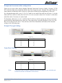
1
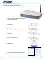
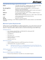
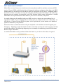
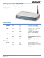
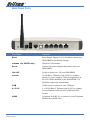
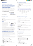
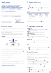
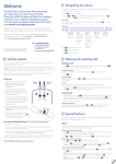
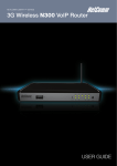
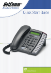
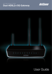
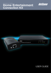
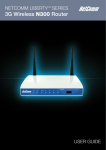
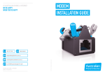
Contents
Overview ............................................................................................................ 3
NB8/NB8W Package Contents ........................................................................... 4
Selected terminology used in this manual .......................................................... 5
Minimum System Requirements: ...................................................................... 5
Do I need a micro filter? .................................................................................. 6
Getting to Know the NB8/NB8W ............................................................................ 7
LED Indicators ............................................................................................... 7
Default Settings ............................................................................................. 9
Restore Factory Default Setting ...................................................................... 10
Connecting the NB8/NB8W ................................................................................ 11
1. Connecting the Cables ............................................................................... 12
2. Establishing an ADSL connection via PPPoE................................................... 16
3. Establishing your Wireless Connection (for NB8W only) .................................. 17
Computer Hardware Configuration ....................................................................... 18
Windows® XP PCs ........................................................................................ 18
Windows 2000 PCs ....................................................................................... 18
Windows Me PCs .......................................................................................... 18
Appendix A: Cable Information ............................................................................ 20
Appendix B: Registration and Warranty Information ............................................... 22
2
YML804 Rev1
NB8/NB8W ADSL2+ Modem Router
Overview
Thank you for purchasing the NetComm NB8/NB8W ADSL2+ Modem Router. NetComm is proud
to introduce this entirely new class of all-in-one device incorporating ADSL2+ and Wireless in a
single compact unit. The NB8/NB8W is truly a ‘broadband communications gateway’ that, when
attached to the appropriate ISP services, will enable multiple broadband communications streams
to run concurrently into your home or office. Wireless and ethernet data services can be delivered
and distributed to multiple PCs at the same time, while the gateway can be managed via ‘Quality of
Service’ (QoS) controls to ensure that priority is given to the traffic of your choice.
Let’s look at some of the capabilities offered by the NB8/NB8W in brief:
ADSL Broadband
The NB8/NB8W offers the next generation of
broadband ADSL technology with ADSL2/2+, which
boosts ADSL’s performance significantly, improves
interoperability, and supports new applications,
services and deployment conditions.
Wireless (NB8W only)
In addition to fast, standard 802.11g-based wireless,
the NB8W incorporates Broadcom’s state-of-theart XPress and Afterburner technology to radically
improve the performance of wirelessly-connected
devices.
QoS
With the addition of bandwidth-hungry applications
to the SOHO/Home network the NB8/NB8W has
not overlooked one of the most important features
for a home Internet gateway – Quality of Service
(QoS) The QoS implementation in the NB8/NB8W
is extremely sophisticated allowing you to prioritise
data on your network according to rules you make.
NB8/NB8W ADSL2+ Modem Router
YML804 Rev1
3
NB8/NB8W Package Contents
Your NB8/NB8W contains the following items:
•
NB8 OR NB8W Broadband Communications
Gateway (NB8W shown)
•
Power Supply
•
RJ11 ADSL Line Connection Cable
•
USB Cable
•
RJ45 Cat 5 Ethernet cable
•
Installation CD
•
Package Contents List and Quick Start Guide
4
YML804 Rev1
NB8/NB8W ADSL2+ Modem Router
Selected terminology used in this manual
A telephone line used for a standard phone-line and service will be
referred to as POTS (=Plain Old Telephone Service)
Pass-through Line
The line that connects the NB8/NB8W to a POTS line may be
referred to as a pass-through line
RJ11
Telephone cables may be referred to as RJ11 which is the format of
the connection plug used for telephones
Ethernet
Local area network traffic will be carried by standard Category 5
cable referred to as Ethernet
RJ45
Ethernet cables may also be referred to as ‘RJ45’ which is the format
of the connection plug used for network devices
LAN
Local Area Network
WLAN
Wireless Local Area Network
For further terminology, see the Glossary Appendix in the User Guide included on the NB8/NB8W
CD-ROM.
POTS
Minimum System Requirements:
Different aspects of the NB8/NB8W have different requirements, so let’s look at them in turn. We’ll
start with your computer, which ought to match the following requirements if you are to enjoy the
benefits of a high-speed ADSL connection and use of Wireless Networking (for the NB8W only).
PC Requirements:
•
Any computer running Windows 98/2000/Me/XP or Macintosh OSX
•
Ethernet or Wireless Network card
•
CD-ROM drive
•
Web browser e.g.
•
Internet Explorer 5.1 (or better)
•
Netscape Navigator
•
Mozilla FireFox 1.0.4
ADSL Requirement:
•
ADSL broadband connection to an ISP (Internet Service Provider)
•
ADSL Splitter/Filter (see below for details)
Note:
Connection at ADSL2 or 2+ rate depends on the service offered by your
ISP; the device will operate at standard ADSL rates in the absence of the
2 or 2+ service. Consult your ISP for details.
USB Requirements:
•
USB Port
Wireless Requirements (for NB8W only):
•
Wireless Network Interface Card (NIC) for each intended computer
NB8/NB8W ADSL2+ Modem Router
YML804 Rev1
5
Do I need a micro filter?
Micro filters are used to prevent interference between phones and fax machines, and your ADSL
service. If your ADSL-enabled phone line is being used with any equipment other than your ADSL
Modem then you will need to use one Micro filter for each phone device in use. Telephones and/or
facsimiles in other rooms that are using the same line will also require Microfilters. The following
diagram gives an example of connecting your ADSL Modem/ Router using a Microfilter. A suitable
Microfilter can be purchased from NetComm or your Service Provider, if required.
A central splitter may be installed with your ADSL service or when your current phone line is
upgraded to ADSL. If your telephone line is already split you will not need to use a Microfilter on
each device.- Check with your ADSL or phone service provider if you are unsure as to whether a
splitter is installed at your premises.
Each micro filter is connected in-line with your telephone or fax machine so that all signals pass
through it. Telephones and/or facsimiles in other rooms that are using the same extension will also
require Microfilters. The following diagram gives an example of connecting your ADSL Modem/
Router using a Microfilter.
A suitable Microfilter can be purchased from NetComm or your Service Provider, if required.
6
YML804 Rev1
NB8/NB8W ADSL2+ Modem Router
Getting to Know the NB8/NB8W
It is recommended that you take a moment to acquaint yourself with
the indicator lights, ports and default settings of the
NB8/NB8W prior to commencing
with installation.
LED Indicators
LED
Colour
Mode
Function
POWER
Green
ADSL
Green
On
Off
On
Off
The router is powered up
The router is powered down
The ADSL Link is established
The ADSL Link is not
established
The ADSL line is training or
traffic is passing through
Ethernet link is established
Ethernet link is not established
Data transmitting/receiving over
Ethernet
Data transmitting/receiving over
USB
Green
Blink
LAN 1x ~4x Green
Green
On
Off
Blink
Green
Blink
Green
On
Wireless module is ready
Off
Wireless module is not installed
Blink
Data transmitting/receiving over
Wireless
USB
NB8W only
WLAN
Green
NB8/NB8W ADSL2+ Modem Router
YML804 Rev1
7
Back Panel Ports
Port Name
Function
Reset
Reset button. Depress for 10 seconds to return your
NB8/NB8W to its default settings.
Antenna (for NB8W only)
Wireless LAN antenna.
Power
Connect the power adaptor that comes with your
NB8/NB8W.
On / Off
Switch to power on / off your NB8/NB8W.
Console
10/100 Base-T Ethernet jack (RJ-45) to connect
directly to your computer. (Refer to Appendix A in
the User Guide included on the NB8/NB8W CDROM for connection information)
USB
USB1.0 port to connect to your USB port.
4 x LAN
4 x 10/100 Base-T Ethernet jack (RJ-45) to connect
to your Ethernet Network card or Ethernet Hub /
Switch.
ADSL
Telephone jack (RJ-11) to connect to your Telephone
Wall Socket (ADSL line).
8
YML804 Rev1
NB8/NB8W ADSL2+ Modem Router
Default Settings
The following are the default LAN (Local Area Network), WAN (Wide Area Network) and WLAN
(Wireless LAN) settings.
LAN (Management)
•
Static IP Address: 192.168.1.1;
•
Subnet Mask: 255.255.255.0;
•
Default Gateway: blank;
WAN (Internet)
•
Empty: Once you have run through ‘ADSL Quick Setup’ you will have a saved WAN
connection;
•
Default connection type: PPPoE (most common for Australian ISPs);
•
VPI / VCI: 8 / 35;
Modem Access
•
Username: admin
•
Password: admin
NB8/NB8W ADSL2+ Modem Router
YML804 Rev1
9
Restore Factory Default Setting
Restore Factory Defaults will reset the NB8/NB8W to its factory default configuration. Occasions
may present themselves where you need to restore the factory defaults on your NB8/NB8W such as:
•
You have lost your username and password and are unable to login to your NB8/
NB8W’s web configuration page;
•
You have purchased your NB8/NB8W from someone else and need to reconfigure the
device to work with your ISP;
•
You are asked to perform a factory reset by NetComm Support staff
In order to restore your NB8/NB8W to its factory default settings, please follow these steps:
•
Ensure that your NB8/NB8W is powered on (for at least 10 seconds);
•
Use a paper clip or a pencil tip to depress the reset button for ten seconds and release. At
this point, the reset is in progress. Do not power off the unit at this point;
•
When indicator lights return to steady green, reset is complete. The default settings are
now restored. The entire process takes about 45 seconds to complete;
•
Once you have reset your NB8/NB8W to its default settings you will be able to access
the device’s configuration web interface using http://192.168.1.1 with username ‘admin’
and password ‘admin’;
10
YML804 Rev1
NB8/NB8W ADSL2+ Modem Router
Connecting the NB8/NB8W
The diagram below shows you how to connect the NB8/NB8W to your PC, ADSL and POTS
service.
The initial set-up is required to get the NB8/NBW up and running:
1. Connecting the cables between NB8/NB8W, PC and telephone(s) and power on
2. Establish ADSL connection
3. Set up Wireless (for NB8W only)
NB8/NB8W ADSL2+ Modem Router
YML804 Rev1
11
1. Connecting the Cables
Note:
If you wish to link to the NB8W wirelessly at the outset, see 3.
Establishing a Wireless Connection below.
If you wish to connect the Console port, refer to Appendix A in the User
Guide included on the NB8/NB8W CD-ROM.
The NB8/NB8W can be connected via a USB cable or an Ethernet cable or both. The USB
connection is simply an ethernet simulation. As far as your computer is concerned the USB
connection is an Ethernet connection, hence DHCP and other protocols will work the same as for
Ethernet. To connect to your ADSL Router, you need to have either an Ethernet Port or a USB Port
present on your Computer/Notebook.
Connecting your NB8/NB8W ADSL Modem via ETHERNET
1. Connect your NB8/NB8W to either a computer directly or a network hub or switch
using CAT5 ethernet cables.
2. Connect the power pack to the ADSL Modem and switch on the power switch.
3. Ensure that there is a LAN link light on the NB8/NB8W.
4. Ensure that the computer you intend to use has an IP address in the same subnet as the
NB8/NB8W ADSL Modem. (e.g. the NB8/NB8W’s default IP is 192.168.1.1 - your
computer should be on 192.168.1.100 or similar.) If you have DHCP enabled on your
computer, the NB8/NB8W will assign your computer a suitable IP address.
5. Ensure that your computer has a LAN link light.
6. Connect one end of the ADSL phone line to the NB8/NB8W ADSL Modem and the
other end to the wall socket.
12
YML804 Rev1
NB8/NB8W ADSL2+ Modem Router
Connecting your NB8/NB8W ADSL Modem via USB
1. Connect the power pack to the NB8/NB8W ADSL Modem and switch on the power
switch.
2. Connect your NB8/NB8W to a computer directly via USB cable.
3. When the computer is booted, the Add New Hardware Wizard will launch and prompt
you to provide a driver for your NB8/NB8W ADSL Modem. Insert the CD provided.
4. Follow the on-screen prompts to load the driver. Refer to the section below for more
detailed information. (You may need to restart your computer).
5. Connect one end of the ADSL phone line to the NB8/NB8W ADSL Modem and the
other end to the wall socket.
Installing the USB driver (Windows 98/Me/2000/XP only)
When you install the USB driver on your computer it creates a Virtual Ethernet Adapter,
which can be configured in the same way as a Network Interface card with DHCP or static
IP address. To install the USB driver please follow the steps below:
1.
2.
3.
4.
Boot your machine into Windows 98/Me/2000/XP.
Insert your NetComm NB8/NB8W CD into your CD-ROM drive.
Plug power up to your NB8/NB8W and switch ON.
Plug a USB cable from the back of the unit into a spare USB socket on your computer.
NB8/NB8W ADSL2+ Modem Router
YML804 Rev1
13
5. The Windows “Add New Hardware Wizard” should appear and will ask “Can Windows
connect to Windows Update to search for software?” Ensure the “No, not this time”
option is selected and click Next to continue.
6. Ensure the option “Install from a list or specific location [Advanced]” is chosen and
click Next.
7. Choose “Search for the driver in these locations” and “Search removable media (floppy,
CD-ROM...)”. Untick any other boxes and click on the Browse button. Open the CDROM drive location of your NetComm NB8/NB8W CD and then select the ‘USBdriver’
folder.
14
YML804 Rev1
NB8/NB8W ADSL2+ Modem Router
8. You may be advised that the software has not passed Windows Logo testing. Click
“Continue Anyway” to proceed with the installation.
9. The USB driver will be installed. Click “Finish” to close the Wizard.
The next section explains how to establish your ADSL connection to the Internet.
Connecting your NB8/NB8W ADSL Modem via the Console Port for Management
The NB8/NB8W’s is equiped with a console port which can be used to configure the modem
and diagnose system issued. To access the NB8/NB8W interface using the console port a PC
must be equipped with an RS232 port and have a standard VT-100 emulation program such as
HyperTerminal 5 or Telix installed. Refer to Appendix A for detailed steps explaining how to
establish a console session.
NB8/NB8W ADSL2+ Modem Router
YML804 Rev1
15
2. Establishing an ADSL connection via PPPoE
Having physically connected your NB8/NB8W, the next step is to establish your ADSL connection
to the Internet, via your ISP.
Nearly all Australian ISPs connect their clients via a standard method called PPPoE (Point-to-Point
Protocol over Ethernet). Your NB8/NB8W has a ‘Quick Setup’ page configured for easy access via
PPPoE, so all you need do is enter the Username and Password issued by your ISP, click the ‘Save
& Connect’ button and connection will follow. This sequence will be explained here.
Note:
If you are not using a PPPoE connection type, then consult the section
under Advanced>WAN for details of choosing another connection type
(e.g. PPPoA, Static, Bridge, etc.). If unsure, follow the steps in this
section first.
At this point you must have your NB8/NB8W connected according to Section 1, above, with your
PC connected to the NB8/NB8W via Ethernet cable (or wireless link for NB8W only). You must
also have your ISP-supplied username and password on hand.
1. For Windows users, insert the accompanying CD into your CD-ROM drive. An autorun
screen should appear. Click the ‘Configure NB8/NB8W’ button;
Note:
If you do not have a CD-ROM or are running a non-Windows OS, you
can access the NB8/NB8W Configuration page by opening a web
browser and entering http://192.168.1.1 into the Address / Location field.
If you are not able to access the login screen by this means, go to the
section titled ‘Computer Hardware Configuration’ for instructions and
come back here when this is completed. Otherwise, proceed to next.
2. Enter the username ‘admin’ and password ‘admin’ and click ‘OK’;
3. The following web page is displayed:
4. Enter your PPPoE User ID and PPPoE Password and click the “Save & Reboot” button.
Do not adjust the VPI or VCI fields unless your ISP has instructed you to do so. The
NB8/NB8W will apply all of the settings in approximately 2 minutes.
16
YML804 Rev1
NB8/NB8W ADSL2+ Modem Router
5. After trying to connect the Basic > Home screen appears:
3. Establishing your Wireless Connection (for NB8W only)
Wireless networking provides an alternative connection to using Ethernet cable. Wireless access is
enabled by default on your NB8W with the following default settings:
•
Wireless network name (SSID):
•
Security: WEP (64-bit) HEX key: ‘a1b2c3d4e5’;
Note:
‘wireless’;
For advanced wireless settings of your NB8W refer to the section entitled
“Advanced Settings” in the User Guide included on the NB8/NB8W CDROM.
If you have a wireless Ethernet card on your PC, you can connect to your NB8W by following these
steps:
1. Connect the NB8W as in the diagram above, except for Point 1;
2. Enable the wireless connectivity of your PC;
3. Search for available wireless networks;
4. The default name (SSID) of the NB8W’s wireless network, ‘wireless’, will appear;
5. Connect to the SSID ‘wireless’ and when prompted, enter the default HEX password
which is A1B2C3D4E5;
6. Proceed with ‘Establishing an ADSL link via PPPoE’ above.
NB8/NB8W ADSL2+ Modem Router
YML804 Rev1
17
Computer Hardware Configuration
This section provides instructions for configuring the TCP/IP (Network) settings on your computer
to work with your Modem. These steps are only required if you are having trouble accessing your
Modem.
Windows® XP PCs
In the Windows task bar, click the Start button, and then click Control Panel.
Click on Network & Internet Connections icon. (Category mode only).
Click the Network Connections icon.
In the LAN or High-Speed Internet window, right-click on the icon corresponding to
your network interface card (NIC) and select Properties. (Often, this icon is labelled
Local Area Connection).
5. The Local Area Connection dialog box displays with a list of currently installed network
items. Ensure that the check box to the left of the item labelled Internet Protocol (TCP/
IP) is checked. Select Internet Protocol TCP/IP and click on Properties.
6. In the Internet Protocol (TCP/IP) Properties dialog box, click the radio button labelled
Obtain an IP address automatically. Also click the radio button labelled Obtain DNS
server address automatically.
7. Click OK twice to confirm your changes, and close the Control Panel.
1.
2.
3.
4.
Windows 2000 PCs
First, check for the IP protocol and, if necessary, install it:
1. In the Windows task bar, click the Start button, point to Settings, and then click
Control Panel.
2. Double-click the Network and Dial-up Connections icon.
3. In the Network and Dial-up Connections window, right-click the Local Area
Connection icon, and then select Properties.
4. In the Local Area Connection Properties dialog box, select Internet Protocol (TCP/IP),
and then click Properties
5. In the Internet Protocol (TCP/IP) Properties dialog box, click the radio button
labelled Obtain an IP address automatically. Also click the radio button labelled Obtain
DNS server address automatically.
6. Click OK twice to confirm and save your changes, and then close the Control Panel.
Windows Me PCs
1. In the Windows task bar, click the Start button, point to Settings, and then click
Control Panel.
2. Click on View All Control Panel Options.
3. Double-click the Network icon.
4. The Network Properties dialog box displays with a list of currently installed network
components. If the list includes Internet Protocol (TCP/IP), then the protocol has already
been enabled. Skip to step 10.
5. If Internet Protocol (TCP/IP) does not display as an installed component, click Add…
6. In the Select Network Component Type dialog box, select Protocol, and then click
Add…
18
YML804 Rev1
NB8/NB8W ADSL2+ Modem Router
7. Select Microsoft in the Manufacturers box.
8. Select Internet Protocol (TCP/IP) in the Network Protocols list, and then click OK.
You may be prompted to install files from your Windows ME installation CD or other
media. Follow the instructions to install the files. If prompted, click OK to restart your
computer with the new settings.
Next, configure the PC to accept IP information assigned by the modem:
9. Follow steps 1 – 4 above..
10. In the Network Properties dialog box, select TCP/IP, and then click Properties.
If you have multiple TCP/IP listings, select the listing associated with your network card
or adapter.
11. In the TCP/IP Settings dialog box, click the radio button labelled Obtain an IP address
automatically.
12. Click OK twice to confirm and save your changes, and then close the Control Panel.
Windows 95, 98 PCs
First, check for the IP protocol and, if necessary, install it:
1. In the Windows task bar, click the Start button, point to Settings, and then click
Control Panel.
2. Double-click the Network icon.
3. The Network dialog box displays with a list of currently installed network components.
If the list includes TCP/IP, and then the protocol has already been enabled. Skip to step
9.
4. If TCP/IP does not display as an installed component, click Add… The Select Network
Component Type dialog box displays.
5. Select Protocol, and then click Add… The Select Network Protocol dialog box
displays.
6. Click on Microsoft in the Manufacturers list box, and then click TCP/IP in the
Network Protocols list box.
7. Click OK to return to the Network dialog box, and then click OK again. You may
be prompted to install files from your Windows 95/98 installation CD. Follow the
instructions to install the files.
8. Click OK to restart the PC and complete the TCP/IP installation.
Next, configure the PCs to accept IP information assigned by the Modem:
9. Follow steps 1 – 3 above.
10. Select the network component labelled TCP/IP, and then click Properties. If you have
multiple TCP/IP listings, select the listing associated with your network card or adapter.
11. In the TCP/IP Properties dialog box, click the IP Address tab.
12. Click the radio button labelled Obtain an IP address automatically.
13. Click OK twice to confirm and save your changes. You will be prompted to restart
Windows.
14. Click Yes.
Note:
For detailed information regarding the advanced features of this product,
refer to the Advanced Settings sections in the User Guide included on
the NB8/NB8W CD-ROM.
NB8/NB8W ADSL2+ Modem Router
YML804 Rev1
19
Appendix A: Cable Information
This cable information is provided for your reference only. Please ensure you only connect the
appropriate cable into the correct socket on either this product or your computer.
If you are unsure about which cable to use or which socket to connect it to, please refer to the
hardware installation section in this manual. If you are still not sure about cable connections, please
contact a professional computer technician or NetComm for further advice.
RJ-45 Network Ports
RJ-45 Network Ports can connect any networking devices that use a standard LAN interface, such as
a Hub/Switch Hub or Router. Use unshielded twisted-pair (UTP) or shield twisted-pair (STP) cable
to connect the networking device to the RJ-45 Ethernet port. Depending on the type of connection,
10Mbps or 100Mbps, use the following Ethernet cable, as prescribed.
10Mbps:
Use EIA/TIA-568-100-Category 3, 4 or 5 cable.
100Mbps:
Use EIA/TIA-568-100-Category 5 cable.
Note:
To prevent loss of signal, make sure that the length of any twisted-pair
connection does not exceed 100 metres.
RJ-45 Connector
Pin Assignment
1
2
3
6
4,5,7,8
Normal Assignment
Input Receive Data +
Input Receive Data Output Transmit Data +
Output Transmit Data Not used
Figure 1
RJ-45 plug
attached to cable
Figure 2
20
YML804 Rev1
NB8/NB8W ADSL2+ Modem Router
Straight and crossover cable configuration
There are two types of the wiring: Straight-Through Cables and Crossover Cables. Category 5 UTP/
STP cable has eight wires inside the sheath. The wires form four pairs. Straight-Through Cables has
same pinouts at both ends while Crossover Cables has a different pin arrangement at each end.
In a straight-through cable, wires 1,2,3,4,5,6,7 and 8 at one end of the cable are still wires 1~8 at the
other end. In a crossover cable, the wires of 1,2,3,6 are reversed so that wire 1 become 3 at the other
end of the cable, 2 becomes 6, and so forth.
To determine which wire is wire 1, hold the RJ-45 cable tip with the spring clip facing towards the
ground and the end pointing away from you. The copper wires exposed upwards to your view. The
first wire on the far left is wire 1. You can also refer to the illustrations and charts of the internal
wiring on the following page.
Straight-Through Cabling
Figure 3
Wire
1
2
3
6
Becomes
1
2
3
6
Cross-Over Cabling
Figure 4
Wire
1
2
3
6
Note:
Becomes
3
6
1
2
To prevent loss of signal, make sure that the length of any twisted-pair
connection does not exceed 100 metres.
NB8/NB8W ADSL2+ Modem Router
YML804 Rev1
21
Appendix B: Registration and Warranty Information
All NetComm Limited (“NetComm”) products have a standard 12 month warranty from date of purchase against
defects in manufacturing and that the products will operate in accordance with the specifications outlined in the User
Guide. However some products have an extended warranty option (please refer to your packaging). To be eligible
for the extended warranty you must supply the requested warranty information to NetComm within 30 days of the
original purchase by registering on-line via the NetComm web site at:
www.netcomm.com.au
Contact Information
If you have any technical difficulties with your product, please do not hesitate to contact NetComm’s Customer
Support Department.
Email:
[email protected]
Fax:
(+612) 9424-2010
Web:
www.netcomm.com.au
Copyright Information
This manual is copyright. Apart from any fair dealing for the purposes of private study, research, criticism or review,
as permitted under the Copyright Act, no part may be reproduced, stored in a retrieval system or transmitted in any
form, by any means, be it electronic, mechanical, recording or otherwise, without the prior written permission of
NetComm Limited. NetComm Limited accepts no liability or responsibility, for consequences arising from the use of
this product. Please note that the images used in this document may vary slightly from those of the actual product.
Specifications are accurate at the time of the preparation of this document but are subject to change without notice.
NetComm Limited reserves the right to change the specifications and operating details of this product without notice.
NetComm is a registered trademark of NetComm Limited. All other trademarks are acknowledged the property of
their respective owners.
Customer Information
ACA (Australian Communications Authority) requires you to be aware of the following information and warnings:
(1) This unit shall be connected to the Telecommunication Network through a line cord which meets the
requirements of the ACA TS008 Standard.
(2) This equipment has been tested and found to comply with the Standards for C-Tick and or A-Tick as set
by the ACA. These standards are designed to provide reasonable protection against harmful interference in a residential installation. This equipment generates, uses, and can radiate radio noise and,
if not installed and used in accordance with the instructions detailed within this manual, may cause
interference to radio communications. However, there is no guarantee that interference will not occur
with the installation of this product in your home or office. If this equipment does cause some degree of
interference to radio or television reception, which can be determined by turning the equipment off and
on, we encourage the user to try to correct the interference by one or more of the following measures:
• Change the direction or relocate the receiving antenna.
• Increase the separation between this equipment and the receiver.
• Connect the equipment to an alternate power outlet on a different power circuit from that to which
the receiver/TV is connected.
• Consult an experienced radio/TV technician for help.
(3) The power supply that is provided with this unit is only intended for use with this product. Do not use
this power supply with any other product or do not use any other power supply that is not approved for
use with this product by NetComm. Failure to do so may cause damage to this product, fire or result in
personal injury.
22
YML804 Rev1
NB8/NB8W ADSL2+ Modem Router
Product Warranty
The warranty is granted on the following conditions:
1. This warranty extends to the original purchaser (you) and is not transferable;
2. This warranty shall not apply to software programs, batteries, power supplies, cables or other accessories supplied in or with the product;
3. The customer complies with all of the terms of any relevant agreement with NetComm and any other
reasonable requirements of NetComm including producing such evidence of purchase as NetComm
may require;
4. The cost of transporting product to and from NetComm’s nominated premises is your responsibility;
and,
5. NetComm does not have any liability or responsibility under this warranty where any cost, loss, injury
or damage of any kind, whether direct, indirect, consequential, incidental or otherwise arises out of
events beyond NetComm’s reasonable control. This includes but is not limited to: acts of God, war, riot,
embargoes, acts of civil or military authorities, fire, floods, electricity outages, lightning, power surges,
or shortages of materials or labour.
6. The customer is responsible for the security of their computer and network at all times. Security features may be disabled within the factory default settings. NetComm recommends that you enable these
features to enhance your security.
The warranty is automatically voided if:
1. You, or someone else, use the product, or attempts to use it, other than as specified by NetComm;
2. The fault or defect in your product is the result of a voltage surge subjected to the product either by
the way of power supply or communication line, whether caused by thunderstorm activity or any other
cause(s);
3. The fault is the result of accidental damage or damage in transit, including but not limited to liquid spillage;
4. Your product has been used for any purposes other than that for which it is sold, or in any way other
than in strict accordance with the user manual supplied;
5. Your product has been repaired or modified or attempted to be repaired or modified, other than by a
qualified person at a service centre authorised by NetComm; and,
6. The serial number has been defaced or altered in any way or if the serial number plate has been
removed.
Limitations of Warranty
The Trade Practices Act 1974 and corresponding State and Territory Fair Trading Acts or legalisation of another
Government (“the relevant acts”) in certain circumstances imply mandatory conditions and warranties which cannot
be excluded. This warranty is in addition to and not in replacement for such conditions and warranties.
To the extent permitted by the Relevant Acts, in relation to your product and any other materials provided with the
product (“the Goods”) the liability of NetComm under the Relevant Acts is limited at the option of NetComm to:
• Replacement of the Goods; or
• Repair of the Goods; or
• Payment of the cost of replacing the Goods; or
• Payment of the cost of having the Goods repaired.
NB8/NB8W ADSL2+ Modem Router
YML804 Rev1
23