1
Opti
3
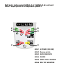
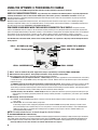
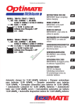
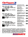
MODEL: TM430 / TM431 / TM432
AC: 100 – 240VAC
50-60Hz
0.23A @ 100Vac / 0.15A @ 240Vac
DC: 0.8A
12V
1 x 12V
+
- STD / AGM-MF / GEL / CYCLIC CELL
2.5 - 50Ah
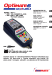
MODEL: TM450 / TM451 / 452
AC: 100 – 240VAC
50-60Hz
0.46A @ 100Vac / 0.30A @ 240Vac
DC: 2 x 0.8A
12V (independent)
2 x 12V
+
- STD / AGM-MF / GEL / CYCLIC CELL
2.5 - 50Ah
MODEL: TM454 / TM455 / 456
AC: 100 – 240VAC
50-60Hz
0.92A @ 100Vac / 0.60A @ 240Vac
DC: 4 x 0.8A
12V (independent)
4 x 12V
+
- STD / AGM-MF / GEL / CYCLIC CELL
2.5 - 50Ah
INSTRUCTIONS FOR USE
IMPORTANT: Read completely
before charging
MODE D’EMPLOI
IMPORTANT: à lire avant
d’utiliser l’appareil
MODO DE EMPLEO
IMPORTANTE: a leer antes de
utilizar el aparato
INSTRUÇÕES DE UTILIZAÇÃO
IMPORTANTE: Ler antes de
utilizar.
ANWENDUNGSVORSCHRIFTEN
WICHTIG: Vollständig vor der
Benutzung lesen
GEBRUIKSAANWIJZING
BELANGRIJK: Lees volledig
voor gebruik
ISTRUZIONI PER L’USO
IMPORTANTE: da leggere prima
di utilizzare l’apparecchio
INSTRUKTIONER
VIKTIGT: läs följande
fullständiga instruktioner
för användningen innan du
använder laddaren
"VUPNBUJDDIBSHFSGPS7MFBEBDJECBUUFSJFTt$IBSHFVSBVUPNBUJRVFQPVS
CBUUFSJFT 7 QMPNCBDJEF t $BSHBEPS BVUPNÈUJDP QBSB CBUFSÓBT 7
QMPNPÈDJEPt$BSSFHBEPSBVUPNÈUJDPQBSBCBUFSJBTEF7DIVNCPÈDJEPt
"VUPNBUJTDIF-BEFHFSÊUGàS7#MFJ4ÊVSF#BUUFSJFOt"VUPNBUJTDIFMBEFS
WPPS 7 MPPE[VVS BDDVT t $BSJDBCBUUFSJF BVUPNBUJDP QFS CBUUFSJF 7
QJPNCPBDJEPt"VUPNBUJTLEJBHOPTUJTLMBEEBSFGÚS7CMZCBUUFSJFS
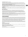
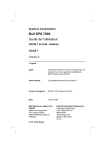
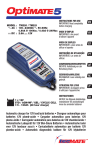
Multi bank / station models OptiMate 3 x2 OptiMate 3 x4: FBDICBOL
TUBUJPOPVUQVUPQFSBUFTBTBOJOEFQFOEFOU0QUJ.BUF
#1
#5
#2
#6
#3
#4
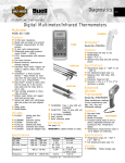
LED #1 - AC POWER (100-240V)
LED #2 - Reverse polarity
LED #3 - SAVE/DESULPHATE
LED #4 - CHARGE
LED #5 - GREEN: TEST & MAINTAIN
LED #6 - RED: TEST & MAINTAIN
3
THIS PORTION OF THE MANUAL CONTAINS IMPORTANT SAFETY INSTRUCTIONS
FOR THE OPTIMATE 3 BATTERY CHARGER. IT IS OF THE UTMOST IMPORTANCE
THAT EACH TIME, BEFORE USING THE CHARGER, YOU READ AND EXACTLY
FOLLOW THESE INSTRUCTIONS. SAVE THESE INSTRUCTIONS.
"650."5*$$)"3(&3'037-&"%"$*%#"55&3*&4
DO NOT USE FOR NiCd, NiMH, Li-Ion OR NON-RECHARGEABLE BATTERIES.
1. CAUTION : CLASS II APPLIANCE. DO NOT CONNECT TO GROUND.
2. For indoor use only. Do not expose charger to rain or snow.
3. Use of an attachment not recommended or sold by the battery charger manufacturer may result in a risk of fire, electric shock,or
injury to persons.
4. To reduce risk of damage to electric plug and cord,pull by plug rather than cord when disconnecting charger.
5. An extension cord should not be used unless absolutely necessary. Use of improper extension cord could result in a risk of fire and
electric shock.If extension cord must be used make sure that :
a) pins on plug of extension cord are the same number, size and shape as those of plug on charger.
b) the extension cord is property wired and in good electrical condition,and
c) the conductor wire size is large enough for the AC ampere rating of the charger as specified in the table below.
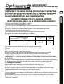
AC INPUT RATING IN AMPERES
Equal to or greater than
But less than
2A
3A
LENGTH OF CORD, FEET
(m)
AWG SIZE OF
CORD
25 (17.6)
50 (15.2)
100 (30.5)
18
18
14
6. Do not operate charger with damaged cord or plug - replace the cord or plug immediately.
7. Do not operate charger if it has received a sharp blow, been dropped,or otherwise damaged in any way; take it to a qualified
serviceman.
8. Do not disassemble charger; take it to a qualified serviceman when service or repair is required.
Incorrect reassembly may result in a risk of electric shock or fire.
9. To reduce risk of electric shock, unplug the charger from outlet before attempting any maintenance or cleaning.
Turning off controls will not reduce this risk.Clean only with slightly moist,not wet, cloth.Do not use solvents.
10. WARNING - RISK OF EXPLOSIVE GASES.
a) WORKING IN VICINITY OF A LEAD-ACID BATTERY IS DANGEROUS. B ATTERIES GENERATE EXPLOSIVE GASES DURING NORMAL
BATTERY OPERATION. FOR THIS REASON, IT IS OF UTMOST IMPORTANCE THAT YOU FOLLOW THE INSTRUCTIONS EACH TIME YOU
USE THE CHARGER.
b) To reduce risk of battery explosion,follow these instructions and those published by the battery manufacturer and manufacturer of
any equipment you intend to use in vicinity of the battery. Review cautionary marking on these products and on engine.
1&340/"-13&$"65*0/4
a) Someone should be within range of your voice OR close enough to come to your aid when you work near a lead-acid battery.
b) Have plenty of fresh water and soap nearby in case battery acid contacts skin, clothing or eyes.
c) Wear complete eye protection and clothing protection. Avoid touching eyes while working near battery.
d) If battery acid contacts or enters eye, flood eye with cold running water for at least 10 minutes and get medical attention
immediately. If battery acid contacts skin or clothing, wash immediately with soap & water. If acid enters an eye , immediately flood
eye with running cold water for at least 10 minutes & get medical attention immediately.
e) NEVER smoke or allow a spark or flame in vicinity of battery or engine.
f) Be extra cautious to reduce risk of dropping a metal tool onto battery. It might spark or short-circuit battery or other electrical part
that may cause explosion.
g) Remove personal metal items such as rings, bracelets ,necklaces , and watches when working with a lead-acid battery. A
lead-acid battery can produce a short-circuit current high enough to weld a ring or the like to metal, causing a severe burn.
i) NEVER charge a frozen battery.
3
4"'&5:
Opti
*.1035"/54"'&5:
*/4536$5*0/4'03$"/"%"64"
13&1"3*/(50$)"3(&
4"'&5:64$"/
a) If necessary to remove battery from vehicle to charge,always remove grounded terminal from battery first.
Make sure all accessories in the vehicle are off, so as not to cause an arc.
b) Be sure area around battery is well ventilated while battery is being charged. Gas can be forcefully blown away by using a piece of
cardboard or other non-metallic material as a fan.
c) Clean battery terminals.Be careful to keep corrosion from coming in contact with eyes.
d) Add distilled water in each cell until battery acid reaches level specified by battery manufacturer. This helps purge excessive gas
from cells. Do not overfill. For a battery without cell caps, such as valve regulated lead acid (VRLA) or absorbed glass mat (AGM)
batteries, carefully follow manufacturer’s recharging instructions.
e) Study all battery manufacturer’s specific precautions such as removing or not removing cell caps while charging and
recommended rates of charge.
f) Determine voltage of battery by referring to vehicle or other user’s manual and BEFORE MAKING THE BATTERY CONNECTIONS,
MAKE SURE TH AT THE VOLTAGE OF THE BATTERY YOU ARE GOING TO CHARGE MATCHES THE OUTPUT VOLTAGE OF THE CHARGER.
13. CHARGER LOCATION.
a) Locate charger as far away from battery as DC cables permit.
b) Never place charger directly above batterv being charged; gases from battery will corrode and damage the charger. c) Never allow
battery acid to drip on charger when reading gravity or filling battery. Do not operate charger in a closed-in area or restrict ventilation
in any way.
d) Do not set a battery on top of charger. IMPORTANT : Place charger on a hard flat surface or mount onto a vertical surface. Do not
place on plastic, leather or textile surface.
%$$0//&$5*0/13&$"65*0/4
a) Connect and disconnect DC output clips only after setting any charger switches to off position and removing AC cord from electric
outlet. Never allow clips to touch each other, however should this happen no damage will result to the charger circuit & the automatic
charging programme will just reset to «start».
b) Attach clips to battery and chassis as indicated in 15(e), 15(f), and 16(b) through 16(d).
NOTE : This battery charger has an automatic safety feature that will prevent it from operating if the battery has been inversely
connected. Set charger switches to off position and/or remove AC cord from electrical outlet, disconnect the battery clips, then
reconnect correctly according to the instructions below.
'0--085)&4&45&148)&/#"55&3:*4*/45"--&%*/7&)*$-&"41"3,
/&"3"#"55&3:.":$"64&#"55&3:&91-04*0/503&%6$&3*4,0'"
41"3,/&"3#"55&3:
a) Position AC and DC cords so as to reduce risk of damage by hood, door or moving engine part.
b) Stay clear of fan -blades, belts,pulleys,and other parts that can cause injury to persons.
c) Check polarity of battery posts.POSITIVE (POS, P, +) battery post usually has larger diameter than NEGATIVE (NEG, N,–) post.
d) Determine which post of battery is grounded (connected) to the chassis. If negative post is grounded to chassis (as in most
vehicles),see (e). If positive post is grounded to the chassis,see (f).
e) For negative-grounded vehicle, connect POSITIVE (RED) clip from battery charger to POSITIVE (POS, P, + ) ungrounded post of
battery. Connect NEGATIVE (BLACK) clip to vehicle chassis or engine block away from battery. Do not connect clip to carburetor, fuel
lines, or sheet-metal body parts. Connect to a heavy gage metal part of the frame or engine block.
f) For positive-grounded vehicle, connect NEGATIVE (BLACK) clip from battery charger to NEGATIVE (NEG. N , -) ungrounded post of
battery. Connect POSITIVE (RED) clip to vehicle chassis or engine block away from battery. Do not connect clip to carburetor, fuel
lines, or sheet-metal body parts. Connect to a heavy gage metal part of the frame or engine block.
g) When disconnecting charger, turn switches to off, disconnect AC cord,remove clip from vehicle chassis,and then remove clip from
battery terminal.
h) See operating instructions for length of charge information.
'0--085)&4&45&148)&/#"55&3:*40654*%&7&)*$-&"41"3,/&"35)&#"55&3:.":$"64&#"55&3:&91-04*0/50
3&%6$&3*4,0'"41"3,/&"3#"55&3:
a) Check polarity of battery posts. POSITIVE (POS, P, +) battery post usually has a larger diameter than NEGATIVE (NEG,N, -) post.
b) This battery charger has an automatic safety feature that will prevent it from operating if the battery has been inversely connected.
The charger does allow charge current unless a voltage of at least 2V is sensed.
c) Connect POSITIVE (RED) charger clip to POSITIVE (POS, P, +) post of battery.
d) Connect NEGATIVE (BLACK) charger clip to NEGATIVE (NEG, N, -) battery post of the battery.
e) Do not face battery when making final connection.
f) When disconnecting charger, always do so in reverse sequence of connecting procedure & break first connection while as far away
from battery as practical.
g) A marine (boat) battery must be removed & charged on shore. To charge it on board requires equipment specially designed for
marine use.
4
Opti
3
4"'&5:
"650."5*$."*/5&/"/$&$)"3(&3'037-&"%"$*%#"55&3*&4
'30."h50"h"4'06/%*/
DO NOT USE FOR NiCd, NiMH, Li-Ion OR NON-RECHARGEABLE BATTERIES.
$IBSHFSBUF"IIPVSXJMMSFDIBSHFB"ICBUUFSZJOIPVST
*OQVU7 NBYJNVN"5IFNBYJNVNPVUQVUDVSSFOUJT"
IMPORTANT: READ THE FOLLOWING INSTRUCTIONS BEFORE USING THE CHARGER
5IJTBQQMJBODFJTOPUJOUFOEFEGPSVTFCZQFSTPOTJODMVEJOHDIJMESFO
XJUISFEVDFEQIZTJDBM
TFOTPSZPSNFOUBMDBQBCJMJUJFTPSMBDLPGFYQFSJFODFBOELOPXMFEHFVOMFTTUIFZIBWFCFFOHJWFO
TVQFSWJTJPOPSJOTUSVDUJPODPODFSOJOHVTFPGUIFBQQMJBODFCZBQFSTPOSFTQPOTJCMFGPSUIFJS
TBGFUZ$IJMESFOTIPVMECFTVQFSWJTFEUPFOTVSFUIBUUIFZEPOPUQMBZXJUIUIFBQQMJBODF
4"'&5:8"3/*/("/%/05&4#BUUFSJFTFNJU&91-04*7&("4&4QSFWFOUGMBNFPSTQBSLTOFBSCBUUFSJFTDisconnect AC
power supply before making or breaking DC/battery connections. Battery acid is highly corrosive. Wear protective clothing and eyewear and
avoid contact. In case of accidental contact, wash immediately with soap and water. Check that the battery posts are not loose; if so, have the
battery professionally assessed. If the battery posts are corroded, clean with a copper wire brush; if greasy or dirty clean with a rag damped in
detergent. Use the charger only if the input and output leads and connectors are in good, undamaged condition. If the input cable is damaged, it
is essential to have it replaced without delay by the manufacturer, his authorised service agent or a qualified workshop, to avoid danger. Protect
your charger from acid and acid fumes and from damp and humid conditions both during use and in storage. Damage resulting from corrosion,
oxidation or internal electrical short-circuiting is not covered by warranty. Distance the charger from the battery during charging to avoid
contamination by or exposure to acid or acidic vapours. If using it in the horizontal orientation, place the charger on a hard, flat surface, but NOT
on plastic, textile or leather. Use the fixing holes provided in the enclosure base to attach the charger to any convenient, sound vertical surface.
&910463&50-*26*%4This charger is designed to withstand exposure to liquids accidentally spilled or splashed onto the casing
from above, or to light rainfall. Prolonged exposure to falling rain is inadvisable and longer service life will be obtained by minimizing such
exposure. Failure of the charger due to oxidation resulting from the eventual penetration of liquid into the electronic components, connectors
or plugs, is not covered by warranty.
#"55&3:$0//&$5*0/4 2 interchangeable connection sets are available, supplied with the charger is a set of battery clips for
charging the battery off-vehicle, the other connection set comes with metal eyelet lugs for permanent connection to the battery posts, and
re-sealable weatherproof cap on the connector that connects to the charger output cable. This connection set allows easy and sure
connection of the charger to maintain the battery on-vehicle. The resealable weatherproof cap is designed to protect the connector from dirt
and damp whenever the charger is not attached. Consult a professional service agent for assistance in attaching the metal eyelets to the
battery posts. Secure the connector with weatherproof cap so that it cannot foul any moving part of the vehicle or the cable can be pinched
or damaged by sharp edges. The in-line fuse in the eyelets connection set protects the battery against such accidental shorting across
positive and negative conductors. Replace any burnt fuse only with a similar new fuse of 15A rating.
$0//&$5*/(5)&$)"3(&3505)&#"55&3:
Disconnect AC power supply before making or breaking DC / battery connections.
If charging a battery in the vehicle with the battery clips, before making connections, first check that the battery clips can be safely
and securely positioned clear from surrounding wiring, metal tubing or the chassis. Make connections in the following order: First
connect to the battery terminal not connected to the chassis (normally positive), then connect the other battery clip (normally negative)
to the chassis well away from the battery and fuel line. Always disconnect in reverse sequence.
When charging a battery out of the vehicle with the battery clips, place it in a well ventilated area. Connect the charger to the battery:
RED clamp to POSITIVE (POS, P or +) terminal and BLACK clamp to NEGATIVE (NEG, N or –) terminal. Make sure the connections are
firm and secure. Good contact is important.
*GUIFCBUUFSZJTEFFQMZEJTDIBSHFEBOEQPTTJCMZTVMQIBUFE
SFNPWFGSPNUIFWFIJDMFBOEJOTQFDUUIFCBUUFSZCFGPSF
DPOOFDUJOHUIFDIBSHFSGPSBSFDPWFSZBUUFNQU Visually check the battery for mechanical defects such as a bulging or cracked
casing, or signs of electrolyte leakage. If the battery has filler caps and the plates within the cells can be seen from the outside, examine
the battery carefully to try to determine if any cells seem different to the others (for example, with white matter between the plates,
plates touching). If mechanical defects are apparent do not attempt to charge the battery, have the battery professionally assessed.
*GUIFCBUUFSZJTOFX, before connecting the charger read the battery manufacturer’s safety and operational instructions carefully. If
applicable, carefully and exactly follow acid filling instructions.
5
64*/(5)&015*."5&130$&&%*/(50$)"3(&
'PSTBGFUZSFBTPOTUIF0QUJ.BUFPVUQVUXJMMPOMZBDUJWBUFJGBCBUUFSZSFUBJOJOHBUMFBTU7JTDPOOFDUFE
7&3:'-"5/&(-&$5&%#"55&3*&4 1BZQBSUJDVMBSMZDMPTFBUUFOUJPOUPUIFGPMMPXJOHXIJDIJTFTQFDJBMMZJNQPSUBOUGPS
SFMBUJWFMZTNBMMCBUUFSJFTTVDIBTUIPTFVTFEPONPUPSDZDMFTMBXOUSBDUPSTKFUTLJTTOPXNPCJMFTBOETJNJMBSA battery left
deep-discharged for an extended period may develop permanent damage in one or more cells. Such batteries may heat up excessively
during high current charging.
Monitor the battery temperature during the first hour, then hourly there-after. Check for unusual signs, such as bubbling or leaking
electrolyte, heightened activity in one cell compared to others, or hissing sounds. If at any time the battery is uncomfortably hot to touch or
you notice any unusual signs, DISCONNECT THE CHARGER IMMEDIATELY.
&$0108&34"7*/(.0%&8)&/5)&$)"3(&3*4$0//&$5&%50"$4611-: The power converter
switches to ECO mode when the charger is not connected to a battery resulting in a very low power draw of less than 0,5W, equivalent to
power consumption of 0,012 kWh per day. When a battery is connected to the charger power consumption depends on the current demand
of the battery and its connected vehicle / electronic circuitry. After the battery has been charged and the charger is in long term
maintenance charge mode (to keep the battery at 100% charge) the total power consumption is estimated to be 0,060 kWh or less per day.
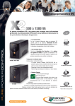
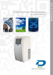
5IF-&%JOEJDBUPSTSFGFSSFEUPCFMPXBOEUIFDMBVTFTEFBMJOHXJUIUIFNBSFTFRVFODFEBTUIFZNBZDPNFPOUISPVHIUIFDPVSTF
PGUIFQSPHSBN
LED #1 - AC POWER (100-240V)
LED #2 - Reverse polarity
LED #3 - SAVE/DESULPHATE
LED #5 - GREEN: TEST & MAINTAIN
LED #6 - RED: TEST & MAINTAIN
LED #4 - CHARGE
-&%1PXFSPO$POGJSNT"$QPXFSTVQQMZUPUIFDIBSHFS-JHIUJOUFOTJUZJTMPXEVSJOH108&34"7*/(.0%&
-&%JOEJDBUFTJOWFSTFQPMBSJUZXSPOHPVUQVUDPOOFDUJPOT4XBQBSPVOEUPBDUJWBUFPVUQVU
LED #3 SAVE lights If the battery is extremely flat (deep-discharged or sulphated),
45"/%"3%SFDPWFSZGPSOFHMFDUFECBUUFSJFTLED #3 steady on : Up to 16V is applied with current limited to 0,2A. If the battery
is unable to accept a charge TURBO recovery will engage after 5 seconds. Batteries able to accept 0,2A of charge current will advance
to PULSE recovery.
563#0SFDPWFSZGPSWFSZCBEMZOFHMFDUFECBUUFSJFTSFNPWFEGSPNUIFWFIJDMFOutput voltage increases to a maximum of 20V
with current limited to 0,2A. The charger’s special recovery mode cannot engage if it senses that the battery is still connected to a
vehicle wiring circuit which effectively offers a lower electrical resistance than the battery on its own. However, if the deep-discharged
battery is not removed for recovery, neither battery nor vehicle electronics will be damaged.
16-4&SFDPWFSZGJOBMNJOVUFT LED #3 steady on: Current up to 0,8A is delivered in pulses to prepare the battery to accept
normal charge. This mode is particularly effective for recovery of factory activated / “hi-performance” pure lead or cyclic cell AGM
batteries.
-&%$IBSHFBOEDIBSHFWFSJGJDBUJPO
CHARGE: The BULK CHARGE stage delivers a constant current of about 0,8 Amps maximum into the battery, up to a voltage of
14,2 -14,5V.
VERIFICATION: The circuit verifies battery charge level.
If the battery requires further charging the programme reverts to BULK CHARGE for brief periods, delivering a variable current
pulse to the battery. These reversions may occur as many times as is necessary to reduce the battery’s current demand below
200mA at 13,6V (which is consistent with a battery that has accepted as much charge as its basic condition allows). (see
expected Charging time below.)
NOTE: For safety reasons there is an overall charge time limit of 48 hours.
70-5"(&3&5&/5*0/5&45-&%GMBTIJOH
%FMJWFSZof current to the battery is interrupted for 12 hours* to allow the program to determine the battery's ability to retain charge. For batteries
with a good state of health LED #5 (green) should continue to flash for the full 12 hours* period. Read the section NOTES ON TEST RESULTS on
reasons for poor test results or how to test a battery that returns a good result but cannot deliver sufficient power once it is returned to service.
* *GchargFEFMJWFSZXBTMFTTUIBOIPVSTUFTUFYUFOETVOUJMIPVSTIBTFMBQTFE
6
."*/5&/"/$&$)"3(&-&%TUFBEZPO
For 30 minutes the circuit offers current to the battery within a safe 13,6V voltage limit whilst the result of the voltage retention test is
displayed. If LED #6 (red) indicated the VOLTAGE RETENTION TEST will be repeated. A steady LED #5 (green) indicate the 30 minute float
charge maintenance periods follow and alternate wih the 30 minute REST (no charging) periods until the battery is disconnected. The battery
can draw current as required to support small loads and counter self-discharge.
.BJOUBJOJOHBCBUUFSZGPSFYUFOEFEQFSJPET The OptiMate will maintain a battery whos basic condition is good, for months
at a time. At least once every two weeks, check that the connections between the charger and battery are secure, and, in the case of
batteries with filler caps on each cell, disconnect the battery from the charger, check the level of the electrolyte and if necessary, top up the
cells XJUIEJTUJMMFEXBUFS/05BDJE
, then reconnect. When handling batteries or in their vicinity, always take care to observe the SAFETY
WARNINGS above.
$IBSHJOHUJNF The time required for the OptiMate 3 to complete a charge on a flat but otherwise undamaged battery is roughly equal
to the battery’s Ah rating, so a 10Ah battery should take no more than about 10 hours to progress to Step 4. Deep-discharged batteries may
take significantly longer.
/PUFTPO5&45SFTVMUT
1. If the red LED #6 lights a significant problem exists. The red LED means that after being charged the battery’s voltage is not being
sustained above 12,4V (roughly equal to 50% charge in a sealed AGM battery) or that despite recovery attempts the battery was
irrecoverable. This may be due to a defect in the battery itself, such as a short-circuited cell or total sulphation, or, in the case of a battery
still connected to the electrical system it supports, the red LED #6 may be signalling a loss of current through deteriorated wiring or a
degraded switch or contact, or in-circuit current-consuming accessories. A sudden load such as vehicle headlights being switched on while
the charger is connected can also cause the battery voltage to dip significantly.
2. GOOD TEST RESULT, but the battery cannot deliver sufficient power: Permanent damage within the battery may be causing excessive self
discharge (caused by the battery itself, even a partly damaged battery may initially retain sufficient power, but lose power faster than normal
there-after). Disconnect the battery from the OptiMate. After at least 12 hours reconnect and observe if SAVE LED #3 lights, indicating the
battery was unable to hold charge. If CHARGE LED #4 lights the battery retained at least 12,4V.
-*.*5&%8"33"/5:
TecMate (International) SA, Sint-Truidensesteenweg 252, B-3300 Tienen, Belgium, makes this limited warranty to the original purchaser at
retail of this product. This limited warranty is not transferable. TecMate (International) warrants this battery charger for three years from date
of purchase at retail against defective material or workmanship. If such should occur the unit will be repaired or replaced at the option of the
manufacturer. It is the obligation of the purchaser to forward the unit together with proof of purchase (see NOTE), transportation or mailing
costs prepaid, to the manufacturer or its authorized representative. This limited warranty is void if the product is misused, subjected to
careless handling, or repaired by anyone other than the factory or its authorized representative. The manufacturer makes no warranty other
than this limited warranty and expressly excludes any implied warranty including any warranty for consequential damages.
THIS IS THE ONLY EXPRESS LIMITED WARRANTY AND THE MANUFACTURER NEITHER ASSUMES NOR AUTHORIZES ANYONE TO ASSUME OR
MAKE ANY OTHER OBLIGATION TOWARDS THE PRODUCT OTHER THAN THIS EXPRESS LIMITED WARRANTY. YOUR STATUTORY RIGHTS ARE
NOT AFFECTED.
NOTE: Details at www.tecmate.com/warranty.
DPQZSJHIUª5FD.BUF*OUFSOBUJPOBM
OptiMate 3 and the names of other battery care products mentioned in these instructions such as BatteryMate, TestMate and TestMate mini,
are registered trademarks of TecMate International NV.
8"33"/5:JO$BOBEB64"$FOUSBM"NFSJDB4PVUI"NFSJDB
TecMate North America, Oakville, ON, Canada, as a wholy owned subsidiary of TecMate International, assumes the responsibility for product
warranty in these regions.
More information on TecMate products can be found at XXXUFDNBUFDPN.
7