1
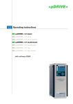
Altivar 68
Guide d'exploitation
User's manual
Coupleur de communication
Protocole Modbus
Communication coupler
Modbus protocol
VW3-A68303
Communication coupler Modbus protocol
Page 2
FRANÇAIS
Coupleur de communication protocole Modbus
Page 82
ENGLISH
Altivar 68
2
When the drive is powered up, the power components and some of the
control components are connected to the line supply. It is extremely
dangerous to touch them. The drive cover must be
closed.
ENGLISH
As a rule, the drive power supply must be disconne
before any operation on either the electrical or mechanical parts of the
installation or machine.
After the ALTIVAR has been switched off, wait for at least 1
minutes before working on the equipment
. This is the time
required for the capacitors to discharge. Check that the voltage between
the + and - terminals is lower than 60 V a.
The products and equipment described in this document may be changed
or modified at any time, either from a technical point of view or in the way
they are operated. Their description can in no way be considered
contractual.
This document is designed to be used in conjunction with the ATV-68
programming manual.
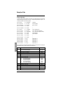
83
Hardware Installation _______________________________________________________________ 84
Presentation _______________________________________________________________ 84
Mounting the module on a DIN rail ______________________________________________ 85
Supplying the module with power _______________________________________________ 86
Connecting the module to the drive _____________________________________________ 87
Connecting the module to the Modbus network ____________________________________ 89
Example of connection _______________________________________________________ 90
Wiring recommendations _____________________________________________________ 91
Pin-outs __________________________________________________________________ 91
Configuring the communication functions _________________________________________ 92
Signalling ________________________________________________________________________ 95
Notation Conventions _______________________________________________________________ 96
Parameter Conversion to Physical Values _______________________________________________ 97
Modbus Protocol __________________________________________________________________ 98
RTU mode ________________________________________________________________ 98
Principle __________________________________________________________________ 98
Addresses _________________________________________________________________ 98
Modbus functions ___________________________________________________________ 99
Exception responses _______________________________________________________ 103
Calculating the CRC16 ______________________________________________________ 103
Module Modbus Data ______________________________________________________________ 104
Module Management ______________________________________________________________ 105
ATV68 Control and Monitoring _______________________________________________________ 106
ATV68 Control ___________________________________________________________________ 110
ATV68 Monitoring ________________________________________________________________ 116
Description of the ETA status word ____________________________________________ 116
Managing Communication Errors _____________________________________________________ 121
PKW Parameter-Setting Service _____________________________________________________ 122
ATV68 Configuration ______________________________________________________________ 128
Key to tables ______________________________________________________________ 128
B6. Serial Port configuration __________________________________________________ 128
D3. Configuration of analogue outputs __________________________________________ 134
D4. Configuration of logic outputs _____________________________________________ 135
ATV68 Diagnostics ________________________________________________________________ 136
A4. Display reference values _________________________________________________ 139
Example of Use __________________________________________________________________ 141
List of Parameters ________________________________________________________________ 145
84
ENGLISH
Contents
Hardware Installation
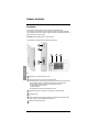
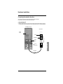
Presentation
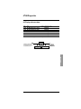
This module acts as an interface between the drive terminal port and the Modbus network.
Only one ATV68 can be connected to the module; the terminal port protocol is point-to-point (and RS232).
The term gateway is used in other documents. The gateway is designed to interconnect two networks. A
gateway can perform the function of a module.
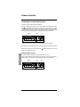
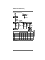
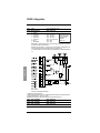
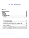
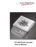
VW3-A68303 includes the Modbus module for ATV68 shown below.
The cables and other connection accessories should be ordered separately.
4
5
1
2
3
6
ENGLISH
Modbus
RTU
Configuration
ATV68
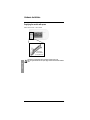
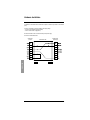
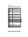
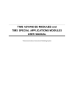
Key:
1
Module power supply plug-in connector (24V ±10%).
2
Female RJ45 connector for PC link and ABC Configurator software.
The Modbus module for ATV68 is factory-preset to operate in a standard mode, which don’t request
the ABC Configurator software. This manual describes the functions in this standard mode.
The ABC Configurator software is included in the PowerSuite offer. It allows to:
• modify the factory-preset of the module,
• diagnose the module.
The configurator has an online help which describes how to use it.
3
Female RJ45 connector for ATV68 link. Only one ATV68 can be connected to this port.
4
Six diagnostic LEDs.
5
Cover concealing the module configuration switches (see Configuring the communication functions
section, page 93). The LED descriptive label is attached to this.
6
Modbus 9-pin female SUB-D connector.
85
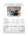
Hardware Installation
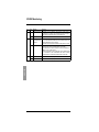
Mounting the module on a DIN rail
Mounting the module
Removing the module
1
2
Start by placing the module rear base on the top of
the rail, pushing downwards (1) to compress the
module spring. Then push the module against the
DIN rail (2) until the base of the module casing clips
onto the rail.
1
2
Start by pushing the module downwards (1) to
compress the module spring. Then pull the bottom
of the module casing forwards (2) until the back of
the casing unclips from the rail.
ENGLISH
Note: The spring also performs the function of earthing the module (Protective Earth).
86
Hardware Installation
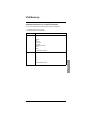
Supplying the module with power
Modbus module for ATV68 — View of underside
–
+
Power supply
24 V AC isolated
(± 10%) 280 mA max.
ENGLISH
The module is not supplied by the drive, but requires a separate power supply.
Note: The negative terminal of the 24 V power supply should be connected to the installation
earth.
87
Hardware Installation
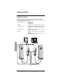
Connecting the module to the drive
The connection accessories should be ordered separately (consult the catalogue).
During installation, the module and drive should be switched off.
1 Use the VW3-A68313 cable.
2 Remove the ATV68 cover.
3 Attach the “ATV68” connector to the control card X4 connector (RJ45 port) and the “Gateway” connector to
the module RJ45 connector located closest to the front panel (marked “ATV68” on the following diagram).
ATV68 (control card)
VW3-A68303
Control
keypad
ATV68
Configuration
RJ45
(X4 connector)
ENGLISH
ATV68
Control
card
RJ45
VW3-A68313
88
Hardware Installation
It is possible to communicate with the ATV68 when its power is switched off (line switch or circuit-breaker
open).
To do this, it is necessary to connect an auxiliary control supply voltage:
• 24 V DC for the ATV68••N4 range (400 V/500 V)
• 230 V AC for the ATV68••Y range (690 V)
See the user manuals for how to connect the auxiliary control power supply.
Pin-out for the ATV68-module cable:
ENGLISH
ATV68 (RJ5)
(X4 port)
89
VW3-A68313 cable
Module (RJ45)
(ATV68 port)
Hardware Installation
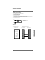
Connecting the module to the Modbus network
The connection accessories should be ordered separately (consult the catalogue).
Attach the cable 9-pin male SUB-D connector to the 9-pin female SUB-D connector on the module front panel,
as shown in the following diagram:
VW3 A68 303
ENGLISH
9-pin female
SUB-D
VW3 A68 313
90
Hardware Installation
Example of connection
The Schneider Electric catalogue offers a variety of accessories to simplify equipment connection.
Connection on TSXSCA62 and TSXSCA50 cable connectors is one example of the different options for
connecting Modbus (please consult our catalogues).
- Shielded double twisted pair cable:
TSXCSA100 (100 m)
TSXCSA200 (200 m)
TSXCSA500 (500 m)
- TSXSCA62
2-channel subscriber socket:
This passive box can be used for connection on two screw
terminals and two 15-pin female SUB-D connectors. It includes the
line termination required when the socket is located at the end of
the line.
- TSXCA50 junction box:
This passive box can be used for connection on three screw
terminals. It includes line termination.
- Drop cables:
VW3A8306 3 m long, equipped with 2 RJ45 and male SubD15
connectors.
VW3A8306D30 3 m long, equipped with an RJ45 connector,
stripped at the other end.
PLC
PC
ENGLISH
TSX CSA •00
VW3 A68 303
VW3 A68 313
VW3 A68 306
VW3 A68 306
VW3 A68 303
VW3 A68 313
TSX SCA 62
91
Hardware Installation
Wiring recommendations
•
•
•
•
•
Use a shielded cable with 2 pairs of twisted conductors
Link the reference voltages together
Maximum line length: 1000 metres
Maximum drop length: 20 metres
Cable routing: keep the bus separate from the power cables (30 cm minimum), make crossovers at right
angles if necessary, connect the cable shielding to the ground of each device
• Add line terminations at both ends
120 Ω
D(A)
1 nF
Line termination
recommended at both ends
D(B)
Pin-outs
• VW3A68306 cable for TSX SCA 62
9-pin female SUB-D
9-pin male SUB-D
NC
1
1
RS232 - TX (not used)
2
2
RS232 - RX (not used)
3
3
NC
4
4
GND (GALV)
5
+ 5 (GALV)
6
RS485 B-LINE
7
RS485 A-LINE
8
NC
9
GND
5
15-pin male SUB-D
ENGLISH
• Modbus module for ATV68
15
6
D(B)
7
14
D(A)
8
7
9
92
Hardware Installation
Configuring the communication functions
Configuration must be performed with the module switched off.
Both blocks of switches used to configure the communication functions are concealed behind the module
cover 5 (see Presentation section, page 85). To remove this cover, simply slide the tip of a small
screwdriver between the top of the cover and the module casing, then carefully remove the cover. Once the
cover has been removed, take care not to touch any electrical circuits or electronic components. Both blocks
of switches are represented schematically below, with each switch shown in its factory-set position:
Address
Speed
Parity
A switch is at state 0 when it is in the OFF position and state ON 1 when it is in the ON position.
Any modification to the module communication functions will only take effect when the module is next switched
on.
Note: When all the switches are in the OFF position, the LED 4 "Hardware Settings Status" turns red. This
also occurs if an configuration is incorrect.
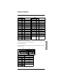
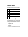
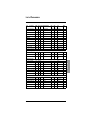
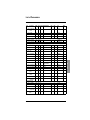
Coding the Modbus address
ENGLISH
An Altivar 68 is identified on a Modbus bus by its module address, coded from 1 to 31.
The drive address corresponds to the binary number given by the ON (1) or OFF (0) position of switches 1
(MSB) to 7 (LSB) in the block of 8 switches. It should be configured before the module is switched on:
Address
93
Speed
Parity
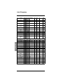
Hardware Installation
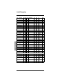
Switches
Modbus address
12345678
0000000x
1234
xxxx
Invalid configuration
0000001x
0000010x
0000011x
0000100x
0000101x
0000110x
0000111x
0001000x
0001001x
0001010x
0001011x
0001100x
0001101x
0001110x
0001111x
0010000x
xxxx
xxxx
xxxx
xxxx
xxxx
xxxx
xxxx
xxxx
xxxx
xxxx
xxxx
xxxx
xxxx
xxxx
xxxx
xxxx
1
2
3
4
5
6
7
8
9
10
11
12
13
14
15
16
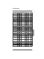
Switches
12345678
0010001x
0010010x
0010011x
0010100x
0010101x
0010110x
0010111x
0011000x
0011001x
0011010x
0011011x
0011100x
0011101x
0011110x
0011111x
0100000x
to
1111111x
1234
xxxx
xxxx
xxxx
xxxx
xxxx
xxxx
xxxx
xxxx
xxxx
xxxx
xxxx
xxxx
xxxx
xxxx
xxxx
xxxx
xxxx
Modbus address
17
18
19
20
21
22
23
24
25
26
27
28
29
30
31
Invalid
configurations
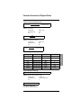
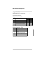
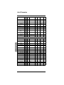
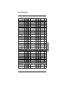
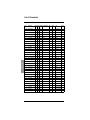
Coding the Modbus speed
The factory setting is 19,200 bps.
The value of this speed depends on switch 8 (MSB) in the block of 8 switches and switches 1 and 2 (LSB) in
the block of 4 switches.
Address
Switches
12345678
xxxxxxx0
xxxxxxx0
xxxxxxx0
xxxxxxx0
xxxxxxx1
xxxxxxx1
xxxxxxx1
xxxxxxx1
Speed
Parity
Modbus speed
1234
00xx
01xx
10xx
11xx
00xx
01xx
10xx
11xx
Invalid configuration
1,200 bps
2,400 bps
4,800 bps
9,600 bps
19,200 bps
Invalid configurations
94
ENGLISH
The module speed should be identical to that of the Modbus master.
Hardware Installation
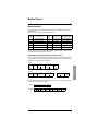
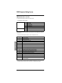
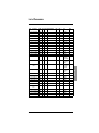
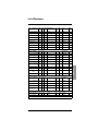
Coding the Modbus parity
The module parity should be identical to that of the Modbus master. The factory setting is no parity.
Address
Switches
12345678
xxxxxxxx
xxxxxxxx
xxxxxxxx
xxxxxxxx
1234
xx00
xx01
xx10
xx11
Speed
Parity
Modbus parity
Invalid configuration
No parity
Even
Odd
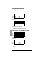
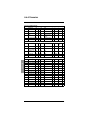
Examples of configuration
Address
Speed
Parity
ENGLISH
Address = 12
Speed = 9,600 bps
Parity = Even
Address
Speed
Parity
Address = 5
Speed = 2,400 bps
Parity = No parity
95
Signalling
1
2
3
4
VW3A68303
1
2
1 Bus Error
4
5
6
1 BUS ERROR
2 BUS READY
3 PROCESSING
4 HW SET. STAT.
5 SUBNET STATUS
6 DEVICE STATUS
6
5
3
2 Bus Ready
Red
Modbus error.
Green
More than 10% of requests have
an incorrect CRC value.
Modbus operating normally
Off
Modbus operational or module not
initialized
Off
Anomaly during module
initialization
Red
Modbus fault (time-out)
4 Hardware settings status
Flashing green
Receiving a Modbus request or
sending a Modbus response
Red
The module switches are all in the
OFF state
or
Incorrect configuration
Off
No request is being processed
Green
Switch hardware configuration
replaced by a software
configuration
Off
Switches OK and in use
5 Subnet Status
6 Device Status
Off
Module not supplied with power
Off
Module not supplied with power
Flashing green
Initializing the ATV68-module link
Green
Initializing the module
Green
ATV68-module link OK
Flashing green
Module operational
Red
ATV68-module link fault
Red
Module internal fault
Flashing green/ Configuration missing
red
Note : If the “DEVICE STATUS” LED flashes according to a sequence beginning with one or more red
flashes, you should make a note of the order in which this sequence occurs, and communicate this
information to Schneider Electric’s repair department.
96
ENGLISH
3 Processing
Notation Conventions
Value expressed in hexadecimal, equivalent to the notations H••••, ••••hex and 0x•••• sometimes
used in other documents
Example: 16#0100 = 256
2#••••
Value expressed in binary. The number of ‘•’ digits depends on the size of the represented data
item. Each 4-bit byte is separated from the others by a space
Examples: byte 2#0010 0111 = 39, word 2#0110 1001 1101 0001 = 16#69D1 = 27089
••••
Decimal values are written without a prefix
Lo
Low-order byte in a word or low-order word in a double word
Hi
High-order byte in a word or high-order word in a double word
f
Frequencies (Hz or submultiple)
n
Speed of rotation (rpm)
Wxxx
Address of a Modbus word
Wxxx:y
Bit y of Modbus word xxx
Example: W0: 12 = bit 12 of word 0
ENGLISH
16#••••
••••h
97
Parameter Conversion to Physical Values
N2 type of data (16-bit standardized value)
Parameter value
Physical value =
x Standardization factor
16384.0
Example 1: Output frequency
Parameter value
16#09C4 = 2500
Standardization factor
163.84
Unit
Hz
Frequency =
2500
x 163.84 = 25.0 Hz
16384.0
Example 2: Power output on the motor shaft
Parameter value
16#1333 = 4915
Standardization factor
400.0
Unit
kW
4951
Power =
16384.0
x 400.0 = 120 kW
%
Binary
Hexadecimal
Decimal
199,9939
2#0111 1111 1111 1111
16#7FFF
32767
100,0000
2#0100 0000 0000 0000
16#4000
16384
0.0061
2#0000 0000 0000 0001
16#0001
1
0.0000
2#0000 0000 0000 0000
16#0000
0
-0.0061
2#1111 1111 1111 1111
16#FFFF
-1
-100,0000
2#1100 0000 0000 0000
16#C000
-16384
-200,0000
2#1000 0000 0000 0000
16#8000
-32768
ENGLISH
Example 3: Percentage
T2 type of data (time constant 16)
Physical value = Parameter value x Standardization factor
Example 4: Display of acceleration time (T2 type of data)
Parameter value
16#0064 = 100
Standardization factor
0.005 (5 ms internal clock)
Unit
s
Time = 100 dec x 0.005 s = 0.5 s
Other types of data (02, V2)
It is not necessary to repeat standardization.
98
Modbus Protocol
RTU mode
The transmission mode used is RTU mode. The frame does not contain a message header byte, nor any end
of message bytes. It is defined as follows:
Slave
address
Request code
Data
CRC16
The data is transmitted in binary.
CRC16: cyclical redundancy check.
The end of the frame is detected after a silence ≥ 3 characters.
Principle
Modbus protocol is a master-slave protocol.
ENGLISH
Master
Slave i
There can only be one device on the line which is sending a message.
The master manages the exchanges and only it can take the initiative.
It interrogates each of the slaves in succession.
No slave can send a message of its own accord without having been requested.
The master repeats the question if there is an incorrect exchange, and decrees
that the interrogated slave is missing after failure to respond within a given time
period.
If a slave does not understand a message, it sends an exception response to
the master. The master can repeat the request or not.
Slave j
Slave k
Direct slave-to-slave communications are not possible.
For slave-to-slave communication, the master application software must have been designed to permit this:
interrogating one slave and sending the data received to the other slave.
Two types of dialog are possible between master and slaves:
• the master sends a request to a slave and waits for its response
• the master sends a request to all the slaves without waiting for a response (broadcast communication
principle)
Addresses
• The drive Modbus address can be configured from 1 to 31
• Address 0 coded in a request sent by the master is reserved for broadcast communication. ATV68 drives
take account of the request, but do not respond to it
• When the ATV68 is configured with address 0 (default value), it does not respond
99
Modbus Protocol
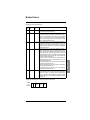
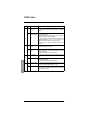
Modbus functions
The following table indicates which Modbus functions are managed by the Modbus module for ATV68, and
specifies the limits.
The "read" and "write" functions are defined as seen by the master.
Code
(decimal)
Function name
Broadcast
comm.
Max. value of N
Modbus standard name
3
Read N output words
NO
11 words max.
Read Holding Registers
4
Read N input words
NO
11 words max.
Read Input Registers
6
Write one output word
YES
—
Preset Single Register
8
Diagnostics
NO
—
Diagnostics
16
Write N output words
YES
11 words max.
Preset Multiple Regs
The content of the frames described below is systematically expressed in hexadecimal notation. The “16#”
prefix has therefore been left out to make it easier to read.
Read N output words or N input words: functions 3 and 4
Function 3 is used to read output words (words which can be written and read by the master in the slave),
whereas function 4 is used to read input words (word which the master can only read). Apart from their
respective code, these two functions are strictly identical.
Request
03 or 04
1 byte
No. of the 1st word Number of words
Hi
Lo
Hi
Lo
2 bytes
2 bytes
CRC16
2 bytes
ENGLISH
Slave
no.
1 byte
Response
Slave
no.
1 byte
03 or 04
1 byte
Value of 1st word
Hi
Lo
2 bytes
Number of bytes
read
1 byte
-------
Value of last word
Hi
Lo
2 bytes
CRC16
2 bytes
Example: read 5 words W6 to W10 (monitoring PZD2 to PZD6) in slave 2. The number of bytes read and
present in the slave response equals 10 (16#0A).
Question
02
03
0006
Response
02 03 0A
Value of:
0005
25BC
W6
65FB
10C0
W7
0000
W8
7CD1
W9
457C
W10
EB10
100
Modbus Protocol
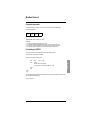
Write one output word: function 6
Function 6 is used to write an output word (word which can be written and read by the master in the slave).
Request and response (the frame format is identical)
Slave
no.
1 byte
Word number
Hi
Lo
2 bytes
06
1 byte
Word value
Hi
Lo
2 bytes
CRC16
2 bytes
Example: write value 16#004D (77 in decimal notation) in word W1032 (1032 = 16#0408) of slave 2 (bus
Link reference 3 = 77).
Question
and
Response
02
06
0408
004D
C93E
Diagnostics: function 8
Function 8 is used to read the value of one of the internal event counters of the Modbus module for ATV68 or
to ask it to perform diagnostic commands. The code for this function is always accompanied by a sub-code,
thus characterizing a diagnostic sub-function. The complete list of sub-codes that can be used with the Modbus
module for ATV68 is given in a table appearing after the description of the request and response frames. A
second table contains the descriptions of these sub-functions, as well as the data they use. Finally, the
description of the “diagnostics” function ends with a short example (sub-function 0: echo of the master’s
request).
ENGLISH
Request
Slave
no.
1 byte
08
1 byte
Sub-code
Hi
Lo
2 bytes
Request data
Hi
Lo
2 bytes
Sub-code
Hi
Lo
2 bytes
Request data
Hi
Lo
2 bytes
CRC16
2 bytes
Response
Slave
no.
1 byte
08
1 byte
CRC16
2 bytes
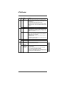
Sub-codes (decimal notation) and diagnostic sub-functions
SubCode
Name of diagnostic sub-function
Modbus standard name
0
Echo of the master’s request
Return Query Data
10
Reset counters and diagnostics
Clear Counters and Diagnostic Register
12
Read number of requests received with checksum
error
Return Bus Communication Error Count
13
Read number of exception responses
Return Bus Exception Error Count
14
Read number of requests addressed to the slave
Return Slave Message Count
101
Modbus Protocol
Diagnostic sub-function data and description
SubCode
Request
Data
Response
Data
0
XX
YY
XX
YY
This sub-function asks the interrogated slave to return, in its response, all
the request data sent by the master (XX YY).
10
—
—
—
—
This sub-function asks the slave to reset the monitoring counters and the
status indicators relating to its exchanges, ie. the Modbus error counters.
These counters include those which are used by the other diagnostic
functions, ie. the “CRC Error Counter”, “Exception Illegal Function
Counter”, “Exception Illegal Address Counter”, “Exception Data Value
Counter” and “Received Queries Counter”.
12
—
—
XX
YY
Reads the value (XX YY) of a 16-bit counter totalizing the number of
requests received, with CRC error, by a slave. This error counter, “CRC
Error Counter”, is reset when the drive is switched on or the slave is
restarted, as well as on execution of a “reset counters and diagnostics”
command (sub-function 10).
13
—
—
XX
YY
Reads the sum (XX YY) of 16-bit counters totalizing the number of
exception responses sent by the slave to a Modbus master. The three
exception response counters affected by this sub-function, “Exception
Illegal Function Counter”, “Exception Illegal Address Counter” and
“Exception Data Value Counter”, are reset when the drive is switched on
or the slave is restarted, as well as on execution of a “reset counters and
diagnostics” command (sub-function 10).
The first three types of exception response, described below and
characterized by their error code, cause incrementation of one of the
three counters presented above:
• The “Exception Illegal Function Counter” counter is incremented by
exception responses with error code = 1.
• The “Exception Illegal Address Counter” counter is incremented by
exception responses with error code = 2.
• The “Exception Data Value Counter” counter is incremented by
exception responses with error code = 3.
14
—
—
XX
YY
Reads the value (XX YY) of a 16-bit counter totalizing the number of
requests addressed to the slave, whatever their type, including requests
broadcast to all slaves. This request counter, “Received Queries
Counter”, is reset when the drive is switched on or the slave is restarted,
as well as on execution of a “reset counters and diagnostics” command
(sub-function 10).
Example: echo requested for slave 2, with the value 16#53DC for the echo data.
Request
and
Response
02
08
0000
53DC
DD51
102
ENGLISH
Function performed
Modbus Protocol
Write N output words: function 16 (16#10)
Function 16 is used to write output words (words which can be written and read by the master in the slave).
Request
Slave
no.
10
1 byte
1 byte
No. of the Number of
Number of
1st word
words
bytes
Hi
Lo
Hi
Lo
2 bytes
2 bytes
1 byte
Value of
1st word
Hi
Lo
2 bytes
------
Value of
last word
Hi
Lo
2 bytes
CRC16
2 bytes
Response
Slave
no.
10
1 byte
1 byte
No. of the Number of
1st word
words
Hi
Lo
Hi
Lo
2 bytes
2 bytes
CRC16
2 bytes
Example: write values 16#0020 and 16#0100 (32 and 256 in decimal notation) in words W1032 and W1033
(16#0408 and 16#0409) of slave 2 (bus Link Reference 3 = 32 and bus Link Reference 4 = 256).
Request
ENGLISH
Response
103
02 10
0408
0002
04
Values to be written at addresses:
02
10
0408
0002
0020
W1032
C109
0100
W1033
CFD7
Modbus Protocol
Exception responses
An exception response is returned by a slave when it cannot execute the request addressed to it.
Exception response format:
Slave
no.
Response
code
Error
code
CRC16
1 byte
1 byte
1 byte
2 bytes
Response code: request function code + 16#80.
Error code:
1 = The function requested is not recognized by the slave.
2 = The bit and word addresses indicated when the request is made do not exist in the slave.
3 = The bit and word values indicated when the request is made are not permitted in the slave.
4 = The slave has begun to execute the request, but cannot continue processing it fully.
Calculating the CRC16
The CRC16 is calculated on all message bytes by applying the following method:
Initialize the CRC (16-bit register) with 16#FFFF.
From the 1st message byte to the last, enter:
XOR
Enter
8 times
<byte> —> CRC
ENGLISH
CRC
Shift the CRC one bit to the right
If the output bit = 1, enter CRC XOR 16#A001—> CRC
End of
entry
End of
entry
The CRC obtained will be sent with the least significant bits first, then the most significant bits (unlike the other
data contained in the Modbus frames).
XOR = exclusive OR.
104
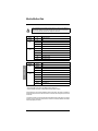
Module Modbus Data
Only the addresses and values defined in this document can be used. Any other address or
value should be considered as reserved and should never be the object of a write operation.
Failure to comply with this precaution risks causing drive malfunctions.
Service
Input words
Module
W0
Module status word
Response
PKW
W1
PKE
W2
IND
W3
PWE Hi
W4
PWE Lo
W5
ETA status word
W6
Actual value 1 AO/AI
W7
Actual value 2 AO/AI
W8
Actual value 3 AO/AI
W9
Actual value 4 AO/AI
W10
Actual value 5 AO/AI
ENGLISH
Monitoring
PZD
Description
Service
Output words
Request
PKW
W1025
PKE
W1026
IND
W1027
PWE Hi
W1028
PWE Lo
W1029
CMD control word
W1030
Main reference 1
W1031
Aux. reference 2
W1032
Aux. reference 3
W1033
Aux. reference 4
W1034
Aux. reference 5
Control
PZD
Description
To ensure consistency of the data, it is advisable to:
• Read all accessible input words in a single Modbus exchange (W0 to W10)
• Write all accessible output words in a single Modbus exchange (W1025 to W1034)
These exchanges only occur between the Modbus master and the module. The module is responsible for
transferring the output word values to the ATV68 to which it is connected, then retrieving the input word values
from the drive.
It is important to maintain cyclic communication between the Modbus master and the module, even when the
user does not need to modify either the drive status or commands. This avoids the Modbus communication
timeout being tripped by the module.
105
Module Management
Bits
Name and Identifier
Description
15-13
—
Reserved
12
Subnet Status
= 0 : ATV68-module link not started or faulty
= 1 : ATV68-module link OK
11-0
—
Reserved
ENGLISH
Module status word (W0)
106
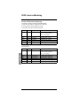
ATV68 Control and Monitoring
Principle of ATV68 control and monitoring
The ATV68 drive is controlled in accordance with the PROFIDRIVE standard.
Two status charts are presented here: a simplified chart and a complete chart.
The common states of these charts are identified in the same way.
The PLC output words are used to control the drive (control PZD):
Control
Word
Description
Assignment
PZD1
W1029
CMD control word
B6.21:
• bits 0 to 10: Profidrive standardized
• bits 11 to 15 *: assignable
PZD2 *
W1030
Main reference 1
B6.06 (default value = not used)
PZD3 *
W1031
Aux. reference 2
B6.07 (default value = not used)
PZD4 *
W1032
Aux. reference 3
B6.08 (default value = not used)
PZD5 *
W1033
Aux. reference 4
B6.09 (default value = not used)
PZD6 *
W1034
Aux. reference 5
B6.10 (default value = not used)
ENGLISH
The PLC input words are used to find out what stage the drive is at, and also which drive values have been
read (monitoring PZD):
Monitoring
Word
Description
Assignment
PZD1
W5
ETA status word
B6.26:
• bits 0 to 10: Profidrive standardized
• bits 11 to 15 *: assignable
PZD2 *
W6
Actual value 1 AO/AI
B6.11 (default value = Output frequency)
PZD3 *
W7
Actual value 2 AO/AI
B6.13 (default value = Output speed)
PZD4 *
W8
Actual value 3 AO/AI
B6.15 (default value = Output current)
PZD5 *
W9
Actual value 4 AO/AI
B6.17 (default value = Output torque)
PZD6 *
W10
Actual value 5 AO/AI
B6.19 (default value = Output power)
107
ATV68 Control and Monitoring
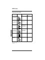
ETA Status Word bits
15…12 *
11…8 *
7…4
3…0
ETA
masked
Mask
0 Not ready to switch on
xxxx
xx1x
x0xx
0000
16#0200
16#024F
1 Ready to switch on
xxxx
xx1x
x0xx
0001
16#0201
16#024F
3 Ready to run
xxxx
xx1x
x0xx
0011
16#0203
16#024F
xxxx
xx1x
x011
0111
16#0207
16#0237
16#024F
16#027F
19 Lock switching on
xxxx
xx1x
x1xx
0000
16#0240
16#024F
20 Fault
xxxx
xx1x
x0xx
1000
16#0208
16#024F
List of main states:
7
Run
x : Bit state can be 0 or 1.
108
ENGLISH
Simplified Profidrive status chart
ATV68 Control and Monitoring
Complete Profidrive status chart
ENGLISH
For more information, see the "F3 menu" in the programming manual.
109
ENGLISH
ATV68 Control and Monitoring
110
ATV68 Control
Description of the CMD control word
Bit 15
Bit 14
Bit 13
Bit 12
5 free bits
which can be configured for
internal or external commands
ENGLISH
Bit 11
Bit 10
Control by communication link enabled
Control by communication link disabled
Bit 9
---
---
Bit 8
Activate Jog 1
Disable Jog 1
Bit 7
External reset
---
Bit 6
Activate reference
Disable reference
Bit 5
Release ramp
Inhibit ramp
Bit 4
Activate ramp output
Disable ramp output
Bit 3
Enable operation (unlock)
Inhibit operation (lock/freewheel)
Bit 2
Operating condition
OFF 3 (fast stop)
Bit 1
Operating condition
OFF 2 (lock/freewheel stop)
Bit 0
On (run)
OFF1 (stop on ramp)
=1
=0
111
Bit
Value
Meaning
Comment
0
1
ON
Controls the change of the device status from "1 Ready to switch on" to
"3 Ready to run", if the "power capacitor" stage (DC bus) has already
been charged.
If the "line contactor control" function is active, the device status
changes to "2 Charge bus DC" while the capacitors are charging, and
changes to "3 Ready to run" when the DC bus capacitors are charged.
0
OFF 1 (stop on
ramp)
After accepting the command, the device status changes to "13 OFF1
active" and stops the motor in accordance with the deceleration ramp.
When the output frequency reaches 0 Hz, the device status changes,
passing through "0 Not ready to switch on", to "1 Ready to switch on",
if the basic command (bit 1 = 0, bit 2 = 1, bit 3 = 1 and bit 10 = 1) is
applied.
If a new ON command is sent during the deceleration phase, the value
of the reference applied is executed in accordance with the acceleration
ramp. The device status therefore changes to "7 Run".
If the "line contactor control" function is active, the contactor is disabled
on switching to "1 Ready to switch on".
1
Operating
condition
"OFF2" command disabled.
Command required to authorize operation.
0
OFF2 (lock/
freewheel stop)
After accepting the command, the drive is locked, and the status
changes to "19 Lock switching on".
If the “line contactor control” function is active, the contactor is disabled.
The OFF2 command can also be sent using the bus connector "Unlock"
function. When the basic command (bit 1 = 0, bit 2 = 1, bit 3 = 1 and bit
10 = 1) is applied, the device status changes to "1 Ready to switch on".
1
Operating
condition
"OFF3" command disabled.
Command required to authorize operation.
0
OFF3
(fast stop)
After accepting the command, the device status changes to "14 OFF3
active", producing the fastest possible motor stop at maximum power or
at maximum voltage of the power capacitor stage (DC bus).
When the output frequency reaches zero Hz, the device status changes
to "19 Lock switching on".
If the “line contactor control” function is active, the contactor is disabled.
If the OFF3 command (bit 2 = 1) is cancelled during deceleration, the
fast stop is still performed.
1
2
112
ENGLISH
ATV68 Control
ATV68 Control
Bit
Value
Meaning
Comment
3
1
Enable operation
(unlock)
After accepting the command, the drive is activated in the "3 Ready to
run" (lock) status and the device status changes to "4 Operation
enabled".
0
Inhibit operation
(lock/freewheel)
After accepting the command, the drive is locked, and the device status
changes to "3 Ready to run".
If the device status "13 OFF1 active" is applied, the drive is locked, and
the status "0 Not ready to switch on" is applied.
If the “line contactor control” function is active, the contactor is disabled.
If the basic command (bit 1 = 0, bit 2 = 1, bit 3 = 1 and bit 10 = 1) is
applied, the device status changes to "1 Ready to switch on".
If the device status "14 OFF3 active" is applied, the action is still
performed.
1
Activate ramp
output
Device status "5 Ramp output active", the motor accelerates in
accordance with the acceleration ramp.
0
Disable ramp
output
After accepting the command, the ramp output is reset. The motor
stops at maximum power or at the maximum voltage for the power
capacitor stage (DC bus).
The device status changes to "4 Operation enabled".
1
Release ramp
Activation of status "6 Ramp release", used to unblock changes in the
ramp.
0
Inhibit ramp
After accepting the command, the after-ramp reference value is
blocked, and stops changing.
The device status changes to "5 Ramp output active".
1
Activate reference After accepting the command, the selected reference value is used on
the ramp input. The device status changes to "7 Run".
0
Disable reference
4
ENGLISH
5
6
113
After accepting the command, the ramp input is reset. This produces
motor deceleration in accordance with the ramp set. The device status
changes to "6 Ramp release".
Bit
Value
Meaning
Comment
7
1
External reset
The external reset command is accepted, on a positive state "20 Trip".
When the current fault has been cleared, the status changes to "19
Lock switching on".
If the fault persists, the device status remains "20 Trip".
The external reset command can also be sent via the bus connector
"External reset" function, and via the red STOP/Reset button located on
the keypad.
0
—
1
Activate Jog 1
The command Activate Jog 1 is only accepted if the device status is "4
Operation enabled". For this reason, the motor accelerates as fast as
possible to the frequency of the parameter in C1.13; the device status
changes to "11 Jog 1 active".
0
Disable Jog 1
The command is only accepted if "Activate Jog 1" has previously been
set to "1". The motor returns to zero Hz as fast as possible, then
changes to the state "12 Jog 1 Pause".
If a new Jog 1 stop command is sent within two seconds, it is
immediately executed.
At the end of the "Jog Timer" 2 seconds, the device status returns to the
initial status "4 Operation enabled".
1
Activate Jog 2
Command not available
0
Disable Jog 2
Command not available
1
Control by
communication
link enabled
The drive is controlled by the PLC via Modbus.
The control process data is now valid.
0
Control by
communication
link disabled
The reaction depends on bit 9 of the ETA status word.
Bit 9 = 0 (local mode).
The drive is in local mode, the PLC can only perform monitoring.
Bit 9 = 1 (control by communication link expected).
The drive is in communication link mode, the ATV68 trips on "LS2
Loss". The drive reaction depends on the setting of parameter B6.03
"Type of stop on TO". An alarm is always sent.
8
9
10
114
ENGLISH
ATV68 Control
ATV68 Control
Summary of the main commands
Function
CMD control word
Binary
Hexadecimal
ON
0000 0100 0111 1111
047F
OFF 1
0000 0100 0111 1110
047E
Stop in accordance with
the deceleration ramp
basic command
OFF 2
0000 0100 0111 1101
Lock (freewheel stop)
produces the status
"19 Lock switching on"
OFF 3
0000 0100 0111 1011
Fast deceleration is
performed up to the DC
bus current or voltage
limits
produces the status
"19 Lock switching on"
Jog 1
0000 0101 0000 1111
050F
Reset
(External reset)
xxxx x1xx 1xxx xxxx
example:
0480
ENGLISH
Starting in accordance
with the acceleration
ramp
Key:
F/n = frequency or speed
Ver = lock
115
047D
047B
ATV68 Control
Assignment of the free bits 11 to 15 of the CMD control word
Bits 11 to 15 of the control word (CMD) are not fixed by Profidrive; they can be assigned to:
• internal commands (conforming to use of the logic input)
• external commands in a totally separate way from the ATV68 functions, for the transmission of data via the
logic outputs (bit 10 of the CMD control word should be at 1)
Use
Free bits of the CMD control word
"Internal"
Logic input A
Logic input B
Logic input C
Manual/Auto
2nd Ramp
External Trip
EXT-Mot.Trip
EXT-T Limit
PID-enable
Mains ON(OFF)
…
(See parameters B6.21 to B6.25)
"External"
D4.00: 24V logic output
D4.01: Relay output 1
D4.02: Relay output 2_2
D4.03: Relay output 3_2
(See configuration of logic outputs)
Communication link references 1 to 5 can be assigned to:
•
•
internal values, such as for example speed reference "Freq.ref.man" and reference "PID-ref"; assignments
made using parameters B6.06 to B6.10 respectively, for communication link references 1 to 5.
external values, for the analogue outputs, without influencing control of the ATV68 (bit 10 of the CMD
control word should equal 1 so that this data can be taken into account by the ATV68); assignments made
using parameters D3.00 (for AO1) and D3.04 (for AO2), taking care that parameter B6.06 to B6.10 which
corresponds to the communication link used be left as "not assigned". For these "external" values, it is
possible to assign the same communication link reference to both analogue outputs AO1 and AO2, but
there is no particular advantage to be gained.
Use
Communication link references
"Internal"
Freq.ref.man
Freq.ref.aut
F-ref correction
Torque limit
PID-ref.
Actual PID Feedback Val.
(See parameters B6.06 to B6.10)
"External"
D3.00: Analogue output 1 (AO1)
D3.04: Analogue output 2_2 (AO2)
(See configuration of analogue outputs)
The reference values are presented as standardized linear values (N2).
116
ENGLISH
Assignment of communication link references
ATV68 Monitoring
Description of the ETA status word
Bit 15
Bit 14
Bit 13
5 free bits which can be configured
for internal or external states
Bit 12
Bit 11
Threshold attained
Below the threshold
Bit 9
Control by communication link expected
Locked
Bit 8
Reference reached
Outside reference
Bit 7
Alarm
No alarm
Bit 6
Lock switching on
Switching on enabled
Bit 5
OFF 3 No
OFF 3 (fast stop)
Bit 4
OFF 2 No
OFF 2 (lock)
Bit 3
Trip
Trip inv.
Bit 2
Operation Enable
Operation inhibited
Bit 1
Ready to RUN
Not ready to run
Bit 0
Ready to switch on
Not ready to switch on
=1
=0
ENGLISH
Bit 10
117
ATV68 Monitoring
Bit
Value
Meaning
Comment
0
1
Ready to switch on
The device status is "1 Ready to switch on".
The drive is locked.
If the “line contactor control” function has been activated, the line
contactor is disabled.
0
Not ready to switch
on
The device status is "0 Not ready to switch on" or "19 Lock switching
on".
1
Ready to run
The device status is "3 Ready to run ". This means that the DC Bus
stage is powered up, and there are no faults. However, the drive
remains locked.
If the "line contactor control" function has been activated, this control
message is sent during the power capacitor charging phase: "2 Charge
bus DC".
0
Not ready to run
1
Operation enabled
0
Operation inhibited
1
Trip
0
Trip inv.
1
OFF2 No
0
OFF2 (lock)
1
OFF3 No
0
OFF3 (Fast Stop)
An OFF3 command has been sent.
1
Lock switching on
This state is obtained by the commands OFF2, OFF3 and "Enable
operation" of the CMD control word, after the fault has been reset. This
status is cleared by setting the parameters for bit 0 of the CMD control
word = 0.
2
3
4
5
6
The states are "4 Operation enabled", "5 Ramp output active", "6 Ramp
release", "7 Run", "13 OFF1 active", or "14 OFF3 active".
The ATV68 is unlocked, the power bridge (IGBT) is active, the output
terminals are powered up.
Fault present. The device status is "20 Trip". After the fault has
disappeared and been reset, the status changes to "19 Lock switching
on".
ENGLISH
1
An OFF2 command has been sent.
With bit 1 of the CMD control word (OFF1), the "Lock switching ON"
status no longer applies.
7
0
Switching on
enabled
1
Alarm
0
No alarm
An alarm has been sent, there is no need for an external reset.
118
ATV68 Monitoring
Bit
Value
Meaning
Comment
8
1
Reference reached
Comparison of the reference value and the actual value of
the frequency or the speed. The tolerance band and time delay for
starting and de-energization depend on parameter D4.08.
0
Outside reference
1
Control by
communication link
expected
When the ATV68 has been configured for "bus" mode using parameter
B6.01, it asks the Modbus master to accept commands once the drive
has been switched on (power or control).
If the master does not accept commands, an alarm (ETA bit 7) is sent.
0
Locked
The ATV68 has changed to local mode (control via the programming
terminal keypad or via the terminals defined in local mode).
If the master does not send a command via the communication link
(CMD bit 10 = 0), an alarm is sent.
If the drive is switched to remote mode again, the PLC should respond
with a command via the communication link within 2 seconds,
otherwise the drive is automatically switched back to local mode.
1
Threshold reached
The actual value of the frequency is ≥ the threshold in D4.06
0
Below the threshold The actual value of the frequency is ≤ the threshold in D4.07
9
ENGLISH
10
119
ATV68 Monitoring
Assignment of the free bits 11 to 15 of the ETA status word
Bits 11 to 15 of the ETA status word are not fixed by Profidrive, and they can be assigned to:
Use
Free bits of the ETA status word
"Internal"
Ready
Run
Trip
Ready+Run
Alarm
Generat.oper
Contactor control
Local (remote)
Motor frequency > threshold
Lift Brake
Output C1
…
(See parameters B6.26 to B6.30)
"External"
DI1
DI2
DI3
DI4
DI6_2
DI7_2
DI8_2
…
(See parameters B6.26 to B6.30)
ENGLISH
• internal states (conforming to the logic outputs)
• external states separate from the ATV68 functions
120
ATV68 Monitoring
Assignment of actual values
Actual values can be assigned to:
•
internal actual values, such as the frequency output “f- out (signed)”, the output current “Out.current”, etc.
(conforming to the ATV68 analogue outputs).
•
external actual values (commands) coming from the analogue inputs, for external use by the Modbus
master, without influencing control of the ATV68 (bit 10 of the CMD control word should be set to 1 so that
this data can be made available to the Modbus master by the drive).
ENGLISH
Actual values, like communication link reference values, are presented as standardized linear values (in Hz or
as a %) (N2).
Use
Actual values
"Internal"
Output freq. (signed)
Output freq. (unsigned)
Out.current
Torque (signed)
Torque (unsigned)
Motor power
Motor voltage
N-out sig (signed)
N-out sig (unsigned)
Internal frequ. reference
Torque limit reference
PID-ref.
PID-feedback
PID-error
DC-voltage
Fault number
Drive status
…
(See parameters B6.11 to B6.20)
"External"
Analogue input AIC
Analogue input AI_2
Analogue input AIV
…
(See parameters B6.11 to B6.20)
121
Managing Communication Errors
Managing communication errors on the Modbus network
When the Modbus connection is lost, the module can no longer communicate with the Modbus master.
However, the connection to the drive remains operational and the module continues to communicate with it.
All the values of the PZD and PKW output data transmitted to the drive are reset when the Modbus time-out
trips on the module. The duration of this time-out equals 10 seconds.
These resets include resetting Bit 10 of the CMD control word (W1029), and hence activation of “control by
communication link disabled”.
Managing communication errors on the ATV68-module link
When the ATV68-module link is lost, the module can no longer communicate with the drive. However, the
connection with the Modbus network remains operational.
• The drive trips at the end of 10 s + x s.
The type of fault or stop on timeout applied by the drive can be configured by parameter B6.03 (BUS fault).
The value of x can be adjusted by parameter B6.04 (B6.03 Time delay).
• A second module time-out trips at the end of 10 s. From then on, all the PKW and PZD input word values
transmitted to the Modbus master by the module are reset:
W1 to W10 = 16#0000
Example 1
• B6.03 = Fault / B6.04 = 4.0 s
If communication between the module and the drive is interrupted for more than 14 s, the drive performs a
freewheel stop and the fault relay trips, changing to the “20 – Trip” status. To be able to control the drive
again, the following sequence should be sent by the control word:
- CMD = 16#x4FF = External reset, then
- CMD = 16#x47E = Basic command
Example 2
• B6.03 = Deceleration / B6.04 = 5.0 s
If communication between the module and the drive is interrupted for more than 15 s, the drive stops on a
ramp. The fault relay does not trip. To be able to control the drive again, the following value should be sent
by the control word:
- CMD = 16#x47E = Basic command
122
ENGLISH
• The whole time that communication is stopped, the module informs the Modbus master, via bit 12 of the
module status word (W0), that the ATV68-module link is no longer active (bit 12 = 0).
PKW Parameter-Setting Service
PKW, or configuration and adjustment process data, consist of 4 consecutive input and output words. They are
used to read and write the drive parameter values.
Request PKW
Address
Words
Fields
Request code
W1025
PKE
Parameter address
AK
15
PNU
12
11
10
IND
Reserved
W1027
PWE Hi
High order parameter value
W1028
PWE Lo
Low order parameter value
Response PKW
Address
Words
Fields
Response code
W1
PKE
Parameter address
AK
15
ENGLISH
0
W1026
PNU
12
11
10
0
W2
IND
Reserved
W3
PWE Hi
High order parameter value
W4
PWE Lo
Low order parameter value
or
Error code
Principles for processing the PKW request/response
To perform a complete transaction, the Modbus master must first write the PKW request (W1025 to W1028),
then read the PKW response words (W1 to W4) in an iterative manner, so long as the response corresponding
to the PKW request is not available (comparison of the values of PKE and IND in the request and in the
response).
The ATV68 retains its response values until the master formulates a new request, or until the communications
change to downgraded mode.
• The master must identify the response to its request:
a) by evaluating the response code
b) by evaluating the parameter number (PNU)
c) if necessary by evaluating the parameter index
d) if necessary by evaluating the parameter value
• If there is no need to exchange information via PKW message handling, the master should use the "No
command" request code.
• If the response code is 7 (error), a request code 0 (no command) must be sent to clear the error and be able
to address this same parameter again.
123
PKW Parameter-Setting Service
Saving to the Flash EPROM
The modified parameters are not saved automatically in the event of loss of the electrical line supply. They are
saved in the EPROM using the "PNU 971 – Record saved" parameter.
To launch this procedure, the parameter value should be at 1.
After saving, the parameter should be reset to 0.
AK Request codes (master ➞ ATV68)
Request code
Meaning
0
No request
1
Read a parameter value
Response code
pos.
neg.
0
7
1.2
7
2
Write a parameter value (word)
1
7
3
Write a parameter value (double word, floating point)
2
7
6
Read the value of the table parameter
4.5
7
Only descriptive elements with a maximum length of 4 bytes can be transmitted to the PKW part.
AK Response codes (master ➞ ATV68)
Meaning
0
No response
1
Correct reading or writing of a parameter value (word)
2
Correct reading or writing of a parameter value (double word,
floating point)
4
Correct reading of a parameter value (word table)
5
Correct reading of the parameter value (double word table)
7
Error
ENGLISH
Response code
124
PKW Parameter-Setting Service
PWE Parameter value - error code
The PWE field contains either the parameter value or the error code.
• The following types of data are possible:
For simple variables:
For table:
N2
16-bit standardized linear value
O2
16-bit unsigned
T2
16-bit time constant
NF
32-bit floating point
V2
16-bit sequence
OS4[ ]
String of 4 bytes (ASCII character table)
O2[ ]
16-bit unsigned
Font: Characters (text) should be represented using the ISO/IEC 10367 Latin Alphabet character table no. 1
(= Windows font).
• In the event of an error response code (AK = 7), PKE Lo contains an error code.
ENGLISH
Error code
Meaning
0
Incorrect logic address
1
Parameter writing refused
2
Value outside max. and min. limit
3
Error in the sub-index
4
No table
5
Incorrect type of data
9
Descriptive data not available
11
No parameter-setting priority for parameter (1)
13
Impossible to read text (or text table) during cyclic network operation
14
Impossible to read name during cyclic network operation
17
Request not taken into account because drive not locked
101
Incorrect request code (request not supported)
103
Access to parameter blocked by code
104
Unable to adjust the parameter, value or assignment already used
105
Type of table
106
Impossible to execute the request because Macro User 2 active or parameter locked
(logic input). See B2.04
(1) This error will always be returned by the drive if the Modbus master attempts to access a parameter when
parameter F6.02 has not been set to value 2 (Access mode = via RS232) from the terminal.
125
PKW Parameter-Setting Service
ASCII Code table
ISO/IEC 10 367 – Basic set GO – Additional set Latin Alphabet no. 1
Char.
hex
Char.
hex
Char.
hex
Char.
hex
Char.
hex
Char.
Space
ENGLISH
hex
126
PKW Parameter-Setting Service
Example 1: Reading the mechanical power (Menu A2.04, PNU 114)
Request
PKE
W 1025
16#
1072
IND
W 1026
16#
0000
PWE Hi
W 1027
16#
0000
PWE Lo
W 1028
16#
0000
Request code 1: Read a parameter value.
PNU = 114 = 16#72
Response
PKE
W1
16#
1072
IND
W2
16#
0000
PWE Hi
W3
16#
0000
PWE Lo
W4
16#
1333 = 4915
Response code 1: Correct reading of a parameter value.
Parameter A2.04 is described on page 80:
- Type N2
- Standardization factor B3.00 (Nominal power), 400 kW in the example
Physical value = 4915/16384.0 X 400 (standardization factor, eg. motor Pn) = 120 kW.
ENGLISH
Example 2: Reading the causes of faults (Menu A2.04, PNU 823)
Request
PKE
W 1025
16#
1337
IND
W 1026
16#
0000
PWE Hi
W 1027
16#
0000
PWE Lo
W 1028
16#
0000
Request code 1: Read a parameter value.
PNU = 823 = 16#337
Response
PKE
W1
16#
1337
IND
W2
16#
0000
PWE Hi
W3
16#
0000
PWE Lo
W4
16#
0039 = 57
Response code 1: Correct reading of a parameter value.
Parameter F3.03 is described on pages 64 and 80:
- Type O2
- Value 57: 4/20 mA fault
127
PKW Parameter-Setting Service
Example 3: Writing the max. value of the analogue output (Menu D3.03,
PNU 453)
Request
PKE
W 1025
16#
21C5
IND
W 1026
16#
0000
PWE Hi
W 1027
16#
0000
PWE Lo
W 1028
16#
6000
Request code 2: Write a parameter value.
PNU = 453 = 16#1C5
Value to be written: 150 %
Parameter D3.03 is described on page 88:
- Type N2
- Standardization factor 100.0
Value of PWE = 150 / 100 * 16384.0 = 24576 = 16#6000.
Response
PKE
W1
16#
11C5
IND
W2
16#
0000
PWE Hi
W3
16#
0000
PWE Lo
W4
16#
6000
ENGLISH
Response code 1: Correct writing of a parameter value.
PWE contains the written value.
128
ATV68 Configuration
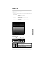
Key to tables
B3.03
Nominal freq.
MENU
VICB
25.00
... 50.00 ... 300.0 Hz
Factory settings
Max. value
or Adjusted value
Parameter identification:
Modification by valid access only (1)
Modification if unlocked by access code (2)
Modifiable when stopped (drive locked) (3)
Modifiable parameter
Parameter name
Min. value
Parameter number
B6. Serial Port configuration
In menu B6 "Communication parameters", the minimum configuration for starting Modbus communication is:
- B6.00 "Selection of the communication bus" at 2 "RS232/Gateway"
- B6.01 "Select remote" at:
1 "Line, Gateway" if the command comes from a PLC via Modbus
0 "Terminals" if the PLC is only monitoring the drive
Menu
Name
Access Default value - range
B6.00
Select bus
VICB
0 … no bus
1 … PROFIBUS DP
2 … RS232 / Gateway (19200 bauds)
3 … Gateway (35700 bauds)
No bus
Profibus DP
FIPIO / Modbus / Modbus plus
ENGLISH
To use the Modbus module, select value 2.
B6.01
Select remote
0 … Terminals
1 … Line, Gateway
VCB
Terminals
terminals + bit 11 to 15 of the CMD control word if bit 10 of the
CMD control word = 1
control word (CMD)
Parameter B6.01 defines whether remote commands (Start, Stop) should be accepted via the
terminals (logic inputs) or by using the control word (CMD) (bits 0-10) via the communication link.
B6.02
Address
Not used by the interface
129
VCB
0 ... 0 ... 126
ATV68 Configuration
Menu
Name
Access Default value - range
B6.03
BUS fault
VICB
0 … Alarm
1 … Trip
2 … Lock
3 … Deceleration
Alarm
(immediately)
(after the time set with B6.04)
(after the time set with B6.04)
(after the time set with B6.04)
This parameter defines the drive reaction to a communication fault on the bus ATV68-module link.
The effect can be delayed using parameter B6.04 (see B6.33 also).
0 … Alarm
1 … Trip: the drive performs a freewheel stop and generates a fault (the fault relay is tripped).
2 … Lock: the drive performs a freewheel stop and does not generate a fault.
3 … Deceleration: the drive stops the motor in accordance with the deceleration ramp and does
not generate a fault.
For options 2 and 3: the drive restarts automatically if a run command has been enabled.
For option 1: the drive only restarts after the fault has been reset, and a "Basic status" command
and a run command have been issued.
B6.04
Delay B6.03
VCB
0 ... 0.0 ... 3200.0 s
This parameter sets the time delay for the reaction occurring after B6.03.
ON after OFF1,3
VICB
Not authorized
0 … not authorized
1 … authorized
This parameter defines whether another start is possible during deceleration (caused by an OFF1
or OFF3 command).
In the "not authorized" configuration, the drive is "locked" once the motor has come to a complete
stop. The master should write the "Basic status" in the control word (CMD) before restarting.
130
ENGLISH
B6.05
ATV68 Configuration
Menu
Name
Access Default value - range
B6.06
Main reference 1
VICB
0 … not used
1 … Freq.ref.man
2 … Freq.ref.aut
3 … Freq. Correct.
4 … Torque Limit.
5 …PID-ref.
6 … PID-feedback
100% = fmax C3.01
100% = fmax C3.01
100% = fmax C3.01
100% = nom. motor torque
100% = 100%
100% = 100%
Not used
If the desired reference
cannot be selected, it
has already been
assigned.
See D1, etc.
ENGLISH
Main reference 1 can be used as a source for various references, as illustrated in the figure below.
The selection is made by parameter B6.06.
Reference types "Freq.ref.man", " Freq.ref.aut" and "F-ref correction" are standardized in Hz,
100% corresponding to the maximum frequency set using parameter C3.01.
The torque limit references, the PID reference and the PID feedback are standardized directly as
a %.
LOC = Local
REM = Remote
LOC MP = Local motorized potentiometer
Local/Remote is used to select either:
Local: references generated by the "Local" motorized potentiometer issued by the programming terminal
keypad or the terminals (loc. + speed, loc. - speed).
Remote: references issued by the communication link or the terminals (other than 1).
B6.07
B6.08
B6.09
131
Aux. reference 2
Aux. reference 3
Aux. reference 4
VICB
VICB
VICB
Not used
Not used
Not used
ATV68 Configuration
Menu
Name
Access Default value - range
B6.10
Aux. reference 5
VICB
Not used
VCB
Out.freq.sig
B6.11
Actual val.1
0 … not used
1 … f- out (signed)
2 … f- out (unsigned)
3 … Out.current
4 … Torque (signed)
5 … (Torque) (unsigned)
6 … Motor power
7 … Motor voltage
8 … N-out sig (signed)
9 … N-out sig (unsigned)
10 …Int.f-ref
A3.00
A2.03
A2.01
A2.04
11 …Int. T-ref.
A4.13
12 …PID-ref.
13 … PID-feedback
14 …PID-error
15 …AIV
16 …AIC
17 …AI_2
18 …AI_3
19 … DC voltage
C4.00
C4.01
20 …Th. State Mot.
21…Braking Resistor Thermal
22 … Fault number
23 … Drive state
A2.12
A3.12
F3.02
AI.03
24 …Position Low
24 …Position High
A2.13
A2.14
A4.00
A4.02
A4.04
A4.06
A3.02
output not assigned
100% = high speed (C3.01)
100% = high speed (C3.01)
100% = nominal motor current (B3.01)
100% = nominal motor torque (B3.00, B3.04)
100% = nominal motor torque (B3.00, B3.04)
100% = nominal motor power (B3.00)
100% = nominal motor voltage (B3.02) V
100% = high speed in rpm (C3.01 x 60/p) (1)
100% = high speed in rpm (C3.01 x 60/p) (1)
100% = high speed (C3.01). Internal frequency
reference before the ramp and before slip
compensation.
100% = nominal motor torque (B3.00, B3.04)
Torque limit internal reference
100% = 100% (C4.00)
100% = 100% (C4.01)
100% = 100% (C4.02)
100% = 10 V = 4000 hex
100% = 20 mA = 4000 hex
100% = 20 mA = 4000 hex
100% = 20 mA = 4000 hex
100% = 813 V on the ATV68 400 and 500;
1200 V on ATV68 700
Thermal state M
Fault code (see programming manual)
State, alarm or limit (see programming manual)
With this parameter, the information relating to the selected analogue value is assigned to the
AO/AI actual value 1 with adequate standardization. All the actual values can be filtered by the
adjustable "actual value filter".
Note: Assignment of the actual value configures the display values of the "Save" function in the
ATV68SOFT PC software.
(1) where p = number of pairs of poles.
B6.12
Act 1 filt.time
VCB
0.00 ... 0.10 ... 10.00 s
VCB
VCB
VCB
VCB
VCB
n-output sig
0.00 ... 0.10 ... 10.00 s
Out.current
0.00 ... 0.10 ... 10.00 s
Torque
Filter on B6.11
B6.13
B6.14
B6.15
B6.16
B6.17
Aux.-act.val.2
Act 2 filt.time
Aux.-act.val.3
Act 3 filt.time
Aux.-act.val.4
132
ENGLISH
For authorized settings see B6.06.
ATV68 Configuration
Menu
Name
Access Default value - range
B6.18
B6.19
B6.20
Act 4 filt.time
Aux.-act.val.5
Act 5 filt.time
VCB
VCB
VCB
0.00 ... 0.10 ... 10.00 s
Power
0.00 ... 0.10 ... 10.00 s
B6.21
Bit 11 Contr.W
VCB
Not used
For authorized settings see B6.11
0 … not used
ENGLISH
1 … 13 not permitted
14 …Pre-set A
15 …Pre-set B
16 …Pre-set C
17 …Manual (Aut)
18 …Local/remote
19 …2.ramp
20 …User macro 2/1
21 …Not permitted
22 …External trip
23 …EXT-Mot.Trip
24 …Insulation fault
25 …Brake fault
26 …Not permitted
27 …EXT-T limit.
28 …PID active
29 …PID-enable
30 …Speed ctrl.act
31 …Brake open
32 …Mains ON(OFF)
33 …ON lock
34 …Force local
35 …Paramet-locked
36 …FWD (REV.)
See table of preset
references
C1 = Manual reference
As a result, program with E3.02 as well
As a result, program with E2.11 as well
In addition to F6.00
1 = Clockwise field
Parameter B6.21 assigns the digital input commands corresponding to bit 11 of the CMD control
word (configured in the master). For details concerning the function of these commands, refer to
the ATV68 Programming manual. See "Parameter Group D2".
B6.22
B6.23
B6.24
B6.25
Bit 12 Contr.W
Bit 13 Contr.W
Bit 14 Contr.W
Bit 15 Contr.W
For authorized settings see B6.21
133
VCB
VCB
VCB
VCB
Not used
Not used
Not used
Not used
ATV68 Configuration
Menu
Name
Access Default value - range
B6.26
Bit 11 Stat.-W (ETA)
VCB
DI1
Contact closed = "1"
Contact closed = "1"
Contact closed = "1"
Contact closed = "1"
Contact closed = "1"
Contact closed = "1"
Contact closed = "1"
Contact closed = "1"
Contact closed = "1"
Contact closed = "1"
Contact closed = "1"
ENGLISH
0 … not used
1 … Ready
2 … Run
3 … Trip
4 … Ready+Run
5 … Alarm
6 … Generat.oper
7 … Contact ctrl
8 … Local (Remote)
9 … f > f-level
10 …Lift Brake
11 …Output C1
12 …Output C2
13 …Output C3
14 …Output C4
15 …Output L5
16 …Output L6
17 …Thyrist.-ON
18 …DI1 •
19 …DI2
20 …DI3
21 …DI4
22 …DI6_2
23 …DI7_2
24 …DI8_2
25 …DI5_3
26 …DI6_3
27 DI7_3
28 …DI8_3
29 …Manual
30 …User Macro 2
31 …EXT-T limit.
32 …PID active
33 …PID enabled
34 …Speed ctrl.act
Parameter B6.26 assigns bit 11 of the status word.
For a description of functions, see the Programming manual "Menu D4".
Note: Assignment of bits 11 to 15 of the STATUS word (ETA) configures the display values of the
"Save" function in the ATV68SOFT PC software.
B6.27
B6.28
B6.29
B6.30
Bit 12 Stat.-W (ETA)
Bit 13 Stat.-W (ETA)
Bit 14 Stat.-W (ETA)
Bit 15 Stat.-W (ETA)
VCB
VCB
VCB
VCB
DI2
DI3
DI4
DI6_2
For authorized settings for B6.27 to B6.30 see B6.26
134
ATV68 Configuration
D3. Configuration of analogue outputs
The PLC can directly control the drive analogue outputs AO1 and AO2 using control words PZD2 to PZD6, ie.
using communication link references 1 to 5.
Menu
Name
D3.00
AO1-selection
0-14
15
15
15
15
15
20-21
D3.04
Access Default value - range
VCB
see Programming manual
Bus Main reference 1
Bus Aux. reference 2
Bus Aux. reference 3
Bus Aux. reference 4
Bus Aux. reference 5
see Programming manual
AO2_2-selection
not used
—
100% = 16#4000
100% = 16#4000
100% = 16#4000
100% = 16#4000
100% = 16#4000
—
VCB
not used
ENGLISH
Note: For this operating mode, parameters B6.06 to B6.10 (depending on the communication link reference to
be used) should be left on the factory setting ("Not used"), thus leaving communication link references 1 to 5
unassigned. Bit 10 of the CMD control word should be set to 1 by the master ("Control by communication link
OK") so that the module can take account of the communication link references.
135
ATV68 Configuration
D4. Configuration of logic outputs
The PLC can control the drive logic outputs directly using the free bits (bits 11 to 15) of the CMD control word.
Menu
Name
Access Default value - range
D4.00
+24 dig.output
VC
0-19 see Programming manual
20 Bus Cont.W 11.
—
The relay is energized if bit
control word equals 1
The relay is energized if bit
control word equals 1
The relay is energized if bit
control word equals 1
The relay is energized if bit
control word equals 1
The relay is energized if bit
control word equals 1
—
21 Bus Cont.W 12.
22 Bus Cont.W 13.
23 Bus Cont.W 14.
24 Bus Cont.W 15.
25-32 see Programming manual
D4.01
D4.02
D4.03
Relay output 1
Relay output 2_2
Relay output 3_2
+24 V
VCB
VCB
VCB
11 of the CMD
12 of the CMD
13 of the CMD
14 of the CMD
15 of the CMD
Ready+Run
not used
not used
ENGLISH
Note: For this operating mode, parameters B6.21 to B6.25 (depending on the free bit to be used) should be
left on the factory setting ("Not used"), thus leaving bits 11 to 15 of the CMD control word unassigned. Bit 10
of the CMD control word should be set to 1 by the master ("Control by communication link OK") so that the
module can take account of the references assigned to the free bits.
136
ATV68 Diagnostics
B6. Diagnostics for the Serial Port
Menu
Name
B6.31
B6.32
B6.33
B6.34
Slave status
Trans. speed
Watchdog status
Com. PPO Type
B6.35
Bus CMD word
Access Default value - range
VCB
Read only
Read only
Read only
Type 2
Parameters B6.31 to B6.34 are not significant in the case of Modbus.
Read only
Displays the control word (CMD) transmitted by the master in hexadecimal format.
B6.36
B6.37
B6.38
B6.39
B6.40
Bus main ref. 1
Bus aux. ref. 2
Bus aux. ref. 3
Bus aux. ref. 4
Bus aux. ref. 5
B6.41
Bus STATUS word
Read only
Read only
Read only
Read only
Read only
Parameters B6.36 to B6.40 display the references supplied by the ATV68 in hexadecimal format.
Read only
ENGLISH
Displays the status word (ETA) generated by the ATV68 in hexadecimal format.
B6.42
B6.43
B6.44
B6.45
B6.46
Bus actual val.1
Bus actual val.2
Bus actual val.3
Bus actual val.4
Bus actual val.5
Read only
Read only
Read only
Read only
Read only
Parameters B6.42 to B6.46 display the actual values supplied by the ATV68 in hexadecimal
format.
B6.47
STATUS requested
Read only
Displays the CMD control word which is valid internally, generated from CMD control word
commands to the bus and from the terminals, if necessary. The position in the ATV68 status chart
depends on the internal CMD control word. It is displayed in hexadecimal format.
137
ATV68 Diagnostics
Active state
Read only
This parameter indicates the internal drive status conforming to the Profibus status chart.
(This parameter is identical to parameter A3.11).
For more details, see "Cyclic control and monitoring variable" and "ATV68 status chart".
0 … Not Ready ON
1 … Rdy. switch ON
2 … Charge Bus DC
3 … Ready to run
4 … Oper. release
5 … Ramp enable
6 … Ramp release
7 … Run
8 … Flux.
9 … Rel. brake 1
10 …Crane active
11 …JOG1 active
12 …JOG1 pause
13 …OFF1 active
14 …OFF3 active
15 …Close brake
16 …Fr. DC-brake 1
17 …Fr. DC-brake 2
18 …OFF2 active
19 …Lock switching on
20 …Trip
21 …Auto tune
22 …Power test
23 … Rel. brake 2
24 … Rel. brake 3
25 …Heating motor.
26 …Trip condition 1
27 …Trip condition 2
ENGLISH
B6.48
138
ATV68 Diagnostics
Menu
Name
B6.49
B6.50
B6.51
B6.52
B6.53
B6.54
B6.55
B6.56
B6.57
B6.58
B6.59
B6.60
B6.61
B6.62
B6.63
B6.64
Param. Buffer 1
Param. Buffer 2
Param. Buffer 3
Param. Buffer 4
Param. Buffer 5
Param. Buffer 6
Param. Buffer 7
Config. Buffer 1
Config. Buffer 2
Diag. Buffer 1
Diag. Buffer 2
Diag. Buffer 3
Diag. Buffer 4
Diag. Buffer 5
Diag. Buffer 6
Global Control
Access Default value - range
Read only
Read only
Read only
Read only
Read only
Read only
Read only
Read only
Read only
Read only
Read only
Read only
Read only
Read only
Read only
Read only
ENGLISH
Parameters B6.49 to B6.64 are not significant in the case of Modbus.
139
ATV68 Diagnostics
A4. Display reference values
Menu
Name
A4.18
A4.19
A4.20
A4.21
A4.22
Bus Main Reference 1 scaled
Bus Aux. Reference 2 scaled
Bus Aux. Reference 3 scaled
Bus Aux. Reference 4 scaled
Bus Aux. Reference 5 scaled
Access Default value - range
Read only
Read only
Read only
Read only
Read only
Parameters A4.18 to A4.22 display the bus references using the standardized value.
Scaled reference
ENGLISH
Reference transmitted
by the master: 0 to ± 200%
in hexadecimal format
140
ATV68 Diagnostics
ENGLISH
Causes of faults (parameter F3.03 / PNU 823)
Fault Number
Fault Text
Fault Number
Fault Text
0
Loss of +24V
35
AR-Flt. 1.0
1
UI-Flt.1.0
36
Power stage
2
UI-Flt.2.0
37
Int.Com3.0
3
UI-Flt.2.1
38
BU Fault
4
UI-Flt.3.0
39
Frequency error
5
UI-Flt.3.1
40
Overcurrent 2
6
UI-Flt.3.2
41
Card temperature
7
UI-Flt.4.0
42
Power supply fault
8
UI-Flt.4.1
43
Not used
9
UI-Flt.4.2
44
Not used
10
AR-Flt. 3.0
45
Not used
11
AR-Flt. 3.1
46
Not used
12
UI-Flt.5.0
47
Temperature of heatsink 2
13
UI-Flt.6.0
48
AR-Flt. 2.0
14
UI-Flt.7.0
49
Temperature of heatsink 1
15
Int.Com1.0
50
Bus comm. 2
16
Int.Com1.1
51
Undervoltage 1
17
Int.Com1.2
52
Undervoltage 2
18
Int.Com1.3
53
Crane overload
19
Int.Com2.0
54
External trip
20
Int.Com1.4
55
External motor trip
21
Com.card-Flt
56
Isolation Fault
22
Bus comm. 1
57
4/20 mA fault
23
AR-Flt. 3.2
58
Thermistor temperature
exceeded?
24
Not used
59
PTC short-circuit
25
Not used
60
Motor thermal fault
26
Not used
61
Stall prot
27
Not used
62
Mot. overspeed
28
Not used
63
Encoder fault
29
Not used
64
Braking unit trip
30
Protection disabled
65
Thermal fault on the DC bus
charging resistor
31
Not used
66
ON lock
32
Fault log
67
Braking resistor overload
33
Overcurrent 1
68
Process fault
34
Overvoltage
70
Underload
For all additional information on individual errors, see the Programming manual.
141
Example of Use
Configuration of the Modbus master
Application requirement:
• The master controls a drive located at address "1" and at one of the two ends of a Modbus network with the
following characteristics:
- Communication speed = 19,200 bauds
- Parity = None
• The master sends:
- the CMD control word without assignment of the free bits
- the frequency reference
• The master receives:
-
the ETA status word with default assignments of the free bits
the motor frequency
the motor current (actual value 2)
the motor torque (actual value 3)
Description
W1029
CMD control word
W1030
Main reference 1: Frequency reference
W1031
Aux. reference 2: Not used
W1032
Aux. reference 3: Not used
W1033
Aux. reference 4: Not used
W1034
Aux. reference 5: Not used
W5
ETA status word
W6
Actual value 1: Motor frequency
W7
Actual value 2: Motor current
W8
Actual value 3: Motor torque
W9
Actual value 4: Not used
W10
Actual value 5: Not used
ENGLISH
Object
Configuration of the Modbus module for ATV68
The slave address should be set at "1", the communication speed at "19,200 bauds" (factory setting) and the
parity at "none" (factory setting).
Address
Switches
Speed
Parity
Description
12345678 1234
0000001x
xxxx
Module address on the Modbus network = 1.
xxxxxxx1
01xx
Communication speed on the Modbus RTU network = 19,200 bauds (factory setting).
xxxxxxxx
xx01
No parity on the Modbus network (factory setting).
142
Example of Use
ATV68 configuration
The following settings should be applied to the drive itself. To apply these settings from the drive terminal
keypad, parameter F6.02 must equal 0 (Access mode = via keypad). Settings marked with a large dot ‘•’ do
not need to be modified, as these are factory settings:
ENGLISH
B6.00
B6.01
B6.06
B6.07
....
B6.10
B6.11
B6.13
B6.15
B6.17
B6.19
B6.21
....
B6.25
B6.26
B6.27
B6.28
B6.29
B6.30
Select bus
Select remote
Main reference 1
Aux. reference 2
.............
Aux. reference 5
Actual val.1
Aux.-act.val.2
Aux.-act.val.3
Aux.-act.val.4
Aux.-act.val.5
Bit 11 Contr.W
.............
Bit 15 Contr.W
Bit 11 Stat.-W
Bit 12 Stat.-W
Bit 13 Stat.-W
Bit 14 Stat.-W
Bit 15 Stat.-W
= 02 … R232/Gateway
= 01 … Link, Gatew.
= 02 … Freq.ref.aut
= 00 … not used •
...............
= 00 … not used •
= 01 … f- out (signed) •
= 03 … Out.current
= 04 … Torque (signed)
= 00 … not used
= 00 … not used
= 00 … not used •
...............
= 00 … not used •
= 18 … DI1 •
= 19 … DI2 •
= 20 … DI3 •
= 21 … DI4 •
= 22 … DI6_2 •
(19,200 bps)
Control word (CMD)
100% = fmax C3.01
—
...
—
100% = high speed (C3.01)
100% = nominal motor current (B3.01)
100% = nominal motor torque (B3.00, B3.04)
output not assigned
output not assigned
—
...
—
Contact closed = "1"
Contact closed = "1"
Contact closed = "1"
Contact closed = "1"
Contact closed = "1"
Once these settings have been applied, parameter F6.02 should be set at 2 (Access mode = via RS232) so
that the Modbus master can access any parameter via the PKW service.
Address
Drive description
Assigned by
W1029
Bits 00 to 10: CMD control word
Bit 11 to 15: Free bits (not assigned)
W1030
Main link reference = Freq.ref.aut
B6.06
W1031
Aux. reference 2 = Not assigned
B6.07
W1032
Aux. reference 3 = Not assigned
B6.08
W1033
Aux. reference 4 = Not assigned
B6.09
W1034
Aux. reference 5 = Not assigned
B6.10
W5
Bit 0 to 10: ETA status word
Bit 1 to 11: DI1 (default assignment)
Bit 1 to 12: DI2 (default assignment)
Bit 1 to 13: DI3 (default assignment)
Bit 1 to 14: DI4 (default assignment)
Bit 1 to 15: DI6_2 (default assignment)
———
B6.26
B6.27
B6.28
B6.29
B6.30
W6
Main actual value = f- out (signed)
B6.11
W7
Actual value 2 = Out.current
B6.13
W8
Actual value 3 = Torque (signed)
B6.15
W9
Actual value 4 = Not assigned
B6.17
W10
Actual value 5 = Not assigned
B6.19
143
———
B6.21 to B6.25
Example of Use
Exchanges on the bus
Master outputs
• Control PZD1 (W1029) = CMD control word: controls the drive according to the PROFIDRIVE standard
(see ATV68 Control and Monitoring section).
• Control PZD2 (W1030) = Main link reference = Freq.ref.aut as internal value: 100% = fmax C3.01,
irrespective of the setting of C3.01; main link reference = C3.01, in Hz, if W1030 = 16384 = 16#4000. To
determine the numerical value to be applied to the "Freq.ref.aut" reference in PZD2 (W1030), expressed in
Hz, use the following equation:
W1030 =
16384 × Desired value (in Hz)
C3.01 (in Hz)
Example: C3.01 = 50 Hz and you wish to control the motor at 25 Hz. The value to be applied to word W1030
is given by the following equation:
W1030 =
16384 × 25
50
= 8192 = 16#2000
Master inputs
- Link active if W0 = 16#1000
- Link inactive if W0 = 16#0000
• Monitoring PZD1 (W5) = ETA status word: Reads the internal drive status according to the PROFIDRIVE
standard (see ATV68 Control and Monitoring section).
• Monitoring PZD2 (W6) = Main actual value = f- out (signed) as an internal value: 100% = high speed
(C3.01), irrespective of the setting of C3.01; Main actual value = C3.01, in Hz, if W6 = 16384 = 16#4000. To
determine the actual value of the output frequency "f- out (signed)", expressed in Hz, as a function of the
numerical value located in PZD2 (W6), use the following equation:
Actual value (in Hz) =
W6 × C3.01 (in Hz)
16384
Example: C3.01 = 50 Hz and the read value is W6 = 16#2000 = 8192. The actual value of the output frequency
"f- out (signed)", read in word W6, is given by the following equation:
Actual value (in Hz) =
8192 × 50
16384
= 25 Hz
144
ENGLISH
• Module status word (W0): The Modbus master monitors the value of bit 12 (Subnet Status) of word W0 to
determine whether the ATV68-module link is working or not (see ATV68 Control and Monitoring section).
If W0: 12 = 1, this means that the input data located in the module memory are updated periodically. If W0:
12 = 0, the values of the input data should not be taken into account by the Modbus master, since they have
not been refreshed.
Example of Use
• Monitoring PZD3 (W7) = Actual value 2 = Out.current as an internal value: 100% = nominal motor
current (B3.01), irrespective of the setting of B3.01; Out.current = B3.01, in A, if W7 = 16384 = 16#4000. To
determine the actual value of the output current "Out.current", expressed in A, as a function of the numerical
value read in W7, use the following equation:
Actual value (in A) =
W7 × B3.01 (in A)
16384
Example: 110 kW drive, B3.01 = 156.3 A and the read value is W7 = 16#2000 = 8192. The actual value of the
output current "Out.current", read in word W7, is given by the following equation:
Actual value (in A) =
8192 × 156.3
16384
= 78.15 A
• Monitoring PZD4 (W8) = Actual value 3 = Torque (signed) as an internal value: 100% = nominal motor
current Tn; Torque (signed) = 100% if W8 = 16384 = 16#4000. To determine the actual value of the torque
"Torque (signed)", expressed as a % of Tn, as a function of the numerical value read in W8, use the following
equation:
Actual value (as a % of Tn) =
W8 × 100
16384
Example: The read value is W8 = 16#2000 = 8192. The actual value of the torque "Torque (signed)", read in
word W8, is given by the following equation:
ENGLISH
Actual value (as a % of Tn) =
145
8192 × 100
16384
= 50% of Tn
List of Parameters
Voltage:
Reference:
Serial no:
Code:
Customer/Company:
Supplier/Company:
Delivery date:
Commissioning date:
Parameter adjustments
Para.
No.
Description
PNU Code Type D Standardization
Min.
Max.
Trip
A 1 00 Configuration/
Settings
971
A 1 01 Device mode 1
A 1 02 Control mode
Value
A1 Display
VB
O2
---
0
1
(0) Begin 0->1
100
O2
---
---
---
(5) Stop
891
O2
---
---
---
(0) Remote
A 1 03 Device mode 2
101
O2
---
---
---
0
A 1 04 LED state
102
O2
---
---
---
(1) READY
A 2 00 Speed
110
N2
16384.0
---
---
+0 rpm
A 2 01 Torque
111
N2
Motor m nom.
(B3.00/B3.04*60/2/pi)
---
---
+0 Nm
A 2 02 Motor load
112
N2
100.0
---
---
0%
A 2 03 Motor current
113
N2
Device I nom (A3.06) ---
---
0.0 A
A 2 04 Mech. power
114
N2
Motor P nom. (B3.00) ---
---
+0.0 kW
A 2 05 Apparent power 115
N2
SN (B3.01*B3.02)
---
---
0.0 kVA
A 2 06 Motor voltage
116
N2
812.81875
(1200.0 at 690 V)
---
---
3V
A 2 07 Slip frequency
117
N2
163.84
---
---
0.0 Hz
A 2 08 Linear speed
118
NF
---
---
---
+0.00 m/min
119
NF
---
---
---
+0.00 rpm
ENGLISH
A2 Display Motor value
[v]
A 2 09 Speed of
rotation [n]
A 2 10 Process scaling
120
VCB
NF
---
-10,000 +10,000 +1,000
A 2 11 Process scaling
121
VCB
NF
---
-10,000 +10,000 +1,000
N2
163.84
---
A3 Display Drive value
A 3 00 Output freq.
130
---
+0.00 Hz
146
List of Parameters
Para.
No.
Description
PNU Code Type D Standardization
Min.
Max.
Trip
A 3 01 Drive load
131
N2
100.0
---
---
0%
A 3 02 DC-voltage
132
N2
812.81875 (1200.0 at --690 V)
---
604 V
A 3 03 Heatsink
temperature
133
N2
0.01
---
---
+32 ° C
A 3 04 Switching
frequency
134
O2
---
---
---
(0) 2.5 kHz
A 3 05 Drive reference
802
OS4[4] ---
---
---
ATV68iiiii
A 3 06 Nom. drive
current ‘C’
136
NF
---
---
208 A
---
A 3 07 Hardware vers.
803
OS4[4] ---
---
---
8844110.01
A 3 08 Software-type
801
OS4[2] ---
---
---
PSR3_A1
A 3 09 Software vers.
800
OS4[2] ---
---
---
8782400.04/04
A 3 10 Serial No.
804
OS4[4] ---
---
---
123456
A 3 11 Drive ETA
status word
(ZSW)
135
O2
---
---
---
(1)
RdyswitchON
ENGLISH
A4 Display drive references
A 4 00 AIV 0..10V
140
N2
100.0
---
---
+0.5%
A 4 01 AIV scaled
141
N2
163.84 (100.0)
---
---
+0.25 Hz
A 4 02 AIC 0(4)..20mA 142
N2
100.0
---
---
+0.0%
A 4 03 AIC scaled
N2
163.84 (100.0)
---
---
+0.00 Hz
143
A 4 04 AI_2 0(4)..20mA 144
N2
100.0
---
---
+0.0%
A 4 05 AI_2 scaled
N2
163.84 (100.0)
---
---
+0.01 Hz
145
A 4 06 AI_3 0(4)..20mA 146
N2
100.0
---
---
+0.0%
A 4 07 AI_3 scaled
147
N2
163.84 (100.0)
---
---
+0.01 Hz
A 4 08 Preset reference 148
N2
163.84 (100.0)
---
---
+0.00 Hz
A 4 09 Local reference
149
N2
163.84 (100.0)
---
---
+0.00 Hz
A 4 10 Remote
reference
150
N2
163.84 (100.0)
---
---
+0.01 Hz
A 4 11 Freq. before
ramp
151
N2
163.84
---
---
+0.00 Hz
A 4 12 Freq. after ramp 152
N2
163.84
---
---
+0.00 Hz
A 4 13 Max. torque
reference
153
N2
100.0
---
---
200.0%
A 4 14 Digital input X1
160
O2
---
---
---
0
A 4 15 Digital input X2
161
O2
---
---
---
1
A 4 16 Digital input X3
162
O2
---
---
---
0
147
Value
List of Parameters
Para.
No.
Description
PNU Code Type D Standardization
Min.
Max.
Trip
A 4 17 BUS CTRL word 154
(STW)
V2
---
---
---
0406 hex
A 4 18 Main reference
1
155
N2
163.84 (100.0)
---
---
+0.00 Hz
A 4 19 Aux. reference 2 156
N2
163.84 (100.0)
---
---
+0.00 Hz
A 4 20 Aux. reference 3 157
N2
163.84 (100.0)
---
---
+0.00 Hz
A 4 21 Aux. reference 4 158
N2
163.84 (100.0)
---
---
+0.00 Hz
A 4 22 Aux. reference 5 159
N2
163.84 (100.0)
---
---
+0.00 Hz
Value
A5 Time / kWh
A 5 00 Motor operating
hours
810
NF
---
---
---
0.00 hr
A 5 01 Drive operating
hours
812
NF
---
---
---
0.67 hr
A 5 02 kWh metre
[MWh]
811
NF
---
---
---
0.000 MWh
A6 Display configuration
A 6 00 Select zone 1
190
VCB
O2
---
0
19
(0) output freq.
A 6 01 Select zone 2
191
VCB
O2
---
0
18
(11) Int. f-ref
A 6 02 Select zone 3
192
VCB
O2
---
0
19
(5) Motor
current
A 6 03 Display Limits
193
VCB
O2
---
0
1
(0) no display
850
VCB
O2
---
0
3
(1) English
B 1 00 Language
Selection
ENGLISH
B1 Choice of language
B2 Selection of an application macro
B 2 00 Display macro
864
O2
---
---
---
(0) Conveyor
B 2 01 Store USER
Macro 1
861
VCB
O2
---
0
1
(0) Begin 0->1
B 2 02 Store USER
Macro 2
862
VCB
O2
---
0
1
(0) Begin 0->1
B 2 03 Selection of the
application
macro
860
VICB O2
---
0
11
(0) Conveyor
B 2 04 Multi
configuration/
motor
863
VCB
O2
---
0
2
(0) not active
B3 Motor data
B 3 00 Nominal power
10
VICB NF
---
0.0
2500.0
132.0 kW
B 3 01 Nominal current 11
VICB NF
---
0.0
2500.0
239.0 A
B 3 02 Nominal voltage 12
VICB NF
---
0
1000
400 V
B 3 03 Nominal
frequency
VICB NF
---
25
300
50 Hz
13
148
List of Parameters
Para.
No.
Description
PNU Code Type D Standardization
B 3 04 Nominal speed
14
VICB NF
B 3 05 Line voltage
16
VICB O2
---
Min.
Max.
Trip
0
18000
1488 rpm
0
3
(0) 400V; 50/
60Hz
B 3 06 Overmodulation 17
VICB O2
0
1
(0) not active
B 3 07 Motor output
filter
15
VICB O2
---
0
1
(0) not used
870
B4 Autotuning
B 4 00 Autotuning
VICB O2
---
0
1
(0) Begin 0->1
B 4 01 Rotor coefficient 20
VICB NF
---
0
999999
3611
B 4 02 Rotor time
Const.
21
VICB NF
---
0.000
4.000
1.246 s
B 4 03 Stator Resist.
22
VICB NF
---
0.00
20000.0 15.24 mOhm
0
B 4 04 Fluxing current
23
VICB NF
B 4 05 Autotuning
current
24
N2
---
0.0
2500.0
72.7 A
Inom device (A3.06)
---
---
+0.0 A
(0) no bus
ENGLISH
B6 Communication parameter
B 6 00 Select bus
928
VICB O2
---
0
2
B 6 01 Select remote
701
VICB O2
---
0
1
(0) terminals
B 6 02 Address
918
VCB
---
0
126
Not used by the
interface (0)
O2
B 6 03 BUS fault
703
VCB
O2
---
0
3
(0) Alarm
B 6 04 Delay B6.03
704
VCB
T2
0.1
0.0
3200.0
0.0 s
B 6 05 ON after OFF1,3 705
VICB O2
---
0
1
(0) not
authorized
B 6 06 Main reference 1 880
VICB O2
---
0
6
(0) not used
B 6 07 Aux. reference 2 881
VICB O2
---
0
6
(0) not used
B 6 08 Aux. reference 3 882
VICB O2
---
0
6
(0) not used
B 6 09 Aux. reference 4 883
VICB O2
---
0
6
(0) not used
B 6 10 Aux. reference 5 884
VICB O2
---
0
6
(0) not used
B 6 11 Actual val.1
VCB
---
0
19
(1) out.freq.sig
0.10 s
885
O2
B 6 12 Act 1 filt.time
709
VCB
T2
0.005
0.00
10.00
B 6 13 Aux.-act.val.2
886
VCB
O2
---
0
19
(8) n-output sig
B 6 14 Act 2 filt.time
711
VCB
T2
0.005
0.00
10.00
0.10 s
B 6 15 Aux.-act.val.3
887
VCB
O2
---
0
19
(3) Output
current
0.10 s
B 6 16 Act 3 filt.time
713
VCB
T2
0.005
0.00
10.00
B 6 17 Aux.-act.val.4
888
VCB
O2
---
0
19
(4) Torque
B 6 18 Act 4 filt.time
715
VCB
T2
0.005
0.00
10.00
0.10 s
149
Value
List of Parameters
Description
PNU Code Type D Standardization
Min.
Max.
Trip
B 6 19 Aux.-act.val.5
889
VCB
O2
---
0
19
(6) Power
B 6 20 Act 5 filt.time
717
VCB
T2
0.005
0.00
10.00
0.10 s
B 6 21 Bit 11 Contr.W
933
VCB
O2
---
0
36
(0) not used
B 6 22 Bit 12 Contr.W
934
VCB
O2
---
0
36
(0) not used
B 6 23 Bit 13 Contr.W
935
VCB
O2
---
0
36
(0) not used
B 6 24 Bit 14 Contr.W
936
VCB
O2
---
0
36
(0) not used
B 6 25 Bit 15 Contr.W
937
VCB
O2
---
0
36
(0) not used
B 6 26 Bit 11 Stat.-W
939
VCB
O2
---
0
34
(18) DI1
B 6 27 Bit 12 Stat.-W
940
VCB
O2
---
0
34
(19) DI2
B 6 28 Bit 13 Stat.-W
941
VCB
O2
---
0
34
(20) DI3
B 6 29 Bit 14 Stat.-W
942
VCB
O2
---
0
34
(21) DI4
B 6 30 Bit 15 Stat.-W
943
VCB
O2
---
0
34
(22) DI6_2
B 6 31 Slave status
728
O2
---
---
---
Not used by the
interface (3)
ATV68 missing
B 6 32 Trans. speed
963
O2
---
---
---
Not used by the
interface (0) 12
MBaud
B 6 33 Watchdog
status
730
---
---
---
Not used by the
interface (0) not
connected
---
0
3
Not used by the
interface (1)
Type 2
B 6 34 Com. PPO Type 731
O2
VCB
O2
B 6 35 Contr.W on BUS 967
V2
---
---
---
0000 hex
B 6 36 Bus main ref. 1
733
O2
---
---
---
0000 hex
B 6 37 Bus aux. ref. 2
734
O2
---
---
---
0000 hex
B 6 38 Bus aux. ref. 3
735
O2
---
---
---
0000 hex
B 6 39 Bus aux. ref. 4
736
O2
---
---
---
0000 hex
B 6 40 Bus aux. ref. 5
737
O2
---
---
---
0000 hex
B 6 41 Bus STATUS
word
968
V2
---
---
---
0031 hex
B 6 42 Bus actual val.1 739
O2
---
---
---
0000 hex
B 6 43 Bus actual val.2 740
O2
---
---
---
0000 hex
B 6 44 Bus actual val.3 741
O2
---
---
---
0000 hex
B 6 45 Bus actual val.4 742
O2
---
---
---
0000 hex
Value
ENGLISH
Para.
No.
150
List of Parameters
ENGLISH
Para.
No.
Description
PNU Code Type D Standardization
Min.
Max.
Trip
B 6 46 Bus actual val.5 743
O2
---
---
---
0000 hex
B 6 47 STATUS
requested
760
V2
---
---
---
0406 hex
B 6 48 Active state
761
O2
---
---
---
(1)
Rdy.switchON
B 6 49 Param. Buffer 1
744
O2
---
---
---
Not used by the
interface (0000
hex)
B 6 50 Param. Buffer 2
745
O2
---
---
---
Same (0000 hex)
B 6 51 Param. Buffer 3
746
O2
---
---
---
Same (0000 hex)
B 6 52 Param. Buffer 4
747
O2
---
---
---
Same (0000 hex)
B 6 53 Param. Buffer 5
748
O2
---
---
---
Same (0000 hex)
B 6 54 Param. Buffer 6
749
O2
---
---
---
Same (0000 hex)
B 6 55 Param. Buffer 7
750
O2
---
---
---
Same (0000 hex)
B 6 56 Config. Buffer 1
751
O2
---
---
---
Same (0000 hex)
B 6 57 Config. Buffer 2
752
O2
---
---
---
Same (0000 hex)
B 6 58 Diag. Buffer 1
753
O2
---
---
---
Same (0000 hex)
B 6 59 Diag. Buffer 2
754
O2
---
---
---
Same (0000 hex)
B 6 60 Diag. Buffer 3
755
O2
---
---
---
Same (0000 hex)
B 6 61 Diag. Buffer 4
756
O2
---
---
---
Same (0000 hex)
B 6 62 Diag. Buffer 5
757
O2
---
---
---
Same (0000 hex)
B 6 63 Diag. Buffer 6
758
O2
---
---
---
Same (0000 hex)
B 6 64 Global Control
759
O2
---
---
---
Same (0000 hex)
C1 General functions
C 1 00 Inc.start Tor.
300
VCB
N2
100.0
0
30
1%
C 1 01 Inc.steady Tor.
301
VCB
N2
163.84
5
45
10 Hz
C 1 02 Stop mode
302
VCB
O2
---
0
2
(1) Decel. ramp
C 1 03 Braking mode
316
VICB O2
---
0
4
(0) no brake
oper.
5
(0) not used
C 1 04 Preset.ref.
303
VICB O2
---
0
C 1 05 Preset.ref. 1
304
VCB
N2
163.84 (100.0)
-327.68 +327.67 +0.00 Hz
C 1 06 Preset.ref. 2
305
VCB
N2
163.84 (100.0)
-327.68 +327.67 +0.00 Hz
C 1 07 Preset.ref. 3
306
VCB
N2
163.84 (100.0)
-327.68 +327.67 +0.00 Hz
C 1 08 Preset.ref. 4
307
VCB
N2
163.84 (100.0)
-327.68 +327.67 +0.00 Hz
C 1 09 Preset.ref. 5
308
VCB
N2
163.84 (100.0)
-327.68 +327.67 +0.00 Hz
151
Value
List of Parameters
Para.
No.
Description
PNU Code Type D Standardization
Min.
Max.
Trip
C 1 10 Preset.ref. 6
309
VCB
N2
163.84 (100.0)
-327.68 +327.67 +0.00 Hz
C 1 11 Preset.ref. 7
310
VCB
N2
163.84 (100.0)
-327.68 +327.67 +0.00 Hz
C 1 12 Preset.ref. 8
311
VCB
N2
163.84 (100.0)
-327.68 +327.67 +0.00 Hz
C 1 13 Jog-Frequency
312
VCB
N2
163.84
-10.00
+10.00
+0.00 Hz
C 1 14 Economy mode
313
VCB
O2
---
0
4
(0) not active
Value
C2 Ramps
C 2 00 Accel. ramp 1
320
VCB
T2
0.1
0.0
3200.0
5.0 s
C 2 01 Decel. ramp 1
321
VCB
T2
0.1
0.0
3200.0
5.0 s
C 2 02 Accel. ramp 2
322
VCB
T2
0.1
0.0
3200.0
20.1 s
C 2 03 Decel. ramp 2
323
VCB
T2
0.1
0.0
3200.0
20.1 s
C 2 04 S-ramp
324
VCB
O2
---
0
3
(0) no S ramp
C 2 05 S-ramp mode
325
VCB
O2
---
0
1
(0) Begin + End
C 3 00 Min. frequency
330
VCB
N2
163.84
0.00
300.00
0.00 Hz
C 3 01 Max. frequency
331
VCB
N2
163.84
25.00
300.00
50.00 Hz
C 3 02 Dir. Enable
332
VICB O2
---
0
2
(2) FW/RV
active
C 4 04 PID enable
344
VICB O2
---
0
1
(0) no
C 4 05 Prop. gain (kp)
345
VCB
N2
1600.0
0.0
3199.9
0.0%
C 4 06 Integ.time (Tn)
346
VCB
T2
0.01
0.00
320.00
0.00 s
C 4 07 Deriv.time (Tv)
347
VCB
T2
0.01
0.00
320.00
0.00 s
C 4 08 Ref. acc. ramp
348
VCB
T2
0.1
0.0
3200.0
0.0 s
C 4 09 Ref. dec. ramp
349
VCB
T2
0.1
0.0
3200.0
0.0 s
C 4 10 Out. scaling -
351
VCB
N2
163.84
-300.00 +300.00 0.00 Hz
C 4 11 Out. scaling +
352
VCB
N2
163.84
-300.00 +300.00 0.00 Hz
C3 Speed range
ENGLISH
C4 PID configuration
C6 Special functions
C 6 00 Contactor cont.
380
VICB O2
---
0
1
C 6 01 Crane-function
381
VICB O2
---
0
2
(0) not active
(0) not active
C 6 02 Release freq.
382
VCB
N2
163.84
0.0
20.0
1.7 Hz
C 6 03 Release time
386
VCB
T2
0.005
0.0
160.0
0.3 s
C 6 04 Engage freq.
387
VCB
N2
163.84
0.0
20.0
1.5 Hz
C 6 05 Engage time
388
VCB
T2
0.005
0.0
160.0
0.3 s
152
List of Parameters
Para.
No.
Description
PNU Code Type D Standardization
Min.
Max.
Trip
C 6 06 DC braking time 383
VCB
T2
0.005
0.0
160.0
0.3 s
C 6 07 DC braking curr
384
VCB
N2
100.0
0
150
100%
C 6 08 Restart delay
389
VCB
T2
0.005
0.0
10.0
0.7 s
C 6 09 Hoist mode
390
VCB
O2
---
0
1
(0) no
C 6 10 Max (n)error.
385
VCB
N2
16384.0
0
300
5
D 1 00 AIV-selection
400
VICB O2
---
0
6
(0) not used
D 1 01 AIV-value 0%
401
VCB
N2
163.84 (100.0)
-327.68 +327.67 +0.01 Hz
D 1 02 AIV-value 100% 402
VCB
N2
163.84 (100.0)
-327.68 +327.67 +50.01 Hz
D 1 03 AIV-filter time
403
VCB
T2
0.005
0.00
10.00
0.05 s
D 1 04 AIC-selection
404
VICB O2
---
0
6
(2) Freq.ref.aut
D 1 05 AIC-level
405
VCB
O2
---
0
1
(1) 4-20mA
D 1 06 AIC-value 0%
406
VCB
N2
163.84 (100.0)
-327.68 +327.67 +0.00 Hz
D 1 07 AIC-value 100% 407
VCB
N2
163.84 (100.0)
-327.68 +327.67 +50.00 Hz
D 1 08 AIC-filter time
408
VCB
T2
0.005
0.00
10.00
0.05 s
D 1 09 AI_2-selection
409
VICB O2
---
0
6
(0) not used
D 1 10 AI_2-level
410
VCB
O2
---
0
1
(0) 0-20mA
D 1 11 AI_2-value 0%
411
VCB
N2
163.84 (100.0)
-327.68 +327.67 +0.01 Hz
D 1 12 AI_2-value
100%
412
VCB
N2
163.84 (100.0)
-327.68 +327.67 +50.01 Hz
T2
ENGLISH
D1 Analogue inputs
D 1 13 AI_2-filter time
413
VCB
0.005
0.00
10.00
0.05 s
D 1 14 AI_3-selection
414
VICB O2
---
0
6
(0) not used
D 1 15 AI_3-level
415
VCB
O2
---
0
1
(0) 0-20mA
D 1 16 AI_3-value 0%
416
VCB
N2
163.84 (100.0)
-327.68 +327.67 +0.01 Hz
D 1 17 AI_3-value
100%
417
VCB
N2
163.84 (100.0)
-327.68 +327.67 +50.01 Hz
D 1 18 AI_3-filter time
418
VCB
T2
0.005
0.00
10.00
0.05 s
D 2 00 DI1-selection
441
VICB O2
---
0
35
(1) Begin FWD
D 2 01 DI2-selection
442
VICB O2
---
0
35
(2) Begin REV
D 2 02 DI3-selection
443
VICB O2
---
0
35
(19) 2nd ramp
D 2 03 DI4-selection
444
VICB O2
---
0
35
(26) EXT
reinitial.
D 2 04 DI6_2-selection
445
VICB O2
---
0
35
(0) not used
D 2 05 DI7_2-selection
446
VICB O2
---
0
35
(0) not used
D2 Logic inputs
153
Value
List of Parameters
Para.
No.
Description
PNU Code Type D Standardization
Min.
Max.
Trip
D 2 06 DI8_2-selection
447
VICB O2
---
0
35
(0) not used
D 2 07 DI5_3-selection
448
VICB O2
---
0
35
(0) not used
D 2 08 DI6_3-selection
449
VICB O2
---
0
35
(0) not used
D 2 09 DI7_3-selection
465
VICB O2
---
0
35
(0) not used
D 2 10 DI8_3-selection
466
VICB O2
---
0
35
(0) not used
215
VCB
---
0
21
(2) out.freq.sig
mssg
Value
D 3 00 AO1-selection
O2
D 3 01 AO1_level
451
VCB
O2
---
0
1
(1) 4-20mA
D 3 02 AO1-min. value
452
VCB
N2
100.0
-200
+200
+0%
D 3 03 AO1-max. value 453
VCB
N2
100.0
-200
+200
+100%
D 3 04 AO2_2selection
VCB
O2
---
0
21
(0) not used
216
D 3 05 A02_2-level
455
VCB
O2
---
0
1
(1) 4-20mA
D 3 06 AO2_2min.value
456
VCB
N2
100.0
-200
+200
+0%
D 3 07 AO2_2max.value
457
VCB
N2
100.0
-200
+200
+100%
D 3 08 AO2_3selection
217
VCB
O2
---
0
21
(0) not used
D 3 09 AO2_3-level
459
VCB
O2
---
0
1
(1) 4-20mA
D 3 10 AO2_3min.value
460
VCB
N2
100.0
-200
+200
+0%
D 3 11 AO2_3max.value
461
VCB
N2
100.0
-200
+200
+100%
D 4 00 +24 dig.output
200
VCB
O2
---
0
31
(25) ON (+24V)
D 4 01 Output relay 1
201
VCB
O2
---
0
31
(4) Ready +
Run
D 4 02 Output relay 2_2 202
VCB
O2
---
0
31
(0) not used
D 4 03 Output relay 3_2 203
VCB
O2
---
0
31
(0) not used
D 4 04 Output relay 2_3 204
VCB
O2
---
0
31
(0) not used
D 4 05 Output relay 3_3 205
VCB
O2
---
0
31
(0) not used
D 4 06 f-Level ON
476
VCB
N2
163.84
0.00
300.00
5.01 Hz
D 4 07 f-Level OFF
477
VCB
N2
163.84
0.00
300.00
2.01 Hz
D 4 08 Hyst. f =f-ref
478
VCB
N2
163.84
0.1
10.0
0.5 Hz
D 5 00 Encoder/
Slipcom
570
VICB O2
---
0
2
(0) no encoder
D 5 01 Dyn.
SlipCompens
581
VCB
---
0
2
(0) low
ENGLISH
D3 Analogue outputs
D4 Logic outputs
D5 Encoder configuration
O2
154
List of Parameters
Para.
No.
Description
PNU Code Type D Standardization
Min.
Max.
2
Trip
D 5 02 Speed ctrl.act
571
VICB O2
---
0
D 5 03 Pulse/rotation
572
VICB N2
16384.0
-10000 +10000
+1024
(0) not active
D 5 04 Speed ctrl. Kp
573
VCB
N2
1638.4
0.0
200.0
0.0
D 5 05 Speed ctrl. Tn
574
VCB
T2
0.005
0.00
10.00
0.00 s
D 5 06 Speed ctrl.Stat
575
VCB
N2
1638.4
0.0
20.0
0.0%
0.00 s
D 5 07 ActVal.PT1 time 576
VCB
T2
0.005
0.00
10.00
D 5 08 ActVal.DT1 time 577
VCB
T2
0.005
0.00
1.00
0.00 s
D 5 09 SetVal.PT1 time 578
VCB
T2
0.005
0.00
10.00
0.00 s
D 5 10 Ref-Val.offer.D
579
VCB
N2
1638.4
0.0
10.0
0.0
D 5 11 R-Val.offer.PT1
580
VCB
T2
0.005
0.00
1.00
0.00 s
(0) Ref. freq.
D6 Electronic potentiometer
ENGLISH
D 6 00 Loc.MP select.
VICB O2
---
0
1
D 6 01 Loc.MP min. val. 481
480
VCB
N2
163.84 (100.0)
+0.00
+327.67 +0.00 Hz
D 6 02 Loc.MP max.
val.
VCB
N2
163.84 (100.0)
+0.00
+327.67 +50.00 Hz
482
D 6 03 Loc.MP acc.time 483
VCB
T2
0.1
0.0
3200.0
10.0 s
D 6 04 Loc.MP
dec.time
484
VCB
T2
0.1
0.0
3200.0
10.0 s
D 6 05 Loc.ref.storage
485
VCB
O2
---
0
1
(0) not active
D 6 06 Rem.MP select. 486
VICB O2
---
0
5
(0) not used
D 6 07 Rem.MP
min.val.
487
VCB
N2
163.84 (100.0)
-327.68 +327.67 +0.01 Hz
D 6 08 Rem.MP
max.val.
488
VCB
N2
163.84 (100.0)
-327.68 +327.67 +50.01 Hz
D 6 09 Rem.MP
acc.time
489
VCB
T2
0.1
0.0
3200.0
10.0 s
D 6 10 Rem.MP
dec.time
490
VCB
T2
0.1
0.0
3200.0
10.0 s
D 6 11 Rem.MP control 492
VCB
O2
---
0
1
(1) terminals
D 6 12 Rem.ref.storage 491
VCB
O2
---
0
1
(0) not active
500
VCB
N2
100.0
10
150
150%
E 1 01 Torque max.val. 501
VCB
N2
100.0
10
200
200%
(0) not active
E1 Drive overload
E 1 00 Curr. max.val
E2 Motor protection
E 2 00 Thermistor input 522
VCB O2
---
0
3
E 2 01 Thermist.protec
511
VCB
O2
---
0
1
(0) trip
E 2 02 I max at 0 Hz
512
VCB
N2
100.0
0
150
50%
E 2 03 I max at f nom.
513
VCB
N2
100.0
30
150
100%
155
Value
List of Parameters
Para.
No.
Description
E 2 04 Therm.f-limit
PNU Code Type D Standardization
Min.
Max.
Trip
514
VCB
N2
163.84
0
300
30 Hz
E 2 05 Motor-tme const 515
VCB
T2
0.1067 (6.4s/60)
0
3200
5 min
E 2 06 Stalling time
516
VCB
T2
0.1
0
160
60 s
E 2 07 Stalling frequ.
517
VCB
N2
163.84
0
20
5 Hz
E 2 08 Stalling curr.
518
VCB
N2
100.0
0
150
80%
E 2 09 n. Prot.
519
VCB
O2
---
0
2
(1) trip
E 2 10 N max motor
520
VCB
N2
16384.0
200
18000
3200 rpm
E 2 11 EXT-mot.trip
523
VCB
O2
---
0
6
(0) not active
E 2 12 M Delay f.
524
VCB
T2
0.005
0.0
160.0
1.0 s
Value
E 3 00 Autorestart
530
VCB
O2
---
0
1
(0) not active
E 3 01 Loss of 4-20mA
531
VCB
O2
---
0
3
(0) not active
E 3 02 External trip
536
VCB
O2
---
0
6
(0) not active
E 3 03 Delay f.
537
VCB
T2
0.005
0.0
160.0
0.0 s
E 3 04 Insulation Fault
538
VCB
O2
---
0
6
(0) not active
E 3 05 Insul. Delay f.
539
VCB
T2
0.005
0.0
160.0
10.0 s
E 3 06 Trip of ext. BU
525
VCB
O2
---
0
6
(2)
N.O.rdy+run
E 3 07 Brake delay f.
526
VCB
T2
0.005
0.0
160.0
5.0 s
E 3 08 Undervoltage
534
VCB
O2
---
0
2
(0) no trip
E 3 09 Undervoltge
delay
544
VCB
T2
0.005
0.0
20.0
2.0 s
E 3 10 Local reset
535
VCB
O2
---
0
1
(1) active
E 4 00 Loc/Rem ref.
540
VICB O2
---
0
2
(0) Local/
remote
E 4 01 Operate-Mode
541
VICB O2
---
0
2
(0) Local/
remote
E 4 02 Loc/Rem-switch 543
VICB O2
---
0
1
(0) keypad
E 4 03 Ctrl.mode local
545
VICB O2
---
0
1
(0) keypad
E 4 04 Local STOP
542
VCB
---
0
1
(0) Loc.
feedback only
ENGLISH
E3 Fault configuration
E4 Control configuration
O2
E5 Skip frequency
E 5 00 Skip frequency
550
VCB
N2
163.84
5.00
300.00
5.00 Hz
E 5 01 Hysteresis
551
VCB
N2
163.84
0.00
4.00
0.00 Hz
E6 Switching frequency
156
List of Parameters
Para.
No.
Description
PNU Code Type D Standardization
Min.
Max.
Trip
E 6 00 Min.pulse freq.
560
VCB
O2
---
0
2 (1)
(0) 2.5 kHz
E 6 01 Max.switch.freq
561
VCB
O2
---
0
2 (1)
(0) 2.5 kHz
(0) Begin 0->1
ENGLISH
F1 Contextual help on a fault
F 1 00 Test power part
871
VICB O2
---
0
1
F 1 01 Test-cont.part
872
VICB O2
---
0
1
(0) Begin 0->1
F 1 02 DC Bus
Overvoltage
602
O2
---
0
4
(0) text
F 1 03 DC Bus
Undervoltage
603
O2
---
0
3
(0) text
F 1 04 Overcurrent
604
O2
---
0
3
(0) text
F 1 05 External trip
605
O2
---
0
3
(0) text
F 1 06 4mA trip
606
O2
---
0
1
(0) text
F 1 07 Motor Temp.
(Thermistor)>>
607
O2
---
0
3
(0) text
F 1 08 PTC shortcircuit
608
O2
---
0
2
(0) text
F 1 09 External motor
fault
609
O2
---
0
2
(0) text
F 1 10 Motor thermal
fault
610
O2
---
0
3
(0) text
F 1 11 Shaft stall
611
O2
---
0
3
(0) text
F 1 12 Insulation fault
623
O2
---
0
2
(0) text
F 1 13 Braking unit trip
627
O2
---
0
2
(0) text
F 1 14 Overspeed
612
O2
---
0
1
(0) text
F 1 15 Encoder fault
624
O2
---
0
2
(0) text
F 1 16 Heatsink
overheating
613
O2
---
0
3
(0) text
(0) text
F 1 17 T° C. card>>
614
O2
---
0
1
F 1 18 Power stage
615
O2
---
0
2
(0) text
F 1 19 Fault on
daughter board
616
O2
---
0
2
(0) text
F 1 20 Internal fault
617
O2
---
0
2
(0) text
F 1 21 Fault on control
card
618
O2
---
0
0
(0) text
F 1 22 Crane overload
619
O2
---
0
2
(0) text
F 1 23 Bus comm. 1
620
O2
---
0
3
(0) text
F 1 24 Bus comm. 2
621
O2
---
0
2
(0) text
F 1 25 Communication
option fault
622
O2
---
0
2
(0) text
157
Value
List of Parameters
Para.
No.
Description
PNU Code Type D Standardization
Min.
Max.
Trip
F 1 26 T° fault on the
629
DC bus charging
resistor
O2
---
0
2
(0) text
F 1 27 ON lock
628
O2
---
0
4
(0) text
F 1 28 Loss of 24V
625
O2
---
0
2
(0) text
F 1 29 Fault log
626
O2
---
0
2
(0) text
F 2 00 Ret.fact.appli.
630
VICB O2
---
0
1
(0) Begin 0->1
F 2 01 Ret.fact.motor
631
VICB O2
---
0
1
(0) Begin 0->1
N2
16384.0
---
---
5
O2
---
0
15
(0) last event
Value
F2 Factory settings
F 3 00 Fault code
952
F 3 01 Review
821
F 3 02 Trip number
822
N2
16384.0
---
---
4
F 3 03 Fault
823
O2
---
---
---
(58) Mot.temp
>
F 3 04 Operat.hours
FI A
824
NF
---
---
---
380.09 hr
F 3 05 F-out
825
N2
163.84
---
---
+42.00 Hz
F 3 06 Speed
835
N2
16384.0
---
---
+1258 rpm
F 3 07 Motor current
826
N2
Inom device (A3.06)
---
---
88 A
F 3 08 DC-voltage
827
N2
812.81875
(1200.0 at 690 V)
---
---
615 V
F 3 09 Heatsink Temp.
VB
828
N2
0.01
---
---
+58 ° C
F 3 10 Freq. after ramp 829
N2
163.84
---
---
+42.00 Hz
F 3 11 Operate-Mode
830
O2
---
---
---
(0) remote
F 3 12 Drive status
(ETA)
831
O2
---
---
---
(7) run
F 3 13 Drive cont.word
(CMD)
832
V2
---
---
---
047F hex
F 3 14 Drive status
833
O2
---
---
---
(1) n=n ref.
F 3 15 Daughter card
central card
834
V2
---
---
---
0000 hex
ENGLISH
F3 Fault log
F4 Function blocks
F 4 00 C1 signal E1
680
VCB
O2
---
0
19
(0) 0.0%
F 4 01 C1 filter f. E1
681
VCB
T2
0.005
0.0
160.0
0.1 s
F 4 02 C1 Reference
682
VCB
N2
100.0
-200.0
+200.0
+0.0%
F 4 03 C1
compFunction
683
VCB
O2
---
0
3
(0) E1 > E2
F 4 04 C1 comHyst/
Band
684
VCB
N2
100.0
+0.0
+100.0
+5.0%
158
List of Parameters
ENGLISH
Para.
No.
Description
PNU Code Type D Standardization
Min.
Max.
Trip
F 4 05 C1 time-funct
685
VCB
O2
---
0
3
(0) delay ON
F 4 06 C1 time-set
686
VCB
T2
0.1
0.0
3200.0
0.0 s
F 4 07 C1 selection
687
VICB O2
---
0
33
(0) not used
F 4 08 C2 signal E1
688
VCB
O2
---
0
19
(0) 0.0%
F 4 09 C2 filter f. E1
689
VCB
T2
0.005
0.0
160.0
0.1 s
+0.0%
F 4 10 C2 Reference
690
VCB
N2
100.0
-200.0
+200.0
F 4 11 C2 compFunction
691
VCB
O2
---
0
3
(0) E1 > E2
F 4 12 C2 comHyst/Band
692
VCB
N2
100.0
+0.0
+100.0
+5.0%
F 4 13 C2 time-funct
693
VCB
O2
---
0
3
(0) delay ON
F 4 14 C2 time-set
694
VCB
T2
0.1
0.0
3200.0
0.0 s
F 4 15 C2 selection
695
VICB O2
---
0
33
(0) not used
F 4 16 C3 signal E1
640
VCB
O2
---
0
19
(0) 0.0%
F 4 17 C3 filter f. E1
662
VCB
T2
0.005
0.0
160.0
0.1 s
F 4 18 C3 signal E2
641
VCB
O2
---
0
6
(0) reference
F 4 19 C3 filter f. E2
667
VCB
T2
0.005
0.0
160.0
0.1 s
+0.0%
F 4 20 C3 Reference
642
VCB
N2
100.0
-200.0
+200.0
F 4 21 C3 compFunction
643
VCB
O2
---
0
3
(0) E1 > E2
F 4 22 C3 comHyst/Band
644
VCB
N2
100.0
+0.0
+100.0
+5.0%
F 4 23 C3 signal D1
210
VCB
O2
---
0
45
(0) logical ZERO
F 4 24 C3 signal D2
211
VCB
O2
---
0
45
(0) logical ZERO
F 4 25 C3 log.'a'funct
647
VCB
O2
---
0
7
(1) OR
F 4 26 C3 log.'b'funct
648
VCB
O2
---
0
7
(1) OR
F 4 27 C3 time-funct
649
VCB
O2
---
0
3
(0) Delay ON
F 4 28 C3 time-set
650
VCB
T2
0.1
0.0
3200.0
0.0 s
(0) not used
F 4 29
C3 selection
668
VICB O2
---
0
33
F 4 30 C4 signal E1
651
VCB
O2
---
0
19
(0) 0.0%
F 4 31 C4 filter f. E1
669
VCB
T2
0.005
0.0
160.0
0.1 s
F 4 32 C4 signal E2
652
VCB
O2
---
0
6
(0) reference
F 4 33 C4 filter f. E2
676
VCB
T2
0.005
0.0
160.0
0.1 s
+0.0%
F 4 34 C4 Reference
653
VCB
N2
100.0
-200.0
+200.0
F 4 35 C4 compFunction
654
VCB
O2
---
0
3
(0) E2 > E2
F 4 36 C4 comHyst/Band
655
VCB
N2
100.0
0.0
100.0
5.0%
F 4 37 C4 signal D1
212
VCB
O2
---
0
45
(0) logical ZERO
F 4 38 C4 signal D2
213
VCB
O2
---
0
45
(0) logical ZERO
F 4 39 C4 log.'a'funct
658
VCB
O2
---
0
7
(1) OR
159
Value
List of Parameters
Para.
No.
Description
PNU Code Type D Standardization
Min.
Max.
Trip
Value
F 4 40 C4 log.'b'funct
659
VCB
O2
---
0
7
(1) OR
F 4 41 C4 time-funct
660
VCB
O2
---
0
3
(0) Delay ON
F 4 42 C4 time-set
661
VCB
T2
0.1
0.0
3200.0
0.0 s
F 4 43 C4 selection
677
VICB O2
---
0
33
(0) not used
F 4 44 L5 signal D1
585
VCB
O2
---
0
45
(0) logical ZERO
F 4 45 L5 signal D2
586
VCB
O2
---
0
45
(0) logical ZERO
F 4 46 L5 logic funct.
587
VCB
O2
---
0
7
(1) OR
F 4 47 L5 time-funct
588
VCB
O2
---
0
3
(0) Delay ON
F 4 48 L5 time-set
589
VCB
T2
0.1
0.0
3200.0
0.0 s
F 4 49 L5 selection
590
VICB O2
---
0
33
(0) not used
F 4 50 L6 signal D1
591
VCB
O2
---
0
45
(0) logical ZERO
F 4 51 L6 signal D2
592
VCB
O2
---
0
45
(0) logical ZERO
F 4 52 L6 logic funct.
593
VCB
O2
---
0
7
(1) OR
F 4 53 L6 time-funct
594
VCB
O2
---
0
3
(0) Delay ON
F 4 54 L6 time-set
595
VCB
T2
0.1
0.0
3200.0
0.0 s
F 4 55 L6 selection
596
VICB O2
---
0
33
(0) not used
F 5 02 SensA5kHz-Off.
672
VCB
N2
16384.0
-100
+1000
+0
F 5 03 SensB5kHz-Off.
673
VCB
N2
16384.0
-1000
+1000
+0
F 5 04 SensA10kHz-Off.
674
VCB
N2
16384.0
-1000
+1000
+0
F 5 05 SensB10kHz-Off.
675
VCB
N2
16384.0
-1000
+1000
+0
ENGLISH
F5
F6 Code
F 6 00 Code
855
VB
N2
16384.0
0
9999
0
F 6 01 Code value
856
VB
N2
16384.0
0
9999
0
F 6 02 Paramet.-Access
927
V
O2
---
0
2
(0) keypad
Caution: The following parameters only have a PNU number.
Reference and feedback parameters
Communication link
reference
915
O2[6]
---
---
---
[...]
Communication link
value
916
O2[6]
---
---
---
[...]
Freq.ref.man
790
N2
f_max(C3.01)/100.0
---
---
...
Freq.ref.aut
791
N2
f_max(C3.01)/100.0
---
---
...
F-ref correction
792
N2
f_max(C3.01)/100.0
---
---
...
160
List of Parameters
Reference and feedback parameters
Torque limit ref.
793
N2
100.0
---
---
Output freq.
794
N2
f_max(C3.01)/100.0
---
---
...
...
Motor current
795
N2
Inom-Motor (B3.01)
---
---
...
Motor voltage
796
N2
Unom-Motor (B3.02)
---
---
...
Speed
797
N2
f_max(C3.01)/100.0
*60.0/ppz
---
---
...
Ref. val before ramp
798
...
Ref. val after ramp
799
N2
f_max(C3.01)/100.0
---
---
N2
100.0
---
---
...
V
O2
---
0
2
Not
active
PC setup software: ATV68SOFT
ATV68SOFT LOCAL 890
ATV68SOFT CMD
892
V2
---
---
---
...
ATV68SOFT local
frequency reference
893
N2
f_max(C3.01)/100
---
---
...
ATV68SOFT local
torque reference
894
N2
100.0
---
---
...
PZD watchdog
895
VCB T2
0.005
1.00
160.00
10.0 s
PKW watchdog
896
VCB T2
0.005
1.00
160.00
10.0 s
ENGLISH
Parameters for memory loss
PNU fault log
820
O2[116] ---
Factory Anomaly
970
O2
---
List of existing and modified parameters
161
PNU existing Part 1
980
O2[116] ---
---
---
[...]
PNU existing Part 2
981
O2[116] ---
---
---
[...]
PNU existing Part 3
982
O2[116] ---
---
---
[...]
PNU existing Part 4
983
O2[116] ---
---
---
[...]
PNU existing Part 5
984
O2[116] ---
---
---
[...]
PNU existing Part 6
985
O2[116] ---
---
---
[...]
PNU modified Part 1
990
O2[116] ---
---
---
[...]
PNU modified Part 2
991
O2[116] ---
---
---
[...]
PNU modified Part 3
992
O2[116] ---
---
---
[...]
PNU modified Part 4
993
O2[116] ---
---
---
[...]
PNU modified Part 5
994
O2[116] ---
---
---
[...]
PNU modified Part 6
995
O2[116] ---
---
---
[...]
VVDED301064
W9 1623787 01 11 A01
29820
2002-07