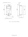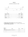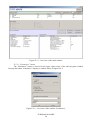
1
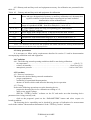
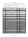
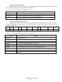
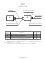
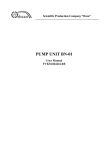
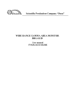
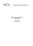
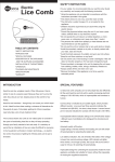
Scientific Production Company “Doza” DETECTING DEVICE UDMN-100 User Manual FVKM.468166.010RE Cont ent 1 Description and operation of the product …………..………...………. 1.1 Product functionality ………………………….…….………… 1.2 Technical characteristics ………………………………………. 1.3 Configuration …………………………………….….………… 1.4 Design and operation …………....……………...……………... 1.5 Marking and sealing …………………...……………………… 1.6 Packing ………………………………………………………... 2 Intended use …………………………………………………..…….… 2.1 Operational limitations …………………………………...…… 2.2 Preparation of the product for use ..…………………………… 2.3 Use of a product …….….….………………………..…………. 2.4 Adjustment ……………………………………….…………… 3 Maintenance ……………………………………………..…………… 3.1 General notes …………………………………...……………... 3.2 Safety precautions …………………………………………..… 3.3 Maintenance routine …………………………………………... 4 Calibration routine ……………….…………………………………… 4.1 General requirements ………………………………...………... 4.2 Preliminary arrangements ……………………….….……….... 4.3 Safety precautions ……………………………….………….… 4.4 Conditions ….……….………….………….…….…….……… 4.5 Procedure …………………….…………………..…………… 5 Routine repairs ……………………………………………...………... 6 Storage ………………………………………………………………... 7 Transportation ……………………………………………….……….. 8 Disposal …………..…………………………………………..……..... 3 3 4 6 6 8 8 8 8 9 9 9 9 9 9 10 10 10 10 11 11 11 12 12 12 13 Appendix A Description of data exchange registers using the DiBUS protocol ……………………………………….…………… Appendix B Wiring diagram ………………...……………….………………. Appendix C Outline drawing ….……………………...……...………………. Appendix D Assembling the signal cable ……………………………….…… Appendix E Software“TETRA_Checker” User manual ……………….….…. 14 16 18 22 23 FVKM.468166.010RE 2 This user manual contains information on design, principle of operation, characteristics of the product and instructions essential for correct and safe use of this product (intended use, maintenance, servicing, storage and transportation), as well as information regarding the utilization of the product. 1 DESCRIPTION AND OPERATION OF THE PRODUCT 1.1 Product functionality Detecting devices UDMN-100 FVKM.468166.010 (hereinafter – detecting devices) are * 10 of neutron radiation (hereinafter intended for measurement of the ambient equivalent dose rate AEDR). Detecting devices are used for radiation monitoring at the facilities involved in production, processing and use of radioactive materials, facilities manufacturing and/or using radiation sources, at nuclear plants including nuclear plants of nuclear-powered vessels. Detecting devices are able to convert measurement information into data with content and formatting complying with the DiBUS data exchange protocol and to transfer the data to external information channels via communication lines with RS-422 or RS-485 interface. Detecting devices can be operated as standalone units or as part of the radiation monitoring systems, complexes and installations. Table 1.1 describes modifications of detecting devices that differ by interface units. Table 1.1 – Modifications of detecting devices Designation FVKM.468166.010 FVKM.418266.004 FVKM.408844.005 FVKM.468166.010-10 FVKM.418266.004 AJAH.418292.017 FVKM.468166.010-11 FVKM.418266.004 AJAH.418292.017-01 FVKM.468166.010-20 FVKM.418266.004 AJAH.418292.018 FVKM.468166.010-21 FVKM.418266.004 AJAH.418292.018-01 Description Detecting device UDMN-100 including: Detector BDMN-100-07 Interface unit BS-12 Detecting device UDMN-100-01DD including: Detector BDMN-100-07 Interface unit BS-12-01DD Detecting device UDMN-100-01PD including: Detector BDMN-100-07 Interface unit BS-12-01PD Detecting device UDMN-100-02DD including: Detector BDMN-100-07 Interface unit BS-12-02DD Detecting device UDMN-100-02PD including: Detector BDMN-100-07 Interface unit BS-12-02РD FVKM.468166.010RE 3 Interface type RS-485/RS-422 RS-422 Signalling feature RS-485 Signalling feature RS-422 Signalling and indicator features RS-485 Signalling and indicator features 1.2 Technical characteristics 1.2.1 Energy range of measured neutron radiation …….…..……...….…..….. 0.025 to 10.0 MeV. 1.2.2 Measurement range of the AEDR of neutron radiation …….……… 1 10-7 to 1 10-1 Sv·h-1. 1.2.3 Limits of the permissible basic relative measurement error of AEDR of neutron radiation ..…………………………………….……………………………………….……...….. 25 %. 1.2.4 Energy dependence for typical neutron spectra relative to the value obtained with neutron spectrum of Pu-Be source ………….…………………………………..………………….……. ± 40 %. 1.2.5 Anisotropy of the detecting device in the plane of longitudinal axis of the detector ±35 %. 1.2.6 Detecting device warm-up time ……….......….…………………….. not more than 1 min. 1.2.7 Continuous operation without limitation of number of turning on/off ................ unlimited. 1.2.8 Instability during 24 hours of continuous operation relative to the mean value of readings for this period ..………………………..……………………….………………… not more than ±10 %. 1.2.9 Power supply DC voltage …………………………...….…….…..…………... (24 12) V. 1.2.10 Current consumption at voltage 24 V …………………..……..….. no more than 50 mA. 1.2.11 Blocks provide generation of self-diagnostics codes and current measurement information for the external information network based on RS-422/RS-485 interface (DiBUS data exchange protocol). For the description of data exchange registers in the DiBUS protocol see Appendix A. 1.2.12 Operating conditions: 1) operating temperature range: - detector BDMN-100-07 ….…………………………..……………..… minus 45 to + 50 C, - interface units BS-12 and BS-12-01DD (PD) ....……...…...………..… minus 40 to + 50 C; - interface units BS-12-02DD (PD) ....………...…………………...….. minus 40 to + 50 C without indication of measurement results on LCD, - interface units BS-12-02DD (PD) ....………......................………..… minus 20 to + 50 C with indication of measurement results on LCD; Not e – Detecting devices with operating temperature range from minus 45 to + 60 C are available by request. 2) relative humidity ……..………………..……………………….…..……up to 98 % at +35 C; 3) atmospheric pressure ……………………………….……..…………….… 84.0 to 106.7 kPa; 4) content of the corrosive agents in the ambient air corresponds to the values in Table 1.2. Table 1.2 Type of atmosphere Content of the corrosive agents Designation Description Sulfur dioxide gas no more than 20 mg/(m2·day) (not more than 0.025 mg/m3); I Relatively clean Chlorides no more than 0.3 mg/(m2·day) Sulfur dioxide gas no more than 20 to 250 mg/(m2·day) (not more than 0.025 to 0.31 mg/m3); II Industrial Chlorides no more than 0.3 mg/(m2·day) Sulfur dioxide gas no more than 20 mg/(m2·day) III Maritime (not more than 0.025 mg/m3); Chlorides – 30 to 300 mg/(m2·day). 1.2.13 Limits of complementary error of the AEDR of gamma radiation: - due to deviation of temperature from its normal value per 10 C……………...……… ±5 %; - under increased relative humidity up to 98% at +35C ………………………………..±5 %. 1.2.14 Detecting devices withstand sinusoidal vibrations in the frequency range from 10 to 55 Hz with displacement amplitude 0.35 mm. FVKM.468166.010RE 4 1.2.15 Detecting devices are stable against seismic impacts with magnitude 7 according to the MSK-64 scale, being installed on the building structures of the industrial site at 70 to 30 m relative to the grade level. After the seismic impact with the above mentioned parameters detecting devices are operable within the limits stated in sections 1.2.3, 1.2.11, during the whole life cycle under specified operation conditions. 1.2.16 Degree of protection provided by casings against ingress of solid items and water IP65. 1.2.17 Detecting devices are stable against electromagnetic interference of 3 grade according to the IEC 1000-4-8-93, IEC 1000-4-9-93, IEC 61000-4-2-95, IEC 61000-4-3:2006, IEC 61000-4-4:2004, IEC 61000-4-5-95, IEC 61000-4-6-96, IEC 61000-4-12-95 and comply with the emission standards stated by the CISPR 22:2006 for equipment of class A. 1.2.18 Detecting devices are stable against short (duration 5 minutes) overloads of the monitored radiation with AEDR of neutron radiation 1 Sv·h-1. After the overload devices are operable, basic relative measurement error remains within limits stated in the 1.2.3. 1.2.19 Detecting devices are operable after exposure to gamma radiation with AEDR up to 10 Sv·h-1 and 5 minutes duration. 1.2.20 Detecting devices are stable under conditions of background gamma radiation with AEDR up to 0.01 Sv·h-1. Limits of complementary measurement error of AEDR under conditions of background gamma radiation with AEDR up to 0.01 Sv·h-1 relative to the measurement results at AEDR of neutron radiation of 1.0 mSv·h-1 – no more than ±10 %. 1.2.21 By its protection against electric shock detecting devices comply with the IEC 61010-1:2001. 1.2.22 Detecting devices are fire-safe products with fire probability of no more than 10-6 year-1. 1.2.23 Detecting devices withstand the exposure to decontaminating solutions: 1) boric acid (H3BO3) – 16 g, sodium thiosulfate (Na2S2O3·5H2O) – 10 g, distilled water – up to 1 liter; 2) trisodium phosphate or sodium hexametaphosphate (any detergent) – 10 - 20 g/l water solution; 3) 5 % citric acid solution in rectified alcohol – for connectors and contacts. 1.2.24 Overall dimensions and weight, no more than: 1) detector BDMN-100-07: - with handle …………………………………………………..………...... 316×240×290 mm, - with light-weight attachment fitting ………………..………………….... 254×256×350 mm, - with wall mounting ………………………………………………...….... 428×258×347 mm; 2) interface unit: - BS-12 ……………..……...……….…..………………...…………..….….. 8064170 mm, - BS-12-01DD (PD), BS-12-02DD (PD) …………………………………… 8075220 mm. 1.2.25 Weight, not more than: - detector BDMN-100-07 with handle ………..………...…………...…..………..….. 11.5 kg; - with light-weight attachment fitting ……………………….……………………….... 3.2 kg; - wall mounting ……………………………………………………..….….…………. 14.3 kg; - interface unit BS-12 ……….……………….………..….…..…...……………..…..… 0.8 kg; - interface unit BS-12-01DD (PD), BS-12-02DD (PD) ……….….....…………..…..… 0.8 kg. 1.2.26 Communication cable length between detector BDMN-100-07 and interface unit up to 20 m. 1.2.27 Total cable length between all elements of the information network (in which the device is included) and data processing device (detecting device that receives and process information) …………………………………………………………………..….………. up to 1200 m. Type of cable – FTP-4, category 5. FVKM.468166.010RE 5 1.2.28 Mean time before failure …………………………...…..……. not less than 10000 hours. 1.2.29 Mean life time ……………………………………….………..…. not less than 10 years. 1.3 Configuration 1.3.1 The detecting device includes detector BDMN-100-07 and interface unit BS-12 or BS-1201DD (PD), or BS-12-02DD (PD), connected by the signak cable. The following accessories are supplied by customer’s request: - cable socket ONC-BS-1-10/14 – for assembling communication cable for connection to PC; - interface converter PI-02 – for connection to PC; - software “TETRA_Checker” developed for adjustment, calibration and verification of detecting device. 1.3.2 Cable for connection with PC is not included in the delivery kit; it is assembled by the customer using the cable plug from the delivery kit in accordance with the wiring diagram (Appendix B). 1.4 Design and operation 1.4.1 Detector BDMN-100-07 (hereinafter - detector) consists of spherical neutron moderator with detector module placed inside it. Detector module is comprised of: - scintillation detector based on LiF, enriched in 6Li isotop to 85%, and ZnS(Ag), placed in the plexiglass for conversion of slow/thermal neutrons into scintillations (flashes of light); - PMT tube – for registration of scintillations; - high voltage converter – for high voltage supply to the PMT; - amplifier-discriminator – for amplifying and selection by amplitude of pulses from the PMT; - conditioner – for conditioning of the output signal and its transfer to the interface unit. 1.4.2 Neutron moderator is intended for deceleration and thermalization of fast neutrons. Neutron moderator can be of portable version with handle, alternatively it can be equipped with a light-weight attachment fitting or a wall mounting. Outline drawing of the neutron moderator are presented in the Appendix C. 1.4.3 Interface unit BS-12 or BS-12-01DD (PD), or BS-12-02DD (PD) (hereinafter – “interface unit”) includes: - voltage convertor with galvanic isolation – for power supply to the internal circuits of the interface unit and the detector; - processor – for conversion of the pulse sequence received from the detector to data containing measurement information about the AEDR; - communication chips with galvanic isolation – for transfer of a signal with parameters complying with RS-422 or RS-485 interface, via long cable. In addition, interface units BS-12-01DD (PD) are equipped with sound-and-light signalling with a button for muting an audible signal. In addition, interface units BS-12-02DD (PD) are equipped with sound-and-light signalling with a button for muting an audible signal and LCD for displaying the measurement results. Interface unit is secured in place using bracket. Overall and fitting dimensions of interface units are presented in the Appendix C. 1.4.4 Operating principle of detecting device is based on conversion of the ionizing radiation energy into electric pulses. FVKM.468166.010RE 6 The interface unit processes and converts measurement information received in a form of statistically distributed and conditioned pulses into information about the EDR of neutron radiation. The format of information obtained as a result of such transformation is defined by the DiBUS data exchange protocol that provides possibility of data transfer to the external devices intended for visualization, storage, and alarm signalling. The interface units BS-12-01DD (PD) and BS-12-02DD (PD) generate light and sound signals when AEDR exceeds the alarm threshold. Besides the above mentioned functions interface units BS-12-01DD (PD) also provide indication of AEDR measurement results on the LCD. * 10 1.4.5 By request of an external device, interface unit returns measured value of AEDR (Sv/h) at the time of request, calculated by the formula * 10 K N 1 MN (1.1) where К – sensitivity coefficient, Sv h-1 s; N – frequency of pulses (count rate), s-1; M – “dead time”, s. Not e – Typical value of sensitivity is K = 2.0·10-6 Sv·h-1·s and of “dead time” – М = 23.0 μs. Sensitivity coefficient and “dead time” are written in the nonvolatile memory of the interface unit at the time of adjustment. Reading and changing of these parameters, as well as other adjustment and calibration operations are performed using the “TETRA_Checker” software (SPC “Doza”. www.doza.ru). 1.4.6 The user can select one of the following algorithms of count rate measurements: “Sliding” and “Following”. 1.4.6.1 The “Sliding” algorithm (moving average method) provides continuous measurement of the count rate. The measurement result is determined as an arithmetic mean of separate readings that corresponds to measurement intervals of user-selected duration, and with the number of readings to be averaged also determined by the user. The algorithm includes two parameters: - the number of elementary measurements (interval quantity), which can be set to any value between 1 and 60; - duration of the measurement interval (interval time), which can be set to any value between 1 and 65535 seconds. Measurement interval is a period between two subsequent readings (refreshing a measurement result). The default measurement interval set by the manufacturer is 20 seconds. The product of measurement interval time and a number of such intervals represents the averaging time when measuring count rate. The greater this product is the lesser is the statistical uncertainty of measurement; however the response time to changes of the measured quantity is also greater. 1.4.6.2 Algorithm “Following” allows tracking smooth variations, as well as record jumps of the measured quantity. The “Following” algorithm is characterized by a fast response to the measured quantity jumps which exceed the mean value by more than 3σ, where ; N – frequency of pulses (s-1) corresponding to the numerical value of jump-like change. At constant frequency of pulses the averaging time is 200 seconds. FVKM.468166.010RE 7 1.4.7 The measurement result is compared with preset thresholds each second; the following thresholds are limiting the tunnel of allowable AEDR of neutron radiation: - “Alarm threshold” – this threshold defines the upper limit of the tunnel; - “Preliminary threshold” – this threshold sets the warning level; - “Bottom threshold” – the bottom of the tunnel, signal falling below the bottom line is usually evidence about the detector failure or decreasing of the controlled process intensity below allowable limit. In case when zero value of the threshold is set – it is inactive. 1.4.8 Detecting devices require external stabilized power supply. Wiring diagram and assignment of the connectors’ contacts are presented in the Appendix B. 1.4.9 Interface units ensure galvanic isolation of the electronic circuit elements of the interface unit and detector from the circuits of the information network (“LINE” connector of the interface unit). 1.5 Marking and sealing 1.5.1 Detector casings have one nameplate with the following information: - trademark and name of the manufacturer (supplier); - designation of a detecting device of which the unit constitutes a part; - reference designation of the detector; - works number according to the manufacturer's system of numeration; - degree of ingress protection. 1.5.2 Interface units have two nameplates on their casings: 1) one nameplate contains the following markings: - trademark or name of the manufacturer, - reference designation of the interface unit, - works number of Interface unit according to the manufacturer's system of numeration, - pattern approval mark of the measurement instrument, - made in Russia; 2) another nameplate contains the following markings: - trademark or name of the manufacturer, - designation of a device of which the unit constitutes a part, - designation of the interface unit, - works number according to the manufacturer's system of numeration, - degree of ingress protection. 1.5.3 Place and method of marking of elements constituting the detecting devices comply with the design documentation. 1.5.4 All elements constituting the detecting devices are sealed in accordance with the design documentation. 1.6 Packing 1.6.1 The detecting devices package complies with the design documentation and provides protection against ingress of atmospheric precipitations and aerosols, splashes of water, dust, sand, solar ultra-violet radiation and limits the ingress of water vapour and gases. 2 INTENDED USE 2.1 Operational limitations 2.1.1 Detecting devices can be used with installations equipped with corresponding data exchange interface and providing power supply with required voltage for detectors. FVKM.468166.010RE 8 2.1.2 The following is not allowed during operation: - use of detecting devices at medium (6 – 35 kV) and high (above 35 kV) voltage electric substation; - use of detecting devices as parts of high power electric installations; - connection of detecting devices to the circuit of signal earth; - use of mobile phones within 10 meters of the detecting devices. 2.2 Preparation of the product for use 2.2.1 For preparation of the detecting devices for use: - mount elements of the detecting devices; - connect the detector to the “BD” connector of the interface unit by means of signal cable in accordance with Appendix B; if necessary, arrange soldered connections and perform assembling of the signal cable in accordance with Appendix D; - connect the “LINE” connector of the interface unit to PC using a communication cable, through the interface converter RS-232/RS-485(RS-422) or USB/RS-485(RS-422), as shown in the Appendix B; communication cable shall be assembled by the user with the help of cable socket ONCBS-1-10/14 in accordance with the diagram in the Appendix B; - apply power supply voltage; - start the “TETRA_Checker” software on PC as described in the Software User Manual (Appendix E) and make sure that detecting devices parameters have being correctly read. 2.2.2 The detecting devices operability can be checked by presence of indication of measurement result in the window “Measuring data” of the “TETRA_Checker” software. 2.3 Use of a product 2.3.1 Detecting device does not require any actions of personnel during their operation. Measurement results are transferred to the external communication channel based on the RS-485 interface (DiBUS data exchange protocol). 2.4 Adjustment 2.4.1 Before performing adjustment prepare the detecting device according to 2.2. 2.4.2 Change of linear sensitivity factor K of the detector is performed by correcting the “Sensitivity index” parameter using the “TETRA_Checker” software according to the formula (1.1). Change of this parameter results in proportional change of the indications within all measurement range. 2.4.3 Correction of indications in the end of the range (more than 0,4 of the upper limit of measurement range) is performed by adjusting the “dead time” using the “TETRA_Checker” software. Increasing “dead time” results in increasing indications at high count rates only. 3 MAINTENANCE 3.1 General notes 3.1.1 Maintenance is performed with the purpose of ensuring correct and long-term operation of detecting devices. 3.1.2 Operating personnel who has basic computer user skills and skills of working with dosimetric equipment are permitted for maintenance of the detecting devices. 3.2 Safety precautions 3.2.1 Before beginning to work with detecting devices familiarize yourself with this User Manual. FVKM.468166.010RE 9 3.2.2 During all operations with detecting devices it is necessary to follow occupational and radiation safety requirements of current safety instructions in the company (enterprise). 3.2.3 All cable connections and disconnections should be performed with the power supply cut off. When using detecting devices as part of measurement information complexes, systems and installations “hot” connection of cables is allowed (without switching detectors off). In this case the protective earth should be connected to corresponding terminals of the detector and of the device receiving signals from detecting devices. 3.3 Maintenance routine 3.3.1 Maintenance is divided into routine and periodic. 3.3.2 Routine maintenance 3.3.2.1 Routine maintenance is carried out during regular operation; it includes inspections of detectors for timely detecting devices and elimination of factors which can compromise their operability and safety. 3.3.2.2 The following main types and periodicity of routine maintenance are recommended: - visual inspection ……………………………………………….………..…….. every month; - cleaning of external surfaces (decontamination) .……………….…..……...…… every year. 3.3.2.3 During visual inspection conditions of cables and connectors and reliability of securing are assessed. 3.3.2.4 Decontamination of detecting devices is performed in accordance with work schedule at the company (facility): - external surfaces of detecting devices are decontaminated using solutions 1) and 2) of the 1.2.23: after cleaning surfaces using cloth moisten with decontaminating solution it is necessary to wipe surfaces using cloth moisten with distilled water and then dry using filter paper; - cable connectors are decontaminated using solutions 3) of the 1.2.23: additional treatment with distilled water and drying with filter paper are not required. Dry cleaning can be performed with any periodicity. Detecting devices should be disconnected from the power supply before dry cleaning and/or decontamination. 3.3.3 Periodic maintenance Periodic maintenance consists of calibration of detectors. Adjustment of detecting devices is allowed when necessary in accordance with section 2.4. 4 CALIBRATION ROUTINE 4.1 General requirements 4.1.1 Calibration of detecting devices are performed in accordance with the IEC 61453:2007. 4.2 Preliminary arrangements 4.2.1 Operations that should be performed during calibration are listed in the table 4.1. Table 4.1 – List of calibration operations Operation Section of the document 1 External examination 2 Testing 3 Determination of basic relative measurement error of AEDR of neutron radiation FVKM.468166.010RE 10 4.5.1 4.5.2 4.5.3 4.2.2 Primary and auxiliary tools and equipment necessary for calibration are presented in the table 4.2. Table 4.2 – Primary and auxiliary tools and equipment for calibration Item 4.5.3 4.5.2, 4.5.3 4.5.2, 4.5.3 4.5.3 4.5.3 4.5.3 4.5.3 Name and type (designation) of primary or auxiliary calibration tool, document that regulates technical requirements and/or metrological and main technical characteristics of the calibration tool Calibration installation UCPN-2M-D (complies with TU 4362-052-31867313-2005). Range of reproduced AEDR – from 20 to 800 μSv·h-1, error ±15 % PC with technical means for using corresponding port, with installed “TETRA_Checker” software Power supply with voltage (2412) V and current not less than 100 mA Stopwatch with measurement range 1 to 3600 seconds Thermometer with measurement range 0 to 30 °C and scale interval 0.1 °C Psychrometer with measurement range 20 to 90 %, error ±6 % Barometer with measurement range 60 to 120 kPa and scale interval 1 kPa Not e - It is allowed to use other tools and equipment with similar characteristics ensuring determination of metrological characteristics of detectors with required precision. 4.3 Safety precautions It is necessary to follow safety requirements described in section 3.2 and in documentation accompanying calibration tools and equipment. 4.4 Conditions 4.4.1 The following normal operating conditions shall be met during calibration: - air temperature …………………………………………….….………………. +(20 ±5) °C; - relative air humidity ……….………………………….....….…..……...… from 30 to 80 %; - atmospheric pressure ………………………………………………….… 84.0 to 106.7 kPa. 4.5 Procedure 4.5.1 External examination The items to be checked during external examination: - proper completeness; - availability of operational documentation; - absence of defects which could affect the detecting device operation. 4.5.2 Testing Perform the following operations to test the detecting device: - prepare the detecting device for calibration according to 2.2; - apply power supply voltage; - Start the “TETRA_Checker” software on the PC and make sure that detecting device parameters have being correctly read; - click on the program’s panel on the “PARAMETERS” button and select request via broadcast address. The detecting device operability can be checked by presence of indication of a measurement result in the window “Measurement Information”of the “TETRA_Checker” software. FVKM.468166.010RE 11 4.5.3 Determination of basic relative measurement error of AEDR of neutron radiation 4.5.3.1 Determine the basic relative measurement error by means of successive exposure of the detector to a set of AEDR of neutron radiation in the ranges from 10 to 100 μSv·h-1 and from 300 to 700 μSv·h-1. 4.5.3.2 For taking measurements detector should be placed in the radiation field of the calibration installation so that the axis of the collimated beam be perpendicular to the longitudinal axis of detector and pass through the center of the neutron moderator. 4.5.3.3 Determine measurement results at the first and the second AEDR points as the average of five readings taken with interval of 100 seconds for each point. 4.5.3.4 Calculate the relative error of AEDR of neutron radiation in per cent using the following formula * H * H 0 (4.1) * 100 H 0 * - AEDR value as measured by the detecting device, μSv·h-1; where Н * - is the AEDR value reproduced by the calibration installation, Sv·h-1. Н 0 The detecting device is considered valid if the main relative error of measurement at both points does not exceed the value stated in the 1.2.3. If the relative error exceeds limit, perform correction of sensitivity coefficient and “dead time” in accordance with the section 2.4. Allowable range of correction of sensitivity coefficient is 1.5·10-6 to 2.5·10-6. It is recommended to perform correction of sensitivity coefficient using the range 10 to 100 μSv·h-1, the “dead time” is fixed at 23 μs and is not changed during calibration. 5 ROUTINE REPAIRS 5.1 Routine repairs include restoration of damaged cables and connectors. 6 STORAGE 6.1 Prior to putting into operation detecting devices shall be stored in a heated warehouse with natural ventilation: - in manufacturer’s package – at ambient temperatures from +5 to +40 C and relative humidity up to 80 % at +25C; - unpacked – at ambient temperatures from +10 to +35 C and relative humidity up to 80 % at +25 C. 6.2 The storage location should be free of dust, chemical vapours, aggressive gases and other substances that may cause corrosion. The storage location shall exclude exposure of the detecting devices to the direct rays of sunlight. 7 TRANSPORTATION 7.1 Detecting devices in the original manufacturer’s package can be transported by all means of transport at any distance: - transportation by railway shall be carried out in clean boxcars; - when transported by open motor transport boxes shall be covered by the water-proof material; - when transported by air the boxes with detecting devices shall be placed in air-tight heated compartment; FVKM.468166.010RE 12 - when transported by water and sea transport the boxes with detecting devices shall be placed in the hold. 7.2 Arrangement and fastening of the boxes on transport means shall provide their steady position en route, absence of displacement and striking each other. 7.3 The requirements of the inscriptions on the transport packing shall be observed during loading and unloading. 7.4 Transportation conditions are as follows: - temperature …………………………………………………..….. from minus 50 to +50 °C; - humidity …………………………………….………………....…..… up to 98 % at +35 °C; - sinusoidal vibrations ………………………….. within frequency range from 10 to 55 Hz with displacement amplitude 0.35 mm. 8 DISPOSAL 8.1 On full expiry of the detecting devices (its component parts) service life and also prior to its dispatching for repair or calibration it shall be inspected for possible radioactive contamination of its surfaces. Criteria for decision making on decontamination and further use shall comply with obligatory requirements of national standards. 8.2 Decontamination shall be attempted in cases when the detecting devices surfaces contamination (including surfaces accessible during repair) can be reduced below allowable limits. In case the radioactive contamination exceeds allowable limits, requirements set forth for the radioactive wastes become applicable to the detecting devices. 8.3 Detecting devices accepted for operation after decontamination are subjects for repair or replacement in case of failure. Detecting devices not suitable for operation, with radioactive contamination levels below permissible limits, should be dismantled to prevent further use and transferred to a special site for disposal of industrial wastes. 8.4 Detecting devices with expired lifetime, accepted for use after decontamination, shall undergo technical inspection. If the technical condition of a detecting devices is satisfactory, an extended operation term of the product shall be determined. FVKM.468166.010RE 13 Appendix A (Reference) DESCRIPTION OF DATA EXCHANGE REGISTERS IN THE DIBUS PROTOCOL А.1 Data for reading from and writing to the detecting devices A.1 Data for reading from and writing to the detecting devices are interrogated in accordance with indices indicated in the table A.1. Table A.1 - Data for reading from and writing to the detecting devices Index Description 0×0c 0×0d 0×0f For calibration of the detecting device Date of manufacturing of the detecting device Value of the selected measured quantity + status Combined package: 0×09 Instantaneous value of the measured quantity set as “DEFAULT”, number of pulses for calculation of instantaneous value and unique ID 0×10 Value of selected measured quantity 0×13 Measurement interval of the selected measured quantity 0×14 Measurement uncertainty 0×18 Status of the detecting device 0×19 Description of the selected command of the restart of measurement 0×1c Detecting device code 0×1d Net address of the detecting device 0×1f Date and time of the detecting device Measured quantities 0×22 AEDR, Sv·h-1 0×23 Interval for EDR measurement, s 0×24 Measurement uncertainty, % 0×2c Average count rate, counts per second (cps) 0×89 Hours worked Parameters 0×71 Alarm threshold, Sv/h 0×73 Preliminary threshold, Sv/h 0×75 Bottom threshold, Sv/h 0×77 Algorithm (0 – “Following”; 1 – “Sliding”) 0×79 interval quantity (Sliding) 1 - 60 0×7b interval time (Sliding), seconds 1 - 65535 0×7d Sensitivity coefficient 0×7f Dead time, μs 0×81 K1 0×83 K2 0×85 K3 0×87 DB accumulated dose, Sv 0×8b Self background, Sv·h-1 FVKM.468166.010RE 14 R/R/R/- Type Name (number) Long_DateTime(31) Long_DateTime(31) BYTE(1) R/- BYTE(1) R/R/- Single (25) DWORD (11) R/R/-/W BYTE(1) WORD (5) BYTE(1) R/-/W R/W BYTE(1) DiBUS_address (33) Long_DateTime(31) R/R/R/R/R/- Single (25) DWORD (11) BYTE(1) Single (25) DWORD (11) R/W R/W R/W R/W R/W R/W R/W R/W R/W R/W R/W R/W R/W Single (25) Single (25) Single (25) Single (25) Single (25) Single (25) Single (25) Single (25) Single (25) Single (25) Single (25) Single (25) Single (25) R/W A.2 Restart of measurement Register 0x19 is used for restarting of measurement of the N-th measured quantity. The list of values written to this register is presented in the table A.2. Table A.2 - Values written to the register 0×19 Written value Description 0×00 Restart of measurement of selected measured quantity N [1;0×fe] Restart of measurement of N-th measured quantity 0×ff Restart of measurement of all measured quantities A.3 Status of the detecting device Register with index 0×18 is used for determination of the detecting device status. The value 0×0000 corresponds to normal state of the detecting device. Flags of the status register 0×18 are presented in the table A.3. 15-11 10 9 8 7 6 5 4-3 2 1 0 R RRP DVRD R THRRF THRPF THRPF R MEMERR BDBRF SCRTF Table A.3 - Description of flags of the status register 0×18 Flag Purpose SCRTF 1 – Short circuit BDBRF 1 – Detector is out of order MEMERR 1 – malfunction of the nonvolatile memory THRPF 1 – Alarm threshold threshold is exceeded THRPF 1 – Preliminary threshold is exceeded THRRF 1 – The measured value is below the “Bottom threshold” DVRD 1 – Detecting device is not ready RRP 1 – Parameters were changed R Reserved FVKM.468166.010RE 15 Appendix B (Obligatory) WIRING DIAGRAM Signal cable Plug ONC-BS-1-10/14-V1-1-V Cable for connection А2 А1 Plug ONC-BS-1-7/12-M1-1-V Item designation Socket ONC-BS-1-10/14-R12-1-V Description Q-ty A1 Detector BDMN-100-07 FVKM.418264.004 1 A2 Interface unit BS-12 FVKM.408844.005 1 A1 Interface unit BS-12-01DD (PD) AJAH.418292.017 (-01) 1 A2 Interface unit BS-12-02DD (PD) AJAH.418292.018 (-01) 1 Note Assignment of contacts of the plug ONC-BS-1-7/12-V1-1-V is presented in Table B.1, and of plug ONC-BS-1-10/14-V1-1-V in Table B.2. Arrange soldered connections of the signal cable in accordance with Appendix D. FVKM.468166.010RE 16 Table B.1 – Assignment of contacts of the plug ONC-BS-1-7/12-V1-1-V Contact 1 2 4 5 6 7 Signal + 12 V. Control Output Common (screen) Common (screen) Table B.2 – Assignment of contacts of the plug ONC-BS-1-10/14-V1-1-V For RS-422 interface (DD) Contact 1 4 5 6 8 9 10 Signal +(24 12) V Reception+ ReceptionTransmission+ TransmissionCasing Common For RS-485 interface (PD) Contact 1 4 5 6 8 9 10 FVKM.468166.010RE 17 Signal +(24 12) V Data+ DataCasing Common Appendix C (Obligatory) OUTLINE DRAWING Detector module FVKM.305615.001 Figure C.1 – Detector BDMN-100-07 with handle Figure С.2 – Detector BDMN-100-07 with light-weight attachment fitting FVKM.468166.010RE 18 Neutron moderator Wall mounting 4 holes Detector module Figure С.3 – Detector BDMN-100-07 with wall mounting FVKM.468166.010RE 19 Figure C.4 – Interface unit BS-12 FVKM.468166.010RE 20 Plug ONC-BS-1-10/14-V1-1-V Ø 4.5 2 holes ONC-BS-1-7/12-V1-1-V Figure C.5 – Interface unit BS-12-02DD (PD) FVKM.468166.010RE 21 Appendix D (Obligatory) ASSEMBLING OF THE SIGNAL CABLE FVKM.468166.010RE 22 Appendix E (Obligatory) SOFTWARE “TETRA_Checker” USER MANUAL Cont ent E.1 Purpose of the software ………………………………….….….…… E.2 Description of the interface …………………...……………….……. E.2.1 Overview of the main window ……………….………………. E.2.1.1 “Parameters” button ………………………..……….……… E.2.1.2 Information panel ………………………….…….….……… E.2.1.3 “Measuring data” panel ……………………….……………. E.2.1.4 “Device status” panel ………………………………………. E.2.1.5 “Device parameters” panel …………………………………. 23 23 23 24 25 25 25 26 E.1 PURPOSE OF THE SOFTWARE The “TETRA_Checker” software (hereinafter – “program”) is intended for adjusting and calibration of devices and detectors (hereinafter – “device”). The program allows doing the following: - read and indicate values of the device parameters; - write the net address into the device; - write values of the dynamic parameters into the device; nomenclature of parameters is defined by the device itself; - select one of the measured quantities in the device as a quantity requested by default; - indicate information about the operation of the device and measurement results on the monitor of personal computer; - indicate the device status information on the monitor of personal computer. ATTENTION! BUGS ARE POSSIBLE WHEN USING THE PROGRAM SIMULTANEOUSLY WITH NET CLIENTS (ICQ clients, Skype, GTalk, Jabber etc.). IF THIS IS THE CASE IT IS RECOMMENDED TO CLOSE ALL ABOVE MENTIONED CLIENTS (SOFTWARE) AND RESTART THE PROGRAM. E.2 DESCRIPTION OF THE INTERFACE E.2.1 Overview of the main window The overview of the program’s main window is shown on the figure D.2.1. In the main window the following interface elements are located: - “Parameters” button; - Information panel; - “Measuring data” panel; - “Device status” panel; - “Device parameters” panel. FVKM.468166.010RE 23 Figure E.2.1 - Overview of the main window E.2.1.1 “Parameters” button The “Parameters” button is located in the upper right corner of the main program window. Pressing the button “Parameters” displays a window shown in figure D.2.2. Figure E.2.2 – Overview of the window “Parameters” FVKM.468166.010RE 24 The following can be done using the window “Parameters”: - selection of the serial port to which the device is connected; - setting extra waiting time of device’s reply which may be necessary when additional devices (radio modems, protocol convertors etc.) are present in the information channel (between the device and personal computer); - selection of the program’s mode of operation with the device; operation with individual device is fulfilled in the mode of requests using the broadcast address, i.e. without indicating the net address of the device; interrogation of the specified address is necessary when selection of a single device is needed from the functioning system or installation. E.2.1.2 Information panel Information panel is located in the upper part of the main window to the left from the “PARAMETERS” button. The following is displayed on the information panel: - in the course of the device preparation for measurements – message banners related to the device preparation for switching to operating mode; - in the course of measurements – measurement result of the “default” measured quantity; - in case of failures during data exchange with PC – information on errors. The following messages may be displayed on the information panel in different situations when failures occur during data exchange: - “COM-port error” – probably the non-existent port was selected or port is busy by another program; recommended actions – select correct port or release port by shutting down the concurrent program; - “No reply” – this message appears when the device is not connected or the conversion mode of the matching device (RS-232 to RS-485/RS-422) is incorrect; - “Read error” – probably in the broadcast request mode several devices answer simultaneously, it is recommended to switch to request mode with specific net address or, working in the broadcast request mode, disconnect from the data way all devices except the one you need. E.2.1.3 “Measuring data” panel As a rule, “Measuring data” panel contains several lines, each of which contains: - name of measured quantity “Measurand”; - measurement unit of the measured quantity “Unit”; - current reading, measurement result “Result”; - measurement interval “Time, s”; - error of the measurement result “Measurement uncertainty”. In the upper part of the panel the following buttons are located: - “Set current algorithm” – for selection of the quantity to be measured by default by the device. Measurement result for the measured quantity will be displayed on the information panel. On the “Measurement information” panel corresponding line will be highlighted in color; - “Restart measurement F5” – for initiating new measurement cycle for certain measured quantity; - “Restart all F4” – for initiating new measurement cycles for all measured quantity. E.2.1.4 “Device status” panel On the “Device status” panel the information is displayed with regard to current state of the device and other device specific information: - readiness of the device for measurement; - different errors which occurred during the device operation; - results of comparison of the measured values with preset thresholds, etc. FVKM.468166.010RE 25 E.2.1.5 “Device parameters” panel E.2.1.5.1 The “Device parameters” panel contains information about static parameters, which are not used in the measurements process, and dynamic parameters, which define measurement characteristics of the device, and also general information about the device operation. E.2.1.5.2 Static parameters: - Device address; - Device; - Device code; - Firmware version; - Configuration date; - Assembly date; - Device date/time; - Volume level; - Current device language; - Factory number: Parameter “Configuration date” is a variable; it is automatically changed when the “Set parameters” button is pressed. Parameter “device address” represents the net address of the device. E.2.1.5.3 Dynamic parameters Each device has its own set of dynamic parameters. Some parameters can possess the value of 0 or 1; some parameters can possess the value in the exponential form, for example 2.3E-003 (0.0023). Some parameters are “read only”, for example “Running hours”. Correction of the parameters is carried out as follows: - double click on the line of the parameter to be corrected; - in the column “New value” input new parameter value; - press “ENTER” or click on any other line; - if necessary, correct other parameters; - press the button “Set parameters F2”; - check correctness of the writing – new parameter values will be displayed in the column “Parameter point” after a while. ATTENTION! DECIMAL POINT (SEPARATOR BETWEEN INTEGER PART OF THE NUMBER AND THE FRACTION) IS USALLY A DOT (.). HOWEVER YOUR OPERATION SYSTEM CAN BE SET TO USE COMMA (,) INSTEAD. BE CAREFUL WHEN YOU INPUT NUMBERS. Sets of values or ranges of values of parameters are indicated in the operational documentation for each device. E.2.1.5.4 Buttons on the “Device parameters” panel In the upper part of the “Device parameters” panel the following buttons are located: - “DEVICE DATE/TIME” – this button is activated for devices that has or emulates built-in clocks; - “SET DEVICE LANGUAGE OF THE INTERFACE” – this button is activated for devices with multilanguage interface, it allows setting the active language of the device; - “SET VOLUME LEVEL” – this button is activated for devices equipped with adjustable signaling features, it allows to set the desired volume and, if necessary, to test it; - “SET ADDRESS” – in the broadcast mode this button allows to set the net address, for setting the address press the button “Set address”, then in the window that will appear input the new address – three dot separated groups of digits (3 digits in each group). The range of values in each group – from 002 to 254. After completion the input click “Ok”. The new address will be written into the non-volatile memory of the device. At the same time parameter “date of correction of parameters” is automatically set to current date; FVKM.468166.010RE 26 - “GET PARAMETERS…F3” – when the button F3 is pressed values of parameters on the “Device parameters” panel are refreshed; - “SET PARAMETERS…F2” – when the button F2 is pressed new values of the dynamic parameters are written into device. At the same time parameter “date of correction of parameters” is automatically set to current date. FVKM.468166.010RE 27