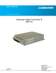
1
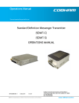
User’s Manual
The most important thing we build is trust.
Messenger High-Power Transmitter
(MHPT)
100-M0075X1
06/17/09
Cobham Surveillance
GMS Products
1916 Palomar Oaks Way Ste 100
Carlsbad, CA 92008
T: 760-496-0055
F: 760-496-0057
www.cobham.com/gms
Table of Contents
1.0 ACRONYMS................................................................................................................................................................ 3
2.0 THEORY OF OPERATION.................................................................................................................................. 4
3.0 HARDWARE OVERVIEW ................................................................................................................................... 5
3.1
MHPT Connectors.................................................................................................................................................6
3.1.1 RF Output.............................................................................................................................................................6
3.1.2 Data/Control.......................................................................................................................................................6
3.1.3 Audio .....................................................................................................................................................................6
3.1.4 DC in ......................................................................................................................................................................6
3.1.5 Y/CVBS ..................................................................................................................................................................6
3.1.6 C/Pr .........................................................................................................................................................................7
3.1.7 Pb.............................................................................................................................................................................7
3.1.8 SDI (Optional) ....................................................................................................................................................7
4.0 SOFTWARE OVERVIEW..................................................................................................................................... 7
4.1
System Requirements .........................................................................................................................................8
4.2
Installation ...............................................................................................................................................................8
4.3
MHPT Configurator Functions ........................................................................................................................8
4.3.1 Function Buttons...........................................................................................................................................10
4.3.2 Field Definitions.............................................................................................................................................10
4.3.3 Pull-Down Menu Definitions ....................................................................................................................12
4.3.3.1 File................................................................................................................................................................12
4.3.3.2 Configuration...........................................................................................................................................12
4.3.3.3 Help..............................................................................................................................................................15
5.0 GETTING STARTED........................................................................................................................................... 18
5.1
Initial Checkout...................................................................................................................................................18
6.0 SPECIFICATIONS .............................................................................................................................................. 20
6.1
Video Encoding...................................................................................................................................................20
6.2
Audio Encoding...................................................................................................................................................20
6.3
Transport Stream ...............................................................................................................................................20
6.4
RS-232 Interfaces/RCU/USB .........................................................................................................................20
6.5
COFDM RF Output.............................................................................................................................................20
6.6
Modulation ...........................................................................................................................................................21
6.7
Power.......................................................................................................................................................................21
6.8
Physical Dimensions (without mating connectors).............................................................................21
6.9
Environmental .....................................................................................................................................................21
6.10 MHPT Special Features....................................................................................................................................21
7.0 THE D/C (DOWN CONVERTER)/IF FREQUENCIES EXPLAINED ......................................... 22
7.1
IF Frequencies .....................................................................................................................................................22
7.2
Local and Remote Power ................................................................................................................................22
8.0 CABLE LOSSES...................................................................................................................................................... 24
8.1
Coax Cable............................................................................................................................................................24
100-M0075X1
2 of 27
www.cobham.com/gms
List of Tables
Table 1 - MHPT Field Definitions....................................................................................................................................10
Table 2 - DB-9 Connector Pin Out for the D/C .........................................................................................................23
List of Figures
Figure 1 – MHPT Connectors..............................................................................................................................................6
Figure 2 – MHPT Configurator Main Screen.................................................................................................................9
Figure 3 - MHPT Configurator Main Screen..................................................................................................................9
Figure 4A– Scrambling Mode setup..............................................................................................................................12
Figure 4B – Scrambling Mode setup .............................................................................................................................13
Figure 5- Scrambling Key Setup.....................................................................................................................................13
Figure 6 – Others Menu Screen.......................................................................................................................................15
Figure 7 - Channel Rate Guide .........................................................................................................................................16
Figure 8 - FW Version..........................................................................................................................................................16
Figure 9 - About .....................................................................................................................................................................17
Figure 10 - Basic SDML Setup..........................................................................................................................................18
Figure 11- BDC Connectors ..............................................................................................................................................23
List of Appendices
Appendix A – CABLE, EXTERNAL, P8, MHPT..............................................................................................................25
Appendix B – CABLE, EXTERNAL, P7, MHPT..............................................................................................................26
Appendix C – CABLE, EXTERNAL, P6, MHPT..............................................................................................................27
100-M0075X1
3 of 27
www.cobham.com/gms
1.0 Acronyms
This section lists and describes the various acronyms used in this document.
Name
16 QAM
64 QAM
A/V
AES
ABS
ASI
COFDM
CVBS/Y
C
D/C
DDR
DVB-T
FEC
GUI
I/O
Kbaud
Kbps
Mbps
MDL
MDR
MDT
MER
MPEG
MSR
NTSC
PAL
QPSK
RF
RX
SDI
SDML
SDMT
S/N
THD
TX
VDC
100-M0075X1
Meaning
16-state Quadrature Amplitude Modulation
64-state Quadrature Amplitude Modulation
Audio/Video
Advanced Encryption System (32 bit)
Messenger Basic Scrambling (8 bit)
Asynchronous Serial Interface
Coded Orthogonal Frequency Division Multiplexing
Composite video/Luminance with S-video
Chroma video
Down-Converter
Digital Diversity Receiver
Digital Video Broadcasting-Terrestrial
Forward Error Correction
Graphical User Interface
Input/ Output
Kilobaud per second
Kilobits per second
Megabits per second
Messenger Digital Link
Messenger Digital Receiver
Messenger Digital Transmitter
Modulation Error Rate
Moving Picture Experts Group
Messenger Smart Receiver
National Television System Committee
Phase Alternation Line
Quadrature Phase Shift Keying
Radio Frequency
Receiver
Serial Digital Interface
Standard Definition Messenger Link
Standard Definition Messenger Transmitter
Signal-to-Noise Ratio
Total Harmonic Distortion
Transmitter
Volts (Direct Current)
4 of 27
www.cobham.com/gms
2.0 Theory of Operation
The MHPT accepts either a SDI, ASI, composite, component or a S-video signal, analog
stereo audio inputs (Mic or Line level), and a RS232 data input. The video is compressed
according to MPEG-2 specifications. However, unlike other MPEG-2 systems, all of the
high-frequency video signal components are preserved. The audio is converted to a 728kb/s
stream. The audio, video and data packet streams are multiplexed with basic service data to
indicate the service name. The stream can be scrambled with either a simple fixed-key
scrambling or AES scrambling system to provide protection in sensitive applications.
The video and audio are compressed (ASI data streams are passed through bypassing the MPEG
encoder) according to MPEG specifications (Video MPEG-2 and Audio MPEG-1 layer II). The MPEG-2
supports 4:2:0 Chroma sampling, MP@ML and SP@ML profiles and maintains the original signal’s video
fidelity. The audio and video program element streams are multiplexed with basic service data to
indicate the service name into a DVB compliant Transport Stream (TS).
The TS stream is then sent through a DVB-T compliant FEC encoder and COFDM modulator. This is
output from the FPGA based modulator core as digital I/Q signals that are converted to Analog I/Q
signals and applied to an I/Q Modulator. The LO that provides the carrier to this I/Q modulator comes
from a low phase-noise programmable synthesizer. The modulated RF output of the I/Q modulator IC
is sent through amplifier chain and ultimately output to the outside world. Programmable attenuators
in the RF processing chain provide signal leveling.
One of the biggest problems encountered in the transition from an analog to a digital A/V
Platform has been the inherent digital coding delays that in some digital systems are 400ms
or more. The MHPT/MSR combination employs a specially designed ‘low delay’ coding
technology, which provides an end-to-end latency of approx. 198ms without the introduction
of any further MPEG encoding artifacts. This ensures that the picture you see is what is
happening now - crucial for applications such as sports coverage, surveillance, and law
enforcement, where personnel are reacting to real-time events
The transmitter is microprocessor controlled. Normally the transmitter is controlled either through an
RS-232 or USB interface via either GMS’ MS Windows control SW or a simple command line interface.
100-M0075X1
5 of 27
www.cobham.com/gms
3.0 Hardware Overview
Figure 1 shows the hardware configuration of the MHPT:
Y/CVBS
C/Pr
Pb
SDI in (Optional)
RF Output Data/Control
Audio DC in
Figure 1 – MHPT Connectors
3.1 MHPT Connectors
3.1.1 RF Output
The MHPT uses a female ‘N” type bulkhead connector for its ‘RF Output’ port.
3.1.2
Note: Transmitters should not be powered on without a load. Doing so could
cause damage to the output PA. A proper heat sink is also required.
Data/Control
The Data/Control port provides a two-port interface of RS-232 signals and a USB port.
The RS232 Data port is designed for user data input. The RS232
Control port and/or USB are used for control and monitoring of the MHPT unit using
GMS’ MS Windows-based Configurator software program. GMS cable (780-C0217) is
used to connect to the Data/Control connector. See drawing 100-C0217 for RS232 and
USB connections (Appendix C).
3.1.3
Audio
Two channels (Audio1, Audio2) of balanced audio input are provided. GMS cable 780C0218 is used to connect to the Audio connector. See drawing
100-C0218 for connections (Appendix B).
3.1.4
DC in
The MHPT accepts 12 or 24 VDC input power (depending on configuration)
100-M0075X1
6 of 27
www.cobham.com/gms
GMS cable (780-C0219) is used to connect to the DC in connector. See drawing 100C0219 for power connections (Appendix A).
3.1.5
Y/CVBS
This connector is a dual use input connector; a) Composite Video or b) Luminance when
used with Component video.
3.1.6
C/Pr
This connector is a dual use input connector; a) Chroma when used with S-Video or b) Pr,
the red component minus the luminance information when used
with Component video.
3.1.7
Pb
This is the blue component minus the luminance information used with Component
video.
3.1.8
SDI (Optional)
This input is used for SDI (Serial Data Interface) input (This option can be purchased
separately)
100-M0075X1
7 of 27
www.cobham.com/gms
4.0 Software Overview
Configuration, control and monitoring of the MHPT unit is accomplished by using GMS’ optional (sold
separately) MS Windows-based MHPT Configurator software program. This Graphical User Interface
(GUI) program provides the end user with a straightforward way to interface with the MHPT. During
normal operation, once a HP-MDL link is established, the MHPT Configurator GUI does not need to be
active and can be disconnected from the MHPT.
4.1
System Requirements
The MHPT Configurator program has been developed and tested on Windows 2000, Windows XP
and Windows NT. Although the MHPT Configurator program may work properly on other
operating systems, only the Windows 2000, Windows XP and Windows NT environments have
been used at GMS and no support or assistance can be provided concerning other operating
systems.
4.2
Installation
The following instructions outline the installation process for the MHPT Configurator program:
1. Insert provided CD-ROM into computer.
2. Click on ‘setup.exe’ file. This will launch the GMS_HMT Configurator Setup program and
several initial setup files will begin to be copied onto the computer.
3. After the initial setup files are copied over, the GMS_MHPT Configurator Setup program
will prompt the user to close any applications that are running. Once all other programs are
exited, click on the ‘OK’ button.
4. The GMS_MHPT Setup program will prompt the user to click on the ‘computer icon’ button
to begin installation. If desired, the user can change the destination directory from the
default. Click on the ‘computer icon’ button.
5. The GMS_MHPT Setup program will then prompt the user to ‘Choose Program Group’. If
desired, the user can change the program group from the default. Click on the ‘Continue’
button.
6. After installing the MHPT Configurator program, it will display a window indicating that
setup was completed successfully. Click ‘OK’.
4.3
MHPT Configurator Functions
The MHPT Configurator program provides the user access to many different configuration, control
and monitoring options. When the MHPT Configurator program is launched, the screen shown in
Figure 2 is displayed. The user should first select the serial port their computer is connected to via
the Serial Port Selector and Status region. If the selected serial port is valid, the gray-colored status
box will show ‘Ready. To configure a SDMT, select the ‘SDMT’ box in the Device Selector region.
Once the ‘SDMT’ box is selected, the screen shown in Figure 3 is displayed. The MHPT
Configurator program contains function buttons and all the configurable settings available on a
MHPT. The following sections explain, in detail, the various options.
100-M0075X1
8 of 27
www.cobham.com/gms
Figure 2 – MHPT Configurator Main Screen
Figure 3 - MHPT Configurator Main Screen
4.3.1 Function Buttons
• “Reset Tx Button: Clicking on this button re-boots the transmitter to an initial known
state. Note that it takes approximately 20 seconds to fully initialize the transmitter.
100-M0075X1
9 of 27
www.cobham.com/gms
•
“Store All Setup Pages” Button: Clicking on this button will store all setup pages, even if
they are not shown.
•
“Enable All” Button: Clicking on this button enables all the check boxes on the screen. This
operation is done to prepare all the fields to be written to (or read from). Alternatively, the end
user can individually select a given field by using the mouse and clicking its corresponding
check box
•
“Disable All” Button: Clicking on this button disables all the check boxes on the screen. This
operation is done to inhibit all the fields to be written to (or read from). Alternatively, the end
user can individually deselect a given field by using the mouse and clicking its corresponding
check box.
•
“Query” Button: Clicking on this button performs a read operation on all the fields that have
their check box enabled. Once clicked, all the selected fields will be read back reflecting their
current configuration.
•
“Update” Button: Clicking on this button performs a write operation on all the fields that
have their check box enabled. Once clicked, all the selected fields will be written to with the
value denoted in their respective field.
•
“CLR” Button: Clicking on this button clears out all fields on the screen, regardless of whether
the fields’ check boxes are selected or not. This button proves useful when the end user wants
to verify that a write operation has been correctly performed. An example scenario would be
to 1) enable all fields, 2) change desired field(s), 3) perform a ‘Update’ (write) operation, 4)
perform a ‘CLR’ operation and 5) perform a ‘Query’ operation. As a result of the ‘Query’
operation, the fields on the screen should all update to those values that were written during
the ‘Update’ operation.
4.3.2
Field Definitions
There are several different fields that can be configured by the SDMT Configurator. The fields
located in the main screen of Figure 3 and their associated values are defined in Table 1 below.
Also noted in the table is whether the field is read, write-able or both
Table 1 - MHPT Field Definitions
Field
Unit Name
Unit Number
100-M0075X1
R/W
R/W
R/W
RF Freq
(MHz)
R/W
Modulation
R/W
Description
Allows the user to assign a unique unit name to the
MHPT.
Allows the user to assign a unique unit number to
the MHPT
RF output frequency. Desired frequency is entered
in MHz (i.e., 1.296GHz would be entered as 1296).
Default frequency step size is 500KHz. For S2 band
it’s 250KHz.
Modulation mode. Desired modulation mode is
10 of 27
www.cobham.com/gms
Field
Mode
Description
selected from the following values: C-OFDM
(default) Off (shuts off modulation) or I/Q CAL ON
(puts unit in calibration mode).
COFDM
COFDM transmit bandwidth. Desired bandwidth is
R/W
selected from the following values: 6, 7 or 8 MHz.
Bandwidth
COFDM Mode
COFDM modulation type. Desired COFDM
modulation type is selected from the following
R/W
values: QPSK, 16 QAM or 64 QAM (only in ASI
mode)
Modulation guard interval size. Desired modulation
Mod Guard
guard interval size is selected from the following
Interval
R/W values: 1/32, 1/16, 1/8 or ¼. (not all values
available to MHPT and MHPT-S units,
configuration type dependent).
Modulation FEC (Forward Error Correction) rate.
Modulation
Desired modulation FEC rate is selected from the
FEC
R/W following values: ½, 2/3, ¾, 5/6, 7/8 (not all values
available to MHPT and MHPT-S units,
configuration type dependent.).
Channel rate is displayed based on parameters
Channel Rate
selected such as COFDM mode, FEC and Guard
(Mbps)
R
Interval. Channel rate is limited to 15Mbps when
Analog Video input or SDI input is selected.
R/W Choice between Analog video, SDI, or ASI
Input Mode
Video input format. Desired video input format is
Video Input
selected from the following values: PAL, NTSC w/
Pedestal, NTSC, S-video PAL, S-video NTSC, and
R/W
Component Video. Some of these choices may or
may not be shown in the pull down box
depending on which user profile has been loaded.
Analog video lock status. This read-only field
Video Locked
indicates that the MHPT has line-locked onto the
Status
R
analog video input signal [not applicable when the
“Input Mode” is set to either SDI or ASI]
Analog audio encoder enable. Desired mode of
Audio Enable
*
R/W operation of the audio encoder is selected from the
following values: Off or On.
Audio Mute * R/W Choice between mute or un-mute audio stream
Audio Level * R/W Choice between mic or line level audio
Audio Gain * R/W Adjustable gain between 0- 100
*
Not applicable for embedded audio applications.
4.3.3 Pull-Down Menu Definitions
There are several different pull-down menus that are included in the MHPT Configurator
program. Each of these pull-down menus contains further user-configurable options or
commands. The following sections describe these menus in detail.
100-M0075X1
R/W
11 of 27
www.cobham.com/gms
4.3.3.1
File
This pull-down menu offers to exit the MHPT Configurator program. Alternatively the ‘X’
box in the upper right hand corner of the window can be used to exit the program. The
“Store All Setup Pages” button on the main menu will save all parameters.
4.3.3.2
Configuration
This pull-down menu contains several different configuration options. These are outlined
below:
Special Setup
o
Scrambling Mode (Option,this menu not available if option
is not purchased) – This pull down menu displays the
following (see Figure 4A & 4B):
OFF- Scrambling (Encryption) turned off (disabled).
AES,Never Store the key in the TX – Scrambling is turned on
(Enabled). When scrambling is turned on, a key code (a series
of 32 Hex characters) must be entered. Entering the key
code is discussed in the following section (Scrambling Key).
In this mode the key code is not stored in the transmitters
memory. When power is removed the key code will be lost
and must be re-entered when power is re-applied. The same
key code must be entered in the DDPC of the MSR. See DDPC manual
100-M0070.
AES, Store the key in the Tx – Scrambling is turned on (Enabled). In
this mode the key is stored in the transmitters
memory. When power is removed the key code will not be
lost.
Query – Clicking this button performs a read operation which
will read back the current scrambling mode configuration.
Apply – Clicking this button will perform a write operation of
the selected mode.
Exit - Exit the scrambling mode.
Figure 4A– Scrambling Mode setup
100-M0075X1
12 of 27
www.cobham.com/gms
Figure 4B – Scrambling Mode setup
o Scrambling Key (Option, This menu not available if option not
purchased)) – This menu displays the following (see Figure 5):
Enter Scrambling Key from Keyboard – The 32 character key
code can be manually entered from the keyboard. The characters must
be Hex numbers. When the numbers have been
typed, use the Apply button to enter the code.
Load Scrambling from a file – The key code can be selected
from a file. The browser button can be used to search thru the
Directory for a file containing the key code. Once a path has been
established it can be saved using the Save Path button.
The Load Key from File is used to retrieve a key code from
a file as specified by the path. Use the Exit key to close this
window.
Figure 5- Scrambling Key Setup
100-M0075X1
13 of 27
www.cobham.com/gms
o Others (see figure 6)- This menu displays the following:
RF Output attenuation – The RF out can be attenuated in 1 dB
increments up to a frequency band defined max.
COFDM Spectrum Inversion - choices include normal or inverted.
The transmitter is configured with the receiver it ships with and the
inversion mode shouldn’t have to be changed. However if a different
receiver is used, it may be necessary to change the inversion mode.
Some receivers will accept either inversion mode. Check the parameters
of the receivers to ensure the correct inversion mode is selected.
Sleep Mode-Can be used to put transmitter in a sleep mode, a low
power mode where the encoder functions and many of the power
regulators are shut down enabling a saving in current (approx. 40%)
when transmitter is not active.
Frequency switch – choices offered are enabled or disabled. These
are the four frequency select switches discussed under section 5.1.2. If
disabled the switches will not respond to changes (frequency changes
could still be accomplish by changing the “RF FREQ MHz” field in the
GMS SDMT control software. Enabling them allows the frequency to be
changed when the switches are moved. Factory default enables the
switches. Keep in mind that you must click on the “Store All Setup
Pages” button for any new selection to take place.
Video Profile - Pull down box offers a choice between the SP@ML
profile (default profile) and the MP@ML profile.
GOP Length- Group of pictures size (1-19) can be adjusted by
selecting various values from the pull down boxes.
Ctrl Port Baud Rate- The control port baud rate menu allows different baud rates to
be selected when attached to the PC RS232 port. 115200-baud rate is the default
value. Some computers may need the baud rate adjusted for optimal communications
Factory Setup – reserved for factory use and is password protected.
100-M0075X1
14 of 27
www.cobham.com/gms
Figure 6 – Others Menu Screen
4.3.3.3
Help
This pull-down menu contains information about the SDMT firmware and the SDMT
Configurator software. This information is outlined below:
Channel Rate Guide: This selection pulls up a table which displays the relationship
between the Modulation mode, Modulation Guard Interval and FEC mode in which the
channel rate (Mbps) is derived. Table values will change depending on which COFDM
Bandwidth is selected. See figure 7. Also keep in mind that all values may not be
available, they are SDMT configuration type dependant.
FW version: This selection pulls up a window that displays the SDMT Software Version
date, the FPGA Version and Serial Number. See Figure 8.
About: This selection pulls up a window that displays the Version Number of the GMS
SDMT Configurator program. See Figure 9.
100-M0075X1
15 of 27
www.cobham.com/gms
Figure 7 - Channel Rate Guide
Figure 8 - FW Version
100-M0075X1
16 of 27
www.cobham.com/gms
Figure 9 - About
100-M0075X1
17 of 27
www.cobham.com/gms
5.0 Getting Started
The standard MHPT kit includes the following items:
MHPT unit (Example p/n MHPTS2HC0N1)
MHPT Power cable (GMS p/n 780-C0219)
MHPT Audio cable (GMS p/n 780-C0218)
MHPT Communication cable (GMS p/n 780-C0217)
(Data, Control interfaces)
NOTE: Based on customer application GMS may deliver additional cables and antennas. Contact GMS
for further information.
The MHPT is pre-configured by GMS prior to shipment (based on customer requirements), thus is
ready to work “right out of the box”.
5.1
Initial Checkout
Prior to installing a MHPT unit into the desired target environment, an initial checkout should be
performed to ensure proper operation of the unit. The initial checkout consists of configuring a
basic HP-MDL (High Power Messenger Digital Link).
Figure 9 shows a basic interconnection configuration to establish a wireless HP-MDL (NOTE:
Receivers, down converters (D/C) units and their associated hardware are sold separately). The
steps necessary to set up the configuration, shown in Figure 10, is shown below.
Power Source
D/C
Power Supply
DVB-T
MHPT
MDR
Video Source
Monitor
Figure 10 - Basic SDML Setup
100-M0075X1
18 of 27
www.cobham.com/gms
1. Install omni-directional antennas onto the MHPT RF output port and Down- Converter (D/C) RF
input port. Note: Transmitters should not be powered on without a load. Doing so
could cause the output PA to stop working. A proper heat sink is also required.
2. Attach the power cable (780-C0219X1) to the MHPT unit.
3. Attach a RF cable from the D/C IF output port to RF in port of the receiver.
4. Attach a composite video source to MHPT BNC video input (marked CVBS/Y). S-video and
Component video input are also available. Attach a video cable from one of the BNC video
output ports on the receiver to a video monitor.
5. To prepare to power the MHPT unit, attach the red and black wires of the power cable to +12V
(or +28V) terminal and ground of power supply, respectively. NOTE: The power supply (for the
transmitter) needs to be able to provide at least 12 Amps of current at a nominal +12VDC
input if configured for 12 V input. (6 Amps if configured for 28 V input)
6. Turn on the video source and video monitor equipment.
7. Apply power to the MHPT and the receiver unit Also ensure the down converter is powered
(+12 Vdc to pin 1, GND to pin 3 of the DB-9 pin connector located on the bottom side of the
D/C). If the down converter is installed in a pole mount box it will have a power switch on the
side of the unit. Ensure the switch is turned to the “On” position.
8. After approximately 20 seconds, the link should be established and video provided by the
source should be displayed on the monitor. If a link is not established, insure that
the receiver (MSR) is tuned to the same frequency and bandwidth as the transmitter.
(See MSR manual 100-M0061)
The initial checkout described above is simply to check the basic video operation of the MHPT
unit. For further details on monitoring and controlling the MHPT using GMS’ optional MS
Windows-based MHPT Configurator software program, see Section 6.0.
100-M0075X1
19 of 27
www.cobham.com/gms
6.0 Specifications
The following sections outline the overall specifications for the SDMT unit.
6.1
Video Encoding
Interfaces: SDI (optional), ASI (optional), Component, Composite or S-Video Input
Standards: NTSC or PAL
Compression Standard: MPEG-2 (per ISO/IEC 13818-2)
Profiles: MP@ML, SP@ML
Video Bit Rate: 3.7Mbps to 15Mbps (MP@ML)
Chrominance Profile: 4:2:0
Line Standard: 525 or 625
Horizontal Resolution: 704 pixels
Vertical Resolution: 576 (625 line) and 480 (525 line)
System Latency end to end delay: 198mS with MHPT/MSR combination in SP@ML mode.
6.2
Audio Encoding
Analog Audio: Dual, Line-Level or Mic-Level, Differential or Single-Ended, Clip Level 12dBm
Impedance: 600 Ohms input impedance (changeable to 2K Ohms)
Compression Standard: MPEG layer II
Audio Enable: On or Off
Bit Rates: 256Kbit/s/ch
Sampling Frequency: 32kHz, 44.1kHz or 48kHz
THD: < 0.1% maximum
Response: 20Hz to 12kHz, +/- 0.25dB
Crosstalk: >55dB minimum
S/N: >60dB RMS
6.3
Transport Stream
Standard: per ISO/IEC 13818-1
Packet Size: 188 byte
Bit Rate: Automatically set from active service settings.
6.4
RS-232 Interfaces/RCU/USB
Control Port: 3-wire interface (Tx,Rx,Gnd)
USB 1.0
RCU A remote portable control unit is also available
USER DATA: RS232, Asynchronous,8 Bits,No Parity, 1 Stop Bit
Data rate selectable up to 38.4 kBaud. PID selectable.
COFDM RF Output
Output Frequency: 1 to 7 GHz (In-Bands).
Frequency step size is 500 KHz for all bands except S2 (1999-2500 MHz) which is 250 KHz.
Bandwidth: Selectable 6, 7 or 8 MHz
Output Power: Up to 15 W (Model dependant)
Connector: N-F
Note: Transmitters should not be powered on without a load. Doing so could cause
the output PA to stop working. A proper heat sink is also required.
6.5
100-M0075X1
20 of 27
www.cobham.com/gms
6.6
Modulation
Modulation Type: COFDM w/ QPSK, 16 QAM or 64 QAM.
FEC: ½, 2/3, 5/6,¾, 7/8
Guard Intervals: 1/32, 1/16, 1/8, ¼
Spurious: 50dBc
Number of C-OFDM Carriers: 2k
C-OFDM MER: > -45dB
Standard: DVB-T compliant
6.7
Power
DC Input Voltage Range: 24 to 32 V @ 5.3Amps (Opt)
9 to 15 V @ 10.6 Amps (Opt)
6.8
Physical Dimensions (without mating connectors)
Dimension: 8.0 in. (W) x 10.25 in. (D) x 2.08 in. (H)
(20.32 cm x 26.04cm x 5.28cm)
Weight:
8.57 lbs. (3.88 kgs)
6.9
Environmental
Operational Temperature: -10 to +70 °C
Humidity: Up to 100% (non-condensing)
6.10 MHPT Special Features
Video Only Mode
In applications where audio is not required, the audio channels can automatically be switched off. Bit rate
is automatically switched over to the video channel in this situation.
Monochrome Video Mode (custom option, consult factory)
Surveillance applications often do not require chrominance data in the video. HPMT has been provided
with a luminance (monochrome) only mode. When in this mode, bit rate is saved giving sharper
monochrome pictures.
Security Option
The HPMT can optionally be provided with an Advanced Encryption System (AES) for protecting the signal
in sensitive applications.
100-M0075X1
21 of 27
www.cobham.com/gms
7.0 The D/C (Down Converter)/IF frequencies explained
7.1
•
IF Frequencies
GMS’ MDRs (Messenger Digital Receivers) and MSRs (Messenger Smart Receivers) are capable of
receiving direct frequencies in the range of approximately 49 MHz to 861 MHz. If the transmitter
is not in this range then a down-converter is used to convert the frequency to this range. The
frequency from the down-converter is called the IF (intermediate frequency) which is fed to the
receiver.
Down-converters have a LO (local oscillator) which is mixed with the transmitter frequency (SDMT)
and converts it to the IF frequency. MDRs need to know the LO (local oscillator) of the downconverter and is factory programmed with this information (MSRs also need the LO information
but is not factory programmed with this information). The receiver then automatically calculates
the IF frequency once the RF (transmitter frequency) is entered. Thus as the desired RF frequency
is dialed in on the MDR (or MSR) the IF is taken care of automatically. For example, if the
transmitter frequency (HPMT) is set for 2000 MHz, then the MDR can be set for 2000 MHz (it
automatically calculates the IF frequency based on pre-programmed LO information of the downconverter). The IF frequency changes as the RF frequency changes; the LO remains constant.
On non-GMS commercial digital receiver it may be necessary to program the receiver with the IF
frequency directly. The user may have to do the simple math to arrive at the IF frequency so that it
can be entered into the receiver. The down-converter LO must be known. The math involve is
as follows: “ RF (transmitter frequency) – LO (local oscillator) = IF frequency”. For example, it the
transmitter is set for 2000 MHz and the LO of the down-converter is 2800 MHz then the IF
frequency is -800 MHz (2000-2800 MHz = -800). The receiver will need to be set to 800 MHz to
receive the transmitter frequency of 2000 MHz. Each time the transmitter frequency is changed the
IF must be re-calculated and entered into the receiver. It must also be mentioned, as you may have
noticed, a negative LO may indicate the receiver wants the signal to be inverted. See section 6.3.3.2
for inverting the signal.
7.2
Local and Remote Power
Customers may have the option of using remote or local power to power up a down converter
depending on the receiver used. GMS’ MDRs (Messenger Digital Receiver) and MSRs (Messenger Smart
Receiver) can provide DC +12 volts to power the D/C remotely through the RF cables. Refer to GMS’
MDRs or MSRs operating instructions for turning on the DC power for the D/C when using remote
power.
If the D/C is located relatively close to the receiver then using remote power makes sense. However, if
the D/C is located at great distances away from the receiver there may be excessive DC voltage drop in
the coax cable (due to cable resistances). If this is the case then local DC power should be considered
as discussed below. If unsure of the DC voltage drop measure the DC voltage present (using a DMM) at
the end of the coax cable run. The D/C normal operating voltage is approximately +12Vdc but can
operate down to +10Vdc.
•
Local power is provided by applying +12Vdc to pin 1, GND to pin 3 of the DB-9 connector located on
the bottom of the D/C. The +12 Volt power supply must be able to source at least 500 mA. The power
switch (located on the side of the D/C) enables the user to control the ‘ON’/’OFF’ positions for local
100-M0075X1
22 of 27
www.cobham.com/gms
power. If using local power then ensure the remote power (if the receivers have this capability) is
turned off.
•
Power Switch
for local
BNC connector – IF frequency
output
RF N type
connector
DB-9 connector for local
power
Figure 11- BDC Connectors
Table 2 - DB-9 Connector Pin Out for the D/C
Pin
1
3
2, 4-9
100-M0075X1
Signal
+12Vdc
GND
NC
Notes
Power supply must be able to source at least
500mA. Voltage should not drop below +10Vdc.
Power ground
Not Connected
23 of 27
www.cobham.com/gms
8.0 Cable Losses
8.1
Coax Cable
Cable losses must be taken into consideration if the D/C is located a great distance from the
receiver. As mentioned above long cable runs can contribute to more resistance in the lines and also
can contribute to signal attenuation because of the additional capacitance. Even when using a good
coax cable such as RG59/U the attenuation of the signal can be significant. For example, RG59/U
coax will drop approximately 2 dB per 100 feet at 50 MHz and 8dB per 100 feet at 900 MHz. The
intermediate frequency (IF) in this system can fall between 49 MHz to 850 MHz. An inline amplifier
matching the cable losses should be considered if losses exceed 6 dB
100-M0075X1
24 of 27
www.cobham.com/gms
Appendix A – CABLE, EXTERNAL, P8, MHPT
REVISIONS
NOTES:
1. REFERENCE BOM 780-C0219X1A FOR PART REFERENCE DESIGNATORS (SHOWN AS [] ON DRAWING)AND DESCRIPTIONS.
ECO
2. DIMENSIONS SHOWN ARE INCHES.
REV
DESCRIPTION
DATE
E0285X1
X1
INITIAL RELEASE
12/22/04 SLP
E0438
X1A
UPDATE DWG TO REFLECT AS BUILT
07/08/05 SLP
APPROVED
3 LABEL FINAL CABLE ASSEMBLY WITH PART NUMBER 780-C0219X1A USING BEST COMMERCIAL METHOD.
CABLE ASSEMBLY INSTUCTIONS
1. CUT CABLE [W1] TO 48.0. TRIM CABLE JACKET TO EXPOSE WIRES AS SHOWN. STRIP WIRES AT BOTH ENDS AND PRE-TIN
AT 0.75 END ONLY. REFERENCE FIGURE 1.
48.0
0.75
0.150
3.00
0.50
4. CUT 2 PIECES OF HEATSHRINK [SLV2] TO 0.50 AND COVER TRIMMED ENDS OF CABLE [W1] JACKET. SHRINK
HEATSHRINK [SLV2]. RE-ATTACH P8 STRAIN RELIEF TO CONNECTOR BODY. REFERENCE FIGURE 4.
SLV2
P8 CONNECTOR
BODY
SLV2
W1
W1
PRE-TIN THIS
END ONLY
FIGURE 1
P8 STRAIN
RELIEF
FIGURE 4
2. CUT WIRES [W2] AND [W3] TO DIMENSIONS AS SHOWN IN FIGURE 2. STRIP AND PRE-TIN WIRES AT BOTH ENDS.
1.50
1.50
0.150
0.150
0.150
0.150
W2
W3
FIGURE 2
3. REMOVE STRAIN RELIEF AND COMPRESSION GASKET FROM [P8] CONNECTOR BODY. ROUTE WIRES THROUGH COMPRESSION
GASKET AS SHOWN IN FIGURE 3. COVER ENDS OF WIRES WITH 0.25 LENGTH OF HEATSHRINK [SLV1]. SOLDER WIRES TO
CONNECTOR [P8]. COVER SOLDER JOINT WITH HEATSHRINK AND SHRINK HEATSHRINK. REFERENCE FIGURE 3.
5. ATTACH BANANA PLUGS [P1] AND [P2] TO CABLE [W1] WIRES AS SHOWN IN FIGURE 5. LABEL CABLE ASSEMBLY
WITH PART NUMBER (REFERENCE NOTE 3) AND "DC POWER" USING BEST COMMERICIAL METHOD, APPROXIMATELY
WHERE SHOWN. REFERENCE FIGURE 5.
WHT
P1
BLK
P2
W1
SLV1
4X
P8 CONNECTOR
BODY
STRAIN
RELIEF
3
WHT
A
FIGURE 5
W2
W1
B
P8
BLK
C
W3
COMPRESSION
GASKET
D
COMPRESSION
GASKET
FIGURE 3
ENG/TECH
DRAWN
ENG
DWG TITLE
SLP
GMS Products
SIZE
PROD
QC
SCALE
CABLE,EXTERNAL,P8,MHPT
DATE
DWG NO
REV
12/22/04
100-C0219X1A
X1A
NONE
SHEET
25 of 27
1 OF 1
Appendix B – CABLE, EXTERNAL, P7, MHPT
REVISIONS
NOTES:
1. REFERENCE BOM 780-C0218X2 AND OR LATEST MINOR REVISION FOR PART REFERENCE DESIGNATORS (SHOWN AS [] ON DRAWING)AND DESCRIPTIONS.
ECO
2. DIMENSIONS SHOWN ARE INCHES.
3 LABEL FINAL CABLE ASSEMBLY WITH PART NUMBER 780-C0218X2 USING BEST COMMERCIAL METHOD APPROXIMATELY
WHERE SHOWN
REV
DESCRIPTION
DATE
APPROVED
E0285X1
X1
INITIAL RELEASE
12/22/04 SLP
E0438
X1A
UPDATE DWG TO REFLECT AS BUILT
07/08/05 SLP
E1292
X2
CHG P7 TO MALE (PIN) CONNECTOR
10/16/09 SLP
4. USING WIRE [W2] MAKE 2 JUMPERS AS SHOWN IN FIGURE 4. PRE-TIN BOTH ENDS OF JUMPER.
CABLE ASSEMBLY INSTRUCTIONS
2.00
0.150
0.150
1. CUT CABLE [W1] TO 36.0. SEPERATE RED AND BLACK CABLES AS SHOWN IN FIGURE 1. TRIM JACKET TO EXPOSE
FOIL SHIELD AND WIRES, TRIM FOIL SHIELD FLUSH WITH CABLE JACKETS LEAVING RED AND BLACK WIRES AND
SHIELD DRAIN WIRE EXPOSED.
36.0
1.50
5.00
0.75
0.75
W2
FIGURE 4
5. STRIP AND PRE-TIN WIRES AS SHOWN IN FIGURE 5. REMOVE STRAIN RELIEF FROM CONNECTOR [P7] AND THREAD
CABLE THROUGH STRAIN RELIEF. COVER ENDS OF WIRES WITH 0.25 LENGHT OF HEATSHRINK [SLV1].
P7 CONNECTOR
STRAIN RELIEF
0.150
P1
AUDIO 1
W1 RED
W1 BLK
W1 RED
FIGURE 1
W1 BLK
P2
AUDIO 2
2. DIS-ASSEMBLE CONNECTORS [P1] AND [P2] AND THREAD RED AND BLACK CABLE THRU CONNECTOR
STRAIN RELIEFS. STRIP RED AND BLACK WIRES OF EACH CABLE AS SHOWN AND PRE-TIN WIRES. COVER
WIRES AND SHIELD DRAIN WIRE WITH 0.25 LENGTH OF HEATSHRINK [SLV1]. REFERENCE FIGURE 2.
FIGURE 5
6. ROUTE WIRES THROUGH CONNECTOR COMPRESSION GASKET AND SOLDER WIRES TO CONNECTOR [P7] AS
SHOWN IN FIGURE 6. ADD JUMPER [W2] WHERE SHOWN. REFERENCE FIGURE 6.
CONNECTOR
STRAIN
RELIEF
0.150
COMPRESSION
GASKET
W1 RED
0.150
W1 BLK
P7
FIGURE 2
A
B
C
D
E
F
G
H
J
K
RED
BLK
W1 RED
P1
AUDIO 1
W1 BLK
P2
AUDIO 2
JUMPER
SHIELD
RED
BLK
JUMPER
SHIELD
FIGURE 6
3. SOLDER WIRES TO CONNECTORS [P1] AND [P2] AS SHOWN IN FIGURE 3. COVER SOLDER JOINT
WITH HEATSHRINK [SLV1], AND SHRINK HEATSHRINK. RE-ASSEMBLE CONNECTOR WITH STRAIN
RELIEF. LABEL [P1] WITH "AUDIO 1" AND [P2] WITH "AUDIO 2" USING BEST COMMERICIAL METHOD.
FIGURE 3
W1 RED
SHIELD
RED
BLK
1
2
3
W1 BLK
SHIELD
RED
BLK
1
2
3
P1
AUDIO 1
P2
AUDIO 2
SLV2
7. RE-ATTACH CONNECTOR STRAIN RELIEF. MARK CONNECTOR [P7] WITH "P7" USING BEST COMMERICIAL METHOD.
LABEL CABLE ASSEMBLY, REFERENCE NOTE 3, USING BEST COMMERICIAL METHOD.
P1
AUDIO 1
P7
P2
AUDIO 2
3
W1 RED
P1
AUDIO 1
W1 BLK
P2
AUDIO 2
FIGURE 7
TOLERANCES
UNLESS OTHERWISE SPECIFIED
DIMENSIONS ARE IN INCHES
DO NOT SCALE DRAWING
LINEAR
X.X = ± 0.5
X.XX = ± 0.125
X.XXX = ± 0.020
ENG/TECH
DRAWN
ENG
DWG TITLE
SLP
GMS Products
SIZE
PROD
QC
SCALE
CABLE,EXTERNAL,P7,MHPT
DATE
DWG NO
12/22/04
100-C0218X2
NONE
BOM 780-C0218X2
SHEET
26 of 27
REV
X2
1 OF 1
Appendix C – CABLE, EXTERNAL, P6, MHPT
REVISIONS
NOTES:
1. REFERENCE BOM 780-C0217X4 AND OR LATEST MINOR REVISION FOR PART REFERENCE DESIGNATORS (SHOWN AS [] ON DRAWING) AND DESCRIPTIONS.
ECO
REV
DESCRIPTION
DATE
E0285X1
X1
INITIAL RELEASE
12/21/04 SLP
E0438
X2A
UPDATE CABLE DWG TO REFLECT AS BUILT
07/08/05 SLP
E1080
X3
CHG P6 TO MALE (PIN) CONNECTOR
11/10/08 SLP
E1292
X4
CHG P6 TO FEMALE (SOCKET) CONNECTOR
10/16/09 SLP
2 LABEL FINAL CABLE ASSEMBLY WITH PART NUMBER 780-C0217X4 USING BEST COMMERCIAL METHOD, APPROXIMATELY
WHERE SHOWN.
APPROVED
CABLE ASSEMBLY INSTRUCTIONS
1. CUT 2 PIECES OF CABLE [W1] TO 36.00 ±0.50. PERFORM STEPS 1 AND 2 TO BOTH PIECES OF CABLE [W1]. AT
ONE END, TRIM CABLE JACKET AND FOLD CABLE SHIELD BACK OVER JACKET TO EXPOSE WIRES. AT OTHER END,
TRIM CABLE SHIELD FLUSH WITH CABLE JACKET. CUT WHITE WIRE FLUSH WITH CABLE JACKET AT BOTH ENDS.
STRIP WIRES AND PRE-TIN AS SHOWN. REFERENCE FIGURE 1.
36.0
0.75
0.150
5. COVER TRIMMED END OF CABLE JACKET [W1] DATA AND [W1] CTRL WITH 0.50 LENGTH HEATSHRINK [SLV2] AND
SHRINK HEATSHRINK. COVER WIRES WITH 0.25 LENGTH HEAT SHRINK [SLV1] AND SOLDER WIRES TO CONNECTORS
[P1] AND [P2] AS SHOWN IN FIGURE 5. COVER SOLDER JOINT WITH HEATSHRINK AND SHRINK HEAT SHRINK.
W2
0.50
0.100
CABLE SHIELD
FIGURE 1
W1
TRIM CABLE
SHIELD
P6
2. PRE-TIN EACH CABLE [W1] SHIELD. MAKE A SHIELD DRAIN WIRE, 2 EACH, AS SHOWN USING WIRE [W3]. PRETIN BOTH ENDS. SOLDER DRAIN WIRES [W3] TO CABLE SHIELD. COVER SHIELD WITH 0.5 LENGTH OF HEAT
SHRINK [SLV2] AND SHRINK HEATSHRINK. REFERENCE FIGURE 2.
SHIELD DRAIN
WIRE
A
B
C
D
E
F
G
H
J
K
DATA
RED
WHT
W1
GRN
BLK
RED
YEL
BLK
RED
YEL
1
2
3
4
5
RED
YEL
BLK
BLK
SLV2
W1
0.150
0.40
1.30
CTRL
W1
SLV2
1
2
3
4
5
RED
YEL
W3
W1
SLV2
SVL1
BLK
6
7
8
9
6
7
8
9
P1
SVL1
P2
3X
3X
FIGURE 5
FIGURE 2
3. CUT CABLE [W2] TO LENGTH AS SHOWN IN FIGURE 3. TRIM CABLE JACKET, SHIELD AND FOIL TO EXPOSE
WIRES. STRIP AND PRE-TIN WIRES.
36.0
0.75
0.150
6. ATTACH BACKSHELLS [SH1] TO CONNECTORS [P1] AND [P2]. LABEL BACKSHELL FOR [P1] WITH "DATA", LABEL
BACKSHELL FOR [P2] WITH "CTRL" USING BEST COMMERICIAL METHOD. LABEL [P6] CONNECTOR WITH "P6",
USING BEST COMMERICIAL METHOD. REFERENCE FIGURE 6.
USB
W2
4. IF ATTACHED, REMOVE STRAIN RELIEF AND COMPRESSION GASKET FROM CONNECTOR [P6]. ROUTE WIRES
FROM 2 EACH [W1] CABLES AND [W2] CABLE THROUGH COMPRESSION GASKET AND COVER WIRES WITH 0.25
LENGTH HEATSHRINK [SLV1]. SOLDER WIRES TO CONNECTOR [P6] AS SHOWN IN FIGURE 4. COVER SOLDER JOINT
WITH HEATSHRINK AND SHRINK HEATSHRINK. THREAD CABLES THRU [P6] STRAIN RELIEF CLAMP AND SNUGGLY
TIGHTEN CLAMP AROUND CABLES.
COMPRESSION
GASKET
P6
DATA
P6
FIGURE 3
P1
DATA
SH1
CTRL
P2
CTRL
2
FIGURE 6
SH1
W2
P6
A
B
C
D
E
F
G
H
J
K
RED
WHT
GRN
BLK
RED
YEL
BLK
RED
YEL
BLK
SHIELD DRAIN WIRE
W1
SHIELD DRAIN WIRE
W1
SLV1
10X
FIGURE 4
TOLERANCES
DATA
CTRL
UNLESS OTHERWISE SPECIFIED
DIMENSIONS ARE IN INCHES
DO NOT SCALE DRAWING
LINEAR
X.X = ± 0.5
X.XX = ± 0.125
X.XXX = ± 0.020
ENG/TECH
DRAWN
ENG
DWG TITLE
GMS Products
SLP
SIZE
PROD
QC
SCALE
CABLE,EXTERNAL,P6,MHPT
DATE
DWG NO
REV
12/21/04
100-C0217X4
X4
NONE
BOM: 780-C0217X4
SHEET
27 of 27
1 OF 1