1
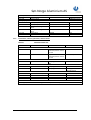
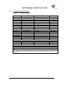
Sør-Norge Aluminium AS
Topic
1 – Purchasing terms
Specification
Publisher Unit
Document No. :
2.3 – Electro Technical Specification
TEK
Date: 06.12.2015
2.3
Revision No. 8.3
by
Torstein Fykse
Valid From: 07.12.2015
Table of Contents:
1.
2.
3.
4.
5.
GENERAL INFORMATION ABOUT BUYER’S ELECTRICAL INSTALLATION ................................. 2
NORWEGIAN REGULATIONS, DIRECTIVES, AND PARTICULAR REQUIREMENTS ......................... 3
WORKMANSHIP REQUIREMENTS .......................................................................... 5
REQUIREMENTS FOR DOCUMENTATION AND TRAINING .............................................. 13
BUYER’S STANDARD (MATERIAL LIST) ................................................................... 16
Buyer in this document is Sør-Norge Aluminium AS.
2.3 Electro technical specification rev 8.3
Side 1 av 24
Sør-Norge Aluminium AS
1.
1.1
GENERAL INFORMATION ABOUT BUYER’S ELECTRICAL INSTALLATION
High Voltage Installation
300kV.
The Main Supply for Buyer has a voltage of 300kV which is supplied from the central power grid.
The central power grid consists of two lines from Blåfalli Switching Station and a subsea cable
from Stord.
24kV.
The unregulated supply has a voltage of 24kV. This supplies the rectifier and the regulating
transformers. The output to SKL/KE is also connected here. The neutral point is insulated.
Maximum Ik is 31.5kA.
Phase Compensating
2 ea. capacitor batteries of 65MVAr are connected to 24kV unregulated distributions.
The capacitor batteries are switched in through 2 steps. When connecting, powerful switching
transients occur, in particular at the 400V level.
20kV.
The general plant supply has a voltage of 20kV, which normally is supplied from one of two
30MVA regulating transformers. The neutral point is insulated.
The Buyer’s transformer stations are supplied with regular 20kV via ring cables from the plant
supply in 20kV buildings.
The Maximum Ik for 20kV in the transformer station is 12kA.
Short circuit yield can be stated for each item on request from the Buyer’s electro department.
1.2
Low Voltage Installations
There are low voltage switchboards in the transformer stations which are supplied from
distribution transformers with a ratio of 20/0.400 kV or 20/0.690kV.
In general, 400V is used as distribution system (TNCS-System) for motors and other 3-phase
loads. 230V direct connection between Phase and N is used for lighting.
As an exception, 690V is used for larger motors and heating installations.
Control voltage (usually 230V AC) is supplied by a control power transformer (secondary side).
The control power transformer (primary side) is connected to 400v (between two phases).
Ground fault monitoring shall be installed on the 230V side when using control power
transformers. For PLC installations, etc., a ground fault alarm shall be presented via the control
system. For smaller installations, a signal lamp indicating ground faults can be installed in the
cabinet door.
For local fault message/alarm, the following system is used:
1. Fault present: Blinking red light, possibly also an acoustic alarm.
2. Alarm deactivated: Continuous red light.
3. Fault removed : Light off
2.3 Electro technical specification rev 8.3
Side 2 av 24
Sør-Norge Aluminium AS
For some installations, transferring some or common alarms to the gate guard is also desirable.
This can be done in the current system or agreed separately.
Buyer’s rectifier installation for electrolysis produces some overharmonic oscillations back to the
power grid.
Short circuit performance at the secondary side of the distribution transformer is in the range of
30kA. This can be stated separately for each point on request from the Buyer’s electro
department.
2.
NORWEGIAN REGULATIONS, DIRECTIVES, AND PARTICULAR REQUIREMENTS
2.1
General.
All assembly and installation shall be performed in accordance with current publications from
DSB:
Regulation on safety at work on and operating electrical installations, with instructions. (FSE)
Regulation on Electrical Low Voltage Installations, with instructions.
Regulations on Electrical Supply Installations. (FEF)
Regulations on qualifications for electrical professionals, with instructions. (FKE)
Before the work commences, Seller shall send a message to the Buyer’s expert manager of
operations.
After delivery, the installation shall be CE-marked in accordance with current directives.
- Machine Directive
- Low Voltage Directive
- EMC Directive
Plants and products shall be delivered with the conformity declaration. The necessary verification
documents shall be delivered with the conformity declaration. Ref. NEK 400-6.
Unless other written agreements have been made, all material shall be delivered in accordance
with the Buyer’s standard (item 5).
If the work has been performed in conflict with current regulations or Buyer’s specifications, the
error must be corrected. Seller shall cover all costs in connection with correcting such errors.
2.2
FIRE PROOFING OF CABLE PENETRATIONS AND SECTIONING
2.2.1
Approved fire proofing materials shall be used for fire proofing.
Furthermore, the proofing shall be of the same fire class as the part of the building where the
proofing is being done, when nothing else is prescribed.
2.2.2
Cable Routing.
Cable trays/bridges shall be completed in front of the penetration to insure good proofing and
access.
2.2.3
Penetrations for piping and ventilation.
Seller will clarify how penetrations will be proofed.
Joint foam or building foam must not be used.
2.3 Electro technical specification rev 8.3
Side 3 av 24
Sør-Norge Aluminium AS
2.2.4
Marking.
The places where the proofing are done shall be clearly marked in accordance with instructions
from Buyer’s officer in charge.
These shall be marked with information about the fire proofing company and the date of the fire
proofing.
2.3
PAINT WORK, CORROSION PROTECTION, ETC.
2.3.1
This shall be performed in accordance with Specification for surface treatment Part 2.7.
2.3.1.1 Objective.
The norm has been set to obtain a consistent and correct treatment in terms of quality of the
surfaces of aluminum and steel constructions. The implemented systems will cover various
environments and usage areas and any deviations from the norm shall be agreed separately.
2.3.1.2 General.
Buyer will, when necessary, specify the painting system in his inquiry. The products of the
specified manufacturers shall be used unless otherwise described or agreed in writing
beforehand.
2.3.1.3 Standards.
Pre treatment
Chemical purity
Surface texture
Adhesion test
-
ISO 8501-1
ISO 8502-1 to 4
ISO 8503-1 Ry 2 – 3
ISO 4624
2.3.1.4 Deviations.
Deviations from the norm must be approved in writing from Buyer.
2.3.1.5 Source.
This description is, for the most part, worked out in accordance with Norsk Hydro’s norm EH-015,
and Buyer’s specification for surface treatment Part 2.7
2.3.1.6 Abbreviations.
PUR
ISO
TFT
YL
RAL
-
Polyurethane
International Standardizing Organization
Dry Film Thickness indicated in µm. (micron)
Air quality and supply in the work environment
International color code. Buyer’s specification for surface treatment
Part 2.7
2.3 Electro technical specification rev 8.3
Side 4 av 24
Sør-Norge Aluminium AS
3.
WORKMANSHIP REQUIREMENTS
3.1
HIGH VOLTAGE.
3.1.1
Contactor Cabinet, Control Cabinet, Measuring Fields, etc.
Description in item 3.2.1. with under items shall be followed unless otherwise agreed.
3.1.2
High Voltage Equipment
3.1.2.1 Bus Bars
At delivery of bus bar installations, these shall be adapted to existing grounding systems, and
delivered with appropriate grounding appliances.
Due to the high current in the rail systems, the nuts and bolts on the rails shall be made from
stainless steel A2 80 quality grade.
3.1.2.2 High voltage cabinets / Power Switches / Knife Disconnectors.
Compact cabinets or cabinets for switch trolleys may be used in transformer stations. Short
circuit current for the cabinet shall be minimum Ik=12.5kA. The switches shall be rated In=630A.
In the main power supply installation (24kV), cabinets for switches mounted on switch trolleys
with short circuit current of minimum Ik=31.5kA, and switches for 2500A are required.
In 20kV buildings, switches for regulated 20kV distributions (20kV) shall have minimum short
circuit current of Ik=12.5kA and In=1250A, or as agreed otherwise.
Buyer is planning on using SF6 power switches.
3.1.2.3 High Voltage Cables.
All high voltage cables shall be rated at 24kV or as agreed otherwise.
3.1.2.4 End Termination.
Here it may be differentiated between indoor and outdoor types, depending on where the
installation is mounted. Conventional end terminations and terminations of a ”touch proof” type
can be used indoors.
3.1.2.5 Transformers.
To be produced and delivered in accordance with IEC 60076-1 and IEC 60076-2.
All distribution transformers shall have oil insulation, preferably with environment friendly
oil/vegetable oil. Data sheet for the transformer oil shall be referenced in all offers to Buyer.
Accessories shall be agreed for each case. Such accessories shall monitor oil temperature, gas
pressure and oil level.
All transformers shall be delivered with swiveling wheels.
The temperature indicator on the transformer shall be readable from the inspection point. All
transformers shall be mounted with signs indicating all substantial transformer performances,
volume and weights. All signs and indicators shall be readable when the transformer is in
operation, without endangering the personnel.
For distribution transformers that do not have standard performance, and power transformers
rated at over 1600kVA, a special agreement is required.
2.3 Electro technical specification rev 8.3
Side 5 av 24
Sør-Norge Aluminium AS
Short circuit performance at the secondary side of the distribution transformer is in the range of
30kA. This can be stated separately for each point on request from Buyer’s electro department.
Connection points for grounding devices shall be installed in transformer cells.
3.1.3
Installation and Mounting of High Voltage Supply Installations.
Installation plan and test plan shall be presented for Buyer in a reasonable time before the
installation commences.
3.1.3.1 Bus Bars.
The torque shall be documented for all screw connections. The standard being used shall be
documented. On the plant, every connection shall be “checked off”.
If specified, documented resistance measurements shall be performed for bus bar deliveries in
addition to insulation measurements. Place mounted bars and pre-fabricated, insulated bus bars
shall be tested with 50kV for one minute.
3.1.3.2 High voltage cabinets / Power Switches / Knife Disconnectors.
Simplified user manual in Norwegian for switches and guards shall be presented before the
installation is powered up.
For all high voltage areas, there shall be signs mounted which show manufacturer, year of
production, performance, voltage and short circuit currents. A short user instruction shall also be
placed on the front of installed devices. All text shall be in Norwegian.
3.1.3.3 Cable Laying, High Voltage Cables
High voltage cables must be attached with approved cable fasteners and the laying shall be
documented.
Calculations regarding short circuit power and dimensioning of fastenings shall be presented to
Buyer.
When feasible, the high voltage cables shall be routed on separate cable trays/paths. In case high
voltage cables are routed on the same cable tray as low voltage cables, Buyer shall be contacted,
and the distance between the cable paths shall be made in accordance with regulations.
3.1.3.4 Termination and Connection
Crimping of cable lugs/connection sleeves on aluminum cables shall be applied with ”dorpress”.
Terminations and joints on Cu cables shall be applied with hexagonal press.
Buyer shall verify terminations and joints before mounting cable lugs when cables are made
ready for mounting, and with jacket cut. Each joint/termination shall be documented in writing.
End terminations shall be carried out in accordance with the manufacturer’s standard mounting
instructions.
Thermotape/thermos strips shall be mounted on all end terminations. Temp. range: 70-110°C.
There shall be a marking that shows the mounting date under each end termination.
Cable lugs shall be tightened with the torque stated in the end documentation.
3.1.3.5 Transformers and Mounting.
Measuring transformers for high voltage shall, to the extent possible, be adapted to the
maximum current load for the transformers.
For transformers with output up to 800 kVA, the measuring transformer shall have a ratio of 30/5
A. For transformers up to 1600kVA, current transformers with a ratio of 50/5 A shall be used. In
general, distribution transformers larger than 1600kVA shall not be installed.
Details are required on the grounding of transformers in transformer cells. There shall be a
minimum of 2 secondary windings (one for measuring and one for protection). The class must be
agreed in each case. Measuring transformers shall be grounded and documented in accordance
with the manufacturer’s specifications.
2.3 Electro technical specification rev 8.3
Side 6 av 24
Sør-Norge Aluminium AS
3.1.3.6 Requirements for Security System and Locking
All completed high voltage components or installations shall be lockable. Officer in charge shall
approve the arrangement.
LOTO (Lock Out Tag Out) is a security system for removing all energy in machines and to prevent
accidental switch-on/start up of machines. All installations shall be arranged for such a system.
Buyer’s officer in charge shall be contacted for approval of the design.
3.1.4
Transport and Packing
Transport and packing of high voltage components shall have packaging made from durable
materials. Components that are delivered in larger crates shall be individually secured, and be
surrounded by shock absorbing material when necessary. Components that are not moisture
proof shall be packed accordingly. If the components contain any oil, the oil MSDS shall be
included in the delivery documents.
3.2
LOW VOLTAGE
3.2.1
Distribution Boards, Contactor Cabinets, etc.
In addition to Buyer’s specifications, NEK-EN-60439 applies.
Short circuit performance at the secondary side of the distribution transformer is in the range of
30kA. This can be stated separately for each point on request from Buyer’s electro department.
3.2.1.1 Cabinet types – Density – Color, etc.
380V distribution boards in transformer stations shall be equipped with ABB “Slim-line” fuses
unless stated otherwise.
Regarding other cabinet types, density requirements, color, etc. see Buyer’s standard unless
otherwise agreed (see item 5.4.).
3.2.1.2 Room for 15% expansion
After the cabinets are installed, and the installation is commissioned, there shall be free room for
at least 15% expansion. This is applicable to room for components, extra cable glands and
connection strips. Power supply and control current transformers shall be dimensioned for 15%
extra load.
3.2.1.3 Grounding – Neutral Conductor in Distributions
All distribution cabinets shall have separate bars / connection clamps for grounding and neutral
conductor. Ground and neutral bar shall be mounted close to the output clamps. They shall be
readily accessible after the cables are mounted. Each cable connection shall have their own
connection clamp both to ground and to neutral conductor bar.
All control cabinets shall have grounding bars at the cable entry point to the cabinet. All
groundings and shields on ingoing and outgoing cables shall be connected to this bar. It is
important that the ground conductor on the cables inside the cabinet is as short as possible to
limit EMC problems.
2.3 Electro technical specification rev 8.3
Side 7 av 24
Sør-Norge Aluminium AS
3.2.1.4 Connection and Marking of Cables
The main rule is that output cables are connected to terminal strips. Other systems shall be
agreed upon with Buyer. Only one conductor in each terminal.
The cables shall be marked with the same cable number on both ends. The conductors shall be
marked with terminal numbers. The cables shall have sufficient stress relief at the entry point of
connection boxes with the aid of cable glands, or other standardized systems. Cable marking
system shall be agreed upon with Buyer.
Cable lugs and Connection Crimping of cable lugs/connection sleeves on aluminum cables shall
be applied with ”dorpress”. Terminations and joints on Cu-cables shall be applied with hexagonal
press. Cable lugs shall be tightened with the torque stated in the final documentation.
3.2.1.5 Placing and mounting of terminal strips
Terminal strips that are closer to the floor than 50 cm shall be mounted at an angle of 60°.
Terminal strips shall be numbered consecutively from left to right or from top to bottom.
Terminals in measurement loops shall be measuring terminals (see item 5.2.7.35). Measurement
terminals shall be equipped with sockets for 4 mm banana plugs.
Different voltage levels shall have their own terminal strips. This is also applicable for strange
voltages even where only one or two terminal strips are in question.
3.2.1.6 Cable Connections Control Power
Cable connections for control power shall be multistranded, with a minimum cross section of
0.75 mm². The conductors shall be placed in plastic conduits. The conductor ends shall have
connection sleeves at the connection point. The conductor ends shall be marked with marking
sleeves that state their respective component’s connection number, i.e., on relay/contactors: A1A2, 13-14 etc. This ensures easy replacement of components without having to use a diagram.
Connection sleeves with plastic tabs shall not be used as marking sleeves. For internal
connections, there shall not be more than two conductors in each connection point on
components and one conductor in terminal strips.
3.2.1.7 Cable Conduits – Free Capacity
The plastic conduits shall not be filled more than 75% when the installation is ready for
commissioning. Whenever possible, the control power conductors shall be kept separate from
the main power. A plastic hose shall be used for the protection of connections between cabinet
and cabinet doors (RITTAL or similar).
3.2.1.8 Component Mounting and Marking
All components shall be mounted in such a manner that they can be readily replaced. They shall
be marked with position numbers in accordance with the drawings. Black letters on a white
background shall be used on signs/mark. The signs shall be mounted in the bottom of the
cabinet, or special marking bars, - not on the component or the plastic conduits. Contacts and
relays can also be marked with a ”light proof” marker on the marking signs from the factory. PLC
I/O shall be marked on the front with text.
3.2.1.9 Operation Signs Shall Have Norwegian Text
Operation signs shall have Norwegian text.
3.2.1.10 Operation Order
a) Increase, from bottom to top, or from left to right.
b) Reduce, counter clockwise from top to bottom, or from right to left.
c) Start/stop button: Location of start/stop buttons should preferably be vertical. Start button
on top and stop button at the bottom. If the start/stop buttons are placed horizontally, the
2.3 Electro technical specification rev 8.3
Side 8 av 24
Sør-Norge Aluminium AS
start button shall be placed on the right-hand side and the stop button on the left-hand side.
For normal operations, all switch levers shall be in vertical and middle positions, respectively.
3.2.1.11 Color Requirements for Indicator Lights and LEDs.
Signal Lights
RED
Alarm
GREEN
Ready for start
WHITE
Operation Light
Push Buttons
RED
Stop or Off
GREEN
Start or On
For others, in accordance with the current IEC-norm.
The Supply Voltage to signal lights/LED indicators shall be 24V.
For installations with more than 5 signal lights/LEDs, there shall be controls for lamp testing.
Incandescent lamps shall not be used.
3.2.1.12 Requirements for Conductor and Cable Colors
Neutral Conductor shall, in accordance with regulations, have a light blue color.
The Neutral Conductor shall always have the same insulation as the phase conductor. (Cu-shield
shall never be used as Neutral Conductor). N and PE shall only be connected (with a detachable
connection piece) in the first distribution.
The ground conductor shall be colored yellow/green in accordance with regulations. No other
connections shall be colored yellow or green.
PEN-conductors shall be colored yellow/green/blue.
In cabinets, black conductors shall be used for (L1, L2, and L3) outer conductors. Control power
conductors, 230V AC on the secondary side of the control power transformer shall be colored
red. For 220V DC, the color violet shall be used (TP 90). 24V DC is performed with blue cable. For
power transformer loops, the cross section must be adapted to Buyer’s requirement for loop
resistance. Minimum cross section is 2.5 mm². Black conductors are used both for power and
voltage transformer loops.
Conductors with strange voltages and voltage from other installations shall be colored orange.
When using TP-conductors, reduced cross sections are not acceptable for what concerns
conductivity and temperature. PN and TP are regarded as being equal, and shall be mounted in
accordance with regulations as PN conductors. For machine installations, either 24V DC or 230V
AC control power is used. For 24V DC control power, the negative pole shall be connected to
ground.
Voltage Level
24V DC control power
230V AC control power, insulated
220V DC
Cable Color
Blue
Red
Violet
Power measurement
Voltage measurement
400V phase voltage
690V phase voltage
Strange voltage
Neutral conductor
Black
Black
Black
Black
Orange
Light Blue
2.3 Electro technical specification rev 8.3
Note
Control installations in 20kV
building
Normally up to 5A
Normally 100V
Independent of voltage level
Side 9 av 24
Sør-Norge Aluminium AS
3.2.1.13 IP Class Protection
All voltage-carrying parts must be protected against accidental touching, minimum IP 20.
Buyer shall agree on protection classes for surroundings and environment in case of doubt.
3.2.1.14 Cabinet Locks
In locked rooms with distribution boards, all cabinets shall be able to be opened or closed
without using keys or special tools. Outside of locked rooms with distribution boards, the
cabinets shall be opened using keys only.
3.2.1.15 Fuses
Automatic fuses are used up to and including 63 A (C-char). Automatic circuit breakers for
important control power circuits shall be equipped with signal contacts. For larger loads, load
disconnectors or power switches shall be used. Automatic circuit breakers or melting fuses shall
not be used for 24V DC supply to PLC inputs/outputs. See next section.
3.2.1.16 PLC Controls
All PLC controls shall have the possibility for Profibus connections.
Controls, including PLC, shall preferably be placed in separate cabinets with their own power
supply, etc. The PLC should be mounted on a carrier plate. 24V DC supply to PLC inputs/outputs
shall be guarded by an electronic over-current guard. Signals from over-current guards shall be
connected to alarm/indicator lights.
3.2.1.17 Lights in Cabinets
As a main rule, fluorescent lights with door switches shall be mounted in tall cabinets (2m or
taller). Other systems shall be agreed with Buyer. The installation in the cabinets shall be
connected to special, separate terminals, which are intended for 230V strange voltage.
3.2.1.18 Energy measurement
Energy measurement shall be delivered with machines. Shall be agreed with Buyer.
3.2.2
Installation and Mounting on Machines
3.2.2.1 Norwegian Regulations for Electrical Low Voltage Installations, including Instructions must be
followed when using NEK-400. (EN 60364)
3.2.2.2 Machines - Control
Electrical cabinets for machines shall be placed in a separate, electrical room. Input signals to
PLCs placed on the machine itself shall be connected to distributed I/O units on the machine.
ET200S on Profibus DP and/or Asi bus shall be used as distributed I/O.
Motor starter equipment shall be placed in electrical cabinets in the electrical room and be
controlled from output cards on the PLC. 400V and 690V cables from motors and other power
consumers shall be routed directly to the contactor cabinet.
The control of solenoid valves for air and hydraulics shall be carried out with ET200S units in
cabinets next to the cabinets for solenoid valves. Exceptions from this may be allowed where
there are few valves and a short distance to the electrical cabinets. This must be agreed with the
Officer in charge.
The positioning of the machines shall be performed with laser. The laser shall be mounted on the
fixed part. When laser cannot be used, absolute sensors connected to Profibus DP shall be used.
2.3 Electro technical specification rev 8.3
Side 10 av 24
Sør-Norge Aluminium AS
3.2.2.3 Requirements for Safety System
All machines shall be manufactured in accordance with the Machine directive. Buyer shall
approve SIL-classification.
LOTO (Lock Out Tag Out) is a security system for removing all energy in machines and to prevent
accidental switch-on/startup of machines. All installations shall be arranged for such a system.
Buyer’s officer in charge shall be contacted for approval of the design.
3.2.2.4 Placement of Components
Each of the components that are part of the control system shall have a favorable position for
replacement, maintenance, and to avoid mechanical damage. Solenoid valves shall preferably be
mounted together in special cabinets, control voltage, preferably 24V DC, or as agreed upon.
Manufacturer, see item 5.2.6. Solenoid valves shall not be placed in the electrical cabinets. All
equipment must be mounted and protected against oil spills, water, snow and frost.
3.2.2.5 Marking of Components and Equipment
All equipment shall be clearly marked with position no. in accordance with the drawings.
Engraved signs with black letters on a white background shall be used. The signs shall not be
placed on the component, but on a mounting plate or construction part that is not being
removed during normal maintenance work.
3.2.2.6 Ventilation Installations
All controls are agreed upon (see item 5.2.9).
Electrical heating batteries shall be designed as convection heat batteries, not using radiation
heat.
3.2.2.7 Soft Starters
Soft starters shall be used instead of star/triangle start. Soft starters shall be used for motor drive
on conveyors / chain belts. For installations where frequent motor start/stops because of energy
conservation is desired, soft starters shall be installed.
3.2.3
Cable Routing - General
3.2.3.1 Cable Trays
Cable trays in aluminum shall be used or as otherwise agreed. Routing choices shall be agreed for
each single case. When the installation is being commissioned, there shall be 15% free room on
the cable trays.
3.2.3.2 Cable Fastening - Strips
Outdoors, in pot-rooms and Foundry, acid proof steel strips shall be used for cable fastening.
Plastic strips made from UV proof material is otherwise accepted. This is also applicable for
fastening of cable marks.
3.2.3.3 Marking of Cables.
All cables shall be marked in both ends with their respective cable numbers in accordance with
drawings/cable lists.
3.2.3.4 Cable Dimensions.
It is Seller’s responsibility to choose correct cable dimensions according to load, short circuit
performance, elongation ratio, and voltage drops. Calculations of short-circuit and dimensioning
shall be documented in writing. Unless otherwise agreed upon, Febdok shall be used. Febdok
database files are to be delivered electronically with all files open for editing.
2.3 Electro technical specification rev 8.3
Side 11 av 24
Sør-Norge Aluminium AS
3.2.3.5 Capacity of Supply Cables.
Cables shall be delivered in accordance with item 5.2.2. Supply cables/power cables shall be
dimensioned for minimum 20% over-capacity. Different voltage levels shall normally not be
present in the same cable. Any deviations from this shall be agreed with Buyer’s electro
department beforehand.
3.2.3.6 Cable Routing on Trays.
Power and signal cables on the same tray shall, when possible, be placed in separate paths.
3.2.3.7 Cable to Machines
For machines, cables of type PFSP or similar, shall normally be used.
Motor cables shall be of type PFSP or similar. This is a cable that is shielded and has an operation
voltage of 1kV.
2.3 Electro technical specification rev 8.3
Side 12 av 24
Sør-Norge Aluminium AS
4.
REQUIREMENTS FOR DOCUMENTATION AND TRAINING
4.1
Drawings and Descriptions
All drawings and technical descriptions shall have Norwegian or English text. Operations and
maintenance instructions, etc. shall have Norwegian text.
Drawing basis and documentation, in addition to marking of installations and components shall
be in accordance with NEK 144. (EN 60617 / EN 61346)
Electrical components in machine installations shall be marked with a letter for the type of
component used and also be marked with a number for the side and power path where it can be
found on the electrical drawings.
4.2
For each installation the following documentation shall be delivered:
4.2.1
Installation Drawings
Can be prepared in standard formats A3 to A0. The drawings shall show the position of electric
components, equipment and cable connections in plants/buildings. The numbering and marking
must be consistent with the associated diagrams and drawing basis.
4.2.2
Arrangement Drawings
Can be prepared in format A4 to A1. The drawing(s) shall show internal construction, placement
and marking of equipment in distribution boards, consoles, etc.
4.2.3
One-Line Diagram
Can be delivered in the following formats; A4 and A3. The drawing shall represent one single
one-line diagram without control current. One-line diagrams for transformer stations
(distribution stations) shall be delivered, as well as for installations with voltages above 400V.
4.2.4
Current Flow Diagram
The following formats are accepted: A4 and A3. The drawings shall be divided into:
a)
b)
c)
d)
Main Current
Control Current
Alarm, error messages
Electrical schematics/hydraulic diagrams, i.e. hydraulic diagrams with electrical components
(solenoid valves, end switches, etc.) clearly marked with reference to electrical schematics.
e) Electrical schematics/pneumatic diagrams, similar to electrical schematics/hydraulic
diagrams.
f) Diagrams for instruments, control and electronics.
g) Associated connection tables and terminal lists.
2.3 Electro technical specification rev 8.3
Side 13 av 24
Sør-Norge Aluminium AS
4.2.5
Drawings, etc., for PLC/Computer Controlled Plants
In addition to the mentioned current flow diagram, diagrams of inputs/outputs for PLC units and
an overview of used card types and outputs/inputs must be included. Furthermore, a program
for the concerned PLS-system is delivered. The PLC programs shall be developed on PC, program
version in accordance with agreement.
The program shall be transparent so that troubleshooting installations (processes) is made as
simple as possible. Both program structure and program must be documented in Norwegian or
English.
After the installation is commissioned, Seller is responsible for providing Buyer with the copy
latest program version.
4.2.6
Apparatus List (parts list)
Format: A4
In the apparatus list, all the electrical and electrically controlled apparatuses in the installation
shall be included. The list shall include:
a)
b)
c)
d)
e)
f)
4.2.7
Quantity
Marking/Position
Manufacturer
Description, type, ordering data
Reference to current flow diagram
Notes with distributor/Seller
Cable List
Format: A4
In the list, all cables that are part of the group or installation in question shall be included. The
cable list shall include the following:
a)
b)
c)
d)
e)
f)
g)
h)
i)
4.2.8
Connection from (denomination / reference) in accordance with IEC norm)
Connection to (denomination / reference) in accordance with IEC norm)
Number of conductors
Conductor cross section
Type
Length
Cable no.
Note
Voltage Level
Spare Parts.
The offer shall include necessary spare parts and prices. In the general offer on spare parts for
the installation, electrical components shall also be included. These shall be listed with
references as for the parts list, item 4.2.6.
Any spare parts that are ordered in the main order shall be available when a plant is
commissioned.
The spare parts list must include a complete type denomination and manufacturer.
2.3 Electro technical specification rev 8.3
Side 14 av 24
Sør-Norge Aluminium AS
4.2.9
Description.
For all plants, the following descriptions shall be included before commissioning:
a) Technical description of the installation’s function theory with reference to the electrical
documentation
b) Functional descriptions and technical documentation on the components used
c) Maintenance instructions for the same components shall be specified in a list with intervals.
d) The necessary documents for verification in accordance with NEK 400-6.
4.2.10
Drawing Copies.
2 sets of drawing copies shall be delivered to Buyer within a reasonable time frame before the
installation starts. 1 set with updated drawings shall be available to Buyer (at the plant) at all
times, from the start of installation until final documentation has been delivered.
4.2.11
Updated Drawings – AutoCad.
Seller of the installation shall deliver 2 sets of updated drawing copies with dates and signatures
after commissioning. The drawings and documents shall also be delivered electronically in the
AUTOCAD format (DWG format). Each sheet as one file. For drawing no. XXXXX sheet 1, the file
name shall be XXXXX-1.DWG.
4.2.12
Deadline for Delivery of Drawing Documentation
Unless otherwise agreed, the As Built-documentation shall be delivered to Buyer no later than
one month after plant commissioning.
4.2.13
Requirements for Storage of Drawing Copies
Copies of the original drawings, as built, shall be available from Seller for at least 10 years.
4.2.14
Professional Workmanship on Installations.
Buyer’s approval of presented drawings and documentations does not excuse Seller from the
responsibility to deliver a professionally executed installation, and to follow current regulations
and Buyer’s specifications.
4.2.15
Copying.
All copying expenses as mentioned in item 4.2.10 and 4.2.11 will be charged to Seller.
4.2.16
Assignment of Drawing and Object nos.
Seller shall contact Buyer to have Buyer’s drawing numbers and object numbers assigned. Both
text files and drawings shall be registered with Buyer’s drawing numbers. The drawing numbers
and the sheet numbers shall be unique.
4.3
Training
4.3.1
A training plan shall be prepared for operation and maintenance. The training plan from Seller
shall be in place before commissioning, testing, and start of operations for machine or
installation. The training plan shall be approved by Buyer and shall cover maintenance and
operation.
2.3 Electro technical specification rev 8.3
Side 15 av 24
Sør-Norge Aluminium AS
5.
BUYER’S STANDARD (MATERIAL LIST)
5.1
High Voltage
5.1.1
Apparatus Cabinets and Switches
Material
5.2.1.1
5.2.1.2
5.2.1.3
5.1.2
High Voltage Switch Cabinet
ABB, Schneider, Siemens; in accordance with agreement
Load Switch
Air insulated or as an SF6 switch
Power Switch
SF6 switch, fixed in combination with disconnecting switch, or on a switch trolley.
Cable and end terminations
Material
5.1.2.1
5.1.2.2
5.1.3
MANUFACTURER TYPE
MANUFACTURER TYPE
24kV Cable for Outdoor Installation
TSLE Al or Cu, twisted 1-conductor. Pirelli, Nexans, General Electric. Others in
accordance with agreement
24kV End Terminations and Joints
Elastimold, Raychem. Types in accordance with agreement
Transformer
Material
5.1.3.1
5.1.3.2
5.1.3.3
MANUFACTURER TYPE
Power transformers
Agreed with Buyer
Special Transformers
Agreed with Buyer
Distribution Transformers
Standard outputs up to and including 1600kVA. Voltage ratio 20000/400V or /690V, connection Dyn5. ABB, France Trafo, Møre Trafo, Siemens, Norsk
Transformator
2.3 Electro technical specification rev 8.3
Side 16 av 24
Sør-Norge Aluminium AS
5.2
Low Voltage
5.2.1
Fuse Parts
Material
5.2.1.1
5.2.1.2
5.2.1.3
5.2.1.4
5.2.1.10
5.2.1.11
5.2.1.12
5.2.2
MANUFACTURER TYPE
Load Disconnecting Switch
Load disconnecting switch 3NP Siemens AS
Load disconnecting switch SLP, XLP ABB
Load Switch
Load switch 3KL50-3KL61 Siemens AS
High Power Cartridges
High power cartridges 3ND, 3NA Siemens AS
Power switch and engine protection switches
Power switch 3 VF, 3 RV, 3WN Siemens AS
Automatic circuit breakers AC, Residual current circuit breaker 5SU
Automatic circuit breakers for AC 5SY (440V AC) Siemens AS
B and C Characteristic.
Automatic fuses DC
Automatic circuit breakers for DC S 280UC (220V=) ABB Stotz
Electronic protection for 24V DC PLC inputs/outputs.
Siemens Sitop diagnosis module, part no. 6EP1961-2BA00
Cable
Material
MANUFACTURER TYPE
In compliance with Officer in Charge, non-halogenated cables shall be used in some areas.
5.2.2.1
5.2.2.2
5.2.2.3
5.2.2.4
5.2.2.5
Screened house wiring cable
Screened house wiring cable/aluminum sheath PR/IFLI 1.5, 2.5, Odin Kabel, Draka,
Nexans, Tec Con.
Only allowed for installation in offices, mess rooms, etc.
1KV w/shield
1 KV w/shield PFSP/IFSI 1,5, 2,5. Nexans, Tec Con.
Copper cables shall be used up to and including a conductor cross section 35 mm².
If there is a need for cables with a larger power conducting ability, cables with
aluminum conductors may be used.
Flexible Cable
Flexible cables on/for cranes and power chains in accordance with agreement. For
example, Ølflex. Cables to be hauled shall be approved for this use.
Plastic Insulated Conductors
Plastic insulated PN 750V, multiple strands
Only allowed in piped installations and as internal connections in cabinets.
Low current cable – ground and industrial buildings
Low current cable A-09EEBP-45D or IXLI + LIYCY
In ground and industrial buildings.
2.3 Electro technical specification rev 8.3
Side 17 av 24
Sør-Norge Aluminium AS
5.2.2.6
5.2.2.7
5.2.2.8
5.2.2.9
5.2.2.10
5.2.2.11
5.2.3
Extension cables and supply cables for portable apparatus
Rubber cable NMHVO
Plastic insulated conductor – control power 230V AC
Plastic insulated conductor 7) TP 90 violet
Used for control power, 230V AC.
Compensating cable – temperature measurements
Compensating cable PSP type K Gefran
Used for temperature measurements.
Fiber Cable
Fiber cable 62,5 / 125µ. Number of fibers in accordance with agreement
Cable for Data Communication
Cable for data communication Category 5 E
Note!
Cables for data installations and similar, to be agreed with Buyer’s electro
department before ordering.
Motors
5.2.3.1 3 Phase Engines 50 Hz
3 Phase Motors In accordance with agreement
Motors from 22 kW (included) and upwards shall be rated at 400/690 Volt.
Efficiency Class, Degree of Effectivity and Losses shall be stated.
On larger motors, vibration measuring (SPM) shall be installed. When using frequency
converters on larger motors, insulated bearings shall be mounted.
Note! Degree of protection for motors: IP 54
5.2.3.2 Frequency Converters and Soft Starters
Material
5.2.3.1
5.2.3.2
5.2.4
MANUFACTURER TYPE
Frequency Converters
The manufacturers Siemens, ABB and Fuji may be used.
Soft Starters
The manufacturers Siemens and Stadt may be used.
Control cabinets, distribution boards and connection cabinets
Material
5.2.4.1
5.2.4.2
MANUFACTURER TYPE
Terminal box – OUTDOORS
Terminal box (outdoors and in harsh environments) Rose Polyester/Rose
aluminum. GA boxes: RITTAL Boxes/cabinets outdoors and in harsh environments,
degree of protection: IP65
Terminal box/cabinets – INDOORS
Terminal box/cabinets (inside of RITTAL type KL AE RITTAL normal industrial
atmosphere) Boxes/cabinets in normal industrial atmosphere, degree of
protection: IP55
2.3 Electro technical specification rev 8.3
Side 18 av 24
Sør-Norge Aluminium AS
5.2.4.3
Control cabinets – INDOORS
Control cabinets RITTAL type AK, AS, PS, RITTAL ES, TS8, KS
Relay control cabinets, degree of protection: IP55
5.2.4.4
Control cabinets – OUTDOORS
Control cabinets outdoors, to be agreed with Buyer. Acid proof or UV-resistant
synthetic material.
Surface Treatment:
Standard hardened varnish RAL 7032
5.2.5
Contactors, relays, timer relays
Material
POS
Contactors
5.2.5.1
Control relay
5.2.5.5
5.2.5.6
5.2.5.7
5.2.5.8
5.2.5.9
MANUFACTURER TYPE
Material
TYPE
MANUFACTURER
Contactors
SIRIUS 3 RT, 3TF
Siemens AS
Control relay
Control relay (switch contact
for socket PLC-BSC-24DC/21)
Control relay base
3RH
REL-MR-24DC/21 item no.
2961105.
PLC-BSC-24DC/21 part no.
2966016.
OPT-24DC/24DC/2 part no.
2966595
EMG 17-OV-24DC/240AC/3
part no. 2954235
Siemens AS
Phoenix
3 RU11, 3RB10
Siemens AS
3RP
3RP
Siemens AS
Siemens AS
IRD420-D4-2
Bender
Control relay (optical coupler
to base PLC-BSC-24DC/21)
Control relay (optical coupler
24V DC in 230V AC output.
Bimetal relay
5.2.5.10
Bimetal relay
Timer relay
5.2.5.15
Timer relay delayed closing
5.2.5.20
Timer relay delayed opening
Ground fault relay
5.2.5.30
Ground fault relay
Operation Parts
5.2.5.50
Operation Parts
Push Buttons
5.2.5.51
Push Buttons
Signal Lamps
5.2.5.53
Signal lamps/LED
Switches
5.2.5.55
Switches
Accessories
5.2.5.57
Accessories
Encapsulated operation parts
5.2.5.58
Encapsulated operation
parts
2.3 Electro technical specification rev 8.3
Phoenix
Phoenix
Phoenix
Dim.: Ø 22 mm
3SB3
Siemens AS
Siemens AS
Siemens AS
Siemens AS
Siemens AS
Side 19 av 24
Sør-Norge Aluminium AS
Service/LOTO switches
5.2.5.59
Service switch
5.2.5.60
Service switch
Safety Equipment
5.2.5.61
Safety relay
5.2.5.62
Safety relay
5.2.5.63
Safety switch for gates and
doors
5.2.5.64
Safety switch for gates and
doors
5.2.5.65
Light barrier
5.2.5.66
Light barrier
5.2.6
3LD
Siemens AS
ABB/Phillip Hauge
Preventa XPS-AF
PNOZmulti
AZ335-12zk-M20
Telemecanique
Pilz
Schmersal
XCS
Telemecanique
M2000
MSL
Sick
Sick
End switches, initiators, photocells, solenoid valves
Material
MANUFACTURER TYPE
POS
End switches
5.2.6.1
Material
TYPE
MANUFACTURER
End switches
Siemens AS
5.2.6.5
End switches
Only to be used where
photocell/initiator cannot
be used
Only to be used where
photocell/initiator cannot
be used
Initiators
5.2.6.10
Initiators
With plug connection
M12
Turck
Photocells
5.2.6.11
5.2.6.14
Photocells
Photocells
With plug connection M12
With plug connection M12
Solenoid valves
5.2.6.15
Solenoid valves - Hydraulic
5.2.6.16
Solenoid valve - Pneumatic
Ultrasound sensor
5.2.6.17
Ultrasound sensor
Telemecanique
Sick/Telco
Datalogic/
Telemecanique
Bosch Rexroth
Bosch Rexroth
RU30-M30-APBX-H1141
Turck
Other types/manufacturers shall be agreed with Buyer’s electro department.
2.3 Electro technical specification rev 8.3
Side 20 av 24
Sør-Norge Aluminium AS
5.2.7
Terminal strips, connection parts, etc.
Material
MANUFACTURER TYPE
POS
Material
TYPE
Terminal strips
5.2.7.1
Terminal strips
WDU 2.5/35
5.2.7.2
Terminal strips
WDU 4/35
5.2.7.3
Terminal strips
WDU 6/35
5.2.7.4
Terminal strips
WDU 10/35
5.2.7.5
Terminal strips
WDU 16/35
5.2.7.6
Terminal strips
WDU 35/35
5.2.7.7
5.2.7.8
Terminal strips
WDU 70/95
5.2.7.15 (*)
Terminal strips
WDK 2.5. 800V
Grounding terminals
5.2.7.16
Grounding terminals
WPE 2.5/35
5.2.7.17
Grounding terminals
WPE 4/35
5.2.7.18
Grounding terminals
WPE 10/35
5.2.7.19
Grounding terminals
WPE 16/35
Zero terminals
5.2.7.25
Zero terminals
NT 2.5/35
5.2.7.26
Zero terminals
NT 6/35
Measuring terminals
5.2.7.35
Measuring terminals w/4mm socket
Current
LT WTL 6/2
Voltage
LT WTL 6/1
Mounting rail
5.2.7.40
Mounting rail
TS 35x15
MANUFACTURER
Weidemüller
Weidemüller
Weidemüller
Weidemüller
Weidemüller
Weidemüller
Weidemüller
Weidemüller
Weidemüller
Weidemüller
Weidemüller
Weidemüller
Weidemüller
Weidemüller
Weidemüller
Weidemüller
Weidemüller
(*) Only allowed in PLC cabinets
All terminal strips for mounting rail TS 35
Any other terminal strip types shall be agreed with Buyer in reasonable time before installation
commences.
2.3 Electro technical specification rev 8.3
Side 21 av 24
Sør-Norge Aluminium AS
5.2.8
Lighting Equipment
Material
MANUFACTURER TYPE
POS
Material
Street/Road Lighting
5.2.8.1
Armature
Lighting for industry halls
5.2.8.2
Armature
Lighting for workshops and similar
5.2.8.3
Armature
Lighting outdoors and in harsh atmospheres
5.2.8.5
Armature
Lighting for offices and similar
5.2.8.5
Armature
TYPE
MANUFACTURER
To be agreed with Buyer
S
To be agreed with Buyer
To be agreed with Buyer
To be agreed with Buyer
To be agreed with Buyer
Note!
For larger lighting installations, light calculations and choice of armature must be submitted to Buyer
for approval.
5.2.9
Programmable Controls
Material
5.2.9.1
5.2.9.2
5.2.9.3
MANUFACTURER TYPE
PLC
Programmable controls, PLC.
PLC - Manufacturer
The plants shall be controlled by PLC. The PLC shall be manufactured by Siemens
Simatic S7-300 series or S7-400 series.
PLC
The PLC shall have free memory and I/O capacity of minimum 15% for future
expansions. Both S7-300 and S7-400 series shall use S7-300 I/O.
I/O cards shall be of the following types:
DIGITAL Input card 6ES7 321-1BH02-OAAO
ANALOG Input card 6ES7 331-7KF02-OABO
ANALOG Output card 6ES7 332-5HD01-OABO
DIGITAL Output card 6ES7 322-1BHO1-OAAO 0.5A
DIGITAL Output card 6ES7 322-1BF01-OAAO 2A
CPUs shall be of the following types:
CPU 313C 6ES7313-5BE01-0AB0
CPU313C-2DP 6ES7313-6CE01-0AB0
CPU 314 6ES7314-1AF10-0AB0
CPU315-2DP 6ES7315-2AG10-0AB0
CPU317F-2DP 6ES7317-6FF00-0AB0
CPU414-2 6ES7414-2XG04-0AB0
CPU416-2 6ES7416-2XK04-0AB0
Use of other cards shall be in agreement with Buyer.
2.3 Electro technical specification rev 8.3
Side 22 av 24
Sør-Norge Aluminium AS
5.2.9.4
PLC – Distributed I/O
Electrical cabinets for machines shall be placed in a separate electrical room. Input
signals to PLCs placed on the machine itself shall be connected to distributed I/O
units on the machine. ET200S on Profibus DP and/or Asi bus shall be used as
distributed I/O.
The control of solenoid valves for air and hydraulics shall be performed with ET200S
units in cabinets next to the solenoid valve cabinets. Exceptions from this may be
allowed where there are few valves and a short distance to the electrical cabinets.
This must be agreed with Buyer’s officer in charge.
Motor starter equipment shall be placed in electrical cabinets in the electrical room.
For ASI bus units directly on the equipment, Compact model K45 4x Inputs 3RK12000CQ20—0AA3 shall be used.
ET200S modules
INTERFACE MODULE IM151-1 STANDARD
Power module PM-E 6ES7 138-4CB10-0AB0
Digital input 4DI 6ES7 131-4BD01-0AA0
Digital output 4DO 6ES7 132-4BD00-0AA0
Analog input 2AI 6ES7 134-4GB01-0AB0
Analog output 6ES7 135-4GB01-0AB0
5.2.9.5
5.2.9.6
5.2.9.7
5.2.9.8
5.2.9.9
5.2.9.10
Profibus PA shall be used as instrument bus.
PLC – Operator Panel
Siemens Simatic operator panel shall be used for local operation and viewing of
alarms and process values.
PLC – Display control system PC
InTouch from Wonderware shall be used as display control system on PC. The
communication between PLC and PC shall be done on Profibus. PC shall have
Applicom PCI1500PFB card for Profibus and Ethernet card for communication with
Buyer’s other network. Use of colors in display control shall be agreed for each case.
PLC – Cable
Between PLC and terminal strips, 0.75 mm² fine-stranded connection conductor (TP
100) with marking sleeves on both ends shall be used. Same color marking as in
item. 3.2.1.12. Cabling modules and multi conductor cables can also be used. These
shall be of the type Phoenix or Simatic Top connect.
PLC – Cabling and Routing
Different voltages shall not be present in the same control current cable. Inputs and
outputs shall not be laid in the same cable with lengths that exceed 100 m.
Input and output cables shall be protected. The shield shall be grounded in both
ends. Control current cables shall not be placed together with power cables (>10A)
with lengths over 10 m.
PLC – Solenoid valve
Solenoid valve voltage 24V DC.
PLC - Programming
Programming of PLC shall be performed in FBD/LAD. The choice of other
programming languages to be agreed with Buyer’s officer in charge.
The programmer shall be able to communicate in Norwegian or English.
All program blocks, networks in program blocks and variables (I,O,M,T,DW, etc.)
that are used in the program shall have explanatory text in Norwegian or English.
2.3 Electro technical specification rev 8.3
Side 23 av 24
Sør-Norge Aluminium AS
5.2.10
Instrumentation
5.2.10.1 Instrumentation
Instruments, printers, regulators, measurement value converters, impulse transmitters, effect
and energy meters, etc. with performance and manufacturer as agreed with Buyer.
Current Manufacturers:
EQUIPMENT
Regulators
Analog panel
instruments
Indicators and counters
Digital panel instruments
Laser
Absolute sensors
Measurement value
converters
Energy measurer
MANUFACTURER
Euroterm, Newport, West,
Siemens, Gossen, and more. To be delivered in standard sizes
48X48, 72X72, or 96X96.
Siemens, MG
Newport, MG
Manufacturer Sick type DME300-211P, TR ELECTRONIC type LE100.
TR ELECTRONIC type CE-65-M
PR Electronics or in accordance with agreement
Siemens Sentron PAC 3200
Final choice of instrument equipment following discussion with Buyer.
5.2.10.2 Thermal Elements
Thermal elements shall be NiCr-Ni with standard compensation cable up to cold solder point (FEC
norm). Conductors from cold solder points to instruments shall be brown in color. Calibration
class and certificate must be agreed with Buyer.
5.2.11
Heat Control
5.2.11.1 Thyristor Regulators
Manufacturers used are Eurotherm and Stadt
2.3 Electro technical specification rev 8.3
Side 24 av 24