1
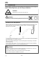
MEK 4S
112101103105107109111102021110025108024042106023061104022041100020040060001
Bruksanvisning
Brugsanvisning
Bruksanvisning
Käyttöohjeet
Instruction manual
Betriebsanweisung
Manuel d’instructions
0455 513 001
020924
Gebruiksaanwijzing
Instrucciones de uso
Istruzioni per l’uso
Manual de instruções
Ïäçãßåò ÷ñÞóåùò
Instrukcja obs³ugi
Valid for serial no. 912--xxx--xxxx
SVENSKA . . . . . . . . . . . . . . . . . . . . . . . . . . . . . . . . . . . . . . . . . . . . . .
3
DANSK . . . . . . . . . . . . . . . . . . . . . . . . . . . . . . . . . . . . . . . . . . . . . . . .
11
NORSK . . . . . . . . . . . . . . . . . . . . . . . . . . . . . . . . . . . . . . . . . . . . . . . . 19
SUOMI . . . . . . . . . . . . . . . . . . . . . . . . . . . . . . . . . . . . . . . . . . . . . . . . 27
ENGLISH . . . . . . . . . . . . . . . . . . . . . . . . . . . . . . . . . . . . . . . . . . . . . . 35
DEUTSCH . . . . . . . . . . . . . . . . . . . . . . . . . . . . . . . . . . . . . . . . . . . . . 43
FRANÇAIS . . . . . . . . . . . . . . . . . . . . . . . . . . . . . . . . . . . . . . . . . . . . . 52
NEDERLANDS . . . . . . . . . . . . . . . . . . . . . . . . . . . . . . . . . . . . . . . . . 61
ESPAÑOL . . . . . . . . . . . . . . . . . . . . . . . . . . . . . . . . . . . . . . . . . . . . . . 70
ITALIANO . . . . . . . . . . . . . . . . . . . . . . . . . . . . . . . . . . . . . . . . . . . . . . 79
PORTUGUÊS . . . . . . . . . . . . . . . . . . . . . . . . . . . . . . . . . . . . . . . . . . 88
ÅËËÇÍÉÊÁ . . . . . . . . . . . . . . . . . . . . . . . . . . . . . . . . . . . . . . . . . . . . .
97
POLSKI . . . . . . . . . . . . . . . . . . . . . . . . . . . . . . . . . . . . . . . . . . . . . . . . . 106
Rätt till ändring av specifikationer utan avisering förbehålles.
Ret til ændring af specifikationer uden varsel forbeholdes.
Rett til å endre spesifikasjoner uten varsel forbeholdes.
Oikeudet muutoksiin pidätetään.
Rights reserved to alter specifications without notice.
Änderungen vorbehalten.
Sous réserve de modifications sans avis préalable.
Recht op wijzigingen zonder voorafgaande mededeling voorbehouden.
Reservado el derecho de cambiar las especificaciones sin previo aviso.
Ci riserviamo il diritto di variare le specifiche senza preavviso.
Reservamo--nos o direito de alterar as especificações sem aviso prévio.
Äéáôçñåßôáé ôï äéêáßùìá ôñïðïðïßçóçò ðñïäéáãñáöþí ×ùñßò ðñïåéäïðïßçóç.
Zastrzegamy sobie prawo do wprowadzenia zmian.
-- 2 --
ENGLISH
1 DIRECTIVE . . . . . . . . . . . . . . . . . . . . . . . . . . . . . . . . . . . . . . . . . . . . . . . . . . . . . . . .
2 SAFETY . . . . . . . . . . . . . . . . . . . . . . . . . . . . . . . . . . . . . . . . . . . . . . . . . . . . . . . . . . .
3 INTRODUCTION . . . . . . . . . . . . . . . . . . . . . . . . . . . . . . . . . . . . . . . . . . . . . . . . . . .
36
36
37
3.1 Explanation of synergic lines . . . . . . . . . . . . . . . . . . . . . . . . . . . . . . . . . . . . . . . . . . . . . . . .
37
4 TECHNICAL DATA . . . . . . . . . . . . . . . . . . . . . . . . . . . . . . . . . . . . . . . . . . . . . . . . .
5 INSTALLATION . . . . . . . . . . . . . . . . . . . . . . . . . . . . . . . . . . . . . . . . . . . . . . . . . . . .
37
37
5.1 Connection . . . . . . . . . . . . . . . . . . . . . . . . . . . . . . . . . . . . . . . . . . . . . . . . . . . . . . . . . . . . . . .
38
6 OPERATION . . . . . . . . . . . . . . . . . . . . . . . . . . . . . . . . . . . . . . . . . . . . . . . . . . . . . . .
39
6.1
6.2
6.3
6.4
Starting to weld . . . . . . . . . . . . . . . . . . . . . . . . . . . . . . . . . . . . . . . . . . . . . . . . . . . . . . . . . . .
Manual mode . . . . . . . . . . . . . . . . . . . . . . . . . . . . . . . . . . . . . . . . . . . . . . . . . . . . . . . . . . . . .
Saving the working setting . . . . . . . . . . . . . . . . . . . . . . . . . . . . . . . . . . . . . . . . . . . . . . . . . .
Program mode . . . . . . . . . . . . . . . . . . . . . . . . . . . . . . . . . . . . . . . . . . . . . . . . . . . . . . . . . . . .
40
41
41
41
7 MAINTENANCE . . . . . . . . . . . . . . . . . . . . . . . . . . . . . . . . . . . . . . . . . . . . . . . . . . . . 42
8 ORDERING SPARE PARTS . . . . . . . . . . . . . . . . . . . . . . . . . . . . . . . . . . . . . . . . . . 42
DIAGRAM . . . . . . . . . . . . . . . . . . . . . . . . . . . . . . . . . . . . . . . . . . . . . . . . . . . . . . . . . . . . 116
SPARE PARTS LIST . . . . . . . . . . . . . . . . . . . . . . . . . . . . . . . . . . . . . . . . . . . . . . . . . . . 117
ACCESSORIES . . . . . . . . . . . . . . . . . . . . . . . . . . . . . . . . . . . . . . . . . . . . . . . . . . . . . . . 124
TOCe
-- 35 --
GB
1
DIRECTIVE
DECLARATION OF CONFORMITY
Esab Welding Equipment AB, S--695 81 Laxå, Sweden, gives its unreserved guarantee that Wire feed unit MEK 4S from serial number 818 complies with standard EN
60974--1, in accordance with the requirements of directive (73/23/EEA) and addendum (93/68/EEA) and standard EN 50199 in accordance with the requirements of
directive (89/336/EEA) and addendum (93/68/EEA).
-------------------------------------------------------------------------------------------------------------------------------------Laxå 98--02--10
Paul Karlsson
Managing Director
Esab Welding Equipment AB
695 81 LAXÅ
SWEDEN
2
Tel: + 46 584 81000
Fax: + 46 584 12336
SAFETY
WARNING
ARC WELDING AND CUTTING CAN BE INJURIOUS TO YOURSELF AND OTHERS. TAKE PRECAUTIONS WHEN WELDING. ASK FOR YOUR EMPLOYER’S SAFETY PRACTICES WHICH SHOULD BE
BASED ON MANUFACTURERS’ HAZARD DATA.
ELECTRIC SHOCK -- Can kill
S
Install and earth the welding unit in accordance with applicable standards.
S
Do not touch live electrical parts or electrodes with bare skin, wet gloves or wet clothing.
S
Insulate yourself from earth and the workpiece.
S
Ensure your working stance is safe.
FUMES AND GASES -- Can be dangerous to health
S
Keep your head out of the fumes.
S
Use ventilation, extraction at the arc, or both, to take fumes and gases away from your breathing zone
and the general area.
ARC RAYS -- Can injure eyes and burn skin.
S
Protect your eyes and body. Use the correct welding screen and filter lens and wear protective
clothing.
S
Protect bystanders with suitable screens or curtains.
FIRE HAZARD
S
Sparks (spatter) can cause fire. Make sure therefore that there are no inflammable materials nearby.
NOISE -- Excessive noise can damage hearing
S
Protect your ears. Use earmuffs or other hearing protection.
S
Warn bystanders of the risk.
MALFUNCTION -- Call for expert assistance in the event of malfunction.
READ AND UNDERSTAND THE INSTRUCTION MANUAL BEFORE INSTALLING OR OPERATING.
PROTECT YOURSELF AND OTHERS!
bm24e
-- 36 --
GB
3
INTRODUCTION
MEK 4S (Synergic)
is an enclosed wire feed unit with four drive rollers. Inside the wire feed unit there is
space for a 300 mm diameter wire reel. The unit also has a built--in swivel mounting
so that the wire feed unit can be conveniently mounted on top of the welding power
source
MEK 4S has many features that welders will find very useful, such as the ability to
save settings for 3 different welding jobs and recall them later, when needed. You
can read about this and much more on the following pages.
Details of ESAB’s accessories for the wire feed units can be found on page
124.
3.1
Explanation of synergic lines
Each combination of wire type, wire diameter and gas mixture requires its own
unigue relationship between the wire feed speed and voltage (arc length) in order to
maintain a stable and effective arc. MEK 4S has 14 different combinations of
pre--programmed “synergic lines”.
Once you have chosen the pre--programmed synergic line that matches your wire
feed speed for your welding task. The voltage (arc length) is automatically adjusted
in accordance with the pre--programmed synergic line yöu have chosen, i.e. you
have one--knob control.
Because different welding tasks and joint preparations require slightly different
voltages (arc lengths) the voltage can naturally be fine--tuned either side of the
pre--programmed value. When this is done the green light on the front panel goes
out. This indicates that the voltage is above or below the pre--programmed value.
If you want to return to the original setting you simply adjust the voltage until the
green light comes on again.
4
TECHNICAL DATA
Dimensions (lxbxh)
606x240x410 mm
Weight
14 kg
Wire feed speed
1,9--25 m/min
Voltage
42 V 50--60 Hz
Power demand
300 VA
Torch connection
EURO
5
INSTALLATION
The installation must be executed by a professional.
WARNING!
This product is intended for industrial use. In a domestic environment this product may cause radio
interference. It is the user’s responsibility to take adequate precautions.
bm24e
-- 37 --
GB
5.1
Connection
1
Nipples for connecting cooling water.
2
Nipple for gas connection.
3
Connector, for connecting control
cable from power supply.
4
Adapter, welding current from
power supply.
5
Switch, crater fill on/off.
6
Digital meter.
7
Encoder, wire feed speed 1.9 -- 25 metres per minute.
8
Encoder, welding voltage.
9
Connector, remote control. Remote control is
activated automatically when connected.
10
Nipples, cooling water to/from welding torch.
11
Bracket for securing strap. The securing
strap must always be used to secure
the wire feed unit to the power source
during transport.
12
Hole for installing connector for PKE
(welding torch with built--in feed motor).
13
Connector for welding torch.
14
Switch trigger latch on/off.
15
Potentiometer, burn--back
time 0--0.5 seconds,
16
Potentiometer, crater fill time 0--5.1 seconds.
17
Jumper, inch start on/off. The jumper is fitted to connector B on the circuit board,
A:
Inch start on, wire feed starts at 1.9 m/min and then rises to set value.
Quick start for restarting with trigger latch on within a second of stopping welding.
Quick start takes place at set wire feed speed.
B:
Normal start, wire feed starts at set value.
18
Brake hub. Hub is pre--adjusted prior to delivery.
19
Switch for program selection.
20
Pushbutton for storing settings.
21
Indicator lamp for stored settings.
22
Switch for function selection.
23
Pushbutton for pre--setting wire feed speed and reference voltage.
24
Indicator lamp for working point.
25
Switch for selecting synergic lines 1A--8A or 1B--8B.
bm24e
-- 38 --
GB
6
OPERATION
General safety regulations for the handling of the equipment can be found on
page 36. Read through before you start using the equipment!
WARNING!
Rotating parts can cause injury, take great care.
WARNING!
To prevent the reel sliding off the hub: Lock the reel in place by turning
the red knob as shown on the warning label attached next to the hub.
Setting the wire feed pressure
Start by making sure that the wire moves smoothly through the wire guide. Then
set the pressure of the wire feeder’s pressure rollers. It is important that the
pressure is not too great.
Fig 1
Fig 2
To check that the feed pressure is set correctly, you can feed out the wire against
an isolated object, e.g. a piece of wood.
When you hold the pistol approx. 5 mm from the piece of wood (fig. 1) the feed
rollers should slip.
If you hold the pistol approx. 50 mm from the piece of wood, the wire should be
feed out and bend (fig. 2). ja sen on taivuttava (kuva 2).
WARNING!
There is a risk of tipping if the wire feed cabinet is fitted with a counterbalance arm. Secure the
equipment, especially if used on an uneven or sloping surface.
Limit the angle of rotation of the wire feed cabinet using the straps supplied.
When moving the equipment, do NOT pull on the torch.
bm24e
-- 39 --
GB
6.1
Starting to weld
By moving the plug (17) to the upper or lower position you can switch between two
different start modes.
Normal start
with the plug (17) in the lower position the wire feed speed at the start of welding is
the same as the preset wire feed speed during welding.
Inch start
with the plug (17) in the upper position the wire feed speed at the start of welding is
reduced (1.9 m/min) and then rises to the preset wire feed speed when the arc is
established.
6.1.1
Synergic mode
Set the toggle switch on the circuit board (25) to position A and set the selector
switch on the front panel (22) to the synergic line that matches the wire type, wire
diameter and gas you intend to use. There are 8 synergic lines to choose from.
(see table page 44).
When the “Pre--set” button (23) is pushed in, the wire feed speed and voltage are
shown on the display.
The green lamp (24) above the voltage control will light up when the voltage falls on
the synergic line. You can use the voltage control knob (8) to adjust the voltage
around the working point.
The actual voltage and current are shown on the display during welding.
A further 6 synergic lines can be accessed by setting the toggle switch on the circuit
board to position B (see table page 44).
Syn.line
Matr./Size, mm
Gas / %
Syn.line
Matr./Size, mm
Gas / %
A1
Fe /1,0
Ar 80% CO2 20%
B1
MCW / 1,2
Ar 80% CO2 20%
A2
Fe /1,2
Ar 80% CO2 20%
B2
MCW / 1,6
Ar 80% CO2 20%
A3
Ss /1,0
Ar 98% CO2 2%
B3
RFCW / 1,2
Ar 80% CO2 20%
A4
Ss /1,2
Ar 98% CO2 2%
B4
RFCW / 1,6
Ar 80% CO2 20%
A5
Al. Mg /1,2
Ar 100%
B5
BFCW / 1,2
Ar 80% CO2 20%
A6
Al. Mg /1,6
Ar 100%
B6
BFCW / 1,6
Ar 80% CO2 20%
A7
Al. Si /1,2
Ar 100%
A8
Al. Si /1,6
Ar 100%
PAH1
B7
B8
6.1.2
Creating your own synergic lines
If the pre--programmed synergic lines do not suit your combination of wire, wire
diameter and gas maxture, you can use the PAH1 controller, part no. 0455 525 880,
to create 2 synergic lines of your own and save them in the MEK4S menory.
See the user manual for the PAH1 controller.
Contact your nearest ESAB dealer for more information about this feature.
bm24e
-- 40 --
GB
6.2
Manual mode
Adjusting voltage and wire feed speed.
Set the selector switch on the front panel (22) to manual.
Hold in the “pre--set” button (23) while you set the desired voltage and wire feed
speed on the display. The actual voltage and current are shown on the display during
welding.
NOTE! Pulse welding is not possible in manual mode.
6.3
Saving the working setting
Set the program selector switch (19) to one of the three settings 1,2 or 3. Hold in the
“pre--set” button (23) while you set the desired voltage and wire feed speed on the
display. To save the welding parameters you have selected, press the save button
(20) until the green lamp (21) lights up. You can save three different working settings
using the program selector switch.
6.4
Program mode
To use one of the 3 stored working settings, switch the function selector switch (22)
on the front panel to mode “P” and the program selector switch (19) to mode 1,2 or 3
to recall the chosen data and begin welding.
These weld data settings can also be recalled using the program selector switch on
the welding torch.
It is not possible to adjust the voltage or the wire feed speed around the chosen
working setting.
bm24e
-- 41 --
GB
7
MAINTENANCE
Note:
All warranty undertakings given by the supplier cease to apply if the customer
attempts to rectify any faults on the machine during the warranty period.
Regular maintenance is important for safe and reliable operation.
S
Regularly blow the wire liner clean and clean the gas nozzle.
S
The wear components of the wire feed mechanism should be replaced at regular
intervals in order to ensure reliable wire feeding.
Note that using excessive pressure on the wire feed rollers can cause excessive
wear to the pressure roller, feed roller and wire liner.
The brake hub
The hub is adjusted when delivered, if
readjustment is required, follow the instructions
below. Adjust the brake hub so that wire is slightly
slack when wire feed stops.
S
Adjusting the braking torque:
S
Turn the red handle to the locked position.
S
Insert a screwdriver into the springs in the hub.
Turn the springs clockwise to reduce the braking torque
Turn the springs anticlockwise to increase the braking torque. NB: Turn both
springs through the same amount.
8
ORDERING SPARE PARTS
Spare parts are ordered through your nearest ESAB representative, see back cover.
When ordering spare parts, please state machine type and number as well as designation and spare part number as shown in the spare parts list.
This will simplify dispatch and ensure you get the right part.
bm24e
-- 42 --