1
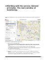
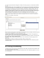
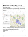
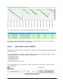
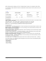
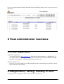
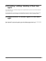
ORF Monitor user manual
Version 2.0
CONTENTS:
1
General provisions
2
2
Users of the service
3
3
Service logon
3
4
Working with the service. General principles. The
main window of monitoring.
4
5
5
Fleet manager functions
5.1
5.2
5.3
5.4
5.5
5.6
6
Single unit monitoring .................................................................................... 5
Creating / editing / deleting groups of units ............................................ 5
Group monitoring ............................................................................................. 6
Creating/editing/deleting geo-zones .......................................................... 7
Geo-zone monitoring....................................................................................... 8
Analytical report viewing................................................................................ 8
5.6.1 Fuel report (
)............................................................................. 8
5.6.2 Movement report (
)............................................................... 10
5.6.3 Units group report (
)............................................................. 12
5.6.4 Geo-zone visiting report ................................................................ 12
Fleet administrator functins
6.1
6.2
6.3
6.4
134
Fleet registration .............................................................................................. 13
Registration/ editing/ deleting of units
!
.
Creating/ editing/ deleting of fleet managers
Appointment of access rights to the manager
User_manual-ORF version 2.0.doc
!
.
!
.
.1
15
1 General provisions
Read carefully the user manual before working with ORF Monitor service. The document contains the necessary information about using the service in Web-browser.
ORF Monitor - real-time vehicle monitoring service.
ORF Monitor is intended for on-board vehicle reports reception through the Internet,
processing and displaying operational data: the current position and operational parameters
of the vehicle or group of vehicles. There is also a function of analytical reports preparation.
The vehicle must be equipped with a terminal supported by the service. The terminal is designed for measuring signals of standard and additional sensors, receiving the coordinate
data from navigation satellites, obtaining data from CAN bus. The terminal makes up reports
and sends them to access points. ORF Monitor receives vehicle reports from GPRS and SMS
access points.
How it works is shown in the figure:
User_manual-ORF version 2.0.doc
.2
15
2 Users of the service
Organizational unit in the ORF Monitor service is a vehicle fleet. Every fleet contains units
(vehicles). Only one user with the extended rights can be created for each vehicle fleet. It is
fleet administrator. Also there can be created an unlimited number of users with the usual
set of rights - fleet managers.
Service functional provided for fleet manager:
• Single vehicle monitoring;
• Creating / editing / deleting vehicle groups;
• Vehicle group monitoring;
• Creating / editing / deleting geo-zones;
• Geo-zones monitoring;
• Analytic reports viewing: on one vehicle and a group of vehicles.
In addition, the fleet administrator may:
• Register fleet;
• Create / edit / delete vehicles;
• Create / edit / delete fleet managers;
• Set the access rights of managers to vehicles.
3 Service logon
To enter the service ORF Monitor, you must have a modern Web-browser. The list of supported browsers:
• Internet Explorer 6.0 + (Windows)
• Firefox 0.8 + (Windows, Linux)
Enter the URL of the service ORF Monitor (http://www.orf-monitor.com) in the address bar
of your browser to open the HTML login page of ORF Monitor. Enter your username and
password and click “Login” if you are already a registered user of the service. Contact the
administrator of your fleet to create your user profile, if you have not registered yet.
If you forgot your password, click on “Forget password?” and follow the instructions.
User_manual-ORF version 2.0.doc
.3
15
4 Working with the service. General
principles. The main window of
monitoring.
Entering the ORF Monitor service, the main window of monitoring site opens. It looks as follows:
The window is divided into three main areas:
1) Menu area is in the upper part.
In the menu area you can select the preferred language. English, German and Russian languages are currently supported. Also, there is login name, server time and
links:
• “Documentation” is a reference to the latest version of this document.
• “Geo-zones” is a link to the “Geo-zones” window. For more information see the section “Working with geo-zones”.
• “Logout” is a link to logout the user from the service.
2) The area of information and management is on the left. It contains the following
panes:
• Monitoring units - the pane displays a list of vehicles, provides controls for groups
management, displays the data from the last report of the vehicle.
User_manual-ORF version 2.0.doc
.4
15
• Account - the pane is for viewing the fleet status - the balance, the number of users and vehicles, as well as performs some commands that are available only to fleet
administrator.
• Geo-zones list – the pane is for control displaying of client’s geo-zones on the map.
• Monitoring options - the pane is for control displaying of the units on the map.
3) Map is on the right side.
“Google Maps” system is used to display the maps. There are 3 forms of maps: ordinary map, satellite view and mixed (click “Map”, “Satellite” and “Hybrid” respectively). Also there is the ability to display custom maps (“ADF GIS3” button). The system
allows you to change the map scale, as well as map preview. The navigation is performed by the mouse.
5 Fleet manager functions
5.1 Single unit monitoring
Unit is a vehicle equipped with a terminal, registering and transferring the parameters of
vehicle motion and operation.
The vehicles of your fleet are represented in the information panel “Units”. The list displays
the name of the unit and the associated image (only for browser “Firefox”). When you select
the unit in the list, its image is automatically displayed in the center of the map window.
Units represented by the icon in the form of red circle on the map by default. The image of
the particular icon represents unit on the map, if assigned.
Selecting the unit in the list, you will get supplementary information in the “State” pane. Location address and values of operational parameters from the latest vehicle report becomes
automatically available.
The following options must be selected (switched on) in the “Monitoring options” to monitor
a single unit:
• “Center map on new messages”
• “Show on map only selected object”
5.2 Groups of units creating / editing / deleting
Group of units – some vehicles united on any distinctive features appear in the “Units” list.
Any user can create / modify / delete a group of units.
There are predefined groups of units in the service: "All units", "Moving units", "Staying
units”. The names of these groups say themselves about the ground on which they are unit-
User_manual-ORF version 2.0.doc
.5
15
ed. These groups cannot be changed or deleted. All other groups are created and modified
by user.
All the available units may be included into any user group. Any unit may be included into
more than one group or not included to any. Any characteristic of the vehicle may be used
as a feature for inclusion the unit into the group, in particular: vehicle’s brand, route, etc.
The grouping is an appropriate solution for fast and convenient navigation between units
especially if the number of vehicles in the fleet is more than a few hundreds. All the current
settings (selected group and the unit) are saved for the user when he leaves the service.
These settings will be restored for the user on subsequent entry to the service.
The list of groups is represented in the form of drop-down list on the information panel
“Units”. Click “Create” button at the bottom and right of the list to create a new group of
units.
The form for creating a new group:
Enter the name of the group in the “Name” field and add all the necessary units from the list
“All” to the list “Assigned” to create the group of units.
To add a single vehicle, click on it in the “All” list, and then click “Add”. This operation removes it from the “All” list and adds it to the “Assigned” list.
Click “Create” to save the new group after adding all the necessary vehicles. The Group will
be created. Click “Close” button to finish.
Refresh the main window (the Refresh button in your browser) to see new group in the
group list.
Group editing is similar to creating, the button “Edit” is used for that.
To delete a group, select the group and click the “Delete” button on the “Monitoring Units”
information pane.
5.3 Group monitoring
To display all the units from the selected group on the map, you should use the button “See
all” on the “Monitoring units” pane.
The following options must be deselected (switched off) in the “Monitoring options” to monitor a units group:
User_manual-ORF version 2.0.doc
.6
15
• “Center map on new messages”;
• “Show on map only selected object”.
5.4 Geo-zones creating/editing/deleting
Geo-zone is a user-defined area on an electronic map. In the ORF Monitor geo-zones are
given in the form of a polygon.
Geo-zone toolkit allows the fleet manager to perform the following functions:
1. Monitoring of drivers assignments in serving the specified objects; including the number
of visits, the time of arrival and machine idle time at the served object.
2. Automatic control of vehicle position within a given geo-zone. An automatic alarm sending
to the certain e-mail addresses or phone numbers can be appointed to the event of leaving
the geo-zone.
3. Quick jumping to a pre stored geo-zones for their control in monitoring mode.
Geo-zones creating, editing and deleting is performed in the “Geo-zones” window (use "Geozones" link in the main monitoring window). The window looks as follows:
There is a link to return to the main monitoring window in the top of the screen. There are
three panels on the left side:
• “Geo-zone creation” contains the necessary fields and buttons to create a new geo-zone.
The new geo-zone creation mode is enabled by pressing “Create”.
• “Geo-zones list” - contains the list of all geo-zones of the user. Geo-zones can be viewed,
edited and deleted.
• “Help” - online help window, which helps the user to perform any operations with geozones.
User_manual-ORF version 2.0.doc
.7
15
5.5 Geo-zones monitoring
Geo-zones monitoring can be used by the fleet manager when tracking should be carried out
not for the vehicle but for a certain territory. There is a pane “Geo-zones list” in the main
window; it should be used for moving quickly between Geo-zones for monitoring. The pane
is designed to control the geo-zones displaying on the map, as well as the rapid transition to
the selected geo-zone.
The option “Center map on new messages” must be deselected (switched off) in the “Monitoring
options”
to
monitor
selected
geo-zone
in
the
geo-zones
list.
The option “Show on map only selected object” must be deselected (switched off) in the
“Monitoring options” to monitor the vehicles entering and leaving the geo-zone.
5.6 Analytical reports viewing
The ability to perform the analytical reports has been implemented to process the data received from the vehicles. The report allows to systematize the data from the vehicle over a
period of time, to provide the data in tabular and in graphical form, to show the values of
parameters and counters of the vehicle.
Choose the report from the list in the information pane “Reports” and press “Show” to view
it.
5.6.1
Fuel report (CKPT)
Important! The data should be obtained from a CKPT terminal to create the report contained
the correct data.
The report allows you to display complete data on the vehicle fuel consumption, refilling and
discharging the tank. The report uses the data from the fuel level sensor in the tank (DUT)
and the fuel flow meter (DPT) in the fuel line or fuel consumption data from the CAN bus.
The report will be incomplete in the case of data absence from one of the sensors. The values for the missing parameters are displayed in the report in the form «--». The report consists of five blocks:
• Configuration pane;
• The “Statistics” pane;
• The “Map” pane;
• The “Chart” pane;
• The “Fuel events” pane.
The configuration pane is designed to change the settings of the report: vehicle and time
interval selection.
After selecting these settings, click the “Update Report” button for changes to take effect.
User_manual-ORF version 2.0.doc
.8
15
The “Statistics” pane shows the values of parameters and counters of the vehicle for the selected period.
The counters:
“Total distance” - the counter figure, passed by the terminal and formed on the basis of GPS
data or speed sensor data.
“Movement time” - the counter figure, passed and formed by the terminal.
“Fuel consumed” - the counter figure, passed by the terminal and formed on the basis of
DUT, DPT or CAN bus data.
“Number | Fueling amount” - the number of events “Filling” fixed by the terminal, and the
total amount of fuel filled into the tank. These are formed on the basis of DUT data.
“Number | Draining amount” - the number of events "Draining" fixed by the terminal, and
the total amount of fuel drained from the tank. These are formed on the basis of DUT data.
The parameters:
“Fuel in the tank start” - the fuel value in the tank at the beginning of the period, according
to the DUT data.
“Fuel in the tank finish” - the fuel value in the tank at the end of the period, according to the
DUT data.
“Hourly fuel consumption” - the value of average hourly fuel consumption that is passed by
the terminal, and formed on the basis of DUT, DPT or CAN bus data.
The "Map" pane is used to display a map with drawing the vehicle track on it, as well as
icons of fuel events.
The "Chart" pane is to display the graphic of user-selectable parameters:
• Fuel volume in the tank;
• Fuel volume in the tank (CAN);
• Fuel tank hourly consumption (DUT);
• Fuel flow hourly consumption (DPT) ;
• Fuel CAN hourly consumption (CAN);
• Trip fuel consumption (DPT);
• Trip (GPS) fuel consumption (DPT);
• Trip fuel consumption (CAN);
• Trip (GPS) fuel consumption (CAN).
User_manual-ORF version 2.0.doc
.9
15
The “Fuel events” pane is used for displaying tabular data on recorded events.
Clicking the mouse on the table cell "Location" in the map window you can see a marker
showing the place of fuel filling or discharging.
5.6.2
Movement report (
)
Important! The data should be obtained from a CKPT terminal to create the report contained
the correct data.
The report allows you to display complete data on the vehicle movement, parking, engine
working parameters. The report consists of five blocks:
Configuration pane;
The “Statistic” pane;
The “Map” pane;
The “Chart” pane;
The “Movement events” pane.
The configuration pane is designed to change the settings of the report: vehicle and time
interval selection.
User_manual-ORF version 2.0.doc
. 10
15
After selecting these settings, click the “Update Report” button for changes to take effect.
The “Statistics” pane shows the values of parameters and counters of the vehicle for the selected period.
The counters:
“Total distance” - the counter figure, passed by the terminal and formed on the basis of GPS
data or speed sensor data.
“Movement time” - the counter figure, passed and formed by the terminal.
Engine run time - the counter figure, passed and formed by the terminal.
Motor-hour - the counter figure, passed and formed by the terminal.
The parameters:
Average speed – calculated parameter’s value according to the terminal data, formed on the
basis of speed sensor or GPS data.
Maximal speed - calculated parameter’s value according to the terminal data, formed on the
basis of speed sensor or GPS data.
Average engine speed - calculated parameter’s value according to the terminal data, formed
on the basis of sensor’s data.
Average engine temperature - calculated parameter’s value according to the terminal data,
formed on the basis of temperature sensor of refrigerating fluid.
Average engine oil pressure - calculated parameter’s value according to the terminal data,
formed on the basis of pressure sensor.
Average axis weight - calculated parameter’s value according to the terminal data, formed
on the basis of axis weight sensor.
The “Map” pane is for displaying movement track of the vehicle and event icons – parking.
The “Chart” pane is for displaying value changes over the time of one of the following parameters selected by the client:
Unit speed;
Engine speed;
Axis weight;
Board voltage.
User_manual-ORF version 2.0.doc
. 11
15
The “Movement event” pane is for table view displaying of full data with the fixed events of
the vehicle – movement and parking intervals.
5.6.3
Units group report (
)
The report represents aggregated data of the main exploitation parameters of the vehicles
within the selected time interval.
5.6.4
Geo-zone visiting report
The report is built on the basis of notifications created by the server according to the event
data of entering and exiting selected geo-zones by particular vehicle. Switching on the notifications of geo-zone visiting is performed in the “Notifications” tab of the vehicle parame-
User_manual-ORF version 2.0.doc
. 12
15
ters. The report window contains the table with the following data: time in, time out, time in
geo-zone.
6 Fleet administrator functions
6.1 Fleet registration
Step1. Fleet registration
To register fleet go to http://orfservice.ru. Menu point «
» or “Registration”. To
the e-mail indicated in the registration form the letter with the access point addresses GPRS
and SMS, login and pass of the fleet administrator will be sent.
Step 2. Terminal set up
Insert the access point addresses GPRS and SMS into the board terminals according to Installation manuals of the terminal.
6.2 Registration/ editing/ deleting of units
To create a new unit press “Create” button below the “Units” list.
User_manual-ORF version 2.0.doc
. 13
15
To create a new Unit should be filled the following fields:
Controller model – selecting the terminal model from the list of installed one on the
vehicle;
Unit name – vehicle’s name, displaying on the monitoring website and in the reports.
Recommended as the unit name selecting the model and state registration number of
the vehicle;
Unique ID – unique sequence of characters used for information identification from
present vehicle (usually serial number of the terminal installed on the vehicle);
Phone number SIM – phone number of the SIM-card installed into the terminal.
The remaining fields are not necessary to fill.
To make changes into the parameters of the unit select necessary vehicle from the list and
press “Properties” button.
Together with the “General” tab when registering the vehicle this form contains two other
tabs:
The “Notifications” tab – is for creating and editing the server “Notifications” according to
selected vehicle when the vehicle is entering and exiting geo-zone. For any type of events
can be assigned generation of notifications to specified e-mails or mobile phones.
The “Sensors” tab – allows the user to create a list of sensors connected to onboard terminal.
Changing of the unit parameters is possible only if the user has appropriate rights (editing).
If the User does not have such rights so editing and deleting of the vehicle parameters are
forbidden. (corresponding buttons are blocked).
User_manual-ORF version 2.0.doc
. 14
15
6.3 Creating/ editing/ deleting of fleet managers
The registration of a new fleet manager can be performed only at the level of Fleet Administrator access rights.
The management is curried out in the information area of the “Account” tab. Creating/ editing/ deleting of the fleet managers is performed by clicking on the link “Manage users”.
6.4 Appointment of access rights to the manager
Fleet administrator has access right to the link “Manage unites access” in the information
pane “Account” – allows and restricts rights of the fleet managers to the units.
User_manual-ORF version 2.0.doc
. 15
15