1
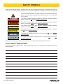
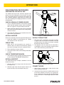
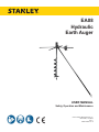
EA08
Hydraulic
Earth Auger
USER MANUAL
Safety, Operation and Maintenance
© 2014 Stanley Black & Decker, Inc.
New Britain, CT 06053
U.S.A.
43668 2/2015 Ver. 6
DECLARATION OF CONFORMITY
DECLARATION OF CONFORMITY
ÜBEREINSTIMMUNGS-ERKLARUNG
DECLARATION DE CONFORMITE CEE
DECLARACION DE CONFORMIDAD
DICHIARAZIONE DI CONFORMITA
Hydraulic Tools
______________________________________________________________________
I, the undersigned:
Ich, der Unterzeichnende:
Je soussigné:
El abajo firmante:
lo sottoscritto:
Weisbeck, Andy
Surname and First names/Familiennname und Vornamen/Nom et prénom/Nombre y apellido/Cognome e nome
hereby declare that the equipment specified hereunder:
bestätige hiermit, daß erklaren Produkt genannten Werk oder Gerät:
déclare que l’équipement visé ci-dessous:
Por la presente declaro que el equipo se especifica a continuación:
Dichiaro che le apparecchiature specificate di seguito:
1.
Category:
Kategorie:
Catégorie:
Categoria:
Categoria:
Earth Auger, Hydraulic
2.
Make/Marke/Marque/Marca/Marca
Stanley
3.
Type/Typ/Type/Tipo/Tipo:
EA08102A
4.
Serial number of equipment:
Seriennummer des Geräts:
Numéro de série de l’équipement:
Numero de serie del equipo:
Matricola dell´attrezzatura:
All
Has been manufactured in conformity with
Wurde hergestellt in Übereinstimmung mit
Est fabriqué conformément
Ha sido fabricado de acuerdo con
E’ stata costruita in conformitá con
Directive/Standards
Richtlinie/Standards
Directives/Normes
Directriz/Los Normas
Direttiva/Norme
No.
Nr
Numéro
No
n.
Approved body
Prüfung durch
Organisme agréé
Aprobado
Collaudato
EN ISO
EN ISO
Machinery Directive
EN ISO
20643:2005
3744:2010
2006/42/EC:2006
12100:2010
Self
Self
Self
Self
5.
Special Provisions:
None
Spezielle Bestimmungen:
Dispositions particulières:
Provisiones especiales:
Disposizioni speciali:
6.
Representative in the Union: Patrick Vervier, Stanley Dubuis 17-19, rue Jules Berthonneau-BP 3406 41034 Blois Cedex, France.
Vertreter in der Union/Représentant dans l’union/Representante en la Union/Rappresentante presso l’Unione
Done at/Ort/Fait à/Dado en/Fatto a Stanley Hydraulic Tools, Milwaukie, Oregon USA
Signature/Unterschrift/Signature/Firma/Firma
Position/Position/Fonction/Cargo/Posizione
2 ► EA08 User Manual
Director of Product Development
Date/Datum/le/Fecha/Data
1-10-11
TABLE OF CONTENTS
DECLARATION OF CONFORMITY...........................................................................................................................2
SAFETY SYMBOLS...................................................................................................................................................4
SAFETY PRECAUTIONS...........................................................................................................................................5
TOOL STICKERS & TAGS.........................................................................................................................................6
HOSE TYPES.............................................................................................................................................................7
HOSE RECOMMENDATIONS...................................................................................................................................8
FIGURE 1. TYPICAL HOSE CONNECTIONS........................................................................................................8
HTMA REQUIREMENTS............................................................................................................................................9
OPERATION.............................................................................................................................................................10
FIGURE 2. INSTALLING THE AUGER.................................................................................................................10
FIGURE 3. INSTALLING TORQUE TUBE............................................................................................................10
TROUBLESHOOTING.............................................................................................................................................12
SPECIFICATIONS....................................................................................................................................................13
ACCESSORIES.......................................................................................................................................................13
EA08 PARTS ILLUSTRATION.................................................................................................................................14
EA08 PARTS LIST...................................................................................................................................................15
IMPORTANT
To fill out a Product Warranty Validation form, and for information on your warranty,
visit Stanleyhydraulics.com and select the Company tab, Warranty.
(NOTE: The warranty Validation record must be submitted to validate the warranty).
SERVICING: This manual contains safety, operation, and routine maintenance instructions. Stanley Hydraulic
Tools recommends that servicing of hydraulic tools, other than routine maintenance, must be performed by an authorized and certified dealer. Please read the following warning.
WARNING
SERIOUS INJURY OR DEATH COULD RESULT FROM THE IMPROPER REPAIR OR
SERVICE OF THIS TOOL.
REPAIRS AND / OR SERVICE TO THIS TOOL MUST ONLY BE DONE BY AN
AUTHORIZED AND CERTIFIED DEALER.
For the nearest authorized and certified dealer, call Stanley Hydraulic Tools at the number listed on the back of this
manual and ask for a Customer Service Representative.
EA08 User Manual ◄ 3
SAFETY SYMBOLS
Safety symbols and signal words, as shown below, are used to emphasize all operator, maintenance and repair actions which, if not strictly followed, could result in a life-threatening situation, bodily injury or damage to equipment.
This is the safety alert symbol. It is used to alert you to potential personal injury
hazards. Obey all safety messages that follow this symbol to avoid possible
injury or death.
DANGER
This safety alert and signal word indicate an imminently hazardous situation
which, if not avoided, will result in death or serious injury.
WARNING
This safety alert and signal word indicate a potentially hazardous situation
which, if not avoided, could result in death or serious injury.
CAUTION
This safety alert and signal word indicate a potentially hazardous situation
which, if not avoided, could result in death or serious injury.
CAUTION
This signal word indicates a potentially hazardous situation which, if not avoided, may result in property damage.
NOTICE
This signal word indicates a situation which, if not avoided, will result in damage
to the equipment.
IMPORTANT
This signal word indicates a situation which, if not avoided, may result in damage to the equipment.
Always observe safety symbols. They are included for your safety and for the protection of the tool.
LOCAL SAFETY REGULATIONS
Enter any local safety regulations here. Keep these instructions in an area accessible to the operator and maintenance personnel.
4 ► EA08 User Manual
SAFETY PRECAUTIONS
Tool operators and maintenance personnel must always
comply with the safety precautions given in this manual
and on the stickers and tags attached to the tool and
hose.
earth auger. Loose fitting clothing can get entangled
with the earth auger and cause serious injury.
•
Always operate the earth auger at full throttle. Operating the earth auger with the trigger slightly
depressed raises the hydraulic pressure which increases torque output. This type of operation can
result in unexpected “kickback”.
Supervising personnel should develop additional precautions relating to the specific work area and local
safety regulations. If so, place the added precautions in
the space provided in this manual.
•
Do not remove the earth auger from a hole until it
has completely stopped turning.
•
The EA08 Hydraulic Earth Auger will provide safe and
dependable service if operated in accordance with the
instructions given in this manual. Read and understand
this manual and any stickers and tags attached to the
tool and hoses before operation. Failure to do so could
result in personal injury or equipment damage.
Supply hoses must have a minimum working pressure rating of 2500 psi/175 bar.
•
Be sure all hose connections are tight.
•
The hydraulic circuit control valve must be in the
OFF position when coupling or uncoupling the tool.
Wipe all couplers clean before connecting. Failure
to do so may result in damage to the quick couplers
and cause overheating of the hydraulic system. Use
only lint-free cloths.
•
Do not operate the tool at oil temperatures above
140 °F/60 °C. Operation at higher oil temperatures
can cause operator discomfort and may damage the
tool.
•
Do not operate a damaged, improperly adjusted, or
incompletely assembled tool.
•
To avoid personal injury or equipment damage, all
tool repair, maintenance and service must only be
performed by authorized and properly trained personnel.
These safety precautions are given for your safety. Review them carefully before operating the tool and before
performing general maintenance or repairs.
•
Operator must start in a work area without bystanders. The operator must be familiar with all prohibited
work areas such as excessive slopes and dangerous terrain conditions.
•
Establish a training program for all operators to ensure safe operation.
•
Do not operate the tool unless thoroughly trained or
under the supervision of an instructor.
•
•
Always wear safety equipment such as goggles,
head protection, and safety shoes at all times when
operating the tool.
Do not exceed the rated limits of the tool or use the
tool for applications beyond its design capacity.
•
Always keep critical tool markings, such as labels
and warning stickers legible.
•
Do not inspect or clean the tool while the hydraulic
power source is connected. Accidental engagement
of the tool can cause serious injury.
•
Always replace parts with replacement parts recommended by Stanley Hydraulic Tools.
•
Check fastener tightness often and before each use
daily.
•
Do not operate the earth auger without first installing
the torque tube.
•
Do not install or remove an auger while the hydraulic
power source is connected. Accidental engagement
of the tool can cause serious injury.
•
Never operate the earth auger if you cannot be sure
that underground utilities are not present. Underground electrical utilities present an electrocution
hazard. Underground gas utilities present an explosion hazard. Other underground utilities may present other hazards.
•
Do not wear loose fitting clothing when operating the
EA08 User Manual ◄ 5
TOOL STICKERS & TAGS
23139
NAME TAG
11206
CIRCUIT C STICKER
11207
CIRCUIT D DECAL
WARNING
CALL BEFORE
YOU DIG
28323
CE DECAL
39423
COMPOSITE DECAL
66409
SOUND POWER DECAL
39424
WARNING DECAL
NOTE:
THE INFORMATION LISTED
ON THE STICKERS SHOWN,
MUST BE LEGIBLE AT ALL
TIMES.
REPLACE DECALS IF
THEY BECOME WORN OR
DAMAGED. REPLACEMENTS
ARE AVAILABLE FROM
YOUR LOCAL STANLEY
DISTRIBUTOR.
The safety tag (P/N 15875) at right is
attached to the tool when shipped from
the factory. Read and understand the
safety instructions listed on this tag before
removal. We suggest you retain this tag and
attach it to the tool when not in use.
D A N G E R
1.
FAILURE TO USE HYDRAULIC HOSE LABELED AND CERTIFIED AS NON-CONDUCTIVE WHEN USING HYDRAULIC
TOOLS ON OR NEAR ELECTRICAL LINES MAY RESULT IN
DEATH OR SERIOUS INJURY.
BEFORE USING HOSE LABELED AND CERTIFIED AS NONCONDUCTIVE ON OR NEAR ELECTRIC LINES BE SURE THE
HOSE IS MAINTAINED AS NON-CONDUCTIVE. THE HOSE
SHOULD BE REGULARLY TESTED FOR ELECTRIC CURRENT LEAKAGE IN ACCORDANCE WITH YOUR SAFETY
DEPARTMENT INSTRUCTIONS.
2.
A HYDRAULIC LEAK OR BURST MAY CAUSE OIL INJECTION INTO THE BODY OR CAUSE OTHER SEVERE
PERSONAL INJURY.
A.
DO NOT EXCEED SPECIFIED FLOW AND PRESSURE
FOR THIS TOOL. EXCESS FLOW OR PRESSURE MAY
CAUSE A LEAK OR BURST.
B.
DO NOT EXCEED RATED WORKING PRESSURE OF
HYDRAULIC HOSE USED WITH THIS TOOL. EXCESS
PRESSURE MAY CAUSE A LEAK OR BURST.
C. CHECK TOOL HOSE COUPLERS AND CONNECTORS
DAILY FOR LEAKS. DO NOT FEEL FOR LEAKS WITH
YOUR HANDS. CONTACT WITH A LEAK MAY RESULT
IN SEVERE PERSONAL INJURY.
D A N G E R
D. DO NOT LIFT OR CARRY TOOL BY THE HOSES. DO
NOT ABUSE HOSE. DO NOT USE KINKED, TORN OR
DAMAGED HOSE.
3.
MAKE SURE HYDRAULIC HOSES ARE PROPERLY CONNECTED TO THE TOOL BEFORE PRESSURING SYSTEM.
SYSTEM PRESSURE HOSE MUST ALWAYS BE CONNECTED TO TOOL “IN” PORT. SYSTEM RETURN HOSE
MUST ALWAYS BE CONNECTED TO TOOL “OUT” PORT.
REVERSING CONNECTIONS MAY CAUSE REVERSE
TOOL OPERATION WHICH CAN RESULT IN SEVERE
PERSONAL INJURY.
4.
DO NOT CONNECT OPEN-CENTER TOOLS TO CLOSEDCENTER HYDRAULIC SYSTEMS. THIS MAY RESULT IN
LOSS OF OTHER HYDRAULIC FUNCTIONS POWERED BY
THE SAME SYSTEM AND/OR SEVERE PERSONAL INJURY.
5.
BYSTANDERS MAY BE INJURED IN YOUR WORK AREA.
KEEP BYSTANDERS CLEAR OF YOUR WORK AREA.
6.
WEAR HEARING, EYE, FOOT, HAND AND HEAD PROTECTION.
7.
TO AVOID PERSONAL INJURY OR EQUIPMENT DAMAGE,
ALL TOOL REPAIR MAINTENANCE AND SERVICE MUST
ONLY BE PERFORMED BY AUTHORIZED AND PROPERLY
TRAINED PERSONNEL.
I M P O R T A N T
I M P O R T A N T
READ OPERATION MANUAL AND
SAFETY INSTRUCTIONS FOR THIS
TOOL BEFORE USING IT.
READ OPERATION MANUAL AND
SAFETY INSTRUCTIONS FOR THIS
TOOL BEFORE USING IT.
USE ONLY PARTS AND REPAIR
PROCEDURES APPROVED BY
STANLEY AND DESCRIBED IN THE
OPERATION MANUAL.
USE ONLY PARTS AND REPAIR
PROCEDURES APPROVED BY
STANLEY AND DESCRIBED IN THE
OPERATION MANUAL.
TAG TO BE REMOVED ONLY BY
TOOL OPERATOR.
TAG TO BE REMOVED ONLY BY
TOOL OPERATOR.
SEE OTHER SIDE
SEE OTHER SIDE
SAFETY TAG P/N 15875 (Shown smaller then actual size)
6 ► EA08 User Manual
HOSE TYPES
The rated working pressure of the hydraulic hose must be equal to or higher than the relief valve setting on the hydraulic system. There are three types of hydraulic hose that meet this requirement and are authorized for use with
Stanley Hydraulic Tools. They are:
Certified non-conductive — constructed of thermoplastic or synthetic rubber inner tube, synthetic fiber braid
reinforcement, and weather resistant thermoplastic or synthetic rubber cover. Hose labeled certified nonconductive is the only hose authorized for use near electrical conductors.
Wire-braided (conductive) — constructed of synthetic rubber inner tube, single or double wire braid reinforcement, and weather resistant synthetic rubber cover. This hose is conductive and must never be used near
electrical conductors.
Fabric-braided (not certified or labeled non-conductive) — constructed of thermoplastic or synthetic rubber inner tube, synthetic fiber braid reinforcement, and weather resistant thermoplastic or synthetic rubber cover. This
hose is not certified non-conductive and must never be used near electrical conductors.
HOSE SAFETY TAGS
To help ensure your safety, the following DANGER tags are attached to all hose purchased from Stanley Hydraulic
Tools. DO NOT REMOVE THESE TAGS.
If the information on a tag is illegible because of wear or damage, replace the tag immediately. A new tag may be
obtained from your Stanley Distributor.
D A N G E R
D A N G E R
1.
FAILURE TO USE HYDRAULIC HOSE LABELED AND CERTIFIED AS NON-CONDUCTIVE
WHEN USING HYDRAULIC TOOLS ON OR NEAR ELECTRIC LINES MAY RESULT IN
DEATH OR SERIOUS INJURY.
FOR PROPER AND SAFE OPERATION MAKE SURE THAT YOU HAVE BEEN PROPERLY TRAINED IN CORRECT PROCEDURES REQUIRED FOR WORK ON OR AROUND
ELECTRIC LINES.
2.
BEFORE USING HYDRAULIC HOSE LABELED AND CERTIFIED AS NON-CONDUCTIVE
ON OR NEAR ELECTRIC LINES. WIPE THE ENTIRE LENGTH OF THE HOSE AND FITTING WITH A CLEAN DRY ABSORBENT CLOTH TO REMOVE DIRT AND MOISTURE AND
TEST HOSE FOR MAXIMUM ALLOWABLE CURRENT LEAKAGE IN ACCORDANCE WITH
SAFETY DEPARTMENT INSTRUCTIONS.
3.
DO NOT EXCEED HOSE WORKING PRESSURE OR ABUSE HOSE. IMPROPER USE
OR HANDLING OF HOSE COULD RESULT IN BURST OR OTHER HOSE FAILURE.
KEEP HOSE AS FAR AWAY AS POSSIBLE FROM BODY AND DO NOT PERMIT DIRECT
CONTACT DURING USE. CONTACT AT THE BURST CAN CAUSE BODILY INJECTION
AND SEVERE PERSONAL INJURY.
4.
HANDLE AND ROUTE HOSE CAREFULLY TO AVOID KINKING, ABRASION, CUTTING, OR
CONTACT WITH HIGH TEMPERATURE SURFACES. DO NOT USE IF KINKED. DO NOT
USE HOSE TO PULL OR LIFT TOOLS, POWER UNITS, ETC.
5.
CHECK ENTIRE HOSE FOR CUTS CRACKS LEAKS ABRASIONS, BULGES, OR DAMAGE TO COUPLINGS IF ANY OF THESE CONDITIONS EXIST, REPLACE THE HOSE
IMMEDIATELY. NEVER USE TAPE OR ANY DEVICE TO ATTEMPT TO MEND THE HOSE.
6.
AFTER EACH USE STORE IN A CLEAN DRY AREA.
SEE OTHER SIDE
SIDE 1
SEE OTHER SIDE
(Shown smaller than actual size)
DO NOT REMOVE THIS TAG
DO NOT REMOVE THIS TAG
THE TAG SHOWN BELOW IS ATTACHED TO “CERTIFIED NON-CONDUCTIVE” HOSE
SIDE 2
D A N G E R
D A N G E R
1.
DO NOT USE THIS HYDRAULIC HOSE ON OR NEAR ELECTRIC LINES. THIS HOSE IS
NOT LABELED OR CERTIFIED AS NON-CONDUCTIVE. USING THIS HOSE ON OR NEAR
ELECTRICAL LINES MAY RESULT IN DEATH OR SERIOUS INJURY.
5.
CHECK ENTIRE HOSE FOR CUTS CRACKS LEAKS ABRASIONS, BULGES, OR DAMAGE TO
COUPLINGS IF ANY OF THESE CONDITIONS EXIST, REPLACE THE HOSE IMMEDIATELY.
NEVER USE TAPE OR ANY DEVICE TO ATTEMPT TO MEND THE HOSE.
2.
FOR PROPER AND SAFE OPERATION MAKE SURE THAT YOU HAVE BEEN PROPERLY
TRAINED IN CORRECT PROCEDURES REQUIRED FOR WORK ON OR AROUND ELECTRIC LINES.
6.
AFTER EACH USE STORE IN A CLEAN DRY AREA.
3.
DO NOT EXCEED HOSE WORKING PRESSURE OR ABUSE HOSE. IMPROPER USE OR
HANDLING OF HOSE COULD RESULT IN BURST OR OTHER HOSE FAILURE. KEEP HOSE
AS FAR AWAY AS POSSIBLE FROM BODY AND DO NOT PERMIT DIRECT CONTACT
DURING USE. CONTACT AT THE BURST CAN CAUSE BODILY INJECTION AND SEVERE
PERSONAL INJURY.
4.
HANDLE AND ROUTE HOSE CAREFULLY TO AVOID KINKING, CUTTING, OR CONTACT
WITH HIGH TEMPERATURE SURFACES. DO NOT USE IF KINKED. DO NOT USE HOSE TO
PULL OR LIFT TOOLS, POWER UNITS, ETC.
DO NOT REMOVE THIS TAG
DO NOT REMOVE THIS TAG
THE TAG SHOWN BELOW IS ATTACHED TO “CONDUCTIVE” HOSE.
SEE OTHER SIDE
SEE OTHER SIDE
SIDE 1
SIDE 2
(Shown smaller than actual size)
EA08 User Manual ◄ 7
8 ► EA08 User Manual
All hydraulic hose must meet or exceed
specifications as set forth by SAE J517.
All hydraulic hose must have at least a rated
minimum working pressure equal to the maximum hydraulic system relief valve setting.
This chart is intended to be used for hydraulic
tool applications only based on Stanley Hydraulic Tools tool operating requirements and
should not be used for any other applications.
The chart to the right shows recommended
minimum hose diameters for various hose
lengths based on gallons per minute (gpm)/
liters per minute (lpm). These recommendations are intended to keep return line pressure
(back pressure) to a minimum acceptable level to ensure maximum tool performance.
Tool to Hydraulic Circuit Hose
Recommendations
15-34
MM
Inside Diameter
INCH
USE
(Press/Return)
PSI
up to 10
up to 3
3/8
10
Both
2250
49-60
13-16
FLOW >>>
RETURN
<<< FLOW
PRESSURE
26-100
up to 25
100-200
51-100
up to 50
100-300
51-100
up to 50
26-100
up to 25
8-30
up to 8
30-60
15-30
up to 15
30-90
15-30
up to 15
7.5-30
up to 7.5
Figure 1. Typical Hose Connections
49-60
38-49
10-13
13-16
19-40
5-10.5
38-49
19-40
5-10.5
10-13
19-40
5-10.5
38-49
15-23
10-13
15-23
4-6
19
25.4
16
19
19
25.4
5/8
3/4
3/4
1
19
3/4
1
16
3/4
16
19
3/4
5/8
16
5/8
5/8
16
13
13
10
5/8
1/2
1/2
3/8
Return
Pressure
Return
Pressure
Return
Pressure
Return
Pressure
Both
Return
Pressure
Both
Both
Both
Both
2500
2500
2500
2500
2500
2500
2500
2500
2500
2500
2500
2500
2500
2500
2500
175
175
175
175
175
175
175
175
175
175
175
175
175
175
175
155
BAR
Min. Working Pressure
Certified Non-Conductive Hose - Fiber Braid - for Utility Bucket Trucks
METERS
Hose Lengths
FEET
Conductive Hose - Wire Braid or Fiber Braid -DO NOT USE NEAR ELECTRICAL CONDUCTORS
4-6
4-9
LPM
Oil Flow
GPM
HOSE RECOMMENDATIONS
HTMA / EHTMA REQUIREMENTS
HTMA / EHTMA REQUIREMENTS
HTMA
HYDRAULIC SYSTEM REQUIREMENTS
TYPE I
Nominal Operating Pressure
(at the power supply outlet)
4-6 gpm
(15-23 lpm)
1500 psi
(103 bar)
TOOL TYPE
TYPE II
TYPE RR
7-9 gpm
(26-34 lpm)
1500 psi
(103 bar)
9-10.5 gpm
(34-40 lpm)
1500 psi
(103 bar)
System relief valve setting
(at the power supply outlet)
2100-2250 psi
(145-155 bar)
2100-2250 psi
(145-155 bar)
2200-2300 psi
(152-159 bar)
2100-2250 psi
(145-155 bar)
Maximum back pressure
(at tool end of the return hose)
250 psi
(17 bar)
250 psi
(17 bar)
250 psi
(17 bar)
250 psi
(17 bar)
Measured at a max. fluid viscosity of:
(at min. operating temperature)
400 ssu*
400 ssu*
400 ssu*
400 ssu*
(82 centistokes) (82 centistokes) (82 centistokes) (82 centistokes)
Temperature: Sufficient heat rejection
capacity to limit max. fluid temperature to:
(at max. expected ambient temperature)
140° F
(60° C)
Flow Range
140° F
(60° C)
140° F
(60° C)
TYPE III
11-13 gpm
(42-49 lpm)
1500 psi
(103 bar)
140° F
(60° C)
3 hp
5 hp
6 hp
7 hp
Min. cooling capacity at a temperature
(2.24 kW)
(3.73 kW)
(5.22 kW)
(4.47 kW)
difference of between ambient and fluid
40° F
40° F
40° F
40° F
temps
(22° C)
(22° C)
(22° C)
(22° C)
NOTE:
Do not operate the tool at oil temperatures above 140° F (60° C). Operation at higher temperatures can cause operator
discomfort at the tool.
Filter
Min. full-flow filtration
Sized for flow of at least:
(For cold temp. startup and max.
dirt-holding capacity)
25 microns
30 gpm
(114 lpm)
Hydraulic fluid Petroleum based
(premium grade, anti-wear, non-conductive)
Viscosity (at min. and max. operating temps)
100-400 ssu*
25 microns
30 gpm
(114 lpm)
25 microns
30 gpm
(114 lpm)
100-400 ssu*
100-400 ssu*
(20-82 centistokes)
25 microns
30 gpm
(114 lpm)
100-400 ssu*
NOTE:
When choosing hydraulic fluid, the expected oil temperature extremes that will be experienced in service determine the
most suitable temperature viscosity characteristics. Hydraulic fluids with a viscosity index over 140 will meet the requirements
over a wide range of operating temperatures.
*SSU = Saybolt Seconds Universal
EHTMA
HYDRAULIC SYSTEM
REQUIREMENTS
CLASSIFICATION
B
C
D
Nominal Operating Pressure
(at the power supply outlet)
3.5-4.3 gpm
(13.5-16.5 lpm)
1870 psi
(129 bar)
4.7-5.8 gpm
(18-22 lpm)
1500 psi
(103 bar)
7.1-8.7 gpm
(27-33 lpm)
1500 psi
(103 bar)
9.5-11.6 gpm
(36-44 lpm)
1500 psi
(103 bar)
11.8-14.5 gpm
(45-55 lpm)
1500 psi
(103 bar)
System relief valve setting
(at the power supply outlet)
2495 psi
(172 bar)
2000 psi
(138 bar)
2000 psi
(138 bar)
2000 psi
(138 bar)
2000 psi
(138 bar)
Flow Range
NOTE: These are general hydraulic system requirements. See tool specification page for tool specific requirements
EA08 User Manual ◄ 9
OPERATION
PRE-OPERATION PROCEDURES
PREPARATION FOR INITIAL USE
The handles and torque tube, which are shipped unattached, must be connected to the tool prior to operation. An optional auger bit must also be connected to the
tool for proper operation. Inspect the tool to assure the
tool was not damaged in shipping and does not contain
packing debris.
CHECK HYDRAULIC POWER SOURCE
1. Using a calibrated flowmeter and pressure gauge,
check that the hydraulic power source develops a
flow of 4–9 gpm/15–34 lpm at 2000 psi/140 bar.
2. Make certain the hydraulic power source is equipped
with a relief valve set to open at 2100–2250 psi/145–
155 bar minimum.
3. Check that the hydraulic circuit matches the tool for
open-center (OC) operation.
INSTALL HANDLES
Figure 2. Installing the Auger
Refer to the assembly instructions provided with the tool.
INSTALL TORQUE TUBE
1. Install the handles (1) and fasteners (2). Tighten
each fastener to 40 ft. lbs./54 Nm.
1. The torque tube is attached to the base as shown
in Figure 3. Be sure to use the cotterless clevis pin
provided with the unit. Make sure the pin is pushed
through both holes in the base.
CHECK TOOL
1. Make sure all tool accessories are correctly installed. Failure to install tool accessories properly
can result in damage to the tool or personal injury.
2. There should be no signs of leaks.
2. The opposite end of the tube can be connected to
a solid object, such as the Stanley hydraulic power
unit, a trailer hitch ball, ground stake, etc.
3. The tool should be clean, with all fittings and fasteners tight.
CHECK TRIGGER MECHANISM
1. Check that the trigger operates smoothly and is free
to travel between the ON–OFF–ON positions.
INSTALL AUGER BIT
The EA08 Earth Auger accepts a standard 1-3/8 inch
female hex socket.
1. Align the hole on the auger chuck with the hole in
the coupler (15).
2. Slide the auger chuck into the coupler. Secure it using the clevis pin (33) and hairpin cotter (34).
Figure 3. Installing Torque Tube
CONNECT HOSES
1. Wipe all hose couplers with a clean lint-free cloth
before making connections.
2. Connect the hoses from the hydraulic power source
to the hose couplers on the tool. It is a good practice to connect the return hose first and disconnect
it last to minimize or avoid trapped pressure within
the tool.
10 ► EA08 User Manual
OPERATION
3. Observe flow indicators stamped on hose couplers
to be sure that oil will flow in the proper direction.
The female coupler is the inlet coupler.
NOTE:
The pressure increase in uncoupled hoses left in the
sun may result in making them difficult to connect.
When possible, connect the free ends of operating
hoses together.
OPERATING PROCEDURES
1. Observe all safety precautions.
2. Make sure the torque tube is attached to the base of
the EA08 and anchored to a solid object.
NOTE:
It is recommended to always use the torque tube.
3. Position yourself so that you are able to operate the
ON/OFF trigger with your right hand. Grasp each
handle firmly. Your helper positions himself/herself
directly opposite and facing you and grasping each
handle firmly.
6. Lower the EA08 until the auger starts digging. With
soft soil the auger will penetrate into the ground with
little effort and may require you to apply a slight lift
to the EA08. With hard soil the auger cannot penetrate the ground easily and may require you to apply
some down pressure to the EA08. Try not to apply
enough down pressure to stall the auger. Augering
in different soils requires different techniques and
practice to become proficient.
7. After reaching the desired depth, lift the auger
straight out of the hole. Always release the ON/OFF
trigger before the tip of the auger reaches the top of
the hole.
COLD WEATHER OPERATION
If the tool is to be used during cold weather, preheat the
hydraulic fluid at low engine speed. When using the normally recommended fluids, fluid temperature should be
at or above 50 °F/10 °C (400 ssu/82 centistokes) before
use.
4. Lift the EA08, with auger attached, and position the
auger so it is perpendicular to where you intend to
dig. The auger should be just above (not touching)
the ground.
5. With your feet, and your helper’s feet, spread and
firmly planted, squeeze the ON/OFF trigger fully to
start the auger turning.
EA08 User Manual ◄ 11
TROUBLESHOOTING
If symptoms of poor performance develop, the following chart can be used as a guide to correct the problem.
When diagnosing faults in operation of the tool, always check that the hydraulic power source is supplying the correct hydraulic flow and pressure to the tool as listed in the table. Use a flowmeter known to be accurate. Check the
flow with the hydraulic oil temperature at least 80 °F/27 °C.
SYMPTOM
Earth auger does not run.
Poor earth auger performance.
Earth auger operates slow.
12 ► EA08 User Manual
CAUSE
SOLUTION
Power unit not functioning.
Check power unit for proper flow
and pressure (4–9 gpm/15–34
lpm, 2000 psi/140 bar).
Couplers or hoses blocked.
Remove restriction.
Pressure and return line hoses
reversed at ports.
Be sure hoses are connected to
their proper ports.
Power unit not functioning.
Check power unit for proper flow
and pressure (4–9 gpm/15–34
lpm, 2000 psi/140 bar).
Couplers or hose blocked.
Remove restriction.
Fluid too hot (above 140 °F/60 °C).
Provide cooler to maintain proper
fluid temperature.
Low oil flow from power unit.
Check power source for proper
flow.
High back-pressure.
Check hydraulic system for
excessive back-pressure and
correct as required.
SPECIFICATIONS
Pressure Range................................................................................................................................ 2000 psi/140 bar
Maximum Back Pressure...................................................................................................................... 250 psi/17 bar
Couplers ..........................................................................................HTMA/EHTMA Flush Face Type Male & Female
Connect Size and Type....................................................................................................... 1/2 in. Male Pipe Adapter
Weight ......................................................................................................................................................47 lbs/21 kg
Overall Length ....................................................................................................................................... 41 in./104 cm
Overall Width............................................................................................................................................ 30 in./76 cm
Overall Height (Less Auger)................................................................................................................. 12 in. /30.5 cm
Maximum Fluid Temperature................................................................................................................... 140 °F/60 °C
HTMA Class I...............................................................................................................................4–6 gpm @ 2000 psi
EHTMA Category......................................................................................................................... 20 lpm @ 138 bar
HTMA Class II..............................................................................................................................7–9 gpm @ 2000 psi
EHTMA Category......................................................................................................................... 30 lpm @ 138 bar
SOUND POWER AND VIBRATION DECLARATION
Measured A-weighted sound power level, Lwa (ref. 1pW) in decibels
96 dBA
Uncertainty, Kwa, in decibels
3 dBA
Measured A-weighted sound pressure level, Lpa (ref. 20 µPa) at operator’s position, in decibels
Uncertainty, Kpa, in decibels
81.5 dBA
3 dBA
Values determined according to noise test code given in ISO 15744, using the basic standard
ISO 3744
NOTE:
The sum of a measured noise emission value and its associated uncertainty represents
an upper boundary of the range of values which is likely to occur in measurements.
Declared vibration emission value in accordance with EN 12096
Measured vibration emission value: a
6.3 m/sec²
Uncertainty: K
2.3 m/sec²
Values determined according to ISO 8662-1, ISO 5349-1,2
ACCESSORIES
DESCRIPTION
PART NUMBER
2 in. Dia. × 42 in. OAL (Requires 58585 Coupler)..............................................................................................47406
3 in. Dia. × 42 in. OAL (Requires 58586 Coupler)..............................................................................................47407
4 in. Dia. × 42 in. OAL........................................................................................................................................47408
6 in. Dia. × 42 in. OAL........................................................................................................................................47409
8 in. Dia. × 42 in. OAL........................................................................................................................................47410
10 in. Dia. × 42 in. OAL...................................................................................................................................... 47411
12 in. Dia. × 42 in. OAL......................................................................................................................................47412
16 in. Dia. × 42 in. OAL......................................................................................................................................47413
18 in. Dia. × 42 in. OAL......................................................................................................................................47414
Digging Tooth with Hardface...............................................................................................................................47429
2 in. Center Screw Bit, 6–12 in...........................................................................................................................47430
3 in. Center Screw Bit.........................................................................................................................................47431
4 in. Center Screw Bit.........................................................................................................................................47432
13/16 × 1-3/8 in. Hex Coupler for use with 47406 Auger....................................................................................58585
1-1/8 × 1-3/8 in. Hex Coupler for use with 47407 Auger....................................................................................58586
Coupler, 1-1/4 inch Hex Assy..............................................................................................................................65477
EA08 User Manual ◄ 13
EA08 PARTS ILLUSTRATION
14 ► EA08 User Manual
EA08 PARTS LIST
ITEM
PART
NO.
QTY
DESCRIPTION
1
37919
3
HANDLE
2
39415
4
CAPSCREW
3
39276
1
MOTOR (PARKER TB-0165-F-S-10-0AAAB
4
37917
1
BASE ASSY
5
06151
4
CAPSCREW
6
—
2
CLEVIS PIN (FURNISHED WITH ITEM
28)
7
00720
1
SET SCREW
8
—
1
KEY (FURNISHED WITH ITEM 3)
9
11207
1
CIRCUIT TYPE D STICKER
10
11206
1
CIRCUIT TYPE C STICKER
11
28323
1
CE STICKER
12
00719
3
NUT, NYLOCK
13
39423
1
COMPOSITE DECAL
14
39277
1
VALVE MOUNT HANDLE
15
43662
1
COUPLER, 1-3/8 HEX
00718
1
CAPSCREW
19
39404
2
ELBOW
20
03974
1
COUPLER SET
21
39279
1
TRIGGER
22
—
2
COTTER PIN (INCL WITH ITEM 28)
23
08253
3
CAPSCREW
24
39283
1
HOSE, LONG
25
39282
1
HOSE, SHORT
26
10351
2
ADAPTER
28
39278
1
VALVE, BRAND A0755-T-4-J-S
29
37923
1
TORQUE TUBE ASSY
30
23139
1
NAME TAG
31
21181
1
PIN
32
39424
1
WARNING DECAL
33
44908
1
CLEVIS PIN
34
44909
1
HAIRPIN COTTER
66409
1
SOUND POWER LEVEL DECAL (NOT
SHOWN)
EA08 User Manual ◄ 15
Stanley Hydraulic Tools
3810 SE Naef Road
Milwaukie, Oregon 97267-5698 USA
(503) 659-5660 / Fax (503) 652-1780
www.stanleyhydraulics.com