1
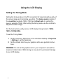
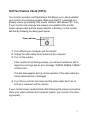
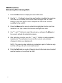
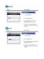
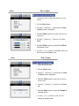
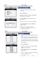
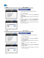
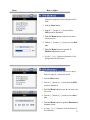
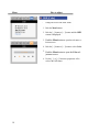
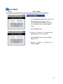
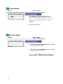
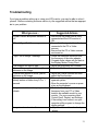
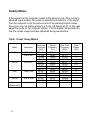
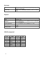
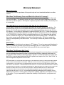
Hope Industrial Systems, Inc. User Manual 21.3” Panel Mount Industrial Monitor Model No. HIS-ML21-SGAB, HIS-ML21-SRAB 1 TABLE OF CONTENTS Safety and Regulatory Information ............................. 3 Using the LCD Display Setting the Timing Mode .................................... 4 Self-Test Feature Check .................................... 5 User Controls ..................................................... 6 Automatic Save .................................................. 7 Direct Access Features ...................................... 7 OSD Lock/Unlock ............................................... 7 OSD Functions ................................................... 8 Troubleshooting ............................................... 21 Display Modes .................................................. 22 Installation Instructions ............................................ 23 Cleaning................................................................... 25 Drawings .................................................................. 26 Specifications........................................................... 28 Warranty Statement ................................................. 31 2 Safety and Regulatory Information Warning To prevent fire or shock hazard, do not expose the unit to rain or moisture. Dangerously high voltages are present inside the unit. Do not disassemble the unit. Refer servicing to qualified personnel only. This equipment is not intended for use in critical applications where its failure to operate would create immediate life threatening circumstances. Applications including, but not limited to, nuclear reactor control, aerospace navigation systems and life support systems are not appropriate for this product. This product is intended to be mounted in a suitable cabinet or other enclosure. The NEMA 4, 4x or 12 ratings are applicable only when properly installed in a like rated enclosure. This product is a UL Recognized Component and must be used with a listed computer. FCC Notice This equipment has been tested and found to comply with the limits for a Class A digital device, pursuant to Part 15 of the FCC Rules. These limits are designed to provide reasonable protection against harmful interference when the equipment is operated in a commercial environment. This equipment generates uses and can radiate radio frequency energy and, if not installed and used in accordance with the instruction manual, may cause harmful interference to radio communications. Operation of this equipment in a residential area is likely to cause harmful interference in which case the user will be required to correct the interference at his own expense. Any changes or modifications not expressly approved by the grantee of this device could void the user’s authority to operate the device. 3 Using the LCD Display Setting the Timing Mode Setting the timing mode on the PC is important for maximizing the quality of the screen image and minimizing eye strain. The timing mode consists of the resolution (example 1280 x 1024) and refresh rate (or vertical frequency; example 75 Hz). After setting the timing mode, use the controls to adjust the screen image. For the best picture quality set your LCD display timing mode to: VESA 1600 x 1200 @ 60Hz. To set the Timing Mode: 1 2 Set the resolution: Right-click on the Windows desktop > Properties > Settings > set the resolution. Set the refresh rate: See your graphic card's user guide for instructions. WARNING: Do not set the graphics card in your computer to exceed the maximum refresh rate of 85Hz; doing so may result in permanent damage to your LCD display. 4 Self-Test Feature Check (STFC) Your monitor provides a self-test feature that allows you to check whether your monitor is functioning properly. Make sure that PC is selected as a primary source by checking if the source indicator LED labeled “PC” is on. If your monitor and computer are properly connected but the monitor screen remains dark and the power indicator is blinking, run the monitor self-test by following the steps given below: Power Indicator 1. Turn off both your computer and the monitor. 2. Unplug the video cable from the back of the computer. 3. Turn on the monitor. If the monitor is functioning properly, you will see a white box with a large blue oval logo and an error message “CHECK SIGNAL CABLE.” in black color. This box also appears during normal operation if the video cable becomes disconnected or damaged. 4. Turn off your monitor and reconnect the video cable; then turn on both your computer and the monitor. If your monitor screen remains blank after following the previous procedure, check your video controller and computer system; your monitor is functioning properly. 5 User Controls Your LCD monitor allows you to easily adjust the characteristics of the image being displayed. All of these adjustments are made using the control buttons on the rear of the monitor. While you use these buttons to adjust the controls, an OSD shows you their numeric values as they change. Rear Control Buttons and Indicators Button / Indicator Functions LED This light glows green during normal operation, and blinks green once as the monitor saves your adjustments. POWER Use this button to turn the monitor on and off. (When the power is turned on, a message appears in the center of the screen displaying the current mode – analog or digital input signal. MENU Use this button to open the OSD and activate a highlighted menu item. +,- These buttons allow you to highlight and adjust items in the menu. EXIT SOURCE AUTO 6 Use this button to Exit the active menu or the OSD. When you push the Source button while the OSD is off, the input source (analog/digital) is alternated. Use this button to automatically adjust the display to sync with the computer’s video signal. Automatic Save Whenever you open the OSD and allow an adjustment window to remain active for about 3 seconds without pressing other buttons, the monitor automatically saves any adjustment you have made. These changes are saved into a user area in the monitor. The monitor can save adjustments for up to 4 user modes. It has 13 factory preset or preload modes, one for each signal frequency. If you have made no adjustments, the on screen display disappears and the monitor does not save anything. Direct Access Features Brightness Adjustment 1. With the menu off, push the “-“ or “+” button to display the brightness adjustment menu. 2. Push the “+” button to increase the brightness; push the “-“ button to decrease the brightness. OSD Lock/Unlock This function allows you to secure the current settings so that they cannot be inadvertently changed, while still allowing you to adjust the Brightness and Contrast. You can unlock the OSD controls at any time by using the same procedure. With the OSD screen off, push and hold the Menu button for at least 5 seconds to lock or unlock the controls. When locked, a 'LOCKED!' message will be displayed along the bottom of each OSD menu except for these screens: o Brightness o Contrast 7 OSD Functions Accessing the menu system 1. Push the Menu button to display the main OSD menu. 2. Use the "– , +" buttons to move from one function to another. As you move from one icon to another, the Function Name changes. See the Table starting on the next page to view a complete list of all of the functions available for the monitor. 3. Press the Menu button once to activate the highlighted function and then follow the Tool Tips to select the function and adjust the value. 4. Use "–" and "+" buttons to select the sub-menu, and press the Menu button once to activate the selected sub-menu. 5. After selecting a function, use the "–" and "+" buttons to make necessary adjustments. The setting bar moves and the numeric value indicator changes to reflect your adjustments. NOTE: The numeric value indicator is provided as a point of reference only and has nothing to do with a real measurement. 6. Push the Exit button a couple of times to return to the main menu to select another function or to exit from the OSD. 8 Menu How to adjust - Adjust Brightness 1. Push the Menu button. 2. Push the Menu button to open the Brightness adjustment screen. 3. Use the [ + ] button to increase the brightness or [ - ] button to decrease the brightness. Menu How to adjust - Adjust Contrast 1. Push the Menu button. 2. Push the Menu button to open the Contrast adjustment screen. 3. Use the [ + ] button to increase the brightness or [ - ] button to decrease the brightness. 9 Menu How to adjust - Removes noise such as vertical stripes. Coarse adjustment may move the screen image area. You may relocate it to the center using the Horizontal Control menu. 1. Push the Menu button. 2. Push the [ - ] button or [ + ] button until the Image screen is displayed. 3. Push the Menu button to open the sub-menu selection screen. 4. Push the [ - ] button or [ + ] button to select the Coarse. 5. Push the Menu button to open the Coarse adjustment screen. 6. Use the [ - ] or [ + ] buttons to adjust the coarse. Menu How to adjust - Removes noise such as horizontal stripes. If the noise persists even after Fine tuning, repeat it after adjusting the frequency (clock speed). 1. Push the Menu button. 2. Push the [ - ] button or [ + ] button until the Image screen is displayed. 3. Push the Menu button to open the sub-menu selection screen. 4. Push the [ - ] button or [ + ] button to select the Fine. 5. Push the Menu button to open the Fine adjustment screen. 6. Use the [ - ] or [ + ] buttons to adjust the coarse. 10 Menu How to adjust - Follow these instructions to change the horizontal position of the monitor’s entire display. 1. Push the Menu button. 2. Push the [ - ] button or [ + ] button until the Image screen is displayed. 3. Push the Menu button to open the sub-menu selection screen.1 4. Push the [ - ] button or [ + ] button to select the H-Position. 5. Push the Menu button to open the H-Position adjustment screen. 6. Use the [ - ] or [ + ] buttons to the horizontal position of the monitor’s viewing area. Menu How to adjust - Follow these instructions to change the vertical position of the monitor’s entire display. 1. Push the Menu button. 2. Push the [ - ] button or [ + ] button until the Im- age screen is displayed. 3. Push the Menu button to open the sub-menu selection screen. 4. Push the [ - ] button or [ + ] button to select the V-Position. 5. Push the Menu button to open the V-Position adjustment screen. 6. Use the [ - ] or [ + ] buttons to the horizontal position of the monitor’s viewing area. 11 Menu How to adjust - Image being displayed can be made to Sharpen, Medium or Soften. 1. Push the Menu button. 2. Push the [ - ] button or [ + ] button until the Image screen is displayed. 3. Push the Menu button to open the submenu selection screen. 4. Push the [ - ] button or [ + ] button to select the Image Effect. 5. Push the Menu button to open the Image Effect selection screen. 6. Use the [ - ] or [ + ] buttons to select Sharpen or Medium or Soften. 12 Menu How to adjust - Bluish White 1. Push the Menu button. 2. Push the [ - ] button or [ + ] button until the Color Control screen is displayed. 3. Push the Menu button to open the submenu selection screen. 4. Push the [ - ] button or [ + ] button to select Bluish. 5. Push the Menu button to adjust Bluish white. Menu How to adjust - Bluish White 1. Push the Menu button. 2. Push the [ - ] button or [ + ] button until the Color Control screen is displayed. 3. Push the Menu button to open the submenu selection screen. 4. Push the [ - ] button or [ + ] button to select Reddish. 5. Push the Menu button to adjust Bluish white. 13 Menu How to adjust - Follow these steps to adjust individual R,G,B color control. 1. Push the Menu button. 2. Push the [ - ] button or [ + ] button until the Color Control screen is displayed. 3. Push the Menu button to open the sub-menu selection screen. 4. Push the [ - ] button or [ + ] button to select User Mode. 5. Push the Menu button to open the User Mode adjustment screen. 6. Use the [ - ] or [ + ] button to select R(ed), G(reen) or B(lue) and push the Menu button. Menu How to adjust - Adjust the gamma value. 1. Push the Menu button. 2. Push the [ - ] button or [ + ] button until the Color Control screen is displayed. 3. Push the Menu button to open the sub-menu selection screen. 4. Push the [ - ] button or [ + ] button to select Gamma. 5. Push the Menu button to open the Gamma ad- justment screen. 6. Use the [ - ] or [ + ] button to select 1, 2, 3 to 14 change the gamma value. Menu How to adjust - Color parameters are replaced with the factory default values. 1. Push the Menu button. 2. Push the [ - ] button or [ + ] button until the Color Control screen is displayed. 3. Push the Menu button to open the sub-menu selection screen. 4. Push the [ - ] button or [ + ] button to select Reset. 5. Push the Menu button to open the Reset ad- justment screen. 6. Use the [ - ] or [ + ] button to select Yes. If you don’t want to reset the monitor, use the [ - ] or [ + ] button to select No. Menu How to adjust - Follow these steps to change the language used in the menu. You can choose one of seven languages. (English, German, Spanish, French, Italian, Swedish, Russian) Note: the language chosen affects only the language of the OSD. It has no effect on any software running on the computer. 1. Push the Menu button. 2. Push the [ - ] button or [ + ] button until the Lan- guage screen is displayed. 3. Push the Menu button to open the Language selection screen. 4. Use the [ - ] button or [ + ] button to select the lan- guage you would like to use. 5 P h th M b tt t 15 th G d Menu How to adjust - Change the horizontal position of the OSD menu 1. Push the Menu button. 2. Push the [ - ] button or [ + ] button until the OSD screen is displayed. 3. Push the Menu button to open the sub-menu selection screen. 4. Push the [ - ] button or [ + ] button to select H-Position. 5. Push the Menu button to open the H-Position ad- justment screen. 6. Use the [ - ] or [ + ] button to change the horizontal position of the OSD menu. Menu How to adjust - Change the horizontal position of the OSD menu 1. Push the Menu button. 2. Push the [ - ] button or [ + ] button until the OSD screen is displayed. 3. Push the Menu button to open the sub-menu selection screen. 4. Push the [ - ] button or [ + ] button to select VPosition. 5. Push the Menu button to open the V-Position ad- justment screen. 6. Use the [ - ] or [ + ] button to change the vertical position of the OSD menu. 16 Menu How to adjust - Change the opaqueness of the background of the OSD. 1. Push the Menu button. 2. Push the [ - ] button or [ + ] button until the OSD screen is displayed. 3. Push the Menu button to open the sub-menu selection screen. 4. Push the [ - ] button or [ + ] button to select Halftone. 5. Push the Menu button to open the V- Halftone adjustment screen 6. Use the [ - ] or [ + ] button to opaqueness of the background of the OSD menu. - The menu will automatically turn off if no adjustments are made for a certain time period. 1. Push the Menu button. 2. Push the [ - ] button or [ + ] button until the OSD screen is displayed. 3. Push the Menu button to open the sub-menu selection screen. 4. Push the [ - ] button or [ + ] button to select Duration. 5. Push the Menu button to open the Duration ad- justment screen 6. Use the [ - ] or [ + ] button to select the duration of the OSD menu. 17 Menu How to adjust - Change the color of the OSD. menu. 1. Push the Menu button. 2. Push the [ - ] button or [ + ] button until the OSD screen is displayed. 3. Push the Menu button to open the sub-menu selection screen. 4. Push the [ - ] button or [ + ] button to select Color. 5. Push the Menu button to open the Color ad- justment screen 6. Use the [ - ] or [ + ] button to opaqueness of the color of the OSD menu. 18 Menu How to adjust - Select Auto Source Select for the monitor to automatically select the signal source. Select Manual Source Select to manually select the signal source using the Source button. 1. Push the Menu button. 2. Push the [ - ] button or [ + ] button until the Source Select screen is displayed. 3. Push the Menu button to open the Source Select screen. 4. Push the [ - ] button or [ + ] button to select Auto or Manual. 19 Menu How to adjust - Auto adjustment allows the monitor to selfadjust to the incoming video signal. The values of fine, coarse and position are adjusted automatically. 1. Push the Auto button. Menu How to adjust 1. Push and hold in the Menu button for 5 seconds or more to Lock the OSD. 2. Push and hold in the Menu button for 5 seconds or more to Unlock the OSD. * You can adjust the Brightness and Contrast settings even after you have locked the OSD menu. 20 Troubleshooting If you have a problem setting up or using your LCD monitor, you may be able to solve it yourself. Before contacting customer service, try the suggested actions that are appropriate to your problem. What you see… Suggested Actions Ensure that the power cord is firmly connected and the LCD monitor is ON. “Check Signal Cable” message Ensure that the signal cable is firmly connected to the PC or Video sources. Ensure that the PC or Video sources are turned on. “Sync. Out of Range” message Check the maximum resolution and the frequency of the video adapter. Compare these values with the data in the Display Modes Timing Chart. The image is too light or dark Adjust the Brightness and Contrast. Horizontal bars appear to flicker, jitter or Adjust the Fine function. shimmer on the image Vertical bars appear to flicker, jitter or Adjust the Coarse function and then shimmer on the image adjust the Fine function. Screen is blank and the power light is The monitor is using its power mansteady amber or blinks every 0.5 or 1 agement system Move the computer’s mouse or press second. a key on the keyboard Image is not stable and may appear to Check that the display resolution and vibrate frequency from your PC or Video board is an available mode for your monitor. On your computer check Control Panel, Display, and Settings. If the setting is not correct, use your computer utility program to change the display settings. Image is not centered on the screen Adjust the horizontal and vertical positions Screen is blank and power indicator is off 21 Display Modes If the signal from the computer system is the same as one of the monitor’s standard signal modes, the screen is adjusted automatically. If the signal from the computer is not the same as one of the standard signal modes, the screen may not display properly or it may not display at all. In this case adjust the mode on the computer system. For the display modes listed below, the screen image has been optimized during manufacture. Table: Preset Timing Modes Mode Resolution VGA 720 x 400 640 x 480 SVGA 800 x 600 XGA 1024 x 768 SXGA 1280 x 1024 UXGA (Analog Only) 1600 x 1200 22 Horizontal Frequency (kHz) Vertical Frequency (Hz) Pixel Clock Frequency (MHz) Sync Polarity (H/V) 31.469 31.469 37.500 37.861 46.875 35.156 37.879 48.077 48.363 60.023 56.476 63.981 79.976 75.000 70.087 59.940 75.000 72.809 75.000 56.250 60.317 72.188 60.004 75.029 70.069 60.020 75.025 60.000 28.322 25.175 31.500 31.500 49.500 36.000 40.000 50.000 65.000 78.750 75.000 108.000 135.000 162.000 -/+ -/-/-/+/+ +,-/+,+/+ +/+ -/+/+ -/-/-/+/+ Installation Instructions Preparing for Installation Important! Perform the following steps BEFORE Installation of the monitor into the panel. 1. Ensure that sufficient power is available. 2. Ensure that sufficient space is available to allow for proper airflow into and out of the unit. 3. Ensure that the air temperature around the unit (top and bottom) will not exceed the rated specifications of the unit. The maximum rated temperature of the HIS-ML21 is 50°C (122°F) with the fan kit installed and with use of an equally rated power supply. Remember that heat rises – the temperature at the top of the cabinet will be much hotter than at the bottom when the air is not circulating. Also, remember that even though this product is designed to operate at 50°C with proper ventilation, the life span of any electronic device is shortened when it is consistently operated at high temperatures. Therefore it is wise to take steps to keep the temperature of the ambient air around the unit as low as possible. 4. Ensure that the ambient humidity of the air around the unit does not exceed the rated specifications for the unit The maximum rated humidity for the HIS-ML21 is 80% non-condensing 23 Installation into Panel 1. Refer to the drawing below. 2. Locate position in panel for mounting of the monitor. Assure that there is adequate space begin the panel. Allow extra space (0.5 in. behind and on each side) for air ventilation. 3. Cut a rectangular hole in the panel. Clean and deburr. Dimensions: 21.13” (536mm) W x 16.70” (424mm) H ; +/- .020” 4. Separate the rear collar from the unit by removing the 14 nuts. 5. Insert the unit into the front of the panel and re-attach the collar. 6. Tighten all 14 nuts to a torque of 24 inch-pounds to assure a water-tight seal between the poron bezel gasket on the monitor and equipment panel. HIS will not assume liability for damage to internal electronics due to improper installation. 24 Cleaning Any standard glass cleaner can be used to clean the touchscreen or protective safety glass window. Always spray the glass cleaner on the cloth or towel and then clean the touchscreen. Glass cleaner sprayed directly on the monitor could possibly leak inside a non-sealed unit and cause damage. Vinegar or ammonia will not hurt the touchscreen. Again, spray the cloth and then clean the touchscreen. 25 Drawings Front View Bottom and Rear View (Showing cutout dimensions) 26 27 Specifications Display Type Size Image size Native resolution Plug and Play Minimum resolution Pixel pitch Number of colors Viewing Angle (Hori/Vert) Brightness (white) Contrast ratio Back light Screen protector (when not shipped with touchscreen) Thin-film transistor (TFT) Active Matrix Liquid Crystal 21.3” diagonal 17.00” (432mm) x 12.75” (324mm) SXGA (1600 x 1200) @ 60 Hz DDC1/2B compatible VGA (640 x 480), operation in native resolution will ensure best results 0.27mm (H) x 0.27 mm (V) 16M (24 bit) 170° / 170°, typical 2 250 nits (cd/m ) 500:1 6 CCFTs (Cold Cathode Fluorescent Tube) Tempered glass to ANSI-Z97.1 SPEC; AR coated on both sides; 98% Transmission of light; 99% Reduction of glare; 53% UV blocking; 30% NIR Blocking; proprietary hydrophobic coating on outside reduces fingerprint smears, repels liquid spills and makes glass easy to clean. Video Input connector Input signal format HD-15 plus DVI digital input Analog RGB signals, DVI Analog/Digital Horizontal scan Vertical scan 30kHz – 81kHz VGA (640 x 480), SVGA (800 x 600), XGA (1024 x 768), SXGA (1280 x 1024), UXGA (1600 x 1200) Note: Native mode is 1600 x 1200 50 Hz – 75 Hz Response rate (typical) 25ms Supported Video Standards 28 Electrical Monitor input 85-132 VAC / 170-265 VAC (47-63 Hz) Power consumption Power management Compliance 75 watts (max.) DPMS/energy star, < 5W UL 1950, cUL 959; FCC Class A Environmental Temperature Humidity Shock Vibration Altitude 0-50°C (with fan kit and equally rated power supply) 10% to 80% non-condensing 30g (1/2 sine, 11 msec.) 0.006 inch p-p 15-57Hz, 1.0g 57-640Hz sine Operating: up to 10,000 feet; Non-operating: up to 40,000 feet Functional Panel controls (rear access) OSD (On Screen Display) controls Power, Menu, +, -, Exit, Auto Touch screen option 5-wire resistive system; emulates a mouse; DB-9, RS-232 interface to host computer Auto image adjust, contrast, brightness, color adjust (9300K, 6500K-default, 5400K, 5000K, user color), manual image adjust (H/V size/position, fine tune, sharpness, scaling), setup menu (language, resolution notice, OSD position, OSD timeout, OSD background), memory recall) 29 Enclosure Type Panel mount; rear collar compresses gasket against panel, held by 14 10-32 studs NEMA 12/4/4X (with proper installation) – built to IP65 standards Panel rating Physical Depth Bezel Front bezel outside dimensions 2.01” (51mm) behind panel, fan kit adds another 1.1” Stainless Steel 22.28” (566mm) W x 17.87” (454mm) H x 0.28” (7mm) thick (not including gasket) Cutout dimensions 21.13” (537mm) W x 16.70” (424mm) H ; +/- .020” Net weight 31 lbs. Shipping weight 39 lbs. VGA Pin assignment Pin No. 1 2 3 4 5 6 7 8 30 Signal Red Green Blue Ground Ground Ground Ground Ground Pin No. 9 10 11 12 13 14 15 Signal No pin Ground Ground SDA H. sync V. sync SCL Warranty Statement Who is Covered? This warranty covers the purchaser of this product only and is not transferable without our written consent. What Does This Warranty Cover and What is the Period of Coverage? We warrant this product to be free from defects in material and workmanship, subject to the conditions set forth below. This warranty remains in force for a three-year period beginning on the date we invoice you for the product. If HIS repairs or replaces a product under warranty, its warranty term is not extended. What Will We Do to Correct Problems and How Do You Get Service? We will repair or replace (at our sole option) any part of the unit which proves to be defective. Replacement parts may be new or refurbished and will meet the same specifications of the original parts or unit. We will return the product to you, by the shipping method we choose in the U.S.A. at our expense. You must pay for shipments to locations outside of the U.S.A. In order to receive warranty service you must get prior approval from HIS. To request warranty service you can telephone us at 770-992-0297 or send an email to [email protected]. If we determine that warranty service is needed we will give you a Return Material Authorization (RMA) number. This RMA number must be conspicuously marked on the outside of the shipping box. HIS will not accept shipments not accompanied by the RMA number. You must ship or deliver the product to HIS Freight prepaid. Pixel Faults Permanently dark or bright pixels can happen to TFT displays. Five or less permanently dead pixels (out of 1.3 million) do not make a good case for exchanging the unit. Please contact our Customer Service Department if the number of pixel faults exceeds the above-mentioned figure. What Does This Warranty Not Cover? This warranty does not cover equipment which has been damaged due to misuse, abuse or accident such as: operating the equipment outside of published specifications; displaying fixed images for long periods of time resulting in afterimage effects; improper or unauthorized repair by anyone other than HIS or a service agency authorized by HIS to perform such repairs; fire, flood, “acts of God”, or other contingencies beyond the control of HIS. HIS’ RESPONSIBILITY FOR MALFUNCTIONS AND DEFECTS IN HARDWARE IS LIMITED TO REPAIR AND REPLACEMENT AS SET FORTH IN THIS WARRANTY STATEMENT. HIS SHALL NOT BE LIABLE FOR DIRECT, INDIRECT, INCIDENTAL, CONSEQUENTIAL, OR OTHER TYPES OF DAMAGES RESULTING FROM THE USE OF ANY HIS PRODUCT OTHER THAN THE LIABILITY STATED ABOVE. THESE WARRANTIES ARE IN LIEU OF ALL OTHER WARRANTIES EXPRESS OR IMPLIED, INCLUDING, BUT NOT LIMITED TO, THE IMPLIED WARRANTIES OF MERCHANTABILITY OR FITNESS FOR A PARTICULAR PURPOSE. SOME STATES DO NOT ALLOW THE EXCLUSION OF IMPLIED WARRANTIES OR THE LIMITATION OR EXCLUSION OF LIABILITY FOR INCIDENTAL OR CONSEQUENTIAL DAMAGES SO THE ABOVE EXCLUSIONS OR LIMITATIONS MAY NOT APPLY TO YOU. You are cautioned that the performance of this product can be affected by many factors, such as system configuration, software, application, and operator control of the system. It is your responsibility to determine suitability of this product for your purpose and application. 31 Hope Industrial Systems, Inc. 1325 Northmeadow Parkway Suite 100 Roswell, GA 30076 www.HISmonitors.com Publication ML21-1.0 March 2003 32 2003 Hope Industrial Systems, Inc.