1
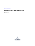
RWZ01 Magneto–Optical Disk Subsystem digi tal Maintenance Guide Part Number: EK–RWZ01–MG–002 RWZ01 Magneto–Optical Disk Subsystem Maintenance Guide Part Number: EK–RWZ01–MG–002 Prepared by U.S. Area EIC Documentation Services Digital Equipment Corporation • Merrimack, NH 03054 June 1991 The information in this document is subject to change without notice and should not be construed as a commitment by Digital Equipment Corporation. Digital Equipment Corporation assumes no responsibility for any errors that may appear in this document. The software described in this document is furnished under a license and may be used or copied only in accordance with the terms of such license. No responsibility is assumed for the use or reliability of software on equipment that is not supplied by Digital Equipment Corporation or its affiliated companies. Restricted Rights: Use, duplication, or disclosure by the U.S. Government is subject to restrictions as set forth in subparagraph (c)(1)(ii) of the Rights in Technical Data and Computer Software clause at DFARS 252.227-7013. Copyright ©1991 by Digital Equipment Corporation. All Rights Reserved. Printed in Japan The postpaid READER’S COMMENTS form on the last page of this document requests the user’s critical evaluation to assist in preparing future documentation. The following are trademarks of Digital Equipment Corporation DEC VAXBI VT DECUS VAXcluster ULTRIX PDP VAXELN VAXstation VAX VMS DECstation The DIGITAL Logo This document was prepared using VAX DOCUMENT, Version 2.0. iii This apparatus complies with the Class A limits for radio noise emissions set out in Radio Interference Regulations of Canada. iv This device complies with the standard of Information Device Wave Failure Self−Regulation Association (VCCI) to prevent wave failure occuring in the Type 1 information devices (information devices used in the commerical and industrial areas). Therefore, if the device is used in a location adjacent to residential areas, reception problems may occur in radio or television receivers. The device must be handled correctly according to the manual. v Für Bundesrepublik Deutschland und Berlin (West) For Federal Republic of Germany and West Berlin Pour la République féderale d’Allemagne et Berlin Ouest Bescheinigung des Herstellers/Importeurs Hiermit wird bescheinigt, daß die Einrichtung in Übereinstimmung mit den Bestimmungen der DBP-Verfügung 1046/84, Amtsblatt Nr. 163/1984, und Grenzwertklasse "B" der VDE0871, funkenstört ist. Der Deutschen Bundespost (DBP) wurde das Inverkehrbringen dieses Gerätes angezeigt und die Berechtigung zur Überprüfung der Serie auf Einhaltung der Bestimmungen eingeräumt. Betreiberhinweis Wir sind verpflichtet, Sie auf folgende Fakten hinzuweisen (DBP-Verfügung 1046/84, §2, Abschnitt 5): Das Gerät wurde funktechnisch sorgfältig entstört und geprüft. Beim Zusammenschalten mit anderen EDV-Geräten können im ungünstigsten Fall Funkstörungen entstehen, die dann im Einzelnen zusätzliche Funkenstörungs-Maßnahmen durch den Benutzer erfordern. Externe Datenkabel Sollte ein Austausch der von Digital spezifizierten Datenkabel nötig werden, muß der Betreiber für eine einwandfreie Funkentstörung sicherstellen, daß Austauschkabel im Aufbau und Abschirmqualität dem Digital Originalkabel entsprechen. vi vii viii Contents Preface xiii Chapter 1 Overview 1.1 1.2 1.3 Features . . . . . . . . . . . . . . . . . . . . . . . . . . . . . . . . . . . . . . . . . . . . . 1–1 System Configuration . . . . . . . . . . . . . . . . . . . . . . . . . . . . . . . . . . . 1–2 Writing and Reading Data in the RWZ01 . . . . . . . . . . . . . . . . . . . . 1–2 Chapter 2 System Description of the RWZ01 2.1 2.2 2.3 2.4 2.5 2.6 2.7 Internal Structure of the RWZ01 . . . . . . . . . . . . . . . . . . . . . . . . . . 2–1 2.1.1 Disk Drive Section . . . . . . . . . . . . . . . . . . . . . . . . . . . . . . 2–1 2.1.2 SCSI Controller . . . . . . . . . . . . . . . . . . . . . . . . . . . . . . . . 2–4 2.1.3 Front View of the RWZ01 . . . . . . . . . . . . . . . . . . . . . . . . . 2–7 2.1.4 Rear View of the RWZ01 . . . . . . . . . . . . . . . . . . . . . . . . . 2–8 Connecting the RWZ01 . . . . . . . . . . . . . . . . . . . . . . . . . . . . . . . . . . 2–9 System Configuration . . . . . . . . . . . . . . . . . . . . . . . . . . . . . . . . . . 2–11 Checking a SCSI ID Number . . . . . . . . . . . . . . . . . . . . . . . . . . . . 2–11 2.4.1 Operation for VMS . . . . . . . . . . . . . . . . . . . . . . . . . . . . . 2–12 2.4.2 Operation for ULTRIX . . . . . . . . . . . . . . . . . . . . . . . . . . 2–12 Setting Switchpack Switches . . . . . . . . . . . . . . . . . . . . . . . . . . . . 2–12 2.5.1 Setting Switches for Operating Parameters . . . . . . . . . . 2–13 2.5.2 Setting a SCSI ID Number . . . . . . . . . . . . . . . . . . . . . . 2–15 Changing the /etc/disktab File (ULTRIX) . . . . . . . . . . . . . . . . . . . 2–16 Creating the Special File (ULTRIX) . . . . . . . . . . . . . . . . . . . . . . . 2–17 ix 2.8 Changing Partition Sizes (ULTRIX) . . . . . . . . . . . . . . . . . . . . . . . 2–17 Chapter 3 How to Handle Failures 3.1 3.2 3.3 3.4 General Failure . . . . . . . . . . . . . . . . . . . . . . . . . . . . . . . . . . . . . . . 3–1 Error Codes . . . . . . . . . . . . . . . . . . . . . . . . . . . . . . . . . . . . . . . . . . 3–5 3.2.1 Operation for VMS . . . . . . . . . . . . . . . . . . . . . . . . . . . . . . 3–5 3.2.2 Operation for ULTRIX . . . . . . . . . . . . . . . . . . . . . . . . . . . 3–6 3.2.3 Sense Key Status Messages . . . . . . . . . . . . . . . . . . . . . . . 3–6 3.2.4 Additional Sense Code Status Messages . . . . . . . . . . . . . 3–7 VAXstation ROM Diagnosis Test . . . . . . . . . . . . . . . . . . . . . . . . . 3–13 Operation for DECstation . . . . . . . . . . . . . . . . . . . . . . . . . . . . . . 3–13 Chapter 4 Maintenance 4.1 4.2 4.3 Cautions on Use . . . . . . . . . . . . . . . . . . . . . . . . . . . . . . . . . . . . . . . 4–1 Disk . . . . . . . . . . . . . . . . . . . . . . . . . . . . . . . . . . . . . . . . . . . . . . . . 4–3 4.2.1 Data Protection Switch (Tab) . . . . . . . . . . . . . . . . . . . . . . 4–3 4.2.2 Condensation . . . . . . . . . . . . . . . . . . . . . . . . . . . . . . . . . . 4–3 4.2.3 Disk Storage . . . . . . . . . . . . . . . . . . . . . . . . . . . . . . . . . . 4–3 Cleaning an Optical Head . . . . . . . . . . . . . . . . . . . . . . . . . . . . . . . 4–3 Appendix A Specifications A.1 A.2 Specifications of the RWZ01 . . . . . . . . . . . . . . . . . . . . . . . . . . . . . A–1 Specifications of the Disk . . . . . . . . . . . . . . . . . . . . . . . . . . . . . . . A–3 Appendix B Parts List x Appendix C Regulations C.1 C.2 Safety . . . . . . . . . . . . . . . . . . . . . . . . . . . . . . . . . . . . . . . . . . . . . . C–1 EMC . . . . . . . . . . . . . . . . . . . . . . . . . . . . . . . . . . . . . . . . . . . . . . . C–1 Appendix D Theory of Laser Optical Disks D.1 D.2 D.3 D.4 D.5 Principle of Writing Data to and Reading Data from a Disk D.1.1 Write Principle . . . . . . . . . . . . . . . . . . . . . . . . . . . . D.1.2 Read Principle . . . . . . . . . . . . . . . . . . . . . . . . . . . . Disk Format . . . . . . . . . . . . . . . . . . . . . . . . . . . . . . . . . . . . . Format Specifications . . . . . . . . . . . . . . . . . . . . . . . . . . . . . . D.3.1 Modulation Code . . . . . . . . . . . . . . . . . . . . . . . . . . D.3.2 Sector Format . . . . . . . . . . . . . . . . . . . . . . . . . . . . Data Field Format . . . . . . . . . . . . . . . . . . . . . . . . . . . . . . . . Defect Management Strategies . . . . . . . . . . . . . . . . . . . . . . D.5.1 Sector Slipping Algorithm . . . . . . . . . . . . . . . . . . . D.5.2 Linear Replacement Algorithm . . . . . . . . . . . . . . . . . . . . . . . . . . . . . . . . . . . . . . . . . . . . . . . . . . . . . . . . . . . D–1 D–2 D–3 D–3 D–4 D–4 D–4 D–5 D–5 D–5 D–6 . . . . . . . . . . . . . . . . . . . . . . . . . . . . . . . . . . . . . . . . . . . . . . . . . . . . . xvi . 1–2 . 2–2 . 2–5 . 2–7 . 2–8 2–10 2–11 2–12 2–13 2–14 2–14 2–15 Index Figures 1 1–1 2–1 2–2 2–3 2–4 2–5 2–6 2–7 2–8 2–9 2–10 2–11 The RWZ01 Disk Drive . . . . . . . . . . . . . . . . . . Typical System Configuration . . . . . . . . . . . . . RWZ01 Disk Drive Modules . . . . . . . . . . . . . . . Structure of the RWZ01 SCSI Controller . . . . . Front of the RWZ01 Disk Drive . . . . . . . . . . . . Rear of the RWZ01 Disk Drive . . . . . . . . . . . . . Connection of the RWZ01 . . . . . . . . . . . . . . . . . Typical VAXstation 3100 System Configuration SCSI ID Number Examples . . . . . . . . . . . . . . . Setting the RWZ01 Switchpack Switches . . . . When a Terminator is Used . . . . . . . . . . . . . . . When a Terminator is not Used . . . . . . . . . . . . Setting the SCSI ID Number . . . . . . . . . . . . . . xi . . . . . . . . . . . . . . . . . . . . . . . . . . . . . . . . . . . . . . . . . . . . . . . . . . . . 3–1 3–2 4–1 D–1 D–2 D–3 D–4 D–5 Ejecting a Disk in an Emergency . . . . . . . . . . . . . . . Disk Data Protection Switch (Tab) . . . . . . . . . . . . . . Lens Cleaning Cartridge . . . . . . . . . . . . . . . . . . . . . Principle of Writing Data to a Disk . . . . . . . . . . . . . Principle of Reading Data from a Disk . . . . . . . . . . . Disk Format . . . . . . . . . . . . . . . . . . . . . . . . . . . . . . . Sector Slipping Algorithm . . . . . . . . . . . . . . . . . . . . Structure of Bands, Linear Replacement Algorithm . . . . . . . . . . . . . . . . . . . . . . . . . . . . . . . . . . 3–4 . 3–5 . 4–4 D–2 D–3 D–4 D–6 D–7 Notes, Cautions, Warnings - Documentation Cautions, Warnings - Safety . . . . . . . . . . . . . SCSI ID Number Switch Settings . . . . . . . . General Failures and Corrective Action . . . . Sense Keys . . . . . . . . . . . . . . . . . . . . . . . . . . Additional Sense Codes . . . . . . . . . . . . . . . . RWZ01 Parts List . . . . . . . . . . . . . . . . . . . . SCSI Cable List . . . . . . . . . . . . . . . . . . . . . . Power Cords List . . . . . . . . . . . . . . . . . . . . . . . . . . . . . . . . . . . . . . . . . . . . . . . . . . . . . . . . . . . xv . . xv 2–16 . 3–1 . 3–6 . 3–8 B–1 B–2 B–2 Tables 1 2 2–1 3–1 3–2 3–3 B–1 B–2 B–3 xii . . . . . . . . . . . . . . . . . . . . . . . . . . . . . . . . . . . . . . . . . . . . . . . . . . . . . . Preface This manual describes the RWZ01 Magneto-Optical Disk Drive (hereafter call the RWZ01 Disk Drive or the RWZ01), handling possible RWZ01 failures, and maintenance of the RWZ01. Document Structure Chapter 1, Overview - Outlines the functions and principles of the RWZ01. Chapter 2, System Description of the RWZ01 - Describes the internal structure, name and function of each part, and system configuration of the RWZ01. Chapter 3, How to Handle Failures - Describes how to detect the cause and action to be taken when a failure occurs in the RWZ01. Chapter 4, Maintenance - Describes how to clean disks and lenses in the RWZ01. Appendix A, Theory of Laser Optical Disks - Describes the write and read operations in optical laser disks and defect management strategies. Appendix B, Specifications - Provides a summary of specifications of the RWZ01, disks, and attachments. Appendix C, Parts List - Lists the parts available for the RWZ01 Disk Drive. xiii Appendix D, Regulations - Lists the regulations with which the RWZ01 is compatible. How to Use This Manual Read Chapter 1 to understand the outline and principle of the RWZ01. Then, read Chapter 2 to become familiar with the internal structure, and the name and function of each part of the RWZ01. If a failure occurs, read Chapter 3 to diagnose the cause. Read Chapter 4 for regular maintenance of the RWZ01. The RWZ01 can be installed by a customer using the RWZ01 Magneto-Optical Disk Subsystem User’s Guide. Use the appendices as required. Intended Audience This manual is intended for Digital Customer Service personnel who are to maintain the RWZ01. Related Manuals The following related manuals are available for the RWZ01. • VAXstation Maintenance Guide • RWZ01 Magneto-Optical Disk Subsystem User’s Guide • Lens Cleaning Cartridge User’s Manual The following manuals provide additional information on the environment in which the RWZ01 Disk Drive is used, and may help in your understanding of this manual. • Owner’s Manual/User’s Guide of each host computer • VMS System Manager’s Manual • ULTRIX Guide to Disk Maintenance • ULTRIX Reference Volume • ULTRIX Guide to Error Logger • DECstation Operator’s Guide xiv Conventions The following conventions are used in this manual: Table 1: Notes, Cautions, Warnings - Documentation NOTE Calls the attention to any item of information that may be of special importance to the reader. CAUTION Contains essential information to avoid damage to the equipment. WARNING Contains essential information for the safety of the user. Table 2: Cautions, Warnings - Safety DANGER Serious injury or death is imminent if you continue in this direction. WARNING Injury is imminent if you continue in this direction. CAUTION Injury is possible if you continue in this direction. ATTENTION (NOTE) Damage to the equipment can occur if you continue in this direction. xv Figure 1: The RWZ01 Disk Drive xvi Chapter 1 Overview This chapter contains an overview of the features and functions of the RWZ01 Disk Drive (see Figure 1). 1.1 Features The RWZ01 Disk Drive is an external storage device that uses high capacity removable disks and has the following features: • A write/read disk that uses magneto-optical recording with a multiple write capability. • A high information capacity disk which has 590M bytes, 512 bytes /sector (excluding alternate areas). • A disk format which complies with the Continuous/Composite Servo (CS) format (ISO/IEC DIS 10089) of International Standard Organization (ISO), which is the world standard. • A Small Computer System Interface (SCSI) which complies with ANSI X3.131-1986 CCS Rev.4B. Up to eight units, including a host computer, can be connected to one SCSI bus. • A high-speed transmission of data that uses a high-speed spindle motor (2400 rpm). Overview 1–1 • A fast seek time of 95 ms that uses a thin, light-weight optical pickup. • An error correction that uses Long Distance Code. 1.2 System Configuration The RWZ01 is Small Computer System Interface (SCSI) compatible and therefore can be connected to the host computer SCSI bus. In addition, the RWZ01 can be connected to any SCSI unit in a system. Figure 1-1 shows a typical system configuration. (A SCSI terminator (terminal resistance) is built into the RWZ01 Disk Drive.) Figure 1–1: Typical System Configuration 1.3 Writing and Reading Data in the RWZ01 Writing and reading data in the RWZ01 is based on controlling the magnetic bits on the disk with a laser beam. Writing data is a two step process where the area to be written is first cleared (data is erased) and then the data is written. Reading data is based on sensing the magnetic polarity of the data bit by sensing the phase of the reflected laser beam. For details on the erase, write and read operations, see Appendix A. 1–2 Overview Chapter 2 System Description of the RWZ01 This chapter describes: • The internal structure of the RWZ01 • The name and function of each part of the RWZ01 that is accessible to the user • The system configuration of the RWZ01 2.1 Internal Structure of the RWZ01 The RWZ01 consists of a disk drive section and a SCSI controller section. The disk drive section controls the writing of data to and the reading of data from the disk. The SCSI controller section controls data flow between the host computer and the disk drive section. 2.1.1 Disk Drive Section The disk drive section of the RWZ01 includes mechanical, electrical and optical modules. These modules are shown in block diagram form in Figure 2-1 and are described in the following. System Description of the RWZ01 2–1 Figure 2–1: RWZ01 Disk Drive Modules 2–2 System Description of the RWZ01 1. Optical Head Module - This module includes a laser diode, a laser diode driver and a radio frequency (RF) servo amplifier. The laser diode is used to erase and read data from the disk and to write data to the disk. 2. Laser Diode Driver/Data Separation Module - This module has two major areas: • Using an automatic power control (APC) unit, the laser diode drive sets the power level. This power level is set according to the operating mode (erase, write, or read). APC tests the output of Write and Erase of the automatic laser power control (ALPC) area and maintains the required output level. • Photo detector output signals are divided into two different bandwidth signals for the data separation and the servo systems. The RF signal is differentially amplified for peak detection of data and is equalized. The phase locked oscillator (PLO) generates a phase-locked clock to separate data. A demodulator uses the PLO to decode the (2,7) run length limited (RLL). 3. Servo Module - This module has four submodules: • Spindle Servo Submodule - This submodule rotates the disk at 2400 rpm using a digital frequency-lock servo method. • Focus Servo Submodule - This submodule focuses a laser beam on the disk writing surface by controlling the dual-axis actuator using the astigmatism focus service method. This quickly determines the laser spotting position in the track of the disk for reading and writing. • Tracking Servo Submodule - This submodule controls a dual-axis actuator and follows a track on the disk using the differential push-pull (DPP) servo method. • Slide Servo Submodule - This submodule drives a slide motor (flat linear motor) to access the desired track. 4. Bias Magnet Control Module - This module reverses the bias magnet to provide a bias magnetic field for erasing that has an opposite magnetic field to that for writing to the disk. 5. Loading Module - This module consists of a loading motor and the disk insertion and disk ejection switches. System Description of the RWZ01 2–3 6. MPU Control Module - This module (microprocessor unit) includes a microprocessor (micro PD78310), 32K bytes of programmable ROM (PROM), and 8K bytes of RAM. This module controls the analog modules, the mechanical modules and the modified-enhanced small device interface (M-ESDI). Most of the control lines are transferred via the control section of the input-output processing (IOP) side; however, a part of the service control signal is directly connected to the MPU. A real time monitor program manages each control. 7. IOP Control Module - This module (input-output processing) provides a control line to the bias magnetic controller module and the loading mechanism module. This module also controls handshaking between the disk drive and the M-ESDI. 8. MDA Control Module - This module (modulation and demodulation address decoder) includes an address decoder and an (2,7) RLL encoder/decoder. The encoded channel clock rate is 14.797 MHz at 2400 rpm. SYNC and RESYNC in the format are encoded in this module. The MDA provides a control signal to the laser drive module for the laser power modes and provides a switching signal to a RF module for the equalizer. 2.1.2 SCSI Controller This section describes the interface between the host computer SCSI and the disk drive M-ESDI (see Figure 2-2). The maximum data transmission speed is 1.2 Mbytes/second in the SCSI section and 7.40 Mbits/second in the M-ESDI section. 2–4 System Description of the RWZ01 Figure 2–2: Structure of the RWZ01 SCSI Controller 1. Microprocessor Module - This module (MPU) includes a V40 MPU, a 64K byte programmable ROM (PROM), and a 32K byte working RAM on the MPU bus. This module controls and manages the other modules in the SCSI controller and in the disk drive section. Another major function is to correct errors in the data that was read. The functions of this module are: • Managing other modules • Controlling the SCSI • Controlling the disk drive via the M-ESDI • Managing bad blocks • Recovering and managing errors • Diagnosing The RAM has four sections: System Description of the RWZ01 2–5 • A program working area • A bad block management information area • A control information area • An error correction code (ECC) syndrome buffer area 2. Buffer Memory Manager Module - This module performs the internal data bus management and generates addresses to buffer memory. The data to and from the buffer memory module is exchanged in direct memory access (DMA) mode. The buffer memory manager adjusts DMA requests according to the priority of each DMA channel. 3. Buffer Memory Module - This module consists of SRAM of 64K bytes. Only user data is stored in both the read mode and the write mode. 4. SCSI Control Module- This module controls a SCSI bus and transfers data to and from the internal bus. The SCSI conforms to ANSI SCSI standard X3.131-1986. User data is transferred to and from the buffer memory in DMA mode. 5. Drive Interface Control Module - This module consists of the M-ESDI and an address detector. The M-ESDI controls handshaking to the transfer command and the status. The read/write data is converted to serial-parallel or parallel-serial format. The address detector checks the ID by calculating cyclic redundancy check. 6. ECC/Syndrome Generator Module - This module encodes ReedSolomon Long Distance Code and CRC in real time during the write operation and generates the syndrome during the read operation. The error correction is performed by the MPU. 7. Bus Control Logic Module - This module has two sections. One section is used to switch either the Buffer Data Memory bus or the MPU bus to the SCSI controller. The other section selects bus data from user data, control data, or ECC/CRC data. 2–6 System Description of the RWZ01 2.1.3 Front View of the RWZ01 The names and functions of the parts on the front of the RWZ01 are (see Figure 2-3): Figure 2–3: Front of the RWZ01 Disk Drive 1. POWER supply indicator This indicator is lit when power is turned on. 2. BUSY indicator This indicator is lit when data is being read or written to the disk. 3. Disk insertion entrance This is where you insert a disk. 4. Air intake duct for cooling This duct takes in air to cool the interior. 5. Emergency eject hole This is used for emergency ejection of a disk (see Figure 3-1). 6. EJECT button This button electrically ejects a disk. System Description of the RWZ01 2–7 2.1.4 Rear View of the RWZ01 The names and functions of the components on the rear of the RWZ01 are described in the following (see Figure 2-4). Figure 2–4: Rear of the RWZ01 Disk Drive 1. Interface connector This is the connecting point of the RWZ01 to the SCSI bus. Use a SCSI cable (sold separately) to connect to the host computer or other SCSI unit (see Section 2.2, Connecting the RWZ01). 2. Switchpack Switches This set of switches are set to control the operation of the RWZ01 and to define the SCSI ID number (see Section 2.5, Setting Switchpack Switches). 3. Air exhaust ducts for heat release These are the cooling air exhaust ducts. 4. F.GND pin This F.GND pin is not used by the RWZ01 because a 3-pin (with ground) power cable is used. 2–8 System Description of the RWZ01 5. AC input power connector This connects to the ac input supply with the 3-pin (with ground) power cable. 6. AC power switch This switch turns the ac power on or off. 2.2 Connecting the RWZ01 When making any connections to the RWZ01 (see Figure 2-5) observe the following: • Disconnect the power supply to the host computer and the RWZ01 before making the connection. To disconnect the power supply, press the (O) side and to connect power supply, press the ( | ) side of the ac power switch. • A maximum of eight SCSI devices can be connected through the SCSI bus, including a host computer. • Do not exceed a total length 6 m of SCSI cable connected to one host computer. • Set the switches so that the device ID number of the RWZ01 is not duplicated with the ID number of some other SCSI device. • Set the TERMINATOR and TERMINATOR POWER switches to ENABLE when the RWZ01 is the last SCSI device to be connected. (See Section 2.5, Setting Switchpack Switches) • Connect the SCSI connector to the RWZ01 using a connector latch (metal fitting). System Description of the RWZ01 2–9 Figure 2–5: Connection of the RWZ01 2–10 System Description of the RWZ01 2.3 System Configuration You can connect the RWZ01 to a host computer using a SCSI bus. In addition, a system can be constructed by connecting other SCSI units to the host or the RWZ01. Figure 2-6 shows a typical system configuration with a VAXstation 3100 as the host computer. A SCSI terminator (terminal resistance) is built into the RWZ01. When the RWZ01 is the last device (terminator unit) on the SCSI bus, set the built in terminator to ENABLE. See Section 2.5, Setting Switchpack Switches. Figure 2–6: Typical VAXstation 3100 System Configuration 2.4 Checking a SCSI ID Number Check to ensure that the SCSI ID number set by the switchpack switches is recognized by the host computer. The following sections have examples for VMS and ULTRIX operating systems. In these examples (see Figure 2-7), the SCSI ID number is set to 1 of the SCSI bus (external bus). See the host computer manual for a description of the SCSI bus. System Description of the RWZ01 2–11 Figure 2–7: SCSI ID Number Examples 2.4.1 Operation for VMS For VMS systems, use the console command mode SHOW DEVICES command. >>> SHOW DEVICES The system will display a list of the devices connected to the host and their ID numbers. If the RWZ01 is not displayed with the SCSI ID number that was set, set the SCSI ID number of the RWZ01 again. First turn off the ac power to all the devices on the SCSI bus. 2.4.2 Operation for ULTRIX Confirm the connected device. See the appropriate ULTRIX System Manual for the console command. 2.5 Setting Switchpack Switches Switches 1 through 5 DISABLE (up) or ENABLE (down) the RWZ01 functions they control. Switches 6 through 8 set to 1 (up) or 0 (down) to set the SCSI ID number of the RWZ01 (see Figure 2-8). If the RWZ01 is connected to the SCSI bus, disconnect the ac power to all the SCSI devices on that SCSI bus before changing the switch settings. 2–12 System Description of the RWZ01 2.5.1 Setting Switches for Operating Parameters When delivered from the factory, switches 1 through 3 and 5 are set to ENABLE (down) and switch 4 is set to DISABLE (up). The function of switches 1 to 5 are described in the following: Figure 2–8: Setting the RWZ01 Switchpack Switches 1. AUTO SPIN UP (1) - The default is ENABLE. When enabled, this switch sets the spindle motor (motor that rotates the disk) so that it rotates automatically when you insert a disk. 2. MANUAL EJECT (2) - The default is ENABLE. When enabled, this switch enables the EJECT button for removing a disk. 3. TERMINATOR POWER (3) - The default is ENABLE. This switch controls whether the RWZ01 or some external device supplies SCSI power to the SCSI terminator. (If the built-in RWZ01 terminator is used, an external SCSI terminator is not required.) The power source for the terminator is determined by whether the RWZ01 is used as a terminator unit. • Set the switch to ENABLE when the RWZ01 is the terminating unit (see Figure 2–9). System Description of the RWZ01 2–13 Figure 2–9: When a Terminator is Used • Set to DISABLE when the RWZ01 is not the terminating unit (see Figure 2–10). Figure 2–10: When a Terminator is not Used 2–14 System Description of the RWZ01 4. TERMINATOR - Default is DISABLE. This switch controls the use of the RWZ01 built-in terminator. • When the RWZ01 is the terminating unit (see Figure 2–9), set the switch to ENABLE. • When the RWZ01 is not the terminating unit (see Figure 2–10), set the switch to DISABLE. 5. PARITY - Default is ENABLE. When set to ENABLE, the RWZ01 performs parity checking. This switch must be set to ENABLE. 2.5.2 Setting a SCSI ID Number Use the three ID SELECT switches (6 through 8) to set the SCSI ID number (0 through 7) of the RWZ01. For these switches, up (ID SELECT) is on and down (0) is off (see Figure 2-11). When delivered from the factory, the SCSI ID number is set to 0 (switches 6, 7, and 8 down). The switch settings for the allowable SCSI ID numbers are shown in Table 2-1. Figure 2–11: Setting the SCSI ID Number System Description of the RWZ01 2–15 Table 2–1: SCSI ID Number Switch Settings SCSI ID number ID SELECT switch position 4 2 1 0 OFF OFF OFF 1 OFF OFF ON 2 OFF ON OFF 3 OFF ON ON 4 ON OFF OFF 5 ON OFF ON 6 ON ON OFF 7 ON ON ON Note When you do not know which SCSI ID number to set, contact your system manager. 2.6 Changing the /etc/disktab File (ULTRIX) 1. Type in the following command. # grep rwz01 /etc/disktab 2. If the following message is displayed, skip the next step . rwz01|RWZ01|DEC RWZ01 Removal:\ 3. Add the following field to "/etc/disktab". # MO disk drives (RWZ01) rwz01|RWZ01|DEC RWZ01 Removal:\ :ty=removal:ns#31:nt#10:nc#1862:\ :pa#32768:ba#8192:fa#1024:\ :pb#131072:bb#4096:fb#1024:\ :pc#576999:bc#8192:fc#1024:\ :pg#413159:bg#8192:fg#1024: 2–16 System Description of the RWZ01 2.7 Creating the Special File (ULTRIX) With the ULTRIX operating system, you need to create a special file for the RWZ01 by using the MAKEDEV(8) shell script. For more information on the special file, see Special File(4) in the ULTRIX Reference Pages. 2.8 Changing Partition Sizes (ULTRIX) The chpt command allows you to change the partition table of the RWZ01 on the ULTRIX operation system. For information on the chpt command, refer to chpt(8) in the ULTRIX Guide to Disk Maintenance. System Description of the RWZ01 2–17 Chapter 3 How to Handle Failures This chapter describes actions to take if a failure occurs in the RWZ01. 3.1 General Failure Table 3–1: General Failures and Corrective Action Problem Action No power even with the power supply switch set to ON ( | ). Make sure that the power supply cable is inserted in the socket correctly. Make sure that the power supply cable is not faulty. If there is any fault, replace the power supply cable. How to Handle Failures 3–1 Table 3–1 (Cont.): General Failures and Corrective Action Problem Action The power supply indicator does not light. Make sure that the power supply cable is inserted in the socket correctly. Make sure that the power supply cable is not faulty. If there is any fault, replace the power supply cable. A disk cannot be inserted. Make sure that the disk is an RWX1K-01 or equivalent. Make sure that the disk is inserted in the correct direction. Make sure that the label is attached to the correct position. A disk cannot be removed. The EJECT button does not function properly. Remove the disk by inserting an emergency eject tool into the emergency eject hole (see Figure 3-1). Make sure that switch 2 is set to ENABLE. See Section 2.5, Setting Switchpack Switches. The RWZ01 is not recognized by the SHOW DEVICE (on console mode) or test -c command. Check whether the SCSI cable is connected properly (see Figure 2-5). Make sure that the SCSI ID number is not duplicated with the ID number of some other SCSI device (see Section 2.5, Setting Switchpack Switches). 3–2 How to Handle Failures Table 3–1 (Cont.): General Failures and Corrective Action Problem Action The RWZ01 is not recognized by the SHOW DEVICE (DCL) or rzdisk -q (ULTRIX) command. Make sure that the SCSI cable is connected properly (see Figure 2-5). Make sure that the SCSI ID number is not duplicated with the ID number of some other SCSI device (see Section 2.5, Setting Switchpack Switches). A disk cannot be mounted. Make sure that a disk is inserted. Make sure that a disk side (A or B) is specified correctly. When a disk that is not initialized is mounted, the BUSY indicator stays on and a command is not terminated. In this case, remove the disk by pressing the EJECT button and then interrupt the MOUNT process. Data cannot be written to a disk. Make sure that the data protection switch (tab) on the disk is set to DATA PROTECT (see Figure 3-2). Make sure that the disk is not faulty. If there is any fault, replace the disk. Make sure that the disk is an RWX1K-01 or equivalent. The spindle motor does not rotate when a disk is inserted. Make sure that switchpack switch 1 is set to ENABLE. See Section 2.5, Setting Switchpack Switches. An abnormal noise is emitted while a disk is rotating. Make sure that the disk is not faulty. If there is any fault, replace the disk. How to Handle Failures 3–3 Table 3–1 (Cont.): General Failures and Corrective Action Problem Action Disk data cannot be read. Make sure that the disk is not faulty. If there is any fault, replace the disk. Make sure the disk is an RWX1K01 or equivalent. Figure 3–1: Ejecting a Disk in an Emergency 3–4 How to Handle Failures Figure 3–2: Disk Data Protection Switch (Tab) 3.2 Error Codes This section describes how to collect an error log and how to determine the cause of an error. 3.2.1 Operation for VMS To read the VMS error log enter the following command: $ ANALYZE/ERROR_LOG For more information about the VMS ANALYZE/ERROR_LOG utilities, see the VMS Error Log Utility Manual. Note the EXTENDED SENSE DATA of SCSI entries in the error log output. There are two types of error codes in the EXTENDED SENSE DATA of error log, a sense key and an additional sense code. Sense key errors are shown in byte 2 of EXTENDED SENSE DATA, which contains the cause of the sense data error. How to Handle Failures 3–5 Additional sense code errors are shown in byte 12 of the EXTENDED SENSE DATA. This byte contains error information and the state of the RWZ01. The following example is the extract of the sense data recorded in the error log of VMS. > > EXTENDED SENSE > > 00060070 -> 06 is SENSE KEY (See Table 3-2) > OC000000 > 00000029 -> 29 is ADDITIONAL SENSE CODE (See Table 3-3) 3.2.2 Operation for ULTRIX To read the ULTRIX error log enter the following: # /etc/uerf For more information about uerf(8), see the ULTRIX Guide to Error Logger System or ULTRIX Reference Pages. 3.2.3 Sense Key Status Messages Sense key status messages show the cause of sense data errors. These are listed in Table 3-2. Table 3–2: Sense Keys Sense Key Sense Key Status Cause 00H NO SENSE The command executed terminated normally (no error). No sense key status was issued by the logical unit. 01H RECOVERED ERROR As a result of the RWZ01 error recovery, the command terminated normally. 02H NOT READY The logical unit could not be accessed. 3–6 How to Handle Failures Table 3–2 (Cont.): Sense Keys Sense Key Sense Key Status Cause 03H MEDIUM ERROR A command was terminated without being recovered from an error due to a disk failure. 04H HARDWARE ERROR The disk drive controller detected a hardware error. 05H ILLEGAL REQUEST An incorrect parameter was used in the command descriptor block (CDB) or additional parameter that is used as command data. 06H UNIT ATTENTION A disk was loaded, a unit was reset, or the MODE SELECT parameter was changed. 07H DATA PROTECT Data cannot be written because the disk is set to DATA PROTECT. 0AH COPY ABORTED A failure occurred in the copy source or copy destination, or in both, and the COPY or the COPY AND VERIFY would not execute. 3.2.4 Additional Sense Code Status Messages The additional sense code collects status messages on the disk state and other errors. How to Handle Failures 3–7 Table 3–3: Additional Sense Codes Additional Sense Code Additional Sense Code Status Cause 00H No Additional Sense Information (NO SENSE) No error. 02H No M-ESDI Command Complete (HARDWARE ERROR) A completion error of the M-ESDI command was not returned from the drive. 03H Write Fault (HARDWARE ERROR) The WRITE command could not be executed. The address of the logical block from which the error occurred is returned as the logical block address area or sense data information byte area. 04H Drive Not Ready (NOT READY) The READY signal of M-ESDI was dropped (the disk in the drive did not rotate or the lock servo feature of the focus or slide was unlocked.) 05H Drive Not Selected (NOT READY) The disk drive was not selected. 07H Multiple Drives Selected (HARDWARE ERROR) Multiple disk drives return the same drive ID number. 08H Logical Unit Communication Failure (HARDWARE ERROR) An error occurred while disk drive control was being exchanged with the drive. 09H Track Following Error (HARDWARE ERROR) The optical head is not set in the same track. 0AH No Disk (NOT READY) A disk is not inserted. 0BH Load/Unload Failure (HARDWARE ERROR) A failure occurred when a disk was being loaded or unloaded. 3–8 How to Handle Failures Table 3–3 (Cont.): Additional Sense Codes Additional Sense Code Additional Sense Code Status Cause 0CH Spindle Failure (HARDWARE ERROR) The spindle motor is not locked by a referenced signal and the disk does not rotate correctly. 0DH Focus Failure (HARDWARE ERROR) The focus servo feature is not operating normally. Set the START bit and restart the drive by issuing START/STOP UNIT command. 0EH Tracking Failure (HARDWARE ERROR) The tracking servo feature cannot be locked. OFH Bias Magnet Failure (HARDWARE ERROR) Bias magnet failure in the drive. 10H ID CRC Error (HARDWARE ERROR) The controller detected an ID CRC error from the drive. 11H Unrecovered Read Error of Data Blocks (MEDIUM ERROR) A data error could not be corrected by an error correction code. The logical block address where the error occurred is returned with the logical block address area or sense data information byte area. 15H Seek Positioning Error (HARDWARE ERROR) Seek could not be performed for the specified track even if retry was performed. 18H Recovered Read Data with ECC Procedure (RECOVERED ERROR) An error of 7 to 8 bytes was contained in the data that was read, however, error correction was completed. How to Handle Failures 3–9 Table 3–3 (Cont.): Additional Sense Codes Additional Sense Code Additional Sense Code Status Cause 20H Invalid Command Operation Code (ILLEGAL REQUEST) The specified command control code was not executed or an incorrect command was requested. 21H Illegal Logical Block Address (ILLEGAL REQUEST) The specified logical block address is in an illegal area. 23H Illegal Function for Medium Type (ILLEGAL REQUEST) The format parameter used is not suitable for the disk. 24H Illegal Field in CDB (ILLEGAL REQUEST) The CDB received contains an error. This code is issued in the following cases: - The reserved area in the CDB is not 0. - The parameter combination is incorrect (for instance, both the Eject bit and Start bit are set in the START/STOP UNIT command). - The parameter used is not used in the status (for instance, the command for which the relative address bit was set to 1 was issued after the command for which the link bit was set to a value other than 1). 25H Invalid LUN (ILLEGAL REQUEST) One of the logical unit numbers 1 to 7 is specified or the specified logical unit number 0 is not identified by the disk drive controller. 26H Invalid Field in Parameter List (ILLEGAL REQUEST) The parameter received contains an error. 3–10 How to Handle Failures Table 3–3 (Cont.): Additional Sense Codes Additional Sense Code Additional Sense Code Status Cause 27H Write Protected (DATA PROTECT) Data can neither be erased nor written because the disk is set to a DATA PROTECT state. 28H Medium Changed (UNIT ATTENTION) A disk was loaded. This code informs you if a disk was replaced after the last command was executed. This code indicates that the MODEL SELECT parameter was changed. 29H Power On or Reset or Bus Device Reset Occurred (UNIT ATTENTION) This code informs you if the device was reset after the last command was executed. This code indicates that a change was made to the MODE SELECT parameter. 2AH Mode Select Parameters Changed (UNIT ATTENTION) This code informs you if the MODE SELECT parameter was changed after the last command was executed. 30H Incompatible Cartridge (MEDIUM ERROR) The disk ID type is incorrect. 31H Medium Format Corrupted (MEDIUM ERROR) Phase-encode (PED) part of the control tracks PED, Standard Formatted Part (SFP) of the control tracks SFP, a format information sector in the command descriptor address (CDA), or definition structure (DDS) is incorrect. How to Handle Failures 3–11 Table 3–3 (Cont.): Additional Sense Codes Additional Sense Code Additional Sense Code Status Cause 32H No Defect Spare Location Available (MEDIUM ERROR) The number of bad block sectors in PDL and secondary defect list (SDL) exceeded 1024 or exceeded the value calculated by the number of groups and number of spare blocks per group. 38H Recovered with Automatic Reallocation (RECOVERED ERROR) Automatic Write Reallocation was terminated normally. 39H Automatic Reallocation (MEDIUM ERROR) Automatic Write Reallocation failed after three retries. 3AH Defect List Update Failure (MEDIUM ERROR) Although a data sector could be allocated, a defect table could not be updated. 3DH Defect List Not Available (MEDIUM ERROR or RECOVERED ERROR) The specified defect list could not be used. 42H Power On Diagnostic Failure (HARDWARE ERROR) A failure was detected by Power On diagnosis. 43H Message Reject Error (HARDWARE ERROR) The MESSAGE REJECT message was issued and the message from the RWZ01 was rejected by the initiator. As a result, the command could not be executed. 44H Internal Controller Error (HARDWARE ERROR) The controller detected a hardware or firmware error within the controller. 47H SCSI Interface Parity Error (HARDWARE ERROR) The command was not executed due to a parity error in the SCSI bus. 3–12 How to Handle Failures Table 3–3 (Cont.): Additional Sense Codes Additional Sense Code Additional Sense Code Status Cause 48H Initiator Detected Error (HARDWARE ERROR) The command was not executed because message INITIATOR DETECT- ED ERROR was issued from the initiator. 49H Inappropriate/Illegal Message (HARDWARE ERROR) A command was not executed due to an inappropriate message from the initiator. 80H Limited Laser Life (HARDWARE ERROR) Laser diode excess current was detected or laser output became less than the lower limit. 81H Focus Coil Over-Current Failure (HARDWARE ERROR) Excess current was detected from the focus coil of the optical pickup section. This coil is protected by a relay. 82H Tracking Coil Over-Current Failure (HARDWARE ERROR) Excess current was detected from the tracking coil of the optical pickup section. This coil is protected by a relay. 83H Temperature Alarm (HARDWARE ERROR) The temperature within the drive exceeded its limit of 55°C. 3.3 VAXstation ROM Diagnosis Test Refer to the VAXstation Maintenance Guide for the ROM diagnosis test of the VAXstation. However, the T75 ERASE test of Section 3.18 SCSI Mass Storage Disk Data Eraser (T75) cannot be executed by the RWZ01. 3.4 Operation for DECstation Refer to the DECstation Operator’s Guide for the ROM diagnosis test of the DECstation. How to Handle Failures 3–13 Chapter 4 Maintenance This chapter describes cautions on the use of the RWZ01 and the method of cleaning an optical head in the RWZ01 . 4.1 Cautions on Use Observe the following cautions to use the RWZ01 safely. • AC input power — Use 100 to 120 Vac, 50/60 Hz supply voltage in USA, Japan and Canada. Use 220 to 240 Vac, 50/60 Hz supply voltage in the European countries. — Do not connect to an ac power line that includes a large power consumption device such as a copier or shredder. • Shock and vibration The RWZ01 is susceptible to damage from shock or vibration. • Installation location Operate the RWZ01 in the horizontal position; a failure may occur otherwise. Do not operate or store the RWZ01 in locations with the following conditions (see Appendix B, Specifications): — Severe temperatures changes Maintenance 4–1 — Direct sunlight — Strong magnetic field or gas — Electrostatic or noise discharges — High humidity — Dust • Airflow Do not place the RWZ01 in a location with poor airflow. Do not cover the cooling air intake or discharge ducts. • Condensation — Avoid sudden temperature change to avoid condensation. — Remove a disk as soon as condensation is suspected. To remove condensation within the unit turn the RWZ01 power on without inserting a disk. • Moving Do not move the RWZ01 during operation because the disk is rotating at a high speed and may be damaged. Stop the operation, remove the disk and then move the RWZ01. • Handling failure If a failure occurs, remove the ac power cable from the power source and refer to Chapter 3. • Cleaning an optical head Dirt on the lens of the optical head can cause a read or write error. See Section 4.3 for information on using the lens cleaning cartridge. Notes 1. Use an RWX1K-01 disk with the RWZ01. 2. Execute the DISMOUNT (unmount) command before removing a disk (see the RWZ01 Magneto-Optical Disk Subsystem User’s Guide). Removing a disk while data is being written to the disk interrupts the operation. 3. In the RWZ01, new data is written after old data is deleted. Therefore, the time required for reading is different from that for writing. A write cycle requires more time than a read cycle. 4–2 Maintenance 4.2 Disk Use side A and side B of the disk as separate volumes. The disk is inserted into the drive with the label of the side used facing up. 4.2.1 Data Protection Switch (Tab) This red switch is used to set protection from writing data on the disk (see Figure 3-2). To disable writing of data to the disk, slide the switch in the direction of the arrow. To enable writing of data on the disk, slide the switch in the direction opposite to the arrow. 4.2.2 Condensation The disk drive may not operate properly if there is condensation inside the disk drive. Avoid using the RWZ01 in locations with large temperature variation or high humidity. 4.2.3 Disk Storage Observe the following in storing disks: • Store the disk in the plastic case provided. • Do not store disks in a dusty or humid place, under direct sunlight, or near a heater. • Do not place disks on a dashboard or tray in a car. • Do not place disks in a place affected by a strong magnetic field or by any volatile gas. • Do not leave a disk inside the drive unit when not being used. 4.3 Cleaning an Optical Head When the optical head is dirty, a data read or write error may occur. To remove dust from the lens use a lens cleaning cartridge (P/N: RWX1HAA, sold separately). Figure 4-1 shows a lens cleaning cartridge. Refer to the Lens Cleaning Cartridge User’s Guide provided with the lens cleaning cartridge kit for information on the use of a lens cleaning cartridge. Note To maintain performance of the RWZ01, clean the optical head once a month. Maintenance 4–3 Figure 4–1: Lens Cleaning Cartridge 4–4 Maintenance Appendix A Specifications This appendix contains the specifications for the RWZ01 Disk Drive and the RWX1K disk. A.1 Specifications of the RWZ01 Model name: Magneto-Optical Disk Subsystem (RWZ01-AA) External measurement (excluding the highest projected part): • Width 211 mm (8.3 inch) • Depth 310 mm (11.81 inch) • Height 126 mm (4.96 inch) • Weight 6.8 kg (14.96 lbs) Environmental conditions: • Installation direction: Horizontal (within ± 5° centerline) • During operation: • Temperature: 10 to 40°C • Temperature graduation: 10°C/hour or less • Relative humidity: 10 to 90% (no condensation) • Vibration: 0.2G or less • Shock: 25G or less (3 ms half sine wave) Specifications A–1 • Non-operation: • Temperature: -30 to 60°C • Temperature graduation: 15°C/hour or less • Relative humidity: 5 to 90% (no condensation) • Vibration: 1G or less • Shock: 60G or less (3 ms half sine wave) 20G or less (28 ms rectangular wave) Electrical specification: • • Power requirements: • U.S.A. and Canada: 100 to 120 Vac, 50/60 Hz • European countries: 220 to 240 Vac, 50/60 Hz Current drain: • U.S.A. and Canada: 0.45 A max. • European countries: 0.3 A max. Storage capacity, formatted (excluding alternate areas): • Per disk: 590 MB (512 bytes/sector) • Per side: 295 MB (512 bytes/sector) Total storage capacity, unformatted: • Per disk: 867 MB • Per side: 433.5 MB Rotation: • Rotational count: 2400 rpm (CAV) • Average wait time: 12.5 ms • Bias magnet rotation speed: 18 ms (average) Seek time (rotational delay/excluding SCSI overhead): • Per track: 10 ms (average) • Short stroke: 22 ms (average) (± 64 tracks) • Average: 95 ms (1/3 full stroke) A–2 Specifications • Maximum: 185 ms Transmission speed: • Data transmission speed: 7.40 MB/s • User data transmission speed: • Transmission speed: 640 KB/s • Burst transmission speed: 1.2 MB/s (maximum) Loading time: • Loading time: 6.4 s (average) • Unloading time: 3.6 s (average) Error rate: • • Read error rate: Unrecoverable 1 x 10012 times/bit Seek error rate 1 x 1005 times (two retries) Others: • • Laser: • Method: Semiconductor laser GaAIAs • Wave length: 785 nm • Maximum output: 30 mW Host interface: • Small Computer System Interface (SCSI) (ANSI X3.131-1986, CCS Rev.4B) A.2 Specifications of the Disk Model name: Disk RWX1K-01 (512 bytes/sector) External specifications: • Disk external diameter: 130 nm (5.12 inch) • Hub external diameter: 25 mm (0.98 inch) • Disk cartridge measurement: • Width 135 mm (5.31 inch) • Depth 153 mm (6.02 inch) Specifications A–3 • Thickness 11 mm (0.43 inch) • Weight 155 g (0.34 lbs) Environmental conditions: • • During operation: • Temperature: 10 to 50°C • Temperature graduation: 10° C/hour or less • Relative humidity: 10 to 90% (no condensation) Non-operation: • Humidity: -10 to 50°C • Temperature graduation: 15°C/hour or less • Relative humidity: 10 to 90% (no condensation) Format: • User area: 30 to 60 mm, radius, (0.12 to 0.24 inch) • Number of tracks: 18751/side • Number of sectors: 31 • Track mode: Spiral • Track pitch: 1.6 micrometer • Rotational direction: CCW Storage capacity, formatted (excludes alternate areas): • Per disk: 590 MB • Per side: 295 MB (Data can be stored on both sides) Total storage capacity, unformatted: • Per disk: 867 MB • Per side: 433.5 MB A–4 Specifications Appendix B Parts List The tables in this appendix include a parts list for the RWZ01, a SCSI cable list, and a power cord list. Table B–1: RWZ01 Parts List Part name Order number Source Magneto-Optical Disk Subsystem RWZ01-AA - RWZ01 Magneto-Optical Disk Subsystem User’s Guide EK-RWZ01-UG - Optical disk cartridge RWX1K-01 O Lens cleaning cartridge kit RWX1H-AA O Lens Cleaning Cartridge User’s Manual EK-RWX1H-UG * Source — Part of the basic RWZ01 O Available as an option * Provided with a lens cleaning cartridge kit (RWX1H-AA) Parts List B–1 Table B–2: SCSI Cable List Connection Order number Source MicroVAX 3100 - RWZ01 VAXstation 3100 - RWZ01 DECstation 2100 - RWZ01 DECstation 3100 - RWZ01 BC56H-03 (3 feet) O DECstation 5000 - RWZ01 BC09D-03 (3 feet) * RWZ01 - RWZ01 BC19J-1E (1.5 feet) O Source — Part of the basic RWZ01 O Available as an option * Provided with DECstation 5000 Table B–3: Power Cords List Order number Description Source BN19A-2E UK/Ireland-240 Vac O BN19C-2E Central Europe3 -220 Vac O BN19E-2E Switzerland-220 Vac O BN19H-2E Australia/New Zealand-240/230 Vac O BN19K-2E Denmark-220 Vac O BN19M-2E Italy-220 Vac O BN19S-2E India, South Africa-220 Vac O BN19U-2E Israel-240 Vac O 3 Austria, Belgium, Finland, France, Germany, Holland, Norway, Portugal, Spain, Sweden Source — Part of the basic RWZ01 O Available as an option B–2 Parts List Appendix C Regulations This product meets the following safety and EMC regulations. C.1 Safety • UL478 5th Edition • UL1950 1st Edition • CSA22.2 No.220 • DHHS Laser Compliance 21 CFR Subchapter J, Class 1 • TUV Certification according to IEC380/VDE0806 • TUV Certification according to IEC950 • TUV Certification according to IEC825/VDE0837 C.2 EMC • FCC47 cfr Part15 Subpart J, Class A • DOC SOR/88-475 Class A • VDE0871(B) Class B / VDE0875 Class N • VCCI Class 1 Information Technology Equipment Regulations C–1 Appendix D Theory of Laser Optical Disks This appendix describes the theory of magneto-optical disks and includes information on the following: • Principles of reading and writing to the disk • Disk format and format specifications • Data field management • Defect management D.1 Principle of Writing Data to and Reading Data from a Disk The magneto-optical disks are formed by putting four layers of magnetic substance and a protection film on a polycarbonate base material. This magnetic substance is easily magnetized in the vertical direction from the film surface. Theory of Laser Optical Disks D–1 D.1.1 Write Principle In the RWZ01, new data is written after the area to be written to is erased (set to all zeros). 1. The directions of the magnetic fields are set (see Figure D-1) by providing an erasing magnetic field or a writing magnetic field while heating the section with a laser beam. 2. For erasing the disk, a weak magnetic field is applied in the erase polarity and the laser beam is set to raise the temperature of the section to Curie temperature (temperature at which a magnetic substance loses its magnetic power). 3. To write data, the laser beam power is reduced and the bits (ones) in the section are magnetized in the write polarity (data is stored). Figure D–1: Principle of Writing Data to a Disk D–2 Theory of Laser Optical Disks D.1.2 Read Principle To read data, the laser beam (direct polarization) is applied to the section to be read (see Figure D-2). The polarization angle of the light reflected varies according to the polarity of the magnetic field. Therefore, data is read by sensing the varying brightness of the light due to the differences of polarization angles. The optical detector uses a polarized lens. Figure D–2: Principle of Reading Data from a Disk D.2 Disk Format The disks are formatted as shown in Figure D-3. Each sector consists of 512 bytes and the storage capacity of one side of the disk is 297M bytes (594M bytes both sides). However, since alternate areas are allocated, the area that can be accessed by users is 295M bytes on one side (590M bytes on both sides). The track is of the spiral type. Theory of Laser Optical Disks D–3 Figure D–3: Disk Format D.3 Format Specifications The RWZ01 complies with ISO/DIS 10089 type A: the ContinuousComposite Format of 130 mm Rewriteable Optical Disk Standard. D.3.1 Modulation Code The RWZ01 implements (2,7)RLL as the modulation code. D.3.2 Sector Format The ID field contains the preformatted triple IDs and the data field contains 512 bytes of user data. For more information about sector format, refer to ISO/DIS 10089 "17.2 Sector Format". D–4 Theory of Laser Optical Disks D.4 Data Field Format The data field consists of 512 bytes of user data, 12 bytes of control information, 4 bytes of cyclic redundancy check (CRC) data, 80 bytes of error detection and correction (EDAC) data, 2 bytes of reserved data and 40 bytes of RESYNC pattern. For more information about data field format, refer to ISO/DIS 10089 "Annex G Interleave, CRC, ECC, RESYNC for Data Field". D.5 Defect Management Strategies The defect management strategies of the RWZ01 follows ISO/DIS10089. To replace defective sectors with alternate sectors, the RWZ01 uses two kinds of algorithm: • Sector Slipping Algorithm • Linear Replacement Algorithm. The "Sector Slipping Algorithm" handles defective sectors which are known before or detected during the formatting process. The "Linear Replacement Algorithm" handles defective sectors that are detected after the formatting process. The defective sector information is stored on the disk in the Primary Defect List (PDL) and Secondary Defect List (SDL). When a disk is loaded, the RWZ01 reads the Disk Definition Structure (DDS) - PDL and SDL - and keeps the information in the internal RAM area. When you issue the disk access commands (SEEK, ERASE, WRITE, READ, ...), the RWZ01 translates the logical block address to the intermediate address applying the "Linear Replacement Algorithm", and translates the intermediate address to the physical address applying the "Sector Slipping Algorithm". Actually, to reduce the processing time, both algorithms are applied at the same time in the RWZ01. D.5.1 Sector Slipping Algorithm Through this algorithm, defective sectors known before the FORMAT UNIT command or detected during the certification process of the FORMAT UNIT command are listed as defective. These sections are not used for reading or writing data (by skipping referenced sectors). As the defective sectors are encountered, the address of the defective sector is logged into the PDL in the form of physical address and the next good sector becomes its replacement for the defective sector. Each time this happens, the data area slips one sector forward. An example of this algorithm is illustrated in Fig D-4. Theory of Laser Optical Disks D–5 Figure D–4: Sector Slipping Algorithm D.5.2 Linear Replacement Algorithm Through this algorithm, the defective sectors detected during the write operation are reallocated into the spare areas which are located at each data band. The intermediate address space which excludes defective sectors listed in the PDL can be divided into several bands of the same size as shown in Fig D-5. Each band consists of user and a spare band, located at the end of the user band. Unless any reallocation is performed after the formatting, the logical block addresses are always allocated to the user bands. When a defective sector is detected during the write operation by the RWZ01, that defective sector is reallocated automatically into the spare sectors within the same band. If there are no spare sectors left within the same band, then all remaining defective sectors are reallocated into the spare band of the nearest band. D–6 Theory of Laser Optical Disks Figure D–5: Structure of Bands, Linear Replacement Algorithm Theory of Laser Optical Disks D–7 Index A AC input power, 4–1 AC input power connector, 2–8 AC power switch, 2–9 Additional sense code, 3–6 status messages, 3–7 Air exhaust ducts, 2–8 Air intake duct, 2–7 Airflow, 4–2 AUTO SPIN UP, 2–13 Automatic laser power control, 2–3 Automatic power control, 2–3 B Bias magnet control module, 2–3 Buffer data memory, 2–6 Buffer memory manager module, 2–6 Buffer memory module, 2–6 Built-in terminator, 2–14 Bus control logic module, 2–6 BUSY indicator, 2–7 C Capacity of disk, 1–1 Capacity, storage, A–2 Cautions on use, 4–1 Changing switch settings, 2–12 Cleaning an optical head, 4–3 Components, front, 2–7 air intake duct for cooling, 2–7 BUSY indicator, 2–7 disk insertion entrance, 2–7 EJECT button, 2–7 emergency eject hole, 2–7 POWER supply indicator, 2–7 Components, rear, 2–8 ac input power connector, 2–8 ac power switch, 2–9 air exhaust ducts, 2–8 F.GND pin, 2–8 interface connector, 2–8 switchpack switches, 2–8 Condensation, 4–2, 4–3 Conditions, environmental, A–1 Configuration see System configuration Connections power supply, 2–9 SCSI, 2–8 SCSI cable, 2–9 SCSI devices, 2–9 Connector ac input power, 2–8 interface, 2–8 SCSI, 2–9 Continuous/Composite Servo, 1–1 Control Index–1 Control (cont’d) automatic laser power, 2–3 automatic power, 2–3 Conversion of read/write data, 2–6 Cooling air exhaust ducts, 2–8 air intake duct, 2–7 precautions, 4–2 COPY ABORTED, 3–7 Corrective action see General failures Curie temperature, D–2 D Damage precautions, 4–1 Data cannot read, 3–3 cannot write, 3–3 conversion of, 2–6 erasing of, 1–2 field format, D–5 maximum transmission speed, 2–4 new, 4–2 old, 4–2 principle of reading and writing, D–1 protection of, 4–3 read principle, D–2 reading of, 1–2 transmission of, 1–1 write principle, D–2 writing of, 1–2 DATA PROTECT, 3–7 DATA PROTECT switch, 3–3, 4–3 DECstation, operation for, 3–13 Defect management strategies, D–5 linear replacement algorithm, D–5 sector slipping algorithm, D–5 Defective sectors, D–5 Device not recognized, 3–2 Diagnosis test, 3–13 Index–2 Dirty lens, 4–3 Disk cannot insert, 3–2 cannot mount, 3–3 cannot read data, 3–3 cannot remove, 3–2 cannot write data, 3–3 capacity of, 1–1 data field format, D–5 defect management, D–5 electrical ejection, 2–7 emergency eject hole, 2–7 erasing of, D–2 format of, 1–1, D–3 insertion entrance, 2–7 read principle, D–3 reading data, 1–2 rotation, A–2 sector format, D–4 seek time, A–2 side A, 4–3 side B, 4–3 specifications, A–3 storage, 4–3 storage capacity, A–2 using DISMOUNT, 4–2 volumes, 4–3 write principle, D–2 writing data, 1–2 Disk drive section of, 2–1 DISMOUNT, 4–2 Drive interface control module, 2–6 E ECC/Syndrome generator module, 2–6 EJECT button, 2–7 failure of, 3–2 Electrical specification, A–2 EMC regulations, C–1 Emergency eject hole, 3–2 Emergency eject tool, 3–2 Environmental conditions disk, A–4 drive, A–1 Erasing the disk, D–2 Error codes, 3–5 COPY ABORTED, 3–7 DATA PROTECT, 3–7 HARDWARE ERROR, 3–7 ILLEGAL REQUEST, 3–7 MEDIUM ERROR, 3–6 NO SENSE, 3–6 NOT READY, 3–6 RECOVERED ERROR, 3–6 sense key status messages, 3–6 ULTRIX, 3–6 UNIT ATTENTION, 3–7 Error correction, 1–2, 2–6 using Long Distance Code, 1–2 Error log, 3–5 additional sense code, 3–6 EXTENDED SENSE DATA, 3–5 sense key, 3–5 Error rate, A–3 EXTENDED SENSE DATA, 3–5 External measurement, A–1 External specifications, disk, A–3 F F.GND pin, 2–8 Failures see General failures Features, 1–1 Continuous/Composite Servo, 1–1 data transmission, 1–1 disk capacity, 1–1 disk format, 1–1 error correction, 1–2 SCSI bus, 1–1 seek time, 1–2 Focus servo submodule, 2–3 Format data field, D–5 disk, 1–1, A–4, D–3 Format (cont’d) sector, D–4 specifications, D–4 FORMAT UNIT, D–5 G General failures, 3–1 to 3–5 abnormal noise, 3–3 cannot insert disk, 3–2 cannot mount disk, 3–3 cannot read data, 3–3 cannot remove disk, 3–2 cannot write data, 3–3 device not recognized, 3–2 handling, 4–2 ID number duplication, 3–2 no power, 3–1 spindle motor does not rotate, 3–3 H HARDWARE ERROR, 3–7 Heat release see Cooling I ID number, 2–9 checking of, 2–11 duplication of, 3–2 examples of, 2–11 ID SELECT switches, 2–15 setting of, 2–12, 2–15 switch settings, 2–16 ID operation see SCSI ID ILLEGAL REQUEST, 3–7 Input-output processing, 2–4 Installation location, 4–1 Interface connector, 2–8 Internal structure, 2–1 disk drive section, 2–1 Index–3 IOP control module, 2–4 L Laser diode module, 2–3 Laser optical disks, D–1 Lens cleaning cartridge kit, 4–2, 4–3, B–1 Linear replacement algorithm, D–5, D–6 defective sectors, D–6 Loading module, 2–3 Loading time, A–3 Location, for installation, 4–1 Long Distance Code, 1–2, 2–6 M Magneto-optical disks theory of, D–1 Maintenance, 4–1 Manual eject, 2–7 MANUAL EJECT, 2–13 MDA control module, 2–4 Measurement, external, A–1 MEDIUM ERROR, 3–6 Messages additional sense code status, 3–7 sense key status, 3–6 Microprocessor module, 2–5 Modulation code, D–4 Modules bias magnet control, 2–3 buffer memory, 2–6 buffer memory manager, 2–6 bus control logic, 2–6 drive interface control, 2–6 ECC/Syndrome generator, 2–6 IOP control, 2–4 laser diode, 2–3 loading, 2–3 MDA control, 2–4 microprocessor, 2–5 MPU control, 2–3 optical head, 2–3 Index–4 Modules (cont’d) SCSI control, 2–6 servo, 2–3 Moving, precautions, 4–2 MPU see Microprocessor module MPU bus, 2–6 MPU control module, 2–3 N NO SENSE, 3–6 NOT READY, 3–6 O Operating parameters, setting of, 2–13 Operation for DECstation, 3–13 Optical head cleaning of, 4–1, 4–2, 4–3 Optical head module, 2–3 P PARITY, 2–15 Parity checking, 2–15 Parts list, A–4 Phase-locked clock, 2–3 Polarized lens, D–3 Power connector, ac input, 2–8 Power control automatic laser, 2–3 Power cords list, B–2 Power failure, 3–1 Power level, 2–3 Power requirements, A–2 POWER supply indicator, 2–7 Power switch, ac, 2–9 Preformatted triple ID, D–4 Principle of reading data, D–1 Principle of writing data, D–1 Processing, input-output, 2–4 R RAM, sections of, 2–5 Read cycle time, 4–2 Read error, 4–2 Read error rate, A–3 Read principle, D–3 Reading data, 1–2 Read/Write data, 2–6 conversion of, 2–6 RECOVERED ERROR, 3–6 Regulations EMC, C–1 safety, C–1 Removing a disk, 2–7 emergency removal, 2–7 RF signal, 2–3 ROM diagnosis test DECstation, 3–13 VAXstation, 3–13 Rotation of disk, A–2 S Safety precautions ac input power, 4–1 cleaning optical head, 4–2 condensation, 4–2, 4–3 cooling, 4–2 installation location, 4–1 moving, 4–2 shock and vibration, 4–1 Safety regulations, C–1 SCSI cable, 2–9 cable list, B–1 connector, 2–9 control module, 2–6 controller, 2–4 controller section, 2–1 device not recognized, 3–2 features of, 1–1 ID number, 2–12, 2–16 power, 2–13 SCSI (cont’d) setting ID number, 2–8, 2–16 terminator, 1–2, 2–11, 2–13 SCSI bus, 1–1, 1–2, 2–6, 2–8, 2–9, 2–11 SCSI ID operation for ULTRIX, 2–12 operation for VMS, 2–12 Sector format, D–4 Sector slipping algorithm, D–5 defective sectors known, D–5 FORMAT UNIT command, D–5 Sectors, defective, D–5 Seek error rate, A–3 Seek time, 1–2 Seek time of disk, A–2 Sense key, 3–5 Sense key status messages, 3–6 COPY ABORTED, 3–7 DATA PROTECT, 3–7 HARDWARE ERROR, 3–7 ILLEGAL REQUEST, 3–7 MEDIUM ERROR, 3–6 NO SENSE, 3–6 NOT READY, 3–6 RECOVERED ERROR, 3–6 UNIT ATTENTION, 3–7 Servo module, 2–3 Setting ID number, 2–9 Shock and vibration, 4–1 Slide servo submodule, 2–3 Small Computer System Interface see SCSI Special file, ULTRIX, 2–17 Specifications, A–1 electrical, A–2 environmental conditions, A–1 error rate, A–3 external measurement, A–1 loading time, A–3 seek time, A–2 storage capacity, A–2 transmission speed, A–3 Index–5 Specifications, disk, A–3 environmental conditions, A–4 external, A–3 format, A–4 rotation, A–2 storage capacity, A–4 Speed, transmission, A–3 Spindle motor, 3–3 Spindle servo submodule, 2–3 Storage capacity, A–2 Storage capacity, disk, A–4 Storage, disk, 4–3 Structure see Internal structure Switches ac power, 2–9 DATA PROTECT, 3–3, 4–3 ID number, 2–9 TERMINATOR, 2–9 TERMINATOR POWER, 2–9 Switchpack switches, 2–8 AUTO SPIN UP, 2–13 checking ID number, 2–11 MANUAL EJECT, 2–13 operating parameters, 2–13 PARITY, 2–15 setting of, 2–12 setting SCSI ID, 2–12 TERMINATOR, 2–14 TERMINATOR POWER, 2–13 System configuration, 1–2, 2–11 see also SCSI with VAXstation 3100, 2–11 T Temperature, Curie, D–2 Terminating Unit, 2–15 TERMINATOR, 2–14 TERMINATOR POWER, 2–13 TERMINATOR POWER switch, 2–9 Terminator unit, 2–13 Theory of laser optical disks, D–1 Index–6 Tracking servo submodule, 2–3 Transmission of data, 1–1 Transmission speed, A–3 Transmission speed of data maximum in M-ESDI section, 2–4 maximum in SCSI section, 2–4 U ULTRIX changing partition sizes, 2–17 error codes, 3–6 SCSI ID operation, 2–12 special file, 2–17 UNIT ATTENTION, 3–7 User data transmission speed, A–3 V VAXstation diagnosis test, 3–13 Vibration and shock, 4–1 VMS SCSI ID operation, 2–12 Volumes, disk, 4–3 W Write cycle time, 4–2 Write enable, 4–3 Write error, 4–2 Write principle, D–2 Write protect, 4–3 Writing data, 1–2 digi tal Printed in Japan