1
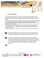
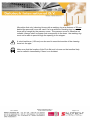
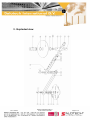
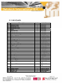
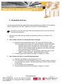
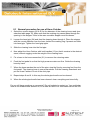
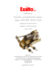
HOSE CATCHER VE.70000
USER MANUAL
Contents
1.
Use and Safety........................................................................................... 3
2.
Safety directions:........................................................................................ 5
3.
Exploded view ............................................................................................ 6
4.
List of parts................................................................................................. 7
5.
Assembly and use ...................................................................................... 9
5.1
General procedure for use of Hose Catcher ..................................... 11
Notes .................................................................. Error! Bookmark not defined.
Rev. 05-2007
Salotech International B.V. ©
Hose Catcher VE.70000
Page 2 of 11
1. Use and Safety
The Hose Catcher (Deflector) is a specially constructed adjustable auxiliary tool for
cleaning pipe bundles by means of a hose with a cleaning nozzle fixed to the front. All
the pipes in the bundle can be reached because of the construction with two hinged
points.
The advantage of the modular construction of the hose catcher is that an adaptor can be
fixed to a foot pedal so that a vertical heat exchanger can be cleaned. Besides this the
hose catcher can be used for one single pipe after removal of the hinged arm.
The Hose Catcher can be fixed to a pipe or heat exchanger in various ways. This will be
explained further in Chapter 5.
Cleaning hoses of different diameters can be used due to the various diameters of the
interchangeable stoppers. The hose catcher can be adjusted by the hand grips for
hoses of various weights, so that the strength necessary to adjust the Hose Catcher
remains the same.
A round (Lexan) plate has been fixed on to protect the operator from backsplash water.
Working with high pressure is not without risk. You must read and follow the
instructions explained in this user manual accurately to work safely. Always
follow the prescribed (safety) procedures before starting high pressure work.
We wish to point out that our products may only be used if the operating
personnel are wearing the correct personal safety equipment. Furthermore it is
strictly recommended that the operator is familiar with the directions laid down
by the Stichting Industriële Reiniging (SIR) [Industrial Cleaning Foundation] and
the Labour Inspectorate, and is also in possession of a certificate ‘High
Pressure Operator’ and/or has sufficient experience with high pressure
apparatus.
Rev. 05-2007
Salotech International B.V. ©
Hose Catcher VE.70000
Page 3 of 11
We advise that only (cleaning) hoses with a marking ring at a distance of 50 mm
behind the pressure cover are used. If a hose without a marking ring is used the
hose will be caught by the pressure cover. This pressure cover is therefore not
suitable. Always select a stopper that corresponds to the hose: the marking ring
must not be able to pass through the opening in the stopper.
A short lead lance (150 mm) can be used to ease the insertion of the cleaning
hose into the pipe.
Make sure that the location of the First Aid post is known so that medical help
can be called in immediately if there is an accident.
Rev. 05-2007
Salotech International B.V. ©
Hose Catcher VE.70000
Page 4 of 11
2. Safety directions:
•
Make sure that the workplace is clean and always fence off an area of at least 6
meters around the spaying area, with tape and warning signs for example.
•
All personnel in the direct vicinity of the workplace must wear the prescribed
protective equipment (earplugs, full face mask, protective boots, protective
gloves, etc).
•
Check whether there is any external damage and if all control functions are
working properly before use. Make sure all the connections are tightly screwed
up and free of leaks. Use well fitting tools for this.
•
Check that the cleaning nozzle is not blocked; clean if necessary or replace.
•
Rinse the hose through before fixing the cleaning nozzle.
•
Always fix the splashboard on the hinged arm.
•
At the start of work increase the pump gently from the stationary to the working
pressure checking, at the same time, whether the connections are still free of
leaks.
•
Never exceed the maximum permitted working pressure.
•
The person operating the cleaning hoses also operates the (dump-style) foot
pedal!
Rev. 05-2007
Salotech International B.V. ©
Hose Catcher VE.70000
Page 5 of 11
3. Exploded view
Rev. 05-2007
Salotech International B.V. ©
Hose Catcher VE.70000
Page 6 of 11
4. List of parts
No.
1
2
3
4
5
6
7
8
9
10
11
12
13
14
15
16
17
18
19
20
21
22
23
24
25
26A
26B
Description
Assembly plate
Hinged arm left
Hinged arm right
Cover
Hinge pin left
Hinge pin right
Axial slide bearing
Cupped spring washer
Washer M16
Handle
Locking pin + clip
Bolt M10 - 50
Washer M10
Locking nut M10
Wing screw M6- 15
Bolt M6 – 50
Washer M6
Locking nut M6
Adapter
Guide bush
Hose connection
Pipe nipple
Protection plate
Hand grip
Retaining ring
Stopper 8.5mm
Stopper 10.5mm
Number
1
1
1
1
1
1
6
6
2
2
1
1
2
1
1
1
2
1
1
1
1
1
1
1
2
1
1
26C Stopper 12.5mm
1
26D
26E
27
28
1
1
1
2
Stopper 14mm
Stopper 28mm
Bolt M8 - 45
Washer M8
Rev. 05-2007
Salotech International B.V. ©
Hose Catcher VE.70000
Art. No.
SL.07-011
SL.07-021
SL.07-031
SL.07-032
SL.07-042
SL.07-043
SL.07-051
SL.07-080
DIN 125 –M16
NLM06440-216
SL.07-090
DIN 933.M10x50
DIN125.M10
DIN985.M10
DIN316.M6x15
DIN316.M06x50
DIN125.M6
DIN985.M06
SL.07-062
SL.07-011-2
FW.6670162
NDX-S23-1 1/4”
SL.07.062
SL.07-061
A-050
RV8-28-108-8.5
RV8-28-10810.5
RV8-28-10812.5
RV8-28-108-14
RV8-28-108-28
DIN933.M8x45
DIN125.M8
Page 7 of 11
29 Nut M8
Rev. 05-2007
1
Salotech International B.V. ©
Hose Catcher VE.70000
DIN934.M8.A2
Page 8 of 11
5. Assembly and use
It is recommended that work with high pressure apparatus is carried out in accordance
with the regulations of the SIR. These can be found in the SIR handbook.
We want to point out once again that only trained personnel may work with the
high pressure apparatus.
1. Determine the best cleaning method and assembly option on the basis of the
situation.
2. Use of hose catcher for a horizontal heat exchanger
a. Determine the best assembly option. The use of the assembly plate
directly up against the flange of the heat exchanger is always preferable.
i. Assembly plate directly up against the heat exchanger. Fix the
assembly plate directly up against the heat exchanger. Make sure
that the correct diameter bolts and washers are used so that they
cannot pass through the bolt holes.
ii. Assembly with clamps. Fix the assembly plate and clamp on the
edge of a heat exchanger. Tighten both bolts to 30Nm.
b. Follow the general procedure described in Chapter 5.1 further.
3. Use of hose catcher for a vertical heat exchanger
a. Dismantle the adapter by removing bolt (12-14).
b. Fix the attachment on the foot pedal, determine on which side you want to
work with the hose catcher. The attachment can be fixed to the foot pedal
on both sides.
c. Fix the adapter on the attachment.
d. Follow the general procedure described in Chapter 5.1 further.
Rev. 05-2007
Salotech International B.V. ©
Hose Catcher VE.70000
Page 9 of 11
4. Use of hose catcher for a pipe.
a. Dismantle the hinge arm by removing locking pin 11. Fixing the locking pin
in the shaft is recommended to prevent the loss of the cupped spring
washer and the axial slide bearings.
b. Fix the assembly plate to the pipe, with clamps if necessary.
i. Assembly plate directly up against the heat exchanger. Fix the
assembly plate directly up against the heat exchanger. Make sure
that the correct diameter bolts and washers are used so that they
cannot pass through the bolt holes.
ii. Assembly with clamps. Fix the assembly plate and clamp on the
edge of a heat exchanger. Tighten both bolts to 30Nm.
Selection table Stopper:
Internal diameter of stopper Hose to be used
8.5mm
4/2
10.5mm
5/2
12.5mm
6/2
14mm
8/2
28mm
1/2” – NW 13
Rev. 05-2007
Salotech International B.V. ©
Hose Catcher VE.70000
Page 10 of 11
5.1 General procedure for use of Hose Catcher
1. Select the correct stopper (26 A-E) for the diameter of the cleaning hose used (see
selection table page 10). Make sure that the marking ring cannot pass through the
opening in the stopper. If this is the case a smaller stopper must be chosen.
2. Loosen the hand grip (24) and feed the cleaning hose through it. Place the stopper
with the correct diameter over the hose, behind the marking ring if present and slide
into hand grip. Tighten the hand grip again.
3. Slide the cleaning hose into the first pipe.
4. Now adjust the Hose Catcher with both handles (10) so that it remains in the desired
stand, without sagging under the weight of the cleaning hose.
5. Fix a hose to the hose connection (21) to remove the returning water.
6. Push the foot pedal in so that the high pressure water can flow. Guide the cleaning
hose by hand.
7. When the hose reaches the end of the pipe: stop the flow by removing foot from the
foot pedal. The cleaning hose is now pressureless. Pull the cleaning hose back and
put the Hose Catcher in front of the next pipe.
8. Repeat steps 8 and 9. In this way the whole pipe bundle can be cleaned.
9. When the whole pipe bundle has been cleaned: clean everything and store tidily.
Do you still have questions or comments? Do not hesitate to contact us. You could also
look at our website www.salotech.nl, or at www.sir-safe.nl for information about the SIR.
Rev. 05-2007
Salotech International B.V. ©
Hose Catcher VE.70000
Page 11 of 11