1
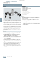
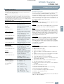
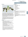
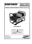
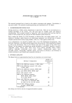
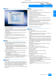
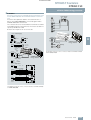
© Siemens AG 2009
SITRANS F flowmeters
SITRANS F US
SITRANS FUE950 energy calculator
■ Schematics
Electrical connection for SITRANS FUS380/FUE950
Electrical connection for SITRANS FM electromagnetic flowmeters MAG 5000/6000 and SITRANS FUE950 in combination
2 resistors are required to obtain a correct transmission of
pulses, when MAG 5000/6000 is connected together with a
SITRANS FUE950 as a heat meter.
The 2 resistors are to be mounted between terminals 57 and 58
in the MAG terminal socket. Moreover, the resistors used are respectively 10 kΩ and 1.5 kΩ.
Resistors are not part of our accessories list.
Flow direction
Up
Down
1A
1B
2A
2B
Power supply
Transmitter
N
N
L
L
PE
PE
PE
66
67
PE
L1
N
Outputs
31
+
32
-
4
56
57
+
11 ... 30 V DC
11 ... 24 V AC
-
115 ... 230 V AC
Current output
(Powered from transmitter)
SITRANS FUE 950
Energy calculator
87... 265 V AC
Battery
0/4 ... 20 mA
Load ≤ 800 Ω
Pulse output
Menu setup:
Negativ:
1
5
Active output
(Powered from transmitter)
6
2
3 7
8 4
The diagram shows the correct connection between SITRANS FUE950
and FUS380/FUE380.
10
Flow Se 11 9
nsor
56
10 kΩ
57
58
1.5 kΩ
6,75$16)8(
Energy calculator
Relay output
44
No
45
Nc
46
Common
Relay
24 V DC/1 A
42 V AC/2A
Digital input
77
78
11 ... 30 V DC
Input
Sensor
Sensor connection
81
Electrode cable
82
81
82
0
0
83
83
84
84
Coil cable
85
85
86
86
Shield
The diagram shows the correct connection between SITRANS FUE950
and MAG 5000/6000.
Siemens FI 01 · 2010
4/249
© Siemens AG 2009
SITRANS F flowmeters
SITRANS F US
SITRANS FUS880 (retrofit kit)
■ Overview
■ Application
•
•
•
•
•
•
•
•
•
Irrigation systems
Irrigation distribution systems
Pumping stations
Canal laterals
On-farm outlets
Water well production
Drip and sprinkler irrigation
Center pivot systems
Potable water
■ Design
4
The SITRANS FUS880 is a battery-powered irrigation flowmeter,
designed for pipes measuring from DN 200 up to DN 1200
(8" up to 48") in diameter. The SITRANS FUS880 gives you the
ability to install the flowmeter underground retrofitting onto existing pipelines. This ultrasonic transient time irrigation flowmeter is
used for full pipe flow measurements. Pipe material may be PVC
or concrete and pipe construction may be single wall or double
wall, smooth or corrugated.
The flowmeter produces a signal proportional to the velocity of
the flow (flow rate) as the liquid flows past the ultrasonic sensors.
SITRANS FUS880 has transducers in the flow (in-line) which assures superior aides in accuracy and superior performance
when compared to doppler or many other types of flow measurement systems.
■ Benefits
• Cost-effective solution - contains all the necessary components for retrofitting onto existing pipe
• Battery-operated - Maintenance-free up to 6 years
• SITRANS FUS880 is easy to install in pipeline sizes from
DN 200 up to DN 1200 (8" up to 48") in diameter
• The transmitter display shows both accumulated volume and
instantaneous flow rate
• The flowmeter provides a digital signal that can be sent directly to a PLC/RTU/DCS
• Solid construction with no moving parts for a 100% maintenance and obstruction-free flowmeter
• The SITRANS FUS880 transmitter comes within an IP67 enclosure
• Sensor can easily be buried and withstand constant flooding
• Automatic calculation of the calibration factor when pipe
geometry data are entered in the signal transmitter
• Pipe material may be polyvinylchloride (PVC) or concrete
• Pipe construction may be single wall or double wall, smooth or
corrugated
4/250
Siemens FI 01 · 2010
The SITRANS FUS880 set contains all necessary parts to build
up an ultrasonic flowmeter on existing pipes depending on
choices at ordering:
• Templates to wrap around pipes for alignment of sensors
• Transducer threading tool
• Thread adapters
• Transducer alignment tools
• Mounting plugs or saddles as well as FUS880 transmitter dependant upon the specifics at time of ordering and required
mounting hardware
• Cables
© Siemens AG 2009
SITRANS F flowmeters
SITRANS F US
SITRANS FUS880 (retrofit kit)
■ Technical specifications
■ More information
Accuracy
Typical ≤ ± 2.0%, dependant upon the accuracy of measurements of
tube diameter and during installation
Note:
Flow system measurement performance depends on the accuracy of
the measurements taken at time of installation. This means that inaccurate measurements of angles, distance between transducers, wall thickness and pipe diameter have a direct effect on the accuracy as these
values measured are entered into the memory of the FUS880 transmitter
and used in part of the calculation of flow rate.
The space requirements around the pipe for retrofitting an ultrasonic flowmeter type SITRANS FUS880 are given below:
It is important to prepare excavation site for a safe and efficient
installation. An underground pipe needs to be exposed so that
there is a minimum of 1.52 m (5 ft) or more of working space on
either side of the pipe. The length of the trench should exceed
the template length by 1.83 m (6 ft) or more.
Pipe support:
Requirements for pipes
Size
Installation requirement
DN 200 ... DN 1200 (8" ... 48" )
Transmitter Enclosure
Ensure that an unearthed pipe has sufficient support beneath it
to prevent deformation or breakage.
Cave-in:
Rating
IP67 rated enclosure
Material
Fibre glass reinforced polyamide
Terminal box
PA 6.6, 100 °C (212 °F)
Transducer element
AISI 316 Stainless Steel 200 °C
(392 °F)
2000 Corrugated PVC
Transducer holder: Polyvinyl chloride
Mounting saddle: Polyvinyl chloride
• Line pressure max.
Pressure rating per spec. ASTM
D-1784 (5.5 bar (80 psi))
Follow all safety recommendations listed by the epoxy manufacturer. Use proper protection equipment, such as gloves, safety
glasses, clothing, etc. Read the labels on the epoxy cans before
mixing. Note all safety related statements and temperature recommendations in particular. For additional information, see the
epoxy manufacturer's internet site.
• Liquid temperature max.
Temperature rating per spec. ASTM
D-1784 (60 °C (140 °F))
Pipe template:
Pro21 Corrugated PVC
Transducer holder: Polyvinyl chloride
Mounting saddle: Polyvinyl chloride
• Line pressure max.
Pressure rating per spec. ASTM
D-1784 (5.5 bar (80 psi))
• Liquid temperature max.
Temperature rating per spec. ASTM
D-1784 (60 °C (140 °F))
Templates are printed on a durable material, such as Mylar, and
are resistant to normal contaminants. Do not expose the template to excessive moisture or excessive periods of sunlight,
heat and cold temperatures. Always roll and store the template
in its' shipping tube. Do not stretch or fold as this could permanently damage the template.
PVC Solid PIP 80
Transducer holder: Polyvinyl chloride
Mounting saddle: Polyvinyl chloride
• Line pressure max.
Pressure rating per spec. ASTM
D-1784 (5.5 bar (80 psi))
• Liquid temperature max.
Temperature rating per spec. ASTM
D-1784 (60 °C (140 °F))
Concrete
Transducer holder: Polyvinyl chloride
Mounting saddle: Polyvinyl chloride
• Line pressure max.
Pressure rating per spec. ASTM
D-1784 (5.5 bar (80 psi))
• Liquid temperature max.
Temperature rating per spec. ASTM
D-1784 (60 °C (140 °F))
Structural Epoxy joint meets spec.
ASTM D1002 (118 bar or 1710 psi)
Pipe wall thickness
A2000 Corrugated PVC
25 ... 50 mm (1" ... 2")
Pro21 Corrugated PVC
25 ... 50 mm (1" ... 2")
PVC Solid PIP 80
Less than 25 mm (1")
Concrete
• 51 ... 57 mm (2“ ... 2.25“)
• 57 ... 64 mm (2.25“ ... 2.5“)
• 70 ... 76 mm (2.75“ ... 3“)
• 76 ... 83 mm (3“ ... 3.25“)
• 89 ... 95 mm (3.5“ ... 3.75“)
• 95 ... 100 mm (3.75“ ... 4“)
• 108 ... 114 mm (4.25“ ... 4.50“)
Always brace trench walls. Follow all applicable (e.g. municipal,
company, customer, site, union) construction guidelines.
Epoxy:
Installation overview:
Installation steps
Installation of the SITRANS FUS880 is accomplished with the following steps.
1. Expose and clean the pipe.
2. Mark a centerline on the pipe.
3. Place the template on the pipe and tape it securely to the
pipe.
4. Mark the locations of the sensor mounting holes on the pipe.
5. Drill the sensor mounting holes in the pipe.
6. Clean and de-burr the sensor mounting area.
7. Measure up the pipe circumference C, the wall thickness WT
and calculate OD and ID.
8. Epoxy and screw the saddle sensor holder to the pipe.
9. Assemble and install the sensors-holders.
10. Measure up the actual sensor-location to see if re-calibration
is needed.
11. Assemble and install the sensors.
12. Install sensor wiring and conduit.
13. Install the transmitter and connect the sensor wiring.
14. Check the transmitter configuration.
15. Test the installation thoroughly and run a flow test.
16. Fill in the "Site Acceptance Form".
17. Cover the pipe.
For detailed instruction in installation please refer to User Manual
Order no.: FDK:521HAP0553.
Siemens FI 01 · 2010
4/251
4
© Siemens AG 2009
SITRANS F flowmeters
SITRANS F US
SITRANS FUS880 (retrofit kit)
Selection and Ordering data
Order No.
Selection and Ordering data
SITRANS F US
Ultrasonic flowmeters
SITRANS FUS880 PVC (Solid) (PIP80)
SONOKIT
Battery-powered
7 ME 3 4 4 0 -
SITRANS F US
Ultrasonic flowmeters
SITRANS FUS880 A2000 Corrugated PVC
SONOKIT 1-track
Battery-powered
7 77 7 7 - 7 7 7 7
Pipe diameter
4
Order No.
7 ME 3 4 4 0 7 77 7 7 - 7 7 7 7
Pipe diameter
DN 200 (8")
DN 250 (10")
DN 300 (12")
DN 380 (15")
2F
2K
2P
2M
DN 450 (18")
DN 530 (21")
DN 600 (24")
DN 680 (27")
3F
3M
3T
4D
3T
4K
5B
C
Pipe material
B
PVC Corrugated A2000
3
Track configuration
1
1-track
Track configuration
1-track
2-track X-configuration
DN 600 (24")
DN 750 (30")
DN 900 (36")
25 ... 50 mm (1“ ... 2“)
Pipe material
PVC (Solid) (PIP80)
2V
3F
3M
Wall thickness
Wall thickness
Less than 25 mm (1“)
DN 380 (15")
DN 450 (18")
DN 530 (21")
1
Region version
1
3
2
EU, US
Transmitter
Region version
D
SITRANS FUS080, IP67, Battery-powered
2
EU, US
Template
Transmitters
A
Standard
D
SITRANS FUS080, IP67, Battery-powered
Cable length
Template
Cable length
Selection and Ordering data
4
20 m (65.6 ft) with gland
Selection and Ordering data
Order code
Further designs
Please add „-Z“ to Order No. and specify Order code(s).
Add on units of measure
4
20 m (65.6 ft) with gland
A
Standard
Order code
Further designs
Please add „-Z“ to Order No. and specify Order code(s).
Add on units of measure
Flow unit GPM
Flow unit CFS
Flow unit m3/h
L01
L02
L03
Flow unit GPM
Flow unit CFS
Flow unit m3/h
L01
L02
L03
Flow unit MGD
Volume unit US Gal
Volume unit m3/h
L05
L42
L44
Flow unit MGD
Volume unit US Gal
Volume unit m3/h
L05
L42
L44
Volume unit US Gal x 100
Volume unit US Gal x 1000
Volume unit US Mgal
L46
L49
L48
Volume unit US Gal x 100
Volume unit US Gal x 1000
Volume unit US Mgal
L46
L49
L48
Volume unit AcF (Acre Feet)
Volume unit AcI (Acre Inch)
L43
L51
Volume unit AcF (Acre Feet)
Volume unit AcI (Acre Inch)
L43
L51
4/252
Siemens FI 01 · 2010
© Siemens AG 2009
SITRANS F flowmeters
SITRANS F US
SITRANS FUS880 (retrofit kit)
Selection and Ordering data
Order No.
Selection and Ordering data
Order No.
SITRANS F US Ultrasonic flowmeters
SITRANS FUS880 Pro21 Corrugated PVC
SONOKIT 1-track
Battery-powered
7 ME 3 4 4 0 -
SITRANS F US Ultrasonic flowmeters
SITRANS FUS880 Concrete
SONOKIT 1-track
Battery-powered
7 ME 3 4 4 0 -
7 77 7 7 - 7 7 7 7
Pipe diameter
7 77 7 7 - 7 7 7 7
Pipe diameter
DN 750 (30")
DN 840 (33")
DN 900 (36")
4K
4P
5B
DN 300 (12")
DN 380 (15")
DN 450 (18")
2P
2V
3F
DN 1050 (42")
DN 1200 (48")
5M
5T
DN 530 (21")
DN 600 (24")
DN 680 (27")
3M
3T
4D
DN 750 (30")
DN 900 (36")
DN 1050 (42")
4K
5B
5M
Wall thickness
25 ... 50 mm (1“ ... 2“)
C
Pipe material
PVC Pro21 Corrugated
2
1-track
1
Region version
2
EU, US
Transmitter
D
SITRANS FUS080, IP67, battery-powered
Template
51 ... 57 mm (2“ ... 2.25“)
57 ... 64 mm (2.25“ ... 2.5“)
70 ... 76 mm (2.75“ ... 3“)
76 ... 83 mm (3“ ... 3.25“)
D
E
F
G
89 ... 95 mm (3.5“ ... 3.75“)
95 ... 100 mm (3.75“ ... 4“)
108 ... 114 mm (4.25“ ... 4.5“)
H
J
K
Pipe material
A
Standard
4
Concrete
Cable length
Track configuration
4
20 m (65.6 ft) with gland
Selection and Ordering data
4
Wall thickness
Track configuration
Order code
1
1-track
Region version
2
EU, US
Further designs
Please add „-Z“ to Order No. and specify Order code(s).
Transmitter
Add on units of measure
SITRANS FUS080, IP67, battery-powered
Flow unit GPM
Flow unit CFS
Flow unit m3/h
L01
L02
L03
Template
Flow unit MGD
Volume unit US Gal
Volume unit m3/h
L05
L42
L44
20 m (65.6 ft) with gland
Volume unit US Gal x 100
Volume unit US Gal x 1000
Volume unit US Mgal
L46
L49
L48
Further designs
Volume unit AcF (Acre Feet)
Volume unit AcI (Acre Inch)
L43
L51
D
A
Standard
Cable length
4
Order code
Selection and Ordering data
Please add „-Z“ to Order No. and specify Order code(s).
Add on units of measure
Flow unit GPM
Flow unit CFS
Flow unit m3/h
L01
L02
L03
Flow unit MGD
Volume unit US Gal
Volume unit m3/h
L05
L42
L44
Volume unit US Gal x 100
Volume unit US Gal x 1000
Volume unit US Mgal
L46
L49
L48
Volume unit AcF (Acre Feet)
Volume unit AcI (Acre Inch)
L43
L51
Siemens FI 01 · 2010
4/253
© Siemens AG 2009
SITRANS F flowmeters
SITRANS F US
SITRANS FUS880 (retrofit kit)
Selection and Ordering data
Accessories and Spare parts
Order No.
SITRANS F US Ultrasonic flowmeters
FUS880 transmitter
includes 2 transducers and 20 m (65.6 ft)
of cable
7ME3440-0AA01-2DA4
FUS880 Installation pipe template
4
Template, PVC PIP 80
DN 250 (10“)
DN 300 (12“)
DN 380 (15“)
DN 450 (18“)
TGX:16347-80
TGX:16347-81
TGX:16347-82
TGX:16347-83
DN 530 (21“)
DN 600 (24“)
DN 680 (27“)
TGX:16347-84
TGX:16347-85
TGX:16347-86
Template, Concrete
DN 300 (12“)
DN 380 (15“)
DN 400 (16“)
DN 450 (18“)
TGX:16347-90
TGX:16347-91
TGX:16347-89
TGX:16347-92
DN 530 (21“)
DN 600 (24“)
DN 680 (27“)
DN 750 (30“)
TGX:16347-93
TGX:16347-94
TGX:16347-95
TGX:16347-96
Selection and Ordering data
Holder - Plug
51 ... 57 mm (2“ ... 2.25“) Cement sensor
holder, PVC
57 ... 64 mm (2.25“ ... 2.5“) Cement sensor
holder, PVC
70 ... 76 mm (2.75“ ... 3“) Cement sensor
holder, PVC
76 ... 83 mm (3“ ... 3.25“) Cement sensor
holder, PVC
89 ... 95 mm (3.5“ ... 3.75“) Cement sensor
holder, PVC
102 ... 108 (4" ... 4.25") Cement sensor
holder, PVC
108 ... 114 mm (4.25“ ... 4.5“) Cement
sensor holder, PVC
A2000 - DN 900 (36“) ID
PRO-21 - DN 1050 (42“) ID
TGX:16347-121
TGX:16347-122
TGX:16347-123
TGX:16347-124
TGX:16347-125
TGX:16347-127
TGX:16347-134
TGX:16347-135
TGX:16347-235
TGX:16347-236
TGX:16347-237
TGX:16347-238
Adhesive
1 lb epoxy
A6X30004048
Adapter
TGX:16347-97
TGX:16347-98
Template, pipe DN 900 (36“) PVC, A2000
corrugated
TGX:16347-100
Tools
Template, pipe DN 1050 (42“) Pro21 corrugated
TGX:16347-101
Sensor Wrench
Alignment Tool
Conduit adapter
A6X30003981
TGX:16347-111
TGX:16347-137
Documentation
Manual
FUS880 Installation spare kit
FDK:521HAP0553
Converter
Concrete kit, Sensor mounting
51 ... 57 mm (2“ ... 2.25“)
57 ... 64 mm (2.25“ ... 2.5“)
70 ... 76 mm (2.75“ ... 3“)
76 ... 83 mm (3“ ... 3.25“)
TGX:16347-213K
TGX:16347-214K
TGX:16347-215K
TGX:16347-216K
89 ... 95 mm (3.5“ ... 3.75“)
95 ... 100 mm (3.75“ ... 4“)
108 ... 114 mm (4.25“ ... 4.5“)
TGX:16347-217K
TGX:16347-218K
TGX:16347-212K
PVC kit, Sensor Mounting
DN 300 (12“)
DN 380 (15“)
DN 450 (18“)
DN 530 (21“)
TGX:16347-219K
TGX:16347-220K
TGX:16347-221K
TGX:16347-222K
DN 600 (24“)
DN 680 (27“)
TGX:16347-223K
TGX:16347-224K
Corrugated PVC kit, DN 900 (36“) A2000
TGX:16347-225K
Corrugated PVC kit, DN 1050 (42“’) Pro21
TGX:16347-226K
FUS880 spares
Holder - Saddle
DN 250 (10“) PIP 80 PVC Saddle
DN 300 (12“) PIP 80 PVC Saddle
TGX:16347-165
TGX:16347-166
DN 380 (15“) PIP 80 PVC Saddle
DN 450 (18“) PIP 80 PVC Saddle
DN 530 (21“) PIP 80 PVC Saddle
TGX:16347-168
TGX:16347-170
TGX:16347-174
DN 600 (24“) PIP 80 PVC Saddle
DN 680 (27“) PIP 80 PVC Saddle
TGX:16347-175
TGX:16347-177
Siemens FI 01 · 2010
TGX:16347-120
Straps -Kits
Strap kit for -134 & -135 plugs
Strap kit for -120, -121, -122, -123 plugs
Strap kit for -124 & -125 plugs
Strap kit for -127 plug
DN 900 (36“)
DN 1050 (42“)
4/254
Order No.
FUS880 converter kit for 2 track SYS
7ME3440-0AA03-2DA4
Note:
Installation spares kit include:
Concrete kit:
2 transducer mounting plugs, 2 straps, mounting hardware, epoxy,
conduit adapter, installation guide
PVC kit:
2 transducer mounting saddles, mounting hardware, epoxy, conduit
adapter, installation guide