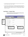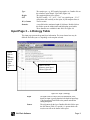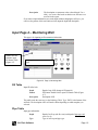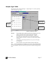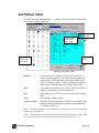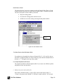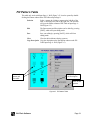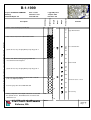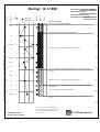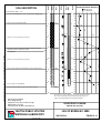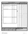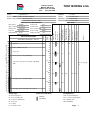
1
SuperLog User’s Manual Version 4 and up Borehole Log and Test Pit Log Drawing Program for Geotechnical, Geological, Environmental, Mining and Oil Industries 9.1.08 CivilTech Software All the information, including technical and engineering data, processes, and results, presented in this program have been prepared according to recognized contracting and/or engineering principles, and are for general information only. If anyone uses this program for any specific application without an independent competent professional examination and verification of its accuracy, suitability, and applicability by a licensed professional engineer, he/she does so at his/her own risk and assumes any and all liability resulting from such use. In no event shall CivilTech be held liable for any damages including lost profits, lost savings, or other incidental or consequential damages resulting from the use of or inability to use the information contained within. Information in this document is subject to change without notice and does not represent a commitment on the part of CivilTech Corporation. This program is furnished under a license agreement, and the program may be used only in accordance with the terms of the agreement. The program may be copied for backup purposes only. Program may be updated from time to time without updating the document. The program may be different from what presented in this document. The program or user’s guide shall not be reproduced, stored in a retrieval system, or transmitted in any form or by any means, electronic, mechanical, photocopying, recording, or otherwise, without prior written consent from CivilTech Corporation. Copyright 2007 CivilTech Corporation. All rights reserved. Simultaneously published in the U.S. and Canada. Printed and bound in the United States of America. Published by CivilTech Software 10800 NE 8th Street Suite 820 Bellevue, WA 98004 U.S.A. Sale E-mail: [email protected] Tech. E-mail: [email protected] Web Site: www.civiltechsoftware.com CivilTech Software SUPERLOG FOR WINDOWS USER’S MANUAL Table of Contents CHAPTER 1 INTRODUCTION ...................................................................................................1 ABOUT THE P ROGRAM....................................................................................................................1 FEATURES .....................................................................................................................................1 ABOUT THE COMPANY ...................................................................................................................1 CHAPTER 2 INSTALLATION AND REGISTRATION..............................................................2 INSTALLATION ...............................................................................................................................2 REGISTRATION...............................................................................................................................2 CHANGING FIRM NAME OR USER DATA...........................................................................................3 TERMINOLOGY ..............................................................................................................................3 FILES AND FILE LOCATIONS............................................................................................................4 FAQS............................................................................................................................................4 CHAPTER 3 DATA INPUT.........................................................................................................5 COVER P AGE .................................................................................................................................5 INPUT P AGE 1 – GENERAL ..............................................................................................................6 Project Information ....................................................................................................................6 Total Log List.............................................................................................................................6 Current Log Data .......................................................................................................................7 Current Log Information.............................................................................................................7 Memo of Current Log .................................................................................................................7 INPUT P AGE 2 – SAMPLE TABLE......................................................................................................8 INPUT P AGE 3 – LITHOLOGY TABLE ................................................................................................9 INPUT P AGE 4 – MONITORING WELL ............................................................................................. 10 Fill Table .................................................................................................................................10 Pipe Table ...............................................................................................................................10 TIPS FOR DATA INPUT .................................................................................................................. 11 P REFERENCES .............................................................................................................................. 12 CHAPTER 4 MENUS, TOOLBARS, AND TABLES..................................................................13 THE MAIN MENU ......................................................................................................................... 13 File .........................................................................................................................................13 Log..........................................................................................................................................13 Edit .........................................................................................................................................14 Tools.......................................................................................................................................14 Table .......................................................................................................................................14 Output.....................................................................................................................................14 Help ........................................................................................................................................14 THE TOOLBAR ............................................................................................................................. 15 AUTO SAMPLE P ANEL .................................................................................................................. 16 SAMPLE TYPE TABLE ................................................................................................................... 17 SOIL P ATTERN TABLE .................................................................................................................. 18 DUAL P ATTERNS PANEL ............................................................................................................... 19 FILL P ATTERN TABLE................................................................................................................... 21 ABBREVIATION AND BOILER TABLES (SPEED TABLES) ................................................................... 22 SPELL CHECK ........................................................................... ERROR! B OOKMARK NOT DEFINED . CHAPTER 5 VIEW AND PRINT REPORT...............................................................................23 VIEW AND P RINT UTILITY ............................................................................................................ 24 CivilTech Software Table of Contents Page 1 of 2 CHAPTER 6 TEMPLATE DESIGN ...........................................................................................25 THE MAIN MENU ......................................................................................................................... 25 THE TOOLBAR ............................................................................................................................. 25 DESIGN P AGE 1............................................................................................................................ 26 P ROJECT TABLE - 1...................................................................................................................... 26 Log Table - 2............................................................................................................................27 Main Table - 3 .........................................................................................................................27 Graphical Symbols for Test Data...............................................................................................35 DESIGN P AGE 2............................................................................................................................ 36 Text Table 4 .............................................................................................................................36 Line Table 5.............................................................................................................................37 DESIGN P AGE 3............................................................................................................................ 37 Rectangle Table 6.....................................................................................................................38 Page Layout Items....................................................................................................................38 Company Title and Logo...........................................................................................................38 Default Log End Text................................................................................................................39 Graphical Range ......................................................................................................................39 P REVIEW SCREEN ......................................................................................................................... 39 APPENDIX A PRE-DESIGNED TEMPLATES AND FILES.....................................................40 APPENDIX B KEY PAGES AND SYMBOL FILES...................................................................40 CivilTech Software Table of Contents Page 2 of 2 CHAPTER 1 INTRODUCTION Introdu About the Program SuperLog generates boring log and test pit reports for field drilling and geotechnical investigations. It saves countless hours spent preparing and retrieving boring logs. This benefit can begin immediately since the program is extremely easy to learn and use. With a laptop computer you can even enter in the data during the actual drilling. Advanced capabilities include rapid input, e.g., typing "f to m sa" will pop out "fine to medium sand." The user can personalize the abbreviation list. Automatic depth generation, boilerplate, and spell check make the input fast and enjoyable. The program offers many templates for outputting log information. Users can modify any of the templates included with the program. The program license is for one user on a single computer only. Features • • • • • • • • • • Supports multiple borings and multiple pages Uses graphical symbols and patterns Handles English and metric units Provides a graphical interface and instant preview Logs piezometers/monitoring wells Shows dual patterns and USCS symbols Incorporates boilerplate to reduce repetitive typing Produces high quality output with laser fonts Has unlimited user-editable templates Spell checks About the Company The software was developed by CivilTech Software, a subsidiary of CivilTech Corporation. CivilTech Software employs engineers with experience in structural, geotechnical, and software engineering. These engineers have many years of experience in design and analysis in these fields as well as in special studies including seismic analysis, soil-structure interaction, and finite element analysis. CivilTech has developed a series of engineering programs that are efficient, easy to learn, engineering oriented, practical, and accurate. CivilTech Software programs include PlanTrack, TimeTrack, DailyReport, WinMarket, Shoring, Heave, Lpres, Epres, Upres, Tunnel, Buried Structures, All-Pile, SuperLog, Pinned Pile, and Lab Testing programs. These programs are widely used in the U.S. and around the world. For more information, visit our Web site at www.civiltech.com. CivilTech Software Page 1 CHAPTER 2 INSTALLATION AND REGISTRATION Installation Setup Insert the setup disk into floppy drive A: or B. In Windows 3.1, go to the [FILE] menu and select [RUN]. In Windows 95, 98, 2000, or NT press <START> and select [RUN]. Type: A: setup or B: setup Press <OK> and follow the directions on the screen. The installation program will automatically create a shortcut icon called “SuperLog” on your Windows desktop and a SuperLog folder. When you first start the program you will be in unregistered mode. To register the software, see the instructions in the Registration Section below. Configuration The software configuration uses your existing Windows settings. However, you can change your configuration later in Windows. (Consult your Windows manual for instructions.) The recommended resolution is higher than 800 x 600. Starting the Program Double click the shortcut icon called “SuperLog” on your Windows desktop or from <START> select [Programs/Superlog]. Quit Program Press [Exit] from the [File] menu. Registration You will need to register your copy of this software to use its full capabilities. When you first start the program, the Registration Panel will appear (Figure 2-1.) If you do not register at this time you can always open this window which is located under the [HELP] menu as the option [REGISTER]. After your registration has been accepted, this window will disappear. The program will find the CPU ID number of Figure 2-1 Registration Panel your computer and indicate it at the top of the registration panel. You may provide this number to CivilTech by telephone, email, or fax. In return, you will be given a registration code to enter into the panel, along with your user name and company name. Click Register to close the program. Re-open it and you will have full program capabilities. You will need to have one license for each computer running the program. Additional licenses may be obtained at discounted rates. If further information is desired, please contact CivilTech. CivilTech Software Page 2 Changing Firm Name or User Data You can change the Firm Name and User Data that the program has been registered to. Please bear in mind that if the registered user or firm changes, you should contact us to re-register it under the name. This will allow you to still be eligible for upgrades and support. To change the registered Firm Name and User Data, click on <Help> on the upper menu bar and then <Register> to open up the registration window. Enter in the new name (user or firm) with the current registration code. (If your old code does not work any more, contact us for a new one). You will need to quit and restart the program. For instructions on changing the logo and company name in the log reports, please refer to Chapter 6. Terminology Log A log representing a boring, test pit, or well. Log File A file containing several logs. The log file has the extension “.log”. Template Also called a form. This is the format associated with the log. The program can handle an unlimited number of templates and provides a template design utility. A log file can only have one template. You can change the template after the log file has been created. Template File A file containing a template. A template file has the extension “.fom”. Report A printed graphical report of the logs. One report may have multiple pages. Current Log File The log file you are currently working on. Current Log A log file may have many logs. The one you are currently editing is called the current log. Current Template The template used by the current log file (in data input mode). Default Template You can save the template you use most often as the default template. When you create a new log, the program will use the default template on the new log file (and if you change your mind, you can always change the template later.) See Chapter 6 for instructions. CivilTech Software Page 3 Files and File Locations The SuperLog default folder is “C:/Superlog”. You can also install the program in the folder of your choice during installation, such as “D:/engineer/SuperLog”. This folder contains major executive files, a dictionary, and template files. The template files have the extension “.fom”. Typical file names are “F1. fom”, “Default.fom”, etc. The template files are located in the same folder as the other program files. The log files are the files containing the data for the boring logs and the project. They have the extension “.log”. In the initial installation, the sample log files are installed in a sub folder named “project”. The typical location is “C:/Superlog/project/”. The user may save the log files into a different folder such as “/project2/”, “/logfile/”, etc. The user can set these folders as a default folder so that when the program is opened, the default folder is the first choice. To set a folder as default, click “File” on the main menu bar and select “Save Path as Default”. There are three EXE programs in the program package: SuperLog.EXE The main program to generate log reports. The design utility is also inside. ViewDemo.EXE A program demonstrating all attached templates. View.EXE A royalty-free viewing utility to view the saved report (see “All Logs Report” in Chapter 5). FAQs Q: Can I change templates after a log is created? A: Yes. Click “Tools” then “Change Template”. However, the new template may not have the same data structures as the previous one. Some adjustments may be necessary. Q: Can I have different templates for each log in the same project? A: Only one template per log file is allowed. You can create two log files for one project, each having its own template. Or you can change the template for a single log, print it, and then change the format back again. Q: Does the program support a graphical format for the test data? A: Yes. In the Template Design area, you can specify whether the test data will be presented graphically. You also need to set the lower limit and upper limit of the test data. For example, SPT or Moisture Contents can be presented with graphics. Q: Does the program support monitoring wells? A: Yes. See the Well section. Q: How do I start a new line in the Description? A: Entering a tilde (~) between two letters moves the next letter to a new line. CivilTech Software Page 4 CHAPTER 3 DATA INPUT The following sections describe how to enter data into the program, page by page. Cover Page The cover page (Figure 3 – 1) can be accessed after launching the program by clicking “File/New” on the toolbar. [Open File] Opens an existing log file. [Create New] Creates a new log file. Total Logs [Template] Enters the number of logs for the new log file. You can always add or duplicate new logs to existing files later. You can either use the default template or change to a different template. Press this button to open a dialog box that allows you to select a pre-designed template file. After selecting a template, press [Create New]. Note: Each template is presented in a template file; the name of the current template file selected is shown beside the [Template] button. Total number of logs Current template file Figure 3-1 Cover Page CivilTech Software Page 5 Input Page 1 – General The first, or “General,” input page is divided into halves. The left half pertains to the project and file information, and the right half contains log information. File name Tip: Typing a period (.) before text will prevent the text from showing in the report. Left half = project information Right half = log information Figure 3-2 Page 1, General Log File: The path and file name of the log file. The file name also shows in the top left corner of the screen. Template: The template associated with the log file. Project Information The Project Information fields contain the general information about the project, which shows on every log report. If a period (.) is present before the title name in the left column, the information in the right column will not be shown on the report. Total Log List This table is a non-editable list of the individual logs in the log file. (It cannot be edited directly, as the information is input from other places.) No. Log number Name Log name Depth Borehole depth in feet or meters CivilTech Software Page 6 Scale Scale index number Page Page starting number of the current log Current Log Data Current log data pertain to the current individual log. Hole Depth The maximum depth of the hole GWT1 Depth of the groundwater table encountered during drilling and encountered date. If this box is blank, a text, “GWT not encountered” is presented in water column. If “–1” is inputted, the text will not presented. GWT2 Second water table measurement, e.g., several days after Drilling and date of measurement. Scale The vertical scale used in the log report Page Number The beginning page number of the log X (sta.) X coordinate or station of the log location Y (off.) Y coordinate or offset of the log location Z (elev.) Elevation of the top of the boring hole Drawing If the template has a drawing, you can open and attach it to the log. Draw Create or edit drawings Current Log Information If a period (.) is inserted before the title name, the text will not be shown in the report. Memo of Current Log The memo field is for reference only and will not show in the report unless the current template has a “Remarks” field for this purpose (see Template 16). Water Table Date The date of ground water measurement can be input and presented in the report. The input is on the Page 1, General Page. If there is no date to input, leave the input box blank. The default setting is showing the date above the water symbol in the report. You can also rotate the date 90 degrees. To set this option, open the Template Design Screen (Tools/Design Template), then in the Design Page 1, Main Table -3, set the <Style> property in <Water> row = 1 as shown in Figure 3. The default setting is 0 Page Number Options There are two options for page numbering. CivilTech Software Page 7 1. The default option has the pages numbered sequentially in each log. If the first log has 3 pages, the number of each page is Page 1, Page 2, and Page3. 2. The other option is to number all the pages in a log with the same page number. If the first log has three pages, each page will be numbered Page 1. The second log has all page numbers Page 2. To set this option, open the Template Design Screen (Tools/Design Template), then in the Design Page 1, Main Table-3, set the <Line/w> property in <Page No.> row = 1 as shown in Figure 3. The default setting is 0 for the option 2. Input Page 2 – Sample Table This page is for inputting sample information. Depending on the template you choose, the items in this example may be different from the template you view. However, the following information is provided on a typical template. Double click this column to open Auto Sample Panel (Figure 43). Double click this column to open Sample Type Table (Figure 4-4). Double click this column to open Speed Tables (Figure 4-8). Figure 3-3 Page 2, Sample Depth CivilTech Software The depth of the sample top. The Auto Sample Panel can be opened by double-clicking on this column. See Figure 4-3. Page 8 Type Height SPT W%, Gamma Remarks The sample type, e.g., SPT sample, bag sample, etc. Double click on this column to open Sample Type Table (Figure 4-4). The sample height in feet or meters The SPT reading. “12”, “6/15”, “3,4,5” are typical inputs. “5-2-3” will split the data vertically on the report, if your template allows it. The test results A text field with a maximum length of 100 letters. Double click on this field to open the Abbreviation and Boilerplate speed tables. These functions are available for this field. See Figure 4-8 Input Page 3 – Lithology Table This input page presents the ground layer information. The items shown here may be different from what you see, depending on the template selected. Double click on this column to open Soil Pattern Table (Figure 45). Double click this column to open Speed Tables (Figure 4-8). Figure 3-4 Page 3, Lithology Depth The depth of the soil layers and soil information. If the depth you input is greater than the hole depth in Input Page 1, the program will add END as the pattern and add the ending description. Pattern The soil pattern for the layer. Double click this field to open the Soil Pattern Table. If a period (.) is present before the text, the text will not be shown in the report. CivilTech Software Page 9 Description The description or comments at the selected depth. Use a tilde (~) to create a line break so that the text will move to a new line in the report. If you want to input information at a certain depth without changing the soil layer, you can leave the pattern of this row blank and only input the depth and description. Input Page 4 – Monitoring Well This page is for inputting well construction information. Double click this column to open Fill Pattern Table (Figure 4-7). Highlight a row, and then select a type Figure 3-5 Page 4, Monitoring Well Fill Table Input fill of the hole: Depth Pattern Description Depth of top of fill (change of fill material). Fill Pattern. Double click to open Fill Pattern Table (Figure 4–7). Description of fill. This table works the same way as the Lithology Table. Type “END” at the bottom of the well hole. The description will or will not be shown depending on which template you selected. Pipe Table Input pipe information: Depth Type CivilTech Software Depth of well cap (the first row) and depth of pipe type end (rows 2 to 4) Type of well cap and pipe type. Page 10 Description Text description of cap and pipe. • The first row is for the well cap. You can select from C1 to C4 based on the Pipe Type Table. • The next 3 rows are for pipe type. You can select from P1 to P8 based on the Pipe Type Table • The pipe span starts from the depth of the previous row to the depth of the current row. Note: Rows 2 to 4 show the pipe type end. It is the end of the pipe type specified in the second column of the same row. Use the Pipe Type Table to select pipe type. • Select a type from C1 to C4 for the well cap. It must be imported in the first row of the Pipe Table. • Select a type from P1 to P8 for the pipe type. It must be imported to the 2nd to 4th rows of the Pipe Table. You can highlight the row in the Pipe Table then click the pipe type from the Pipe Type Table. The selected pipe type goes to the Pipe Table. The row should be highlighted before clicking the pipe type. Tips for Data Input There are two modes of inputting data into a table: Overwrite Mode – When you click on a cell or use the arrow keys to move the cursor to a cell, all the text in the cell will be automatically highlighted. Simply begin typing and all the text will be overwritten. This is a default mode. Press F2 to change to Edit Mode. Edit Mode – By pressing the F2 key or using the Enter key to move the cursor down, the cursor will automatically go to the end of the existing text. Any new typing will follow the existing text. Inputting data into a table cell is easy. The following tips may also help: 1. If the cell is not empty, new typing will overwrite the existing text unless you press F2. Pressing F2 will move the cursor to the end of the existing text. Then the text you type will be added to the end of the existing text. 2. Clicking a cell twice will open a table if the cell is associated with a table. 3. Abbreviation typing is available in the Remark Column (Input Page 2 – Sample), and the Description Column (Input Page 3 – Lithology). For example, if you type “f to m sa” and press the enter key, the text will read “fine to medium sand”. You can create your own abbreviations on the Abbreviation Table. 4. You can add common phrases into the Boilerplate and reuse them later. This is available by double clicking on the Remarks column (Input Page 2 – Sample) and the Description/Text column (Input Page 3 – Lithology). 5. Copy Text – Use the mouse to click the cell you wish to copy. The text in the cell will be highlighted. Then, press the right mouse button and select “copy” from the edit panel. See Figure 3-6. 6. Paste Text – Move the mouse to the desired cell and press the right mouse button again. Select “paste” from the edit panel. CivilTech Software Page 11 Figure 3-6 Use Right Mouse Click to Cut/Copy/Paste Text Figure 3-7 Options Options Panel From the pull-down menu, Tools/Options, the Options panel can be opened. Three items can be changed by users: 1. Method for opening the pop-up reference tables for Symbol, Pattern, and Abbreviation. Choose a mouse operation or the function key. 2. Descriptions on multiple pages. If a log splits into several pages and one soil type also splits into two pages, the descriptions of the soil type will appear on the subsequent page. If you do not want the descriptions to appear on the subsequent page, you can turn the function off. 3. Show vertical text. You can turn off the page border and the vertical text on the left side of the page. It is useful if you want to copy the graphical report to other Windows programs or save it to a metafile. CivilTech Software Page 12 CHAPTER 4 MENUS, TOOLBARS, AND TABLES The Main Menu Each item in the main menu has a pull-down menu. Figure 3-7 Option Panel Figure 4-1 The Log Pull-Down Menu File Contains file-handling operations. New Create a new log file. Open Open an existing log file. Save Save the current log file. Save As Save the current log file as a new name. Save Path as Default Save the path of the current log file as the default path so that you can go to the directory directly when the program opens. Exit Exit the program. Log Contains log-handling operations. Go to first log Move to the first log. Go to last log Move to the last log. Add new blank log Adds a new blank log at the end. Add duplicate log Adds a new log at the end that is the same as the current log. Delete last log Deletes the last log. Only the last log is deletable. CivilTech Software Page 13 Edit Operations for editing text. Copy row Copies the current row. Paste row Pastes the copied row into the current row. Note: the depth value is not pasted. Insert row Makes a new row above the one selected. Delete row Deletes the current row and shifts subsequent rows up. Clear column Clears all data in the current column. Tools Tools for spelling, rapid data entry, and template. Auto Sample Panel Opens the Auto Sample Panel. Spell Check Checks the spelling of the input data. Change Template Changes the current template. Design Template Opens the template design utility. Table Tables for rapid input. Each can also be accessed by double -clicking on the related column. Sample Type Table Opens the table for Sample Type input. Soil Pattern Table Opens the table for Soil Pattern input. Abbreviation and Boiler Tables Opens the Abbreviation and Boilerplate. Well Table Opens the Fill Pattern Table for well input. Output Options for previewing and printing. View/Print Current Log Preview or print the report of the current log only. Output Preview and print reports of multiple logs. Print Setup Set up the printer. Help Help and Registration Contents Opens contents of help menu. Search for Help on Opens index of help menu. How to Use Help Opens Windows help for help menu. Registration Opens registration panel. CivilTech Software Page 14 The Toolbar 1 2 3 4 5 6 7 8 Current Log Number 9 10 11 12 13 14 15 16 17 18 Total Logs in the Log File Figure 4-2 The Toolbar The toolbar is located below the main menu. The buttons are from left to right. 1. Create a new log file. 2. Open an existing log file. 3. Save the current log file. 4. Exit program. 5. Jump to the first log. 6. Go to the previous log. 7. The current log and the total number of logs. 8. Go to the next log. 9. Jump to the last log. 10. Add a blank log at the end. 11. Add a duplicate log at the end. 12. Current log name – it changes to print information during a print session. 13. Copy row of a table. 14. Paste row of a table. 15. Open Auto Sample Panel. 16. Spell check. 17. Preview and print the current log. 18. Preview and print multiple logs. CivilTech Software Page 15 Auto Sample Panel This panel automatically generates depths for all samples. (You can also change them later.) This panel only works with the Input Page 2 – Sample (Figure 3 – 3). It can be opened by double-clicking the Depth column on the Sample Table. Double click to open Figure 4-3 Automatic Sample Panel Depth of First Sample The depth of the first sample of the hole. Interval The spacing between each sample in feet or metes. Type The general sample type from Sample Type Table (Figure 4-4). Height The general sample height in feet or meters. This is also a default sample height if there is no height input in the Sample Table (defined in the template). CivilTech Software Page 16 Sample Type Table This panel only works with the Input Page 2 – Sample (Figure 3-3). It can be opened by double-clicking the Type column. Click to select and close table Click to select and close table Press to edit sample types Figure 4-4 Sample Type Table Selection You can either select a symbol on the left side of the table or text on the right side. The table will close and the symbol name will import automatically into the Type column on Input Page 2 - Sample. Edit The symbol name and description can be edited. Press the [EDIT] button to change to edit mode. In edit mode, the [EDIT] button changes to [SAVE]. Save After editing, you should press [SAVE] to save your work. This turns off editing mode. Close Select [CLOSE] to close the table without selecting a sample type. Note: A total of 30 symbols are available for your selection. You can define the name and text for each symbol based on the standard of your firm. The name of symbol should be easy to remember so that you can directly type in the cell without selecting from the table. CivilTech Software Page 17 Soil Pattern Table This table only works with Input Page 3 - Lithology. It can be opened by double clicking on the Pattern column (Figure 3-4). Check to export the description Click to select pattern and close table. Press to edit pattern Click to select pattern and close table. Figure 4-5 Soil Pattern Table Selection User can either select a pattern on the left side of the table or select text from the right side. The table will automatically close and the pattern will be imported into the pattern column (Input Page 3 - Lithology). If there is already a pattern in the same row of the column, a Dual Patterns Panel will open (Figure 4-6). Edit The pattern name and text can be edited. You can press [EDIT] to change to editing mode, so you can edit the text. Save After editing, press [SAVE] to save your work and close editing mode. Close Close the table without selection. Copy Description When the Copy Description box is checked, the description of the pattern will be imported into the Description column (Input Page 3 - Lithology, Figure 3-4). Note 1: A total of 40 patterns are available for your selection. You can set the name and text for each pattern. Note 2: Dual patterns are listed on the third column of the Soil Pattern text table. Dual patterns also can be created through the Dual Patterns Panel (Figure 4-6). CivilTech Software Page 18 Dual Patterns Panel This panel will open if you select a pattern from the Soil Pattern Table (Figure 4-5) and a pattern already exists in the row of the Pattern column (Figure 3-4) that you specified. You can use the panel to decide whether you should: • Keep the existing pattern. • Overwrite the existing pattern with the new one. • Add the new one to the existing one using the dual pattern method. Select one to close Figure 4-6 Dual Patterns Panel Test Data Greater than Maximum Limits If a template uses the graphical test data (see Example files 12, 16, 20, and 24), the test data show in graphical symbols in a chart. If data are greater than the maximum limits of the chart, a “+” will appear on the top of the symbol. User Defined Symbols and Patterns The program has default symbol and pattern tables. If you want to use different symbols and patterns, follow the steps below: 1. Modify the pattern and symbol files In the folder, SUPERLOG/KEY, a group of files can be found named “0.bmp” to “39.bmp” (soil patterns) and “R0.bmp” to “R29.bmp” (sample symbols). You can open CivilTech Software Page 19 these files using Windows’ Paint program. You can edit or modify these files, then save them under new file names. 2. Import the pattern and symbol files After editing and saving the files, you must import the files into the program. From the pull-down menu, Table/Soil Pattern Table, open the Soil Pattern table. Select “Import Pattern Files”, and the files will be imported. CivilTech Software Page 20 Fill Pattern Table This table only works with Input Page 4 - Well (Figure 3-5). It can be opened by double clicking the Pattern column in the Fill Table on Input Page 4. Selection Select a pattern by clicking a pattern on the left side of the table, or selecting a text row on the right side. The selection will go to the Pattern column of Fill Table on Input Page 4 Well (Figure 3-5). Edit The Pattern name and Description can be edited by pressing [EDIT], which will open editing mode. Save Save your editing by pressing [SAVE], which will close editing mode. Close Close the table without selecting a pattern. Copy Description Copy the description to the Description column on the Fill Table Input Page 4 - Well (Figure 3-5). Click to select pattern and close table Check to export the Description Press to edit patterns Figure 4-7 Fill Pattern Table CivilTech Software Page 21 Abbreviation and Boiler Tables (Speed Tables) The Abbreviation and Boilerplate work with the Remarks column on Input Page 2 Sample (Figure 3-3) and the Description column on Input Page 3 - Lithology (Figure 34). Double -click on those columns to open the “speed tables.” Boilerplate – Clicking a row exports the text on this row. If you want to add new text to the boilerplate from the input table, you should copy the desired text on the input table, and then press [EDIT] on the speed tables. Place the cursor in the row you want to paste to and press [COPY TO BOILER]. Abbreviation Table – To edit abbreviations, press [EDIT] to open editing mode. When you are done, click [SAVE]. In the input field you merely type the abbreviation and press the enter key. The abbreviation will be replaced with the word or phrase specified in the Replacement column on the speed table. You can input the often-used text here for reuse. Click to export it. Press [Edit] to edit the text. Press [Save] to save the text. Figure 4-8 Abbreviation Table Press [Edit] then press this button to add text to Boiler. CivilTech Software Page 22 CHAPTER 5 VIEW AND PRINT REPORT Pressing the View button on the toolbar will open a Preview and Print screen, similar to Figure 5-1. (If the log has multiple pages, you can jump to different pages using the page shift buttons.) You can print the current log only, or an All Logs report. Print Zoom Page Shift Close Preview Figure 5-1 Preview and Print Screen Pressing the Print button on the toolbar will open a Preview and Print panel (Figure 5-2). Figure 5-2 Print and View Panel CivilTech Software Page 23 Log selection: Current Log Prints or views the current log only. Logs from _ to _ Selects the logs you want to print or view. The program automatically enters the first and last log numbers. All Logs Prints or vie ws all the logs. Operation buttons: Print Sends selections to the printer. View Opens the Preview and Print screen (Figure 5-1) for the selected logs. File Saves the report as a report file “view.vie” instead of printing to a hard copy. This file can be viewed and printed by the VIEW.EXE program which is included in the program disk and installed in the same folder as the program. The VIEW.EXE file is royalty free. You can send the “view.vie” file along with the VIEW.EXE to anyone via e-mail so that the person can view and print the log report. Note: The two files should be in the same folder and the file name cannot be changed. If VIEW.EXE cannot find the “view.vie” file, it will prompt you to find another file. Cancel Exit without printing or viewing. View and Print Utility A utility program called “VIEW.EXE” is included with SuperLog. The VIEW.EXE utility is royalty free. You can send the “view.vie” file along with the VIEW.EXE to a client or colleague via disk or e-mail so that the person can view and print the log report. It can be integrated into your database or GIS system and executed by a command line as follows: View xxxx.vie (xxxx.vie would be the name of the report file created in Figure 5-2.) If the report file is not specified in the command line, the program looks for “view.vie.” If “view.vie” cannot be found, it will prompt you to find another file. The command line can be put in program source code, a macro, or the execute line of your database (e.g., Access). CivilTech Software Page 24 CHAPTER 6 TEMPLATE DESIGN Each log file requires a template to attach to it so that the report can have a particular format. The template is saved in a file. When the user creates a new log file, he or she can select one of many standardized template files or create a custom template. The custom template can be based on existing templates or created from scratch. The Template Design screen can be opened from the main menu by [Tools/Design Template]. Note 1: If you are using an existing template, you only need to change the logo and company name. You should go directly to Design Page 3 (Fig. 6-4). After making your changes, you can save the template as the Default template. Note 2: The current template in the Template Design screen may not be the same as the template in the current log in the Input screen. Make sure you check the template file name at the top of the Template Design screen, Page 1 (see Figure 6-1). Note 3: No programming skills are necessary to design your own template. It does, however, require patience and practice of the procedures described in this chapter. Generally, it will take 1 to 5 hours to design a new template. It is much easier to modify an existing template rather than start a new one. CivilTech staff will gladly design a template for you for a reasonable fee, saving you time and money. Please contact us for a quote on your specific needs. The Main Menu The main menu bar for Template Design pages have [File], [Edit], and [View] pulldown menus at the top similar to the main menu on the data input pages (Chapter 3). The [File] pull-down menu has the following items: New Template Open Template Save Template Save As As Default As Current/Close Clear the table and create a new template file. Open an existing template file. Save the current design template. Save the template file under a different name. Save the template as the default template. The default template is the one that will load automatically when the user opens the program. Load the template as the current template for the current log in the Log data input screen (Figure 3-2) and close the Template Design screen (Figure 6-1). The Toolbar The Template Design screen toolbar includes the following items: Open Save Close Open an existing template file. Save the current template on the design screen. Close Template Design screen (Figure 6-1) and go back to the Log input screen (Figure 3-2). View Preview and print the template (Figure 6-5). Template Name The path and name of the current template in the Design Screen (Figure 6-1). CivilTech Software Page 25 Design Page 1 The Template Design screen has three pages. Page 1 has three tables. Project Table 1 is for project information, Log Table 2 is for log information, and Main Table 3 is for sample information and page format. Each table is described below. Template file name Do not change the items in the first column of this table. Figure 6-1 Design Screen Project Table - 1 As shown in Figure 6-1, the items in this table correspond to the input items in the left half of Log Data Input Page 1 - General (see Chapter 3, Figure 3-2). Title title of item, if a period (.) is in front of the text, the title will not show in report. x-coordinate of item y-coordinate of item X Y Align L C R <blank> left alignment center alignment right alignment item not shown 0 1 2 3 normal fonts italic fonts italic and bold fonts bold fonts font size (points) Style Size CivilTech Software Page 26 Log Table - 2 As shown in Figure 6-1, the items in this table correspond to the input items on the right half of Log Input Page 1 – General (Chapter 3). Title title of item, if a period (.) is in front of the text, the text will not show in the report. x-coordinate of the title y-coordinate of the title X Y Align L C R V <blank> Style 0 1 2 3 Size left alignment center alignment right alignment vertical spread item not shown normal fonts italic fonts italic and bold fonts bold fonts font size (points) Main Table - 3 This is a major table for the items input on Log Input Pages 2 and 3 (Chapter 3). Each item in this table should be in a specific row (location). Do not add or delete any items! Do not move any item to a different row. The title (name) of the items can be modified, but the meaning should be the same in that row. The valid column input for Main Table 3 is summarized in Table 6-1. The general meaning of each column is described below. Title X W/Y Align title of item left x-coordinate of item width or y-coordinate of item L C R V <blank> Line/W 0 1 2 3 Style 0 1 2 3 4 5 6 7 CivilTech Software left alignment center alignment right alignment vertical spread item not shown specifies type of border no border left side border both sides border right side border normal fonts italic fonts italic and bold fonts bold fonts show symbol, see symbol list in Figure 6-2 show symbol, see symbol list in Figure 6-2 show symbol, see symbol list in Figure 6-2 show symbol, see symbol list in Figure 6-2 Page 27 8 9 10 11 Size Row 1 2 3 4 Item No Type Height SPT 5 Test1 6 Test2 7 Test3 8 Test4 9 10 11 Remarks Pattern USCS 12 13 14 15 16 17 18 19 20 Description Depth1 Depth2 Elevation Water1 Page No. Notes Well Drawing CivilTech Software X X X (Height) X show symbol, see symbol list in Figure 6-2 show symbol, see symbol list in Figure 6-2 show symbol, see symbol list in Figure 6-2 show symbol, see symbol list in Figure 6-2 font size (points) W/Y Width Width (Width) Width Align Line/W Style Size L, C, R, <blank> 0-3 0-3 6-12 L, <blank> 0-3 0 0 L, <blank> 0 0 0 L, C, R, V, X,Y,Z 0-253 0-10 6-12 <blank> X Width L, C, R, X,Y,Z 0-253 0-10 6-12 <blank> X Width L, C, R, X,Y,Z 0-253 0-10 6-12 <blank> X Width L, C, R, X,Y,Z 0-253 0-10 6-12 <blank> X Width L, C, R, X,Y,Z 0-253 0-10 6-12 <blank> X Width L, <blank> 0-3 0-3 6-12 X Width L, <blank> 0-3 0-3 0 X Width L, C, R, V, 0-3 0-3 6-12 <blank> X Width L, <blank> 0-3 0-3 6-12 X 0-1 L, R,<blank> 0-1 0-3 6-12 X 0-1 L, R ,<blank> 0-1 0-3 6-12 X 0-2 L, R,<blank> 0-1 0-3 6-12 X (Width) L, C, R,<blank> 0 0 0 X Y L, C, R,<blank> 0 0-3 6-12 X Y L,<blank> Width 0-3 6-12 Table 6-1 Valid Input for Template Design Page 1, Main Table 3 X (Width) V,B,R,L,N,<blank> 3-20 0-3 6-12 X Y L,<blank> Width (Height) 0-1 Page 28 The details of rows and columns are described below. Items 1 through 8 are for the Sample Table (see Chapter 3, Figure 3-3). Items 9 through 11 are for the Lithology Table (see Chapter 3, Figure 3-4). 1. No. Number of samples in Sample Table (Chapter 3) left x-coordinate of item width of item X W/Y Align L C R <blank> Line/W 0 1 2 3 Style 0 1 2 3 Size 2. Type left alignment center alignment right alignment item not shown specifies type of border no border left side border both sides right side border normal fonts italic fonts italic and bold fonts bold fonts font size Type of sample. The sample height and width are defined in height row (see below). left x-coordinate of item width of item X W/Y Align L C R <blank> Line/W 0 1 2 3. Height X left alignment center alignment right alignment item not shown specifies type of border no border left side border both sides Height of samples default height of the sample. It will show in the Auto Sample Panel (Figure 4 – 3). default width of the sample W/Y Align L <blank> item shown item not shown 4. Sample SPT data or test If item text of Row 4 is same as that of Row 2 (Type), then the text will be automatically becomes the same in Row 2 during input. 5. Samp1e Test, typical use for w% 6. Samp1e Test, typical use for gamma CivilTech Software Page 29 7. Samp1e Test, typical use for fine constant 8. Test X W/Y Align Additional test if needed left x-coordinate of item width of item L C R V X Y Z <blank> Line/W Digits in 100’s 0 1 2 Digits in 10’s 0 1 2 3 4 5 Digit in 1’s 0 1 2 3 Style 0 1 2 3 4 5 6 7 8 9 10 Size 9. Remarks X W/Y Align normal fonts italic fonts italic and bold fonts bold fonts if XYZ is in Align, show symbol from Figure 6-2 if XYZ is in Align, show symbol from Figure 6-2 if XYZ is in Align, show symbol from Figure 6-2 if XYZ is in Align, show symbol from Figure 6-2 if XYZ is in Align, show symbol from Figure 6-2 if XYZ is in Align, show symbol from Figure 6-2 if XYZ is in Align, show symbol from Figure 6-2 font or symbol size Text with text wrap left x-coordinate of item width of item L CivilTech Software left alignment center alignment right alignment vertical spread Test X Test Y Test Z item not shown a 3-digit number representing: Line connection between data points no line connection line connection between points at different depth line connection between two points at the same depth (One sample with two tests. The tests should be specified in Align as X and Y) Fill pattern in the symbol no fill black solid fills fill with vertical and horizontal lines fill with vertical lines fill with cross lines fill with diagonal lines Border as other item no border left side border both sides right side border left alignment Page 30 <blank> Line/W 0 1 2 3 Style 1 2 3 4 Size 10. Pattern item not shown specifies type of border no border left side border both sides right side border normal fonts italic fonts italic and bold fonts bold fonts font size Soil pattern (defined in USCS of Lithology Table Chapter 3, Figure 3-4) left x-coordinate of item width of item specifies type of border no border left side border both sides right side border X W/Y Line / W 0 1 2 3 Align L left alignment, line at layers for all Lith input (Rows 11,26,27) A left alignment, no line at layers for all Lith input (Rows 11,26,27) <blank> this item will not show on Lith Table 11. Lith USCS Text to define layer (Figure 3-4) If item text of Row 11 is same as that of Row 10 (Pattern), then the text will be automatically becomes the same in Row 10 during input. X W/Y Align left x-coordinate of item width of item L C R <blank> Line / W 0 1 2 3 Style 0 1 2 3 Size left alignment center alignment right alignment item not shown specifies type of border no border left side border both sides right side border 12. Description X W/Y CivilTech Software normal fonts italic fonts italic and bold fonts bold fonts font size Text with text wrap in Lithology Table (Figure 3-4) left x-coordinate of item width of item Page 31 Align L left alignment, line at layers for all Lith input (Rows 12) A left alignment, no line at layers for all Lith input (Rows 12) <blank> this item will not show on Lith Table <blank> Line/W 0 1 2 3 Style 0 1 2 3 Size 13. Depth (1) X W/Y item not shown specifies type of border no border left side border both sides right side border normal fonts italic fonts italic and bold fonts bold fonts font size Show depth scale on report x-coordinate of item 0 1 2 3 4 no depth number beside tick mark increasing depth number beside tick mark as 1, but not shows top number as 1, but not shows bottom number as 1, but not shows top and bottom number Align L R <blank> Line/W 0 1 Style 0 1 2 3 Size 14. Depth (2) X W/Y tick marks to the left tick marks to the right item not shown specifies type of line no line with line normal fonts italic fonts italic and bold fonts bold fonts font size Show additional depth scale on report x-coordinate of item 0 1 2 3 4 no depth number beside tick mark increasing depth number beside tick mark as 1, but not shows top number as 1, but not shows bottom number as 1, but not shows top and bottom number Align L tick marks to the left R tick marks to the right <blank> item not shown CivilTech Software Page 32 Line/W 0 1 Style 0 1 2 3 Size 15. Elevation X W/Y specifies type of line no line with line normal fonts italic fonts italic and bold fonts bold fonts font size Show elevation scale x-coordinate of item 0 1 2 3 4 5 no depth beside tick mark increasing depth beside tick mark decreasing depth beside tick mark as 2, but not shows top number as 2, but not shows bottom number as 2, but not shows top and bottom number Align L tick marks to the left R tick marks to the right <blank> item not shown Line/W 0 1 Style 0 1 2 3 Size 16. Water X Align specifies type of line no line with line normal fonts italic fonts italic and bold fonts bold fonts font size Water tables x-coordinate of center of water table L C R <blank> left alignment center alignment right alignment item not shown 0 1 horizontal date vertical date Style 17. Page No Show page number on report left x-coordinate of item X W/Y Align L C R CivilTech Software y-coordinate of item left alignment center alignment right alignment Page 33 <blank> item not shown Style 0 1 2 3 Size 18. Notes normal fonts italic fonts italic and bold fonts bold fonts font size Shows a memo or note left x-coordinate of item y-coordinate of item X W/Y Align L left alignment <blank> item not shown Line/W width of notes block. Height is automatically defined by text length Style 0 1 2 3 Size normal fonts italic fonts italic and bold fonts bold fonts font size 19. Well X W/Y Align Piezometer Well x-coordinate of item width of item description of well L well on the left side, text on the right R well on the right side, text on the left B text in both sides of well V vertical text in both sides of well N no text <blank> no well Line/W ratio of total width/pipe width 3 pipe is 1/3 of total width, no cup 5 pipe is 1/5 of total width, with small cup >8 provide space for description of well and show large cup Style 0 normal fonts 1 italic fonts 2 italic and bold fonts 3 bold fonts Size font size 20. Drawing X W/Y Align Show a bitmap left x-coordinate of item y-coordinate of item L left alignment, line at layers A left alignment, no line at layers <blank> item not shown CivilTech Software Page 34 Line/W Style 0 >0 Size 0 1 21-25. Samp1e 26-27. Lith width of drawing. Height is automatically defined by drawing ratio. The drawing file should have recommended ratio of 1:1.5. height based on drawing ratio drawing height No frame on drawing Frame on drawing additional input for samples additional input for Lithology Graphical Symbols for Test Data Graphical symbols can be shown in the report. Symbols can be defined in Main Table 3 on Page 1 of the Template Design screen (Figure 6-1), rows 4 through 7, as SPT, Test 1, Test 2, Test 3, and Test 4. In these rows, XYZ are specified in the Align Column and numbers 4 through 10 are defined in the Style Column. The style numbers have the following meanings: Figure 6-2 Test Data Symbols Note: The range of Test XYZ is defined in Template Design Page 3. CivilTech Software Page 35 Design Page 2 This page presents the fixed items such as line and text. (See Figure 6-3.) Figure 6-3 Design Screen, Page 2 Text Table 4 This table allows you to insert miscellaneous text into your template. Title X Y Align enter the text you want your template to contain x-coordinate of the text y-coordinate of the text L C R left center right If symbol is specified in Style then the following data apply: 0 no fill 1 black solid fill and horizontal 2 fill with vertical lines 3 fill with vertical lines 4 fill with cross lines 5 fill with diagonal lines Style 0 normal fonts 1 italic fonts 2 italic and bold fonts 3 bold fonts 4– 9 show symbol, see symbol list in Figure 6-2 11 water symbol 1 12 water symbol 2 13-33 sample symbol in Figure 4-4. Size font or symbol size CivilTech Software Page 36 Line Table 5 This table allows you to draw lines on your template. X1 X2 Y1 Y2 Thick x-coordinate of line’s initial point x-coordinate of line’s end point y-coordinate of line’s initial point y-coordinate of line’s end point thickness of line Design Page 3 Figure 6-4 shows Template Design Page 3. Each section is described below. Figure 6-4 Template Design Screen, Page 3 CivilTech Software Page 37 Rectangle Table 6 This table formats the rectangular box bordering the log report. X1 X2 Y1 Y2 Thick x-coordinate of upper left corner of rectangle x-coordinate of lower right corner of rectangle y-coordinate of upper left corner of rectangle y-coordinate of lower right corner of rectangle thickness of line Bitmap Table 7 This table helps you to load up to 4 bitmap files for company logos. The files must in bmp, emf, or wmf format. Double click a raw to open a bmp file. The file path and file name will be loaded in the table. You must have the file in a short name and easy path. A long path or long file name will be truncated. In the X, Y columns type the location of the up right corner of the logo. W, and H are for the height and width of the logo. Page Layout Items Template Top and Left Margin The x and y-coordinates of the upper-left corner of the template. Log Top (Y0) The y-coordinate on the paper, where the log drawing starts. Log Length Define the length of the log. Input 6 or 7 (inches) Y bottom (Ybot) The y-coordinate on the paper, where the log drawing ends. (Ybot is automatically set and is not changeable.) General Font Specifies the font you wish to use in your template. The button next to it allows you to change the font settings. Units Allows you to control which units you’d like to use. Check to use English units (e.g., feet) Check to use Metric units (e.g., meters) English Metric/S.I. Company Title and Logo Company Title Allows you to specify the location of your company title and logo on the template. Type your company name in the text field. You may change font settings by clicking the font button below it. Company Title Top, Left Enter the x and y-coordinates where you want the company title to appear on the template. Logo File Path The path where your logo file is located, or browse and search for it by clicking the […] button. The logo file can be in BMP, or WMF format. Logo Top, Left, Height, Width The x-coordinate, y-coordinate, height, and width of the logo Show Logo (checkbox) Check the box if you wish to show the logo CivilTech Software Page 38 Default Log End Text The text entered here will be automatically entered at the bottom of the bore hole when the depth entered in the Lithology Table (Figure 3-4) equals or is larger than the hole depth specified in Log data Input Page 1 (Figure 3-1). Typical text would be “boring completed at depth of…” If you do not want any text to be added, leave it blank. Graphical Range If graphical test presentation is specified in Main Table 3 on Template Design Page 1 (Figure 61) for SPT and Tests (Rows 4 to 7 in Main Table 3), and the X, Y, Z are specified in the Align column of Main Table 3, the corresponding test limits (see below) should be input: Test1 X Test1 Y Test1 Z Upper and lower limits of the test data specified for test X Upper and lower limits of the test data specified for test Y Upper and lower limits of the test data specified for test Z Preview Screen The Design Template can be previewed and printed through the Preview Screen as shown in Figure 6-5. This screen has the same functions described for the log Preview screen in Chapter 5 (Figure 5-1). Figure 6-5 Preview Screen CivilTech Software Page 39 APPENDIX A PRE-DESIGNED TEMPLATES AND FILES Many pre-designed templates with files are included on the program disk. They are all installed in the same folder as the program files. Users can freely modify these templates to meet their requirements. Chapter 6 describes how to modify or design a template. Remember that CivilTech’s professionals can save you time and money by customizing a template for you at a reasonable fee. Please contact us for a quote regarding your specific requirements. APPENDIX B KEY PAGES AND SYMBOL FILES Pages with keys to the log reports are included in the program disk (Plate B-1 and Plate B-2). The pages are included as both a Microsoft Word file (“key.doc”) and a Microsoft PowerPoint file (“key.ppt”). Users can modify these pages to meet their requirements. The two files are in the subfolder “/key/”. For your convenience in inserting the symbols and patterns on the key pages, the files of all the symbols and patterns are also included in the program package. All the bitmap files are zipped in a self-expandable file called “bmp_self.exe”, located in the “/key/” subfolder. Double click on it and it will expand into many small bitmap files. CivilTech Software Page 40 B-1-1999 tu re 0 3/22/02 5 Drilling Method: Auger HD-1 FL Dense, moist, brown-gray SAND (Fill) . CO Stiff, moist to wet, black-reddish brown PEAT. fine content=34% 15 heave noted 20 23 12 23 23 52 20 31 16 38 60/4" 18 50/5" 27 12 15 27 12/5/00 20 Date: 09/04/08 File: C:\Superlog4\PROJECT\EX01.LOG SuperLog CivilTech Software, USA www.civiltech.com Boring Location: West Side of Building 2 3 5 Type Remark here 10 Boring Date: 11/2/99 D ry M oi s R em ar ks D ep th (% ) D en si B ty lo w C ou Sa nt s m pl e W Ty at pe er Ta bl e Surface Elevation: 234 grades to wet, very soft gray-black peaty clayey SILT SM Dense, wet, black to dark gray gray SAND with occasional wood and organics. grades to wet, very soft gray-black peaty clayey SILT. 23 12/4" 25 GWS van shear stress = 2 tsf 23 12 Very soft, wet, gray slightly silty CLAY with red-brown peat, very slight in plasticity. 38 becomes gray SILT mixed with REFUSE 35 30 no recovery 35 12 12/5" END Boring completed at and depth of about 61.5 feet below the ground surface. Groundwater was encountered at about 24.0 feet. 35 LOG OF BORING CIVILTECH SOFTWARE RIVERFROT COMDOM Project No. EVERETT, WASHINGTON Plate 1 B-1-1999 rT ab M oi le st ur e (% D ry ) D en si B ty lo w C ou Sa nt s m pl e Ty pe Boring Date: SPT Boring Location: 2 Inch. W at e zo m Pi e Top 0 Slough D ep th et er Surface Elevation: HS Auger Drilling Method: 46.5 feet FL Dense, moist, brown-gray SAND (Fill) . PT Stiff, moist to wet, black-reddish brown PEAT. 12 Cement 20 10 grades to wet, very soft gray-black peaty clayey SILT Bentonite SM Silica Sand 30 38 23 52 20 31 Dense, wet, black to dark gray gray SAND with occasional wood and organics. grades to wet, very soft gray-black peaty clayey SILT. 16 38/60/4" 18 50/5" 27 36 CN 40 Very soft, wet, gray slightly silty CLAY with red-brown peat, very slight in plasticity. 23 50 12/4" becomes gray SILT mixed with REFUSE 23 12 Piezo SuperLog CivilTech Software, USA www.civiltech.com File: C:\Superlog4\PROJECT\Ex02_piez.log Date: 09/04/08 27 20 60 38 END Boring completed at and depth of about 61.5 feet below the ground surface. Groundwater was encountered at about 10 feet below the ground surface at the time of drilling. 70 LOG OF BORING CIVILTECH SOFTWARE RIVERFROT COMDOM Project No. EVERETT, WASHINGTON Plate 2 B-1-1999 Logged by: 11/2/99 Elevation: 234 Log Date: West Side of Building Drilling Date: Auger HD-1 SPT W (%) Density Type Depth 0 USCS FL Dense, moist, brown-gray SAND (Fill) . CO Stiff, moist to wet, black-reddish brown PEAT. 2 3 5 5 SuperLog CivilTech Software, USA www.civiltech.com File: C:\Superlog4\PROJECT\Ex03.log Date: 09/04/08 20 12 23 23 52 27 31 20 38 60/4" 16 50/5" 18 12 15 27 10 grades to wet, very soft gray-black peaty clayey SILT 23 15 SM 20 Dense, wet, black to dark gray gray SAND with occasional wood and organics. grades to wet, very soft gray-black peaty clayey SILT. 23 12/4" 12 23 25 GWS Very soft, wet, gray slightly silty CLAY with red-brown peat, very slight in plasticity. 38 becomes gray SILT mixed with REFUSE 35 30 12 12/5" 35 END 35 CIVILTECH SOFTWARE Boring completed at and depth of about 61.5 feet below the ground surface. Groundwater was encountered at about 24.0 feet below the ground surface at the time of drilling. RIVERFROT COMDOM PROJ NO EVERETT, WASHINGTON Page 3 B-1-1999 Hole Elev: 123 Description Dense, moist, brown-gray SAND (Fill) . Penetration Sampler: HKJ Final GW: 46.5 feet Sample Hole Dia: 2 Inch. Initial GW Depth: 10 feet Water Drill Rig: Auger F-123 Depth Logged By: 10' BGS ATD Graphic Log Date: 2/3/99 USCS Class Project: RIVERFROT COMDOM 0 FL 12 PT File: C:\Superlog4\PROJECT\Ex04_note.log SuperLog CivilTech Software, USA www.civiltech.com Type Remark here 5 Date: 09/04/08 Stiff, moist to wet, black-reddish brown PEAT. Remarks 20 10 grades to wet, very soft gray-black peaty clayey SILT 15 38 Dense, wet, black to dark gray gray SAND with occasional wood and organics. fine content=34% 20 SM 52 25 31 30 grades to wet, very soft gray-black peaty clayey SILT. 12 35 CivilTech Software Bellevue, WA Notes: This is note. It shows on report. A234-1 Page 4 Sampler: CGF Final GW: 256 Hole Elev: 200 Description Dense, moist, brown-gray SAND (Fill) . FL Penetration Hole Dia: 2 inch Initial GW Depth: 234 Water Drill Rig: Depth Logged By: WJS Graphic Log Date: 11/2/99 USCS Class Project: RIVERFROT COMDOM Sample B-1-1999 0 2 3 5 CO SuperLog CivilTech Software, USA www.civiltech.com File: C:\Superlog4\PROJECT\Ex05_drw.log Date: 09/04/08 Stiff, moist to wet, black-reddish brown PEAT. Remarks 5 20 10 12 23 23 52 grades to wet, very soft gray-black peaty clayey SILT Type Remark here fine content=34% 31 Dense, wet, black to dark gray gray SAND with occasional wood and organics. SM 15 38 50 20 grades to wet, very soft gray-black peaty clayey SILT. heave noted 12 15 23 12/4" Very soft, wet, gray slightly silty CLAY with red-brown peat, very slight in plasticity. GWS 25 12 van shear stress = 2 tsf 38 becomes gray SILT mixed with REFUSE 35 30 12 12 Boring completed at and depth of about 61.5 feet below the ground surface. Groundwater was encountered at about 24.0 feet. no recovery END 35 CivilTech Software Bellevue, WA Notes: NO12-98 Page 1 Description Date Drilled: 10' BGS ATD Drill Rig: HS Auger Logged By: HKJ Hole Dia.: 2 Inch. Sampler: TDG Initial Water Depth: 10 feet Hole Elev.: 32.5 Final GW Depth: 46.5 feet Total Depth: 61.5 feet Soil Graphic Soil Type Log Depth Dense, moist, brown-gray SAND (Fill) . FL Stiff, moist to wet, black-reddish brown PEAT. PT Samples B-1-1999 Project: RIVERFROT COMDOM SPT Remarks 0 12 Type Remark here 20 10 grades to wet, very soft gray-black peaty clayey SILT SuperLog CivilTech Software, USA www.civiltech.com File: C:\Superlog4\PROJECT\Ex06.log Date: 09/04/08 38 Dense, wet, black to dark gray gray SAND with occasional wood and organics. SM fine content=34% 20 52 31 30 grades to wet, very soft gray-black peaty clayey SILT. 38/60/4" Very soft, wet, gray slightly silty CLAY with red-brown peat, very slight in plasticity. CN 50/5" heave noted 40 36 23 50 12/4" becomes gray SILT mixed with REFUSE 12 60 Boring completed at and depth of about 61.5 feet below the ground surface. Groundwater was encountered at about 10 feet below the ground surface at the time of drilling. van shear stress = 2 tsf 38 END 70 Boring Log CivilTech Software Plate A- 6 Page 7 B-1-1999 CivilTech Software RIVERFROT COMDOM EVERETT, WASHINGTON AS3698 555 116th Ave. NE, Suite 180 Bellevue, WA 98004 Job Number: Elevation: Driller: Gregry Drilling Drilling Drill Method: Steam Auger Started: 3/12/99 12:30 AM Sample Method: 2" SPT Finished: 3/12/99 4:30 PM 0 1 Time: Checked By: CHL Materials Description Dense, moist, brown-gray SAND (Fill) . 12 Stiff, moist to wet, black-reddish brown PEAT. 2 Remarks Logged By: WFG Moisture Graphic Log Depth Water Level : 10 PID/FID Blow Counts Recovery Sample Borehold Diameter: 2 Inch. Date: Type Remark here 20 SuperLog CivilTech Software, USA www.civiltech.com File: C:\Superlog4\PROJECT\Ex07.log Date: 09/04/08 10 grades to wet, very soft gray-black peaty clayey SILT 3 4 27 38 20 5 23 52 6 20 31 Dense, wet, black to dark gray gray SAND with occasional wood and organics. fine content=34% 30 grades to wet, very soft gray-black peaty clayey SILT. 7 16 38/60/4" 8 18 50/5" 40 9 27 Very soft, wet, gray slightly silty CLAY with red-brown peat, very slight in plasticity. heave noted 36 23 12/4" 50 becomes gray SILT mixed with REFUSE 23 van shear stress = 2 tsf 12 38 60 Boring completed at and depth of about 61.5 feet below the ground surface. Groundwater was encountered at about 10 feet below the ground surface at the time of drilling. 70 B-1-1999 Dense, moist, brown-gray SAND (Fill) . 1 12 Stiff, moist to wet, black-reddish brown PEAT. 2 10 20 -10 grades to wet, very soft gray-black peaty clayey SILT 3 SuperLog CivilTech Software, USA www.civiltech.com File: C:\Superlog4\PROJECT\Ex08_piez.log Date: 09/04/08 4 20 30 38 -20 5 52 6 31 27 Dense, wet, black to dark gray gray SAND with occasional wood and organics. 23 20 -30 grades to wet, very soft gray-black peaty clayey SILT. 40 7 38/60/4" 8 50/5" 9 36 -40 16 Very soft, wet, gray slightly silty CLAY with red-brown peat, very slight in plasticity. 18 27 23 50 -50 12/4" becomes gray SILT mixed with REFUSE 12 60 -60 23 38 Boring completed at and depth of about 61.5 feet below the ground surface. Groundwater was encountered at about 10 feet below the ground surface at the time of drilling. 70 -70 RIVERFROT COMDOM EVERETT, WASHINGTON AS3698 CivilTech Software Geotechnical Engineering and Applied Earth Sciences Figure No. 8 Other W% Density Decription Elevation: 2" SPT Well Driving Weight and Drop: Steam Auger Graphic Log 0 SPT Elevation 0 Samples Depth Date Drilled: Gregry Drilling 0 Samples PID SPT Depth B-1-1999 Client Name: City of Everett Date Drilled: Gregry Drilling Surface Elevation: 234 Total Depth of Hole: 61.5 Symbols Materials Description Water FL Dense, moist, brown-gray SAND (Fill) . PT Stiff, moist to wet, black-reddish brown PEAT. 2 4 12 6 8 20 10 File: C:\Superlog4\PROJECT\Ex09.log Date: 09/04/08 grades to wet, very soft gray-black peaty clayey SILT 12 14 16 18 27 20 SM Dense, wet, black to dark gray gray SAND with occasional wood and organics. 22 24 SuperLog CivilTech Software, USA www.civiltech.com 38 52 23 31 20 26 28 30 grades to wet, very soft gray-black peaty clayey SILT. 32 34 38/60/4" 16 36 38 50/5" 18 CN Very soft, wet, gray slightly silty CLAY with red-brown peat, very slight in plasticity. 40 Job Number RIVERFROT COMDOM Location EVERETT, WASHINGTON CivilTech Software Engineering and Environmental Plate A-9 Project: RIVERFROT COMDOM B-1-1999 EVERETT, WASHINGTON Boring Location: West Coenrt of teh Building Date Started: 3/11/99 Water encountered at 10 feet during drilling. It droped down to 24 feet 5 days late. Date Finished: 3/12/99 Drilling Method: Steam Auger Hammer Weight: 300# Drop: 30 Inches Sampler: Split Spoon SPT Surface Elevation: 234 Dense, moist, brown-gray SAND (Fill) . Type Material Description 1 12 2 20 Laboratory W% Density 0 Samples Number Depth Lith(feet) ology UU (psf) 120 Stiff, moist to wet, black-reddish brown PEAT. 120 10 grades to wet, very soft gray-black peaty clayey SILT SuperLog CivilTech Software, USA www.civiltech.com File: C:\Superlog4\PROJECT\Ex10.log Date: 09/04/08 3 20 Dense, wet, black to dark gray gray SAND with occasional wood and organics. 4 38 27 5 52 23 6 31 20 98 250 68 500 30 grades to wet, very soft gray-black peaty clayey SILT. 7 40 Very soft, wet, gray slightly silty CLAY with red-brown peat, very slight in plasticity. 50 38/60/4" 16 8 50/5" 18 9 36 27 10 23 11 12/4" 12 12 13 38 110 becomes gray SILT mixed with REFUSE 60 23 Boring completed at and depth of about 61.5 feet below the ground surface. Groundwater was encountered at about 10 feet below the ground surface at the time of drilling. 70 CivilTech Software City of Everett Plate A- 10 120 275 STRATIGRAPHY Surface Eleveation: 110 0 Graphic Log Monitoring Well No. 45-90 WELL COMPLETION Dense, moist, brown-gray SAND (Fill) . Cement Stiff, moist to wet, black-reddish brown PEAT. Slough, Elv. 123 10 grades to wet, very soft gray-black peaty clayey SILT Dense, wet, black to dark gray gray SAND with occasional wood and organics. Bentonite Silica Sand Depth in Feet File: C:\Superlog4\PROJECT\Ex11_piez.log Date: 09/04/08 20 2" dia. Sch.40 slotted PVC 30 grades to wet, very soft gray-black peaty clayey SILT. 40 Piezo, 10 in borehole Very soft, wet, gray slightly silty CLAY with red-brown peat, very slight in plasticity. SuperLog CivilTech Software, USA www.civiltech.com 50 becomes gray SILT mixed with REFUSE 6 in borehole Botton, Elv 150 60 Boring completed at and depth of about 61.5 feet below the ground surface. 70 RIVERFROT COMDOM Company Logo EVERETT, WASHINGTON Stratigraphy and Well Completion Plate - 11 B-1-1999 RIVERFROT COMDOM 2345-A City of Seattle Geologist: 2/23/99 Elevation: Tacoma Drilling This is remarks. This is for typing text, text, text, all you want to type for the boring is here. Up to 255 words can be typed in here. Here, here, here, here. Date Drilled: Hollow Stem, Continous Flight, 6" Auger Boring Depth: 10 feet Driller: Pnumatic Downhole Hammer Water Level: 300# 0 Date: 09/04/08 5 Sample Geologic Description Elevation Graphic Log Depth Drilling Method: 2" OD Split-spoon SPT Test Data Moisture (%) 20 40 60 80 Dense, moist, brown-gray SAND (Fill) . Stiff, moist to wet, black-reddish brown PEAT. + 195 + 10 190 File: C:\Superlog4\PROJECT\Ex12_Tet.log grades to wet, very soft gray-black peaty clayey SILT 15 + + + 20 SuperLog CivilTech Software, USA www.civiltech.com 185 Dense, wet, black to dark gray gray SAND with occasional wood and organics. 180 + 25 30 grades to wet, very soft gray-black peaty clayey SILT. Very soft, wet, gray slightly silty CLAY with red-brown peat, very slight in plasticity. becomes gray SILT mixed with REFUSE Boring completed at and depth of about 30 feet below the ground surface. 35 175 170 + 165 Job No: JKN CivilTech Software Page 16 Dense, moist, brown-gray SAND (Fill) . Project No: SD97869 Exc. Depth: 12 feet Client: Washington Stat Logged By: GHF Location: West Building Plotted By: HJK Elevation: 123 Water Level: 5 feet Soil Type FL Graphic Test Pit Soil Depth Samples Description Exc. Date: 12/2/98 Water TEST PIT TP-1-1999 Project RIVERFROT COMDOM 0 2 CO SuperLog CivilTech Software, USA www.civiltech.com File: C:\Superlog4\PROJECT\Ex13_pit.log Date: 09/04/08 Stiff, moist to wet, black-reddish brown PEAT. 4 grades to wet, very soft gray-black peaty clayey SILT Dense, wet, black to dark gray gray SAND with occasional wood and organics. SM 6 grades to wet, very soft gray-black peaty clayey SILT. Very soft, wet, gray slightly silty CLAY with red-brown peat, very slight in plasticity. GWS 8 becomes gray SILT mixed with REFUSE 10 12 Test Pit completed at and depth of about xx feet below the ground surface. END 14 Test Pit CivilTech Software Page 13 Page 14 B-1-1999 CivilTech Software RIVERFROT COMDOM EVERETT, WASHINGTON AS3698 555 116th Ave. NE, Suite 180 Bellevue, WA 98004 Job Number: Elevation: Driller: Gregry Drilling Drilling Drill Method: Steam Auger Started: 3/12/99 12:30 AM Sample Method: 2" SPT Finished: 3/12/99 4:30 PM 0 1 Time: Checked By: CHL Materials Description Remarks Logged By: WFG Well Graphic Log Depth Water Level : 10 Samples Blow Counts Recovery Sample Borehold Diameter: 2 Inch. Date: Dense, moist, brown-gray SAND (Fill) . Well Information 12 Stiff, moist to wet, black-reddish brown PEAT. SuperLog CivilTech Software, USA www.civiltech.com File: C:\Superlog4\PROJECT\Ex14_piez.log Date: 09/04/08 2 20 10 grades to wet, very soft gray-black peaty clayey SILT 3 4 27 Well Information 38 20 5 23 52 6 20 31 Dense, wet, black to dark gray gray SAND with occasional wood and organics. 30 grades to wet, very soft gray-black peaty clayey SILT. 7 16 38/60/4" 8 18 50/5" 40 9 27 Very soft, wet, gray slightly silty CLAY with red-brown peat, very slight in plasticity. Well Information 36 23 12/4" 50 becomes gray SILT mixed with REFUSE 23 Well Information 12 38 60 Boring completed at and depth of about 61.5 feet below the ground surface. Groundwater was encountered at about 10 feet below the ground surface at the time of drilling. 70 B-1-1999 Drill Rig: HS Auger Date Started: 3-19-99 Sampling: SPT Date Completed: 3-22-99 RIVERFROT COMDOM EVERETT, WASHINGTON Logged By: 2 Inch. Elevation: 32.2 feet Total Depth: 46.5 feet Coordinates: N 4503.9 Graphic Log Dense, moist, brown-gray SAND (Fill) . Sample Type E 6981.03 SPT N-Value MC (%) Remarks 0 Stiff, moist to wet, black-reddish brown PEAT. 10 GWT not encountered Description Depth Groundwater: 10' BGS ATD 12 Type Remark here 20 SuperLog CivilTech Software, USA www.civiltech.com File: C:\Superlog4\PROJECT\Ex15.log Date: 09/04/08 grades to wet, very soft gray-black peaty clayey SILT Dense, wet, black to dark gray gray SAND with occasional wood and organics. 38 27 52 23 31 20 38/60/4" 16 50/5" 18 36 27 fine content=34% 20 30 grades to wet, very soft gray-black peaty clayey SILT. Very soft, wet, gray slightly silty CLAY with red-brown peat, very slight in plasticity. heave noted 40 23 50 12/4" becomes gray SILT mixed with REFUSE 12 60 23 van shear stress = 2 tsf 38 Boring completed at and depth of about 61.5 feet below the ground surface. Groundwater was encountered at about 24.0 feet below the ground surface at the time of drilling. 70 CIVILTECH SOFTWARE Plate A- 15 Boring Log No. B-1-1999 CivilTech Software RIVERFROT COMDOM Location: City of Seattle WO#: 2345-A Method: Hollow Stem, Continous Flight, 6" Auger Ground EL: 231 Hammer: Pnumatic Downhole Hammer Sampler: 2" OD Split-spoon Drop (in): 30 USCS Blows Per 6" No. Type GWT Strata Depth Driller: Tacoma Drilling Hammer weight (lb): 300# Hole depth (ft): 32 G.W.T. @ Drilling (ft): 10 feet Sampled by: JKN Drill Date: 2/23/99 Logged by: VNF SPT. blow/ft Moisture % Soil Description 0 0 GC-GM 1 20 40 Notes 60 0 Dense, moist, brown-gray SAND (Fill) . 2-3-5 Type Remark here CO Stiff, moist to wet, black-reddish brown PEAT. File: C:\Superlog4\PROJECT\Ex16_test.log Date: 09/04/08 5 5 2 20 3 12 4 12-23-23 + 10 5 52 6 31 grades to wet, very soft gray-black peaty clayey SILT + 15 7 38-60/4" 8 50/5" 9 12-15 20 SuperLog CivilTech Software, USA www.civiltech.com fine content=34% 10 heave noted SM 25 10 23 11 12/4" 12 12 13 38 14 35 30 Dense, wet, black to dark gray gray SAND with occasional wood and organics. grades to wet, very soft gray-black peaty clayey SILT. GWS 15 15 12-12/5" END Very soft, wet, gray slightly silty CLAY with red-brown peat, very slight in plasticity. becomes gray SILT mixed with REFUSE Boring completed at and depth of about 30 feet below the ground surface. 20 + van shear stress = 2 tsf 25 30 no recovery 35 35 Remarks: This is remarks. This is for typing text, text, text, all you want to type for the boring is here. Up to 255 words can be typed in here. Here, here, here, here. Plate 16 RIVERFROT COMDOM Company Name Maintai Ranier Washington Project FGH Driler Tacoma Drilling Proj No. ED89698-23 Date West Side of Building Drilling Method: Auger Elevation: 234 0 1 2-3-5 2 20 Graphic Log Logged by: Auger HD-1 Depth (ft BGS) Water Table Blows/Foot (N) per 6 inches Water Table : 12 Blow Count RQD (%) Recovery (%) Sample Type Sample No. Diameter: 2" Materials Description FL Date: 09/04/08 File: C:\Superlog4\PROJECT\EX17_drw.LOG Remarks Dense, moist, brown-gray SAND (Fill) . Type Remark here CO SuperLog CivilTech Software, USA www.civiltech.com Drawing 23 Moisture (%) B-1-1999 Stiff, moist to wet, black-reddish brown PEAT. 5 3 4 12-23-23 27 fine content=34% 10 5 52 23 6 31 20 7 38-60/4" 16 8 50/5" 18 9 12-15 27 grades to wet, very soft gray-black peaty clayey SILT 15 heave noted 20 10 23 11 12/4" 12 12 13 38 14 35 23 25 30 15 12-12/5" SM Dense, wet, black to dark gray gray SAND with occasional wood and organics. grades to wet, very soft gray-black peaty clayey SILT. GWS 35 END Very soft, wet, gray slightly silty CLAY with red-brown peat, very slight in plasticity. becomes gray SILT mixed with REFUSE Boring completed at and depth of about xx feet below the ground surface. van shear stress = 2 tsf no recovery PLATE 17 WELL COMPLETION Graphic Log STRATIGRAPHY Ground Surface 0 Drill Date: HS Auger Surface Eleveation: SPT Dense, moist, brown-gray SAND (Fill) . Gravel Stiff, moist to wet, black-reddish brown PEAT. Slough Cup 10 grades to wet, very soft gray-black peaty clayey SILT Depth in Feet File: C:\Superlog4\PROJECT\Ex18_piez.log Date: 09/04/08 20 Dense, wet, black to dark gray gray SAND with occasional wood and organics. Silica Sand 30 grades to wet, very soft gray-black peaty clayey SILT. 40 Bentonite Piezo Very soft, wet, gray slightly silty CLAY with red-brown peat, very slight in plasticity. SuperLog CivilTech Software, USA www.civiltech.com 50 becomes gray SILT mixed with REFUSE 60 Boring completed at and depth of about 61.5 feet below the ground surface. 70 B-1-1999 RIVERFROT COMDOM Company Logo EVERETT, WASHINGTON Stratigraphy and Well Completion Plate - 18 ( SPT s y m b o l) Boring: B-1-1999 Client Name: RIVERFROT COMDOM Date Drilled: 12/12/89 2-3-5 12 20 5 20 40 USCS Symbols Moisture (%) 0 0 5 SPT Test Samples HNU (ppm) Blows/ft. Depth Surface Elevation: 2/23/99 Total Depth of Hole: 32 feet Materials Description 60 0 GM Dense, moist, brown-gray SAND (Fill) . CO Stiff, moist to wet, black-reddish brown PEAT. 5 12 + 12-23-23 23 SuperLog CivilTech Software, USA www.civiltech.com File: C:\Superlog4\PROJECT\Ex20_test.log Date: 09/04/08 10 10 grades to wet, very soft gray-black peaty clayey SILT 52 15 31 2 38-60/4" 100 + 15 50/5" 12-15 6 20 + SM 23 25 12/4" 9 12 12 38 50 35 34 Dense, wet, black to dark gray gray SAND with occasional wood and organics. 25 grades to wet, very soft gray-black peaty clayey SILT. GWS 20 Very soft, wet, gray slightly silty CLAY with red-brown peat, very slight in plasticity. becomes gray SILT mixed with REFUSE 30 30 12-12/5" 12 END Boring completed at and depth of about 30 feet below the ground surface. 35 35 This is remarks. This is for typing text, text, text, all you want to type for the boring is here. Up to 255 words can be typed in here. Here, Job Number: 2345-A Location: City of Seattle here, here, here. CivilTech Software Plate 20 Boring Log No. B-1-1999 Your Firm Name RIVERFRONT CONDOM Location: City of Seattle WO#: 2345-A Method: Hollow Stem, Continous Flight, 6" Auger Ground EL: 231 0 0 20 40 Type SPT-N SPT. blow/ft Moisture % Piezometer Blows Per 6" GWT Depth Driller: Tacoma Drilling G.W.T. @ Drilling (ft): 10 feet Sampled by: JKN Drill Date: 2/23/99 Logged by: VNF USCS Drop (in): 30 Hole depth (ft): 32 No. Sampler: 2" OD Split-spoon Hammer weight (lb): 300# Strata Hammer: Pnumatic Downhole Hammer Soil Description 60 Concrete Type Remark here 2-3-5 8 EN Dense, moist, brown-gray SAND (Fill) . CO Stiff, moist to wet, black-reddish brown PEAT. 1 5 fine content=34% fine content=34% Pipe Text 10 2-3-12 15 2 12-12-12 24 3 12-23-23 46 4 52 23 5 31 23 6 38-60/4" 100 7 SuperLog CivilTech Software, USA www.civiltech.com File: C:\Superlog4\PROJECT\Ex21_test_piez.log Date: 09/04/08 grades to wet, very soft gray-black peaty clayey SILT fine content=34% 15 Bentonite ++ SM Dense, wet, black to dark gray gray SAND with occasional wood and organics. + heave noted 20 50/5" 100 8 12-15 15 9 Gravel grades to wet, very soft gray-black peaty clayey SILT. 1st line. 23 23 10 12/4" 100 11 Type 2nd line. 3rd line. + GWS 25 Pipe Text van shear stress = 2 12-11-12 23 12 38 38 13 35 35 14 12-12/5" 100 15 Very soft, wet, gray slightly silty CLAY with red-brown peat, very slight in plasticity. tsf Pipe Text 30 + becomes gray SILT mixed with REFUSE END Boring completed at and depth of about 30 feet below the ground surface. 35 Remarks: This is remarks. This is for typing text, text, text, all you want to type for the boring is here. Up to 255 words can be typed in here. Here, here, here, here. PLATE 21 Boring Log No. B-1-1999 Your Firm Name RIVERFRONT CONDOM Location: City of Seattle WO#: 2345-A Method: Hollow Stem, Continous Flight, 6" Auger Ground EL: 231 0 0 20 40 Type SPT-N SPT. blow/ft Moisture % Notes Blows Per 6" GWT Depth Driller: Tacoma Drilling G.W.T. @ Drilling (ft): 10 feet Sampled by: JKN Drill Date: 2/23/99 Logged by: VNF USCS Drop (in): 30 Hole depth (ft): 32 No. Sampler: 2" OD Split-spoon Hammer weight (lb): 300# Strata Hammer: Pnumatic Downhole Hammer Soil Description 60 GC-GM Type Remark here 2-3-5 8 Dense, moist, brown-gray SAND (Fill) . 1 CO Stiff, moist to wet, black-reddish brown PEAT. 5 fine content=34% fine content=34% 2-3-12 15 2 12-12-12 24 3 12-23-23 46 4 52 23 5 31 23 6 38-60/4" 100 7 10 SuperLog CivilTech Software, USA www.civiltech.com File: C:\Superlog4\PROJECT\Ex22_test.log Date: 09/04/08 grades to wet, very soft gray-black peaty clayey SILT fine content=34% + 15 SM Dense, wet, black to dark gray gray SAND with occasional wood and organics. + heave noted 50/5" 100 8 12-15 15 9 20 grades to wet, very soft gray-black peaty clayey SILT. fine content=34%. 23 23 10 12/4" 100 11 Type new line. GWS 25 van shear stress = 2 tsf 12-11-12 23 12 38 38 13 35 35 14 12-12/5" 100 15 Very soft, wet, gray slightly silty CLAY with red-brown peat, very slight in plasticity. 30 no recovery becomes gray SILT mixed with REFUSE END Boring completed at and depth of about 30 feet below the ground surface. 35 Remarks: This is remarks. This is for typing text, text, text, all you want to type for the boring is here. Up to 255 words can be typed in here. Here, here, here, here. PLATE 22 MY GEOTECHNICAL ENGINEERING, INC BORING LOG NO. B-1-2000 PROJECT NAME: RIVERFRONT CONDOM PROJECT NO. WS4687-3 LOCATION: CAPITAL HILL 2346 STR. GROUND EL.: 234 SuperLog CivilTech Software, USA www.civiltech.com File: C:\Superlog4\PROJECT\Ex23.log Date: 09/04/08 5 10 15 195 190 185 SM Brown silty sand with gray gravel. very dense UYyoyu poiupo opioi[pi[pi[pi[p p[ip[i 8 8 12 Stiff, moist to wet, black-reddish brown PEAT. 15 15 5 1 12 2 5 3 13 24 24 4 9 46 46 23 23 23 20 2 100 100 100 100 100 15 15 23 23 100 100 9 23 23 12 CO 5 8 6 31 7 60 grades to wet, very soft gray-black peaty clayey SILT GM Silty Gravels 23 Depth Soil Description Unconfined Compressive Strength (ksf) Dry Density (pcf) Plastic Limit Liquid Limit LABORATORY TEST RESULTS Moisture (%) Blows Per 6" (in./in.) 200 HOLE DEPTH (ft): 24 USCS 0 Recovery METHOD: 8" Auger Type No. DRILL DATE: 8/23/00 Elevation LOGGER: SDF Depth DRILLER: JKN 0 5 22 10 122 15 22 VFDSGSDGSGSG 20 25 30 180 175 170 8 35 9 25 grades to wet, very soft gray-black peaty clayey SILT. 100 6 10 12 11 40 12 23 13 38 38 38 50 14 35 35 34 34 15 46 100 100 12 GWS Very soft, wet, gray slightly silty CLAY with red-brown peat, very slight in plasticity. becomes gray SILT mixed with REFUSE END 20 12 25 23 30 Boring completed at and depth of about 30 feet below the ground surface. 35 165 35 Remarks: Type your notes here. Type your notes here. Type your notes here. Type your notes here. Type your notes here. Type your notes here. Plate 23 Surface Elevation: Approx. Depth, FT Ground Water Samples USCS Symbol Depth, FT SOIL DESCRIPTION 230 Brown silty sand with gray gravel. very dense UYyoyu poiupo opioi[pi[pi[pi[p p[ip[i 0 0 SM Standard Penetration Resistance Blows per foot % Water Cont. 0 10 20 30 40 50 60 1 Stiff, moist to wet, black-reddish brown PEAT. CO 5 5 2 3 4 reType 10 10 grades to wet, very soft gray-black peaty clayey SILT 5 6 Well-Graded Sand with SiltGSSDG PODSIO PODSI TSP[I[STI[ P[ ITS[PDIT[PIS 15 SW-SM + 15 7 TP[ST DKLFJ Z ;LDKL;k;lk ;lkdf;lkfd;lkfds;f dsfdfdsfd + VFDSGSDGSGSG SuperLog CivilTech Software, USA www.civiltech.com File: C:\Superlog4\PROJECT\Ex24_test_piez.log Date: 09/04/08 8 9 20 grades to wet, very soft gray-black peaty clayey SILT. 20 10 + 11 Very soft, wet, gray slightly silty CLAY with red-brown peat, very slight in plasticity. otes her GWS 25 25 12 13 14 30 30 + becomes gray SILT mixed with REFUSE 15 Boring completed at and depth of about 30 feet below the ground surface. END 35 35 Type Notes here e oi poup roeuwuew[u rew re eur uewopu roewu rpo rpewir ewirp ir iew ew p iewr r rew i[pieri w[p epwir i p[ewir we[piewr p[ pew [pewir [pe priew Date Completed: 8/23/00 Driller: Gragry Drilling Equipment: Hollow Stem, Continous Flight Drilling Method: 6" Auger Hammer System: Downhole 144# Hammer SEATTLE PUBLIC UTILITIES MATERIALS LABORATORY Logged by: JKN Reviewed by: VNF e[ir[pewi epewi reiw [pewi r[pe[pew peir pewir p[pe iwp[ie wpir[pirrer RIVERFRONT CONDOM CAPITAL HILL 2346 STR. LOG OF BORING B-1-2000 WA 67897A-2 FIGURE A- 21 DESCRIPTION AND CLASSIFICATION DESCRIPTION AND REMARKS Brown silty sand with gray gravel. very dense UYyoyu poiupo opioi[pi[pi[pi[p p[ip[i 8" -inch DEPTH CONSIST SOIL TYPE (FEET) WRS DATE DRILLED 12/24/00 UNCONFINED COMPRESSIVE STRENGTH (KSF) BORING DIAMETER LOGGED BY DRY DENSITY (PCF) 24 234 WATER CONTENT (%) DEPTH TO GROUNDWATER SURFACE ELEVATION SAMPLER Auger steam PENETRATION RESISTANCE (BLOWS/FT) DRILL RIG 12 8 8 12 5 15 15 5 13 24 24 9 46 46 8 23 23 31 23 20 2 40 100 100 9 Van Shear=234psf 23 23 23 12 23 38 38 38 50 35 35 34 34 46 100 100 12 OTHER TESTS 0 Very Dense Stiff, moist to wet, black-reddish brown PEAT. 5 Firm 10 SuperLog CivilTech Software, USA www.civiltech.com File: C:\Superlog4\PROJECT\Ex25.log Date: 09/04/08 grades to wet, very soft gray-black peaty clayey SILT 23 22 CPT=23" 15 Silty Gravels VFDSGSDGSGSG grades to wet, very soft gray-black peaty clayey SILT. Hard to Very Hard Very soft, wet, gray slightly silty CLAY with red-brown peat, very slight in plasticity. becomes gray SILT mixed with REFUSE 20 25 30 Boring completed at depth of 34 Type your notes here. Type your notes here. 1470 Enea Circle Suite 1551 Concord, CA 94520 TEL 925.688.1001 FAX 925.688.1005 35 EXPLORATION BORING LOG RIVERFRONT CONDOM Oakland, CA PROJECT NO. DATE BORING NO. Proj. No. 78234-34243 12/12/00 B-1-2000 Drill Rig: Gregry Drilling Date Started: CGF Sampling: Steam Auger Date Completed: 200 RIVERFROT COMDOM Logged By: 2" SPT Elevation: erewr Total Depth: Auger HD-1 Groundwater: 12/24/00 EVERETT, WASHINGTON Description Dense, moist, brown-gray SAND (Fill) . Graphic Log Depth B-1-1999 Sample SPT Type N-Value 0 Well Remarks Silica Sand 12 Type Remark here Stiff, moist to wet, black-reddish brown PEAT. 20 10 Date: 09/04/08 grades to wet, very soft gray-black peaty clayey SILT 38 2 7 Dense, wet, black to dark gray gray SAND with occasional wood and organics. 52 File: C:\Superlog4\PROJECT\Ex26_well.log 2 3 31 2 0 Cement 30 grades to wet, very soft gray-black peaty clayey SILT. 38/60/4" 1 6 1 8 Very soft, wet, gray slightly silty CLAY with red-brown peat, very slight in plasticity. 50/5" heave noted 40 36 2 7 SuperLog CivilTech Software, USA www.civiltech.com fine content=34% 20 23 50 12/4" becomes gray SILT mixed with REFUSE 12 2 3 60 van shear stress = 2 tsf 38 Boring completed at and depth of about 61.5 feet below the ground surface. Groundwater was encountered at about 10 feet below the ground surface at the time of drilling. 70 CIVILTECH CORPORATION Plate A- 26 Surface Elevation: Approx. Depth, FT Ground Water Lab Test Blow/6" Samples USCS Symbol Depth, FT SOIL DESCRIPTION CGF 0 Dense, moist, brown-gray SAND (Fill) . Stiff, moist to wet, black-reddish brown PEAT. 0 GM Standard Penetration Resistance Blows per foot % Water Cont. 0 10 20 30 40 50 60 + 1 24 2 3 3 24 4 100 CO 5 5 12 + 80 10 10 grades to wet, very soft gray-black peaty clayey SILT 5 23 20 6 SuperLog CivilTech Software, USA www.civiltech.com File: C:\Superlog4\PROJECT\Ex27_test.log Date: 09/04/08 15 + + 15 7 70 + 8 18 9 27 36 + Dense, wet, black to dark gray gray SAND with occasional wood and organics. 20 20 SM 100 10 + 11 grades to wet, very soft gray-black peaty clayey SILT. 25 12 Very soft, wet, gray slightly silty CLAY with red-brown peat, very slight in plasticity. 23 25 23 GWS 13 becomes gray SILT mixed with REFUSE 14 30 30 + 15 Boring completed at and depth of about 30 feet below the ground surface. 35 END 35 35 This is remarks. This is for typing text, text, text, all you want to type for the boring is here. Up to 255 words can be typed in here. Here, here, here, here. Date Completed: 2/23/99 Driller: 32 feet Equipment: 12/12/89 Drilling Method: Auger HD-1 Hammer System: 12/24/00 RIVERFROT COMDOM 2345-A CivilTech Software Logged by: JKN Reviewed by: VNF LOG OF BORING B-1-1999 City of Seattle FIGURE A- 20 Log of Test Boring TB-1 Project No. MI-022001-50 Project: JB Kenehan Depth ft Location: Waukesha, WI Description of Material Ground Surface Elevation Elevation 3 1/2" Asphault, Crushed Limestone Basecourse Fill, brown, very moist Geological Origin WL Pavement 98.4 Fill, silty sand with gravel, brown, very moist 95.9 Fill, silty sand with gravel 92.4 Organic Lean Cllay (OR) 90.9 Buried Topsoil 10 Date: 09/04/08 File: C:\Superlog4\PROJECT\F28.log W 20 Testing OC 1 FAS --- sd 2 SB 46 3 SB 19 4 SB 4 23 5 SB 19 232 6 SB 38 23 7 SB 63/7 11 DD Pq (tsf) 233 45 1233 54 17 1/14/02 15 SuperLog CivilTech Software, USA www.civiltech.com N Fill 5 20 Sample No. Type Silty Sand (SM) 88.4 Coarse Alluvial 33 11 84.4 25 30 End of Boring 35 *Sample from 0 to 12 inches with no set ret yoturet uretopureretpour putre ret tretr Water Level Measurements Date Time Depth (ft) Date: 12/12/01 Elevation (ft) Crew Chief: Paul K. Drilling Method: Paul K. Drilling Co.: 2-1/4" HSA 13.5' Plugging Procedure: Bentonite Chip KTE Consultants 45 Figure No. 1 TEST BORING LOG 602 Lila Avenue Milford, OH 45150 Phone: (513) 831-6868 Fax: (513) 831-6894 CLIENT Cingular Wireless BORING # B-1-2002 PROJECT NAME Radio Tower DAY-AAFX059 JOB NO. 72.75127.0149 SE 4231 SR 370 DRAWN BY Sgfu iufiudsfp Yellow Springs, Green Co., Ohio APPROVED BY 30 in Date Completed D. Jamison Hammer Drop 2 in Terewrewr Spoon Sampler OD Well-Graded Gravels 0 Top Soil 1 Standard Penetration Test, blows per foot Moisture Content % File: C:\Superlog4\PROJECT\F29.log SS 0.5 12 2.75 19 2 CU 0.6 6 15 3 CA 0 4 RC 1 68 5 CU 0.8 50/3" Groundwater Recovery (%) Sample Graphics ewrr Brown, SANDY CLAY (CL) 5 moist, stiff SuperLog CivilTech Software, USA www.civiltech.com PP - tsf Pocket Penetrometer Date: 09/04/08 SURFACE ELEVATION: 200 feet 1 ewrewr Shelby Tube OD SOIL CLASSIFICATION Sample Type 140 lbs erewr Sample No. Boring Method Rock Core Dia. Depth Scale Wyt uiyiui Stratum Inspector Remarks Hammer Wt. Qu - tsf Unconfined Compressive Strength 06/02/01 Plastic Limit (PL) TEST DATA DRILLING and SAMPLING INFO Date Started Drill Foreman Seewr ewrwer Liquid Limit (LL) PROJECT LOCATION Dense, tan, moist, silty SAND (SM) 7 10 Very dense, tan grey, moist, gravelly, silty SAND (SM) 6/4/01 40 No recovery @ 8' 15 Hard, grey, moist, sandy SILT (MH) 120 21 20 5 18 20 7/3/01 Hard, grey, moist, CLAY with some silt (CH) Sample Type: SS - Driven Split Spoon ST - Pressed Shelby Tube Depth of Ground Water: At Drilling After Drilling Boring Method: HSA - Hollow Stem Augers CFA - Continuous Flight Augers CA - Continuous Flight Auger DC - Driving Casing RC - Rock Core MD - Mud Drilling CU - Cuttings CT - Continuous Tube Page 1 SuperLog CivilTech Software, USA www.civiltech.com File: C:\Superlog4\PROJECT\Fence1.log Date: 09/04/08 B-1 FL CO SM GWS B-1-1999 Dense, moist, brown-gray SAND (Fill) . Stiff, moist to wet, black-reddish brown PEAT. SuperLog CivilTech Software, USA www.civiltech.com File: C:\Superlog4\PROJECT\Fence2.log Date: 09/04/08 grades to wet, very soft gray-black peaty clayey SILT Dense, wet, black to dark gray gray SAND with occasional wood and organics. grades to wet, very soft gray-black peaty clayey SILT. Very soft, wet, gray slightly silty CLAY with red-brown peat, very slight in plasticity.