1
GB
BU 0240
NORDAC SK 200E
Brief instructions for frequency inverters
NORDAC SK 200E Manual
Safety information
N O R D A C SK 200E frequency inverters
Safety and operating instructions for drive power converters
(as per: Low Voltage Directive 2006/95/EEC )
1. General
During operation, drive power converters may, depending on their
protection class, have live, bare, moving or rotating parts or hot
surfaces.
Unauthorised removal of covers, improper use, incorrect installation
or operation causes a risk of serious personal injury or material
damage.
Further information can be found in this documentation.
The drive power converter must be protected against
impermissible loads. Especially during transport and
handling, components must not be deformed and/or
insulation distances must not be changed. Touching of
electronic components and contacts must be avoided.
Drive power converters have electrostatically sensitive
components, which can be easily damaged by incorrect
handling. Electrical components must not be mechanically
damaged or destroyed (this may cause a health hazard!).
All transportation, installation, initialisation and maintenance work
must be carried out by qualified personnel (compliant with IEC
364, CENELEC HD 384, DIN VDE 0100, IEC 664 or DIN VDE 0110,
and national accident prevention regulations).
5.
For the purposes of these basic safety instructions, qualified
personnel are persons who are familiar with the assembly,
installation, commissioning and operation of this product and who
have the relevant qualifications for their work.
The electrical installation must be implemented according to
the applicable regulations (e.g. cable cross-section, fuses,
ground lead connections). Further instructions can be found
in the documentation.
2. Proper use in Europe
Information about EMC-compliant installation – such as
shielding, earthing, location of filters and installation of
cables can be found in the drive power converter
documentation. These instructions must be complied with
even with CE marked drive power converters. Compliance
with the limiting values specified in the EMC regulations is
the responsibility of the manufacturer of the system or
machine.
Drive power converters are components intended for installation in
electrical systems or machines.
When installed in machines, the drive power converter cannot be
commissioned (i.e. commencement of the proper use) until it has
been ensured that the machine meets the provisions of the EC
Directive 2006/42/EEC (machine directive); EN 60204 must also be
complied with.
Commissioning (i.e. implementation of the proper use) is only
permitted when the EMC directive (2004/108/EEC) is complied with.
CE-labelled drive power converters meet the requirements of the
Low Voltage Directive 2006/95/EEC. The harmonised standards for
drive power converters listed in the declaration of conformity are
used.
Technical data and information for connection conditions can be
found on the rating plate and in the documentation, and must be
complied with.
The drive power converters may only be used for safety functions
which are described and explicitly approved.
Electrical connection
When working on live drive power converters, the applicable
national accident prevention regulations must be complied
with (e.g. VBG A3, formerly VBG 4).
6. Operation
Where necessary, systems where drive power converters
are installed must be equipped with additional monitoring
and protective equipment according to the applicable safety
requirements, e.g. legislation concerning technical
equipment, accident prevention regulations, etc.
The parameterisation and configuration of the drive power
converter must be selected so that no hazards can occur.
All covers must be kept closed during operation.
7. Maintenance and repairs
Information regarding transport, storage and correct handling must
be complied with.
After the drive power converter is disconnected from the
power supply, live equipment components and power
connections should not be touched immediately, because of
possible charged capacitors. Observe the applicable
information signs located on the drive power converter.
4. Installation
Further information can be found in this documentation.
3. Transport, storage
The installation and cooling of the equipment must be implemented
according to the regulations in the corresponding documentation.
These safety instructions must be kept in a safe place!
2
BU 0240 GB
NORDAC SK 200E Manual
Concerning this document
Intended use of the frequency inverter
Compliance with the operating instructions is necessary for fault-free operation and the
acceptance of possible warranty claims. These operating instructions must be read before
working with the device!
These operating instructions contain important information about servicing. They must
therefore be kept close to the device.
SK 200E frequency inverters are devices for industrial and commercial plants for operating
three-phase asynchronous motors with squirrel-cage rotors. These motors must be suitable
for operation with frequency inverters. Other loads must not be connected to the devices.
SK 200E frequency inverters are devices for fixed installation on motors or in the vicinity of
the motors to be operated. All details regarding technical data and permissible conditions at
the installation site must be complied with.
Commissioning (implementation of the intended use) is not permitted until it has been
ensured that the machine complies with the EMC directive 2004/108/EEC and that the
conformity of the end product meets the machine directive 2006/42/EEC (note EN 60204).
© Getriebebau NORD GmbH & Co. KG, 2010
BU 0240 GB
3
NORDAC SK 200E Manual
Documentation
Designation:
BU 0240 GB
Part No.:
607 24 02
Device series: SK 205E, SK 215E, SK 225E, SK 235E
Device types:
SK 2xxE-250-112-O ... SK 2xxE-750-112-O, 0.25 - 0.75kW, 1~ 100-120V,
230V Output
SK 2xxE-250-123-O ... SK 2xxE-111-123-A, 0.25 - 1.1kW, 1~ 220-240V
SK 2xxE-250-323-O ... SK 2xxE-401-323-A, 0.25 - 4.0kW, 3~ 220-240V
SK 2xxE-550-340-O ... SK 2xxE-751-340-A, 0.55 - 7.5kW, 3~ 380-500V
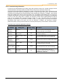
Version list
Designation of previous versions
Software
Version
Comments
BU 0240 GB, June 2010
V 1.2 R0
First version based on BU 0200 DE / 1310
Part No. 607 2401 / 2210
Publisher
Getriebebau NORD GmbH & Co. KG
Rudolf- Diesel- Str. 1 • D-22941 Bargteheide • Germany • http://www.nord.com/
Tel.: +49 (0) 45 32 / 401-0 • Fax +49 (0) 45 32 / 401-555
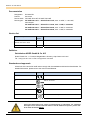
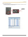
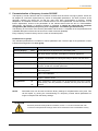
Standards and approvals
All devices of the entire SK 200E series comply with the standards and directives listed below. For
detailed information, please refer to the main manual BU0200.
Standard / Directive
Logo
Comments
EMC
EN 61800-3
UL
File No. E171342
cUL
File No. E171342
C-Tick
N 23134
RoHS
2002/95/EU RoHS compliant
NOTE
These brief instructions only contain a limited amount of information. For a detailed
description of use and the technical details of the SK 200E and its options, please refer
to the main document BU0200.
4
BU 0240 GB
Table of Contents
1 GENERAL INFORMATION ......................................................................................................6
1.1 Delivery.................................................................................................................6
1.2 Safety and installation information .......................................................................7
1.3 Wiring guidelines ..................................................................................................9
1.4 Nomenclature / type codes.................................................................................10
2 ASSEMBLY AND INSTALLATION ........................................................................................12
2.1 Installation and assembly ...................................................................................12
2.2 Electrical connection ..........................................................................................14
2.3 Electrical connection of power unit.....................................................................15
2.4 Electrical connection of SK 200E control unit ....................................................16
3 SK 200E DISPLAYS AND CONTROL ...................................................................................18
4 COMMISSIONING, SK 200E ..................................................................................................19
4.1 Commissioning stages .......................................................................................19
4.1.1 Connection..............................................................................................................19
4.1.2 Configuration...........................................................................................................20
4.1.3 Commissioning examples .......................................................................................24
4.2 ATEX Zone 22 for SK 2x5E................................................................................26
4.2.1 Modified SK 2x5E for compliance with Category 3D...............................................27
4.2.2 Options for ATEX Zone 22 3D ................................................................................27
4.2.3 Maximum output voltage and torque reduction .......................................................30
4.2.4 Commissioning information.....................................................................................31
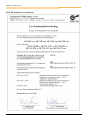
4.2.5 EC declaration of conformity ...................................................................................32
5 PARAMETERISATION OF FREQUENCY INVERTER SK 200E ..........................................33
6 OPERATING STATUS MESSAGES AND LED DISPLAYS..................................................35
7 TECHNICAL DATA FREQUENCY INVERTER......................................................................37
8 MAINTENANCE AND SERVICING INFORMATION..............................................................38
9 KEYWORD INDEX..................................................................................................................39
BU 0240 GB
5
NORDAC SK 200E Manual
1
General information
These brief instructions for the SK 200E are based on the user manual for the frequency inverter - BU0200.
In addition to information concerning safety and use, this document also contains selected information on
commissioning, as well as use of the frequency inverter in explosion hazard areas (ATEX Zone 22).
This manual is based on the device software V1.2 R0 (see P707) of the SK 200E. If the frequency inverter
uses a different software version, this may cause differences.
A detailed description of the SK 200E and its options can be found in the user manual (BU0200). This and
other documents can be downloaded free of charge from www.nord.com.
1.1 Delivery
Check the equipment immediately after delivery/unpacking for transport damage such as deformation or
loose parts.
If there is any damage, contact the carrier immediately and carry out a thorough assessment.
Important! This also applies even if the packaging is undamaged.
6
BU 0240 GB
1 General
1.2 Safety and installation information
NORDAC SK 200E frequency inverters are devices for use in industrial high voltage systems and are
operated at voltages that could lead to severe injuries or death if they are touched.
• Installation and other work may only be carried out by qualified electricians and with the
device disconnected. The operating instructions must always be available to these
persons and must be strictly observed.
• Local regulations for the installation of electrical equipment and accident prevention
must be complied with.
• The equipment continues to carry hazardous voltages for up to 5 minutes after being
switched off at the mains.
• For single phase operation (115/230V) the mains impedance must be at least 100μH for
each conductor. If this is not the case, a mains choke must be installed.
• For safe isolation from the mains, all poles of the supply cable to the frequency inverter
must be able to be disconnected.
• Even during motor standstill (e.g. caused by a release block, blocked drive or output
terminal short circuit), the line connection terminals, motor terminals and braking resistor
terminals may still conduct hazardous voltages. A motor standstill is not identical to
electrical isolation from the mains.
• Warning: with certain settings, the frequency inverter/motor can start up automatically
after the mains are switched on.
• The frequency inverter is only intended for permanent connection and may not be
operated without effective earthing connections which comply with the local regulations
for large leakage currents (> 3.5mA). VDE 0160 stipulates the installation of a second
earthing conductor or an earthing conductor cross-section of at least 10 mm2.
• Normal FI-circuit breakers are not suitable as the sole protection for three-phase
frequency inverters if the local regulations do not permit a possible DC proportion in the
fault current. According to EN 50178 / VDE 0160, the FI circuit breaker must be an allcurrent sensitive FI circuit breaker (type B).
• In normal use, NORDAC SK 200E frequency inverters are maintenance free. The
cooling surfaces must be regularly cleaned with compressed air if the ambient air is
dusty.
CAUTION
The heat sink and all other metal components can heat up to temperatures above 70°C.
When mounting, sufficient distance from neighbouring components must be maintained.
When working on the components, allow sufficient cooling time beforehand
Protection against accidental contact may need to be provided.
ATTENTION
The power unit can continue to carry voltages for up to 5 minutes after being switched off at
the mains. Inverter terminals, motor cables and motor terminals may carry voltage!
Touching open or free terminals, cables and equipment components can lead to severe injury
or death!
DANGER TO LIFE!
BU 0240 GB
Work may only be carried out by qualified specialist electricians and with the electrical supply
to the equipment disconnected!
7
NORDAC SK 200E Manual
CAUTION
Children and the general public must be kept away from the equipment!
The equipment may only be used for the purpose intended by the manufacturer.
Unauthorised modifications and the use of spare parts and additional equipment which has
not been purchased from or recommended by the manufacturer of the device may cause fire,
electric shock and injury.
Keep these operating instructions in an accessible location and give them to all operators!
WARNING
This product intended for use in an industrial environment and is subject to sales restrictions
according to IEC 61800-3. In a domestic environment, this product can cause high frequency
interference, in which case the user may be required to take appropriate measures.
An appropriate measure would be the inclusion of a recommended mains filter.
8
BU 0240 GB
1 General
1.3 Wiring guidelines
The frequency inverter has been developed for use in an industrial environment. In this environment, high
levels of electromagnetic interference can influence the frequency inverter. In general, correct installation
ensures safe and problem-free operation. To meet the limiting values of the EMC directives, the following
instructions should be complied with.
(1) Ensure that all equipment in the control cabinet is securely earthed using short earthing cables which
have large cross-sections and are connected to a common earthing point or earthing bar. It is
especially important that all control devices connected to the frequency inverters (e.g. an automation
device) are connected to the same earthing point as the inverter itself, using a short cable with large
cross-section. Flat conductors (e.g. metal clamps) are preferable, as they have a lower impedance at
high frequencies.
(2) The bonding cable of the motor controlled by the frequency inverter should be connected directly to the
earthing terminal of the associated frequency inverter. The presence of a central earthing bar in the
control cabinet and the grouping together of all bonding conductors to this bar normally ensures safe
operation.
(3) Where possible, shielded cables should be used for control loops. The shielding at the cable end
should be carefully sealed and it must be ensured that the wires are not laid over longer distances
without shielding.
The shields of analog setpoint cables should only be earthed on one side on the frequency inverter.
(4) The control cables should be installed as far as possible from power cables, using separate cable
ducts, etc. Where cables cross, an angle of 90° should be ensured as far as possible.
(5) Ensure that the contactors and brake chokes in the cabinet are interference protected, either by RC
circuits in the case of AC contactors, or by “free-wheeling” diodes for DC contactors, for which the
interference protectors must be positioned on the contactor coils. Varistors for over-voltage
limitation are also effective. This interference suppression is particularly important when the contactors
are controlled by the relay in the frequency inverter.
(6) Use screened or armoured cable for the load connections (motor cable) and earth the
screening/armour at both ends, if possible to the frequency inverter bonding.
In addition, an EMC-compliant cabling must be ensured.
The safety regulations must be complied with under all circumstances when installing the
frequency inverter!
NOTE
The control cables, line cables and motor cables must be laid separately. In no case should
they be laid in the same protective pipes/installation ducts.
The test for high voltage insulations must not be used on cables which are connected to the
frequency inverter.
ATTENTION
With the use of a ParameterBox SK PAR-3H this must never be simultaneously connected to
the frequency inverter and the PC, as potential shifts may cause damage, especially to the
PC. (See also Manual BU0040)
BU 0240 GB
9
NORDAC SK 200E Manual
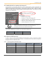
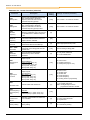
1.4 Nomenclature / type codes
Unique type codes have been defined for the individual modules and devices. These provide individual
details of the device type and its electrical data, protection class, fixing version and special versions. A
differentiation is made according to the following groups:
Group
Example of type code
Frequency inverter - basic device
SK 205E-550-323-A (-C)
Adapter unit - frequency inverter
SK TI4-1-205-1 (-C-WMK-1)
Connection unit - Technology Unit
SK TI4-TU-BUS (-C-WMK-TU)
Optional modules
SK TU4-CAO (-C-M12)
Extension modules
SK TIE4-M12-CAO
Frequency inverter
Adapter unit
The type designation resulting from this type code can be obtained from the rating plate which is attached to
or printed on the relevant module.
Example: Frequency inverter rating plate
10
BU 0240 GB
1 General
Frequency inverter type code
SK 205E-370-323-A (-C)
IP protection class: Standard = IP55, C = „coated“ IP66
Radio interference filter: O = without, A = Class A1, B = Class B1
Mains voltage: x12 = 115V, x23 = 230V, x40 = 400V
Number of mains phases: 1xx = single phase, 3xx = 3-phase
Digits before comma for power: 0 = 0.xx, 1 = 0x.x0, 2 = 0xx.0
Device nominal power: 250 = 0.25kW, 370 = 0.37kW, ... 751 = 7.5kW
Device series: SK 205E, SK 215E, SK 225E, SK 235E
(...) Options, only implemented if required.
Adapter Unit type code
SK TI4-1-205-1 (-C-WMK-1)
Wall mounting kit: -1 = S I + II, -2 = S III
IP protection class: Standard = IP55, C = „coated“ IP66
Mains connection: 1 = 1~ 115/230V*, 3 = 3~ 230/400V*
Suitable device types: 205 = SK 205E, 215 = SK 215E,
225 = SK 225E, 235 = SK 235E
Size: 1 = S I, 2 = S II, 3 = S III
Device series: SK TI4 = Connection Unit SK TI4
*) The voltage depends on the frequency inverter used;
please also refer to the technical data.
(...) Options, only implemented if required.
The description of the type codes for the options can be found in BU0200.
BU 0240 GB
11
NORDAC SK 200E Manual
2
Assembly and installation
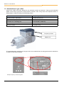
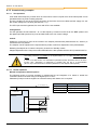
2.1 Installation and assembly
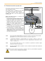
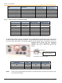
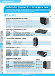
NORDAC SK 200E frequency inverters are available in various sizes depending on their output. Connection
of the SK 200E to the motor or the wall-mounting unit is made by means of the a suitable size of connection
unit SK T14-… The frequency inverter is mounted by means of integrated plug contacts.
The devices require adequate ventilation to protect against overheating.
Motor-mounted version: Here, the ventilation of the motor is integrated into the cooling concept of the FI.
Mounting must therefore always be carried out as shown in the illustration. For permanently low motor
speeds and self-ventilated motors, a reduction in power similar to the wall-mounted version must be taken
into account.
Wall-mounted version: In continuous operation (S1), mounting away from the motor causes a reduction in
the power of the FI by one power level. This means that relative to the motor, the FU must be selected one
power level larger.
NOTE
For further details of the power reduction and the possible ambient temperatures, please
refer to the technical data in BU0200
12
BU 0240 GB
2 Assembly and installation
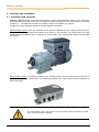
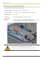
Mounting the adapter unit
For the supply of a complete drive unit (gear unit + motor + frequency inverter) the SK 200E frequency
inverter and the SK T14-... adapter unit are always completely assembled and tested. The adapter unit can
also be ordered separately for subsequent mounting on an existing motor or to replace a different motormounted frequency inverter.
NOTE
However, the IP66 compliant SK 200E must be installed by NORD, as special measures must
be implemented. IP66 components retrofitted on site cannot ensure that this protection class is
guaranteed.
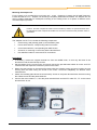
The “Adapter unit SK T14” includes the following components:
•
Cast housing, seal (already glued in) and insulation plate
•
Power terminal block, corresponding mains connection
•
Control terminal block, corresponding SK 200E version
•
Screw kit, for mounting on the motor and the terminal bars
•
Pre-fabricated cable for motor and PTC connections
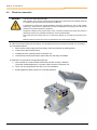
Procedures:
1.
If necessary, remove the original terminal box from the NORD motor, so that only the base of the
terminal box and the terminal strip remain.
2.
Set the bridges for the correct motor circuit and connect the pre-fabricated cables for motor and PTC
connections to the respective connection points on the motor.
3.
Mount the cast housing on the terminal box base using the existing screws and seal. Position the cast
housing with the dome facing the A-side of the motor. Check the adaptability for different motor
manufacturers.
4.
Attach the insulating plate above the terminal strip. Screw on the power terminal block above this using
the 2 M4x8 screws and the plastic washers.
5.
Connect the motor cables U, V, W to the power terminal block and the PTC cable TF+, TF- to the control
terminal block 38, 39.
BU 0240 GB
13
NORDAC SK 200E Manual
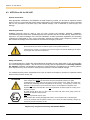
2.2
Electrical connection
WARNING
THE DEVICES MUST BE EARTHED.
Safe operation of the devices requires that is installed and commissioned by qualified personnel
in compliance with the instructions provided in this Manual.
In particular, the general and regional installation and safety regulations for work on high voltage
systems (e.g. VDE) must be complied with as must the regulations concerning correct use of tools
and the use of personal protection equipment.
Dangerous voltages can be present at the motor connection terminals even when the inverter is
switched off. Always use insulated screwdrivers on these terminal fields.
Ensure that the input voltage source is not live before setting up or changing connections to the
unit.
Make sure that the inverter and motor are specified for the correct supply voltage.
In order to access the electrical connections, the SK 200E must be removed from the SK T14 connection
unit. Proceed as follows:
1. Switch off the mains supply and if necessary check and observe the waiting period.
2. Loosen the 4 Allen screws (4mm).
3. Carefully lift the FI vertically off the connection unit.
4. The electrical connections and the option slots are now freely accessible.
To replace the FI, proceed in the opposite sequence:
5. Here, special care must be taken that the PE pins are correctly contacted.
These are located diagonally in 2 corners of the FI and the connection unit.
6. The FI can only be placed on the SK T14 in one orientation.
7. Evenly tighten the Allen screws in a cross-wise direction.
14
BU 0240 GB
2 Assembly and installation
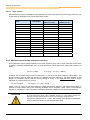
2.3 Electrical connection of power unit
L1 / L
L2 / N
L3 / PE
All connection terminals are located in the connection
unit of the frequency inverter.
One terminal block is provided for the power
connections and one for the control connections.
The earthing connections (device earthing) are
located on the base in the cast housing of the
connection unit.
PE L3 L2 L1
Before and while the device is connected, the
following must be observed:
1. Ensure that the mains supply provides the correct
voltage and is suitable for the current required.
2. Ensure that suitable circuit breakers with the
specified nominal current range are installed
between the voltage source and the inverter.
PE U V W +B -B
3. Connect the mains voltage directly to the
terminals L1-L2/N-L3 and the earth (according to
the device).
Internal or
external braking
resistor
4. To connect the motor, three flexible wires U-V-W
should be used when mounting the motor.
5. For wall-mounting a 4-conductor shielded motor
cable (recommended) to the terminals U-V-W and
earth should be used. In this case the cable
shielding should be connected to a large area of
the metallic screw connector.
NOTE:
M
3~
when using specific wiring sleeves, the maximum connection cross-section can be reduced.
Screwdriver: Use a 5.5mm slot-head screwdriver to connect the power unit.
NOTE:
If synchronous machines or several motors are connected in parallel to a device, the
frequency inverter must be switched over to linear voltage/frequency characteristic curves,
Æ P211 = 0 and P212 = 0.
NOTE:
Only use copper cables with min. 75°C or 75°C/80°C or equivalent for connection. Higher
temperature classes are permissible.
NOTE:
The use of shielded cables is essential in order to maintain the specified radio interference
suppression level.
ATTENTION: This device produces high frequency interference, which may make additional suppression
measures necessary in domestic environments.
BU 0240 GB
15
NORDAC SK 200E Manual
2.4 Electrical connection of SK 200E control unit
The control terminals are located on the inside of the frequency inverter connection unit. The connections
differ according to the version (SK 205E, 215E, 225E, 235E).
Connection terminals:
Screw terminals, 3.5 mm slot-head screwdriver
Cable cross-section:
0.2 ... 2.5mm 2, AWG 24-14, rigid or flexible, without wire end sleeves
Tightening torque
0.5 ... 0.6Nm
Control cable:
Lay and shield separately from the mains/motor cables
Control voltages,
External
18…30V, min. 200mA, the current load is increased according to the equipment.
For the supply of the FI control unit and the connected options.
NOTE
GND is a common reference potential for analogue and digital inputs.
The labelling of the control terminal bar differs according to the SK 200E version.
16
BU 0240 GB
2 Assembly and installation
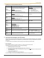
Control terminal functions
LABELLING, FUNCTION
SH:
"Safe stop" function
24V SH:
"Safe stop" input
AS:
Integrated AS interface
GND SH: "Safe stop" reference potential
24V:
External 24V power supply
SYS+/-:
System bus
GND:
Reference potential for digital signals
MB+/-:
DIN:
Digital input
Electromagnetic brake control
(105V, 180V, 205V)
DO:
Digital output
TF+/-:
Motor PTC connection
CONNECTIONS AND FUNCTIONS FOR SK 200E VERSIONS
FI type
SK 205E
SK 215E (SH)
SK 225E (AS1)
SK 235E (SH + AS1)
Pin
Labelling
1
44
2
44/84
3
40
4
40/85
5
21
DIN1 / digital input 1
6
22
DIN2 / digital input 2
7
23
DIN3, digital input 3
8
24/89
DIN4,
digital input 4
24V SH,
“Safe stop”
DIN4,
digital input 4
24V SH,
“Safe stop”
9
40/88
GND
GND SH
GND
GND SH
10
1
DO 1, digital output 1
11
40
GND
12
77
SYS+, system bus
13
78
SYS-, system bus
14
-
---
15
79
MB+, electromagnetic brake control
16
80
MB-, electromagnetic brake control
17
38
TF+, motor PTC connection
18
39
TF-, motor PTC connection
24V, external 24V FI supply*
24V, external 24V FI supply
AS+, AS- Interface
GND, reference potential for digital signals
GND
AS- Interface
*With the use of the AS interface, terminal 44 provides an output voltage (24V, max. 60mA). In this case, no voltage
sources may be connected to this terminal!
BU 0240 GB
17
NORDAC SK 200E Manual
3
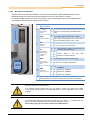
SK 200E displays and control
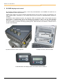
By combining different modules for display, control and parameterisation, the NORDAC SK 200E can be
easily adapted to various requirements.
Alphanumeric display and control modules (Illustration below) can be used for simple commissioning. For
more complex tasks, connection to a PC system and the use of Nord Con parameterisation software is
available.
As supplied, without additional options, the diagnostic LEDs are externally visible. These signal the actual
device status. 2 potentiometers and 8 DIP switches are provided in order to set the most important
parameters. In this minimal configuration no other adapted parameters are stored in the plug-in EEPROM.
The only exception is the data concerning operating hours, faults and fault circumstances. This data can be
stored in the EEPROM.
RJ12
LEDs
Potentiometers SK 200E mounted on motor, top view 8x DIP switches
Æ
Plug-in EEPROM
Æ SK 200E not fitted, view from inside .
Parameterisation and display options: SK CSX-3H and SK PAR-3H
18
BU 0240 GB
4 Commissioning
4
Commissioning, SK 200E
The SK 200E inverter series can be commissioned in various ways:
a) For simple applications (e.g conveyor applications) by means of the DIP switches integrated into the
SK 200E (inside) and potentiometers (externally accessible).
In this configuration the plug-in EEPROM is not required.
b) Through adaptation of parameters using software via the ParameterBox (SK CSX-3H or SK PAR3H) or NordCon PC - supported software.
Here, the parameterised data is stored in the plug-in EEPROM. This must therefore always remain
plugged in during operation.
ATTENTION
DANGER TO LIFE!
The frequency inverter is not equipped with a line main switch and is therefore always live when
connected to the power supply. Live voltages may therefore be connected to a connected motor
at standstill.
NOTE
For commissioning standard applications, a limited number of the frequency inverter inputs and
outputs (physical and I/O bits) have predefined functions. These settings may need to be
changed (Parameters (P420), (P434), (P480), (P481)).
4.1 Commissioning stages
4.1.1 Connection
After mounting the frequency inverter Adapter
Unit on the motor or the wall mounting kit, the
mains and motor cables must be connected to
the relevant terminals (PE, L1, N (/L2, L3)
und U, V, W).
L1 / L
L2 / N
L3 / PE
PE L3 L2 L1
In addition, a 24V DC control voltage supply to
the frequency inverter is essential (connection
to terminals 44/40).
In principle, the frequency inverter can be
operated in this configuration.
(See Section 4.1.3)
Terminal 21
Digital input
Terminals 38/39
TF (PTC)
Terminals 40/44
Control voltage
Terminals 79/80
Mech. brake
PE U V W +B -B
Internal or
external braking
resistor
Illustration above: Control cable connections
Illustration right:
Mains / motor cable connections
M
3~
NOTE
The necessary 24V control voltage can be implemented by in integrated SK CU4-…-24V) or an
external (SK TU4-…-24V) optional mains unit or a comparable power source (min. 200mA).
BU 0240 GB
19
NORDAC SK 200E Manual
4.1.2 Configuration
Changes to individual parameters are usually necessary for operation. (Exceptions: see Section 4.1.3 )
Configuration can be carried out to a limited extent via the DIP switches. Configuration by means of
software parameterisation is necessary for more extensive parameter changes.
NOTE
Mixing of DIP switch configuration and (software) parameterisation should be avoided.
4.1.2.1
Parameterisation
The use of a ParameterBox (SK CSX-3H / SK PAR) or NordCon software is necessary to change the
parameters.
Parameter group
Parameter numbers
Functions
Motor data
P201 … P207,
(P208)
Data on motor rating plate
P220, Function 1
Measure stator resistance
Value is written to P208
alternatively
Motor data list
Selection of a 4-pole standard
motor from a list
Motor identification
Complete measurement of a
connected motor
P200
alternatively
P220, Function 2
Remarks
Prerequisite: motor at least 3
power levels less than the
frequency inverter
Basic parameters
P102 … P105
Ramp times and frequency
limits
Control terminals
P400, P420
Analog and digital inputs
NOTE
Prior to commissioning, it should be ensured that the frequency inverter is in its default setting
(P523).
If configuration is carried out at a parameter level, the DIP switches must also be set to the
"OFF" position.
20
BU 0240 GB
4 Commissioning
4.1.2.2
DIP switch configuration
The DIP switches provide the possibility of carrying out commissioning without additional control units.
Additional settings are made using the potentiometer on the top of the frequency inverter.
As supplied, all DIP switches are at the “Off” position, which corresponds to control via the digital inputs.
The frequency setpoint value is adjusted via P1 and P2.
No.
Bit
Int RBrake
off
Behaviour corresponding to P555, P556, P557
2
Internal brake
resistor
on
Behaviour corresponding to the brake resistor
used
7
60Hz*
off
Motor data corresponding to the rated power of
the FI in kW relative to 50Hz, fmax = 50Hz
on
Motor data corresponding to the rated power of
the FI in hp relative to 60Hz, fmax = 60Hz
V/F
off
VFC regulation corresponding to P211/P212
Regulating
process
on
V/f curve ((⇒ P211=0 und P212=0)
off
off
off
on
on
off
on
on
BUS
off
Corresponding to P509 and P510 [1] [2]
Source control
word and setpoint
value
on
System bus (⇒ P509=3 and P510=3)
off
off
Corresponding to P514 and 515 [32,
250kBaud]
off
on
Address 34, 250kBaud
on
off
Address 36, 250kBaud
on
on
Address 38, 250kBaud
8
7
8‐pin DIP switch DIP switches
26
6
5
2
50/60Hz-operation
I/O
5/4
24/3
3
22
Plug‐in EEPROM 2/1
1/0
2
Potentiometer
function, digital
inputs and AS
interface
ADR
System bus
address/ baud rate
SK 200E, internal view Corresponding to P420 [1-4] and P400 [1-2]
or P480 [1-4] und P481 [1-4]
Further details in the next
(depends on the DIP3 "BUS")
table.
*) A changed setting is applied the next time the mains is switched on.
Existing settings in parameters P201-P209 and P105 are overwritten!
NOTE
FACTORY SETTING, AS DELIVERED!
*) As delivered, all DIP switches are in the “off” position. Control is by means of the digital
control signals (P420 [01]-[04]) and the potentiometers P1 and P2 integrated in the FI (P400
[01]-[02]).
NOTE
For controlling the frequency inverter via In/Out bits (e.g.: AS-i, DIG In 1 - 4) typical values are
preset in the relevant parameters (P480) and (P481). (Details: Section 5)
These settings apply to both control via AS-i bits and BUS I/O bits.
BU 0240 GB
21
NORDAC SK 200E Manual
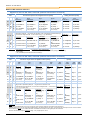
Details of DIP switches 5/4 and 3
Applies to devices SK 205E, SK 215E (without AS interface on board)
DIP
5
4
Functions as per the list of
analog functions (P400)
Functions as per the list of digital functions (P420)
3
Dig 1
Dig 2
Dig 3
Dig 4**
Poti 1
Poti 2
(P420 [01])*
off {01} "Enable R"
(P420 [02])*
{02} "Enable L"
=5Hz (P465[01])
=10Hz (P465[02])
off on off {01} "Enable R"
on off off {45} "3-on"
on on off {50} "F Arr Bit0"
{02} "Enable L"
{26} "F setpoint"
{12} "Quit"
{05} "F max"
{04} "F min"
{49} "3-off"
{47} "Freq. +"
{48} "Freq. -"
{05} "F max"
{15} "Ramp"
{51} "F Arr Bit1"
{52} "F Arr Bit2"
{53} "F Arr Bit3"
=10Hz (P465[02])
=20Hz (P465[03])
=35Hz (P465[04])
{05} "F max"
{15} "Ramp"
off off
=5Hz (P465[01])
off off on
(P420 [03])*
(P420 [04])*
{04} "Fixed freq. 1" {05} "Fixed freq. 2"
(P400 [01])*
(P400 [02])*
{01} "F setpoint" {15} "Ramp"
The functions of the digital inputs are inactive (control via system bus), however, the settings made
in parameters (P420 [01 … 04]) result in the activation of the correspondingly parameterised input,
(P400 [01])
for the functions designated with ..² in the function list (e.g.: {11}²= "Quick stop).
(P420 [01])
no function
(P420 [03])
(P420 [04])
{04} "Fixed freq. 1" {05} "Fixed freq. 2"
(P420 [02])
no function
=5Hz (P465[01])
{01} "F setpoint"
(P400 [02])
{15} "Ramp"
{01} "F setpoint"
{05} "F max"
{01} "F setpoint"
{05} "F max"
{05} "F max"
{15} "Ramp"
=10Hz (P465[02])
off on on {14} "Remote control" "Encoder track A" "Encoder track B" {01} "Enable R"
{66}
on off on {14} "Remote control" {01} "Enable R"
{10} "Block"
"F Arr Bit1"
on on on {14} "Remote control" {51}
=10Hz (P465[02])
{52} "F Arr Bit2"
"Release brake"
{53} "F Arr Bit3"
=20Hz (P465[03])
=35Hz (P465[04])
Explanation: (values underlined in brackets) = (relevant parameter / source of function), e.g.: Parameter (P420[01])
{curly brackets}
= {Function} e.g.: {01} „Enable Right“
(See also BU0200) → Table behind parameter (P420), (P400) or (P434))
* Default setting
** only if available (Devices without function "Safe Stop")
Applies to devices SK 225E, SK 235E (without AS interface on board)
DIP
5
4
Functions as per the list of digital functions (P420)
ASi
In1
3
(P480 [01])*
{01}
off off off "Enable R"
ASi
In2
(P480 [02])*
{02}
"Enable L"
ASi
In3
(P480 [03])*
{04}
"Fixed freq. 1"
ASi
In4
Functions as per the list of digital outputs
(P434)
ASi
Out1
ASi
Out2
(P480 [04])*
{12}
(P481 [01])* (P481 [02])*
{07}
{18}
"Quit"
"Error"
"Standby"
ASi
Out3
ASi
Out4
"DigIn1" "DigIn2"
=5Hz (P465[01])
{04}
{05}
off on off "Fixed freq. 1" "Fixed freq. 2"
{06}
{07}
{18}
=20Hz (P465[03])
"Fixed freq. 4" {07} "Error" "Standby"
=35Hz (P465[04])
on off off {01} "Enable R" {02} "Enable L"
{47} "Freq. +"
{48} "Freq. -"
"F Arr B1" {52} "F Arr B2"
on on off {51}
=10Hz (P465[02])
=20Hz (P465[03])
{53} "F Arr B3"
{14} "Remote
=5Hz (P465[01])
off off on
=10Hz (P465[02])
"Fixed freq. 3"
=35Hz (P465[04])
control"
{07} "Error"
{07} "Error"
{18}
"Standby"
{18}
"Standby"
The functions of the digital inputs are inactive (control via system bus), however, the
settings made in parameters (P480 [01 … 04]) result in the activation of the
(P481 [02])
correspondingly parameterised bits, for the functions designated with ..² in the function (P481 [01])
{18}
list (e.g.: {11}²= "Quick stop).
{07} "Error"
(P480 [01)
no function
(P480 [02])
no function
"Standby"
(P480 [04])
(P480 [03])
{04} "Fixed freq. 1" {12} "Quit"
"DigIn1" "DigIn2"
"DigIn1" "DigIn2"
"DigIn1" "DigIn2"
"DigIn1" "DigIn2"
=5Hz (P465[01])
{14}
{04}
off on on "Remote control" "Fixed freq. 1"
=5Hz (P465[01])
{05}
{06}
{18}
=10Hz (P465[02])
"Fixed freq. 3" {07} "Error" "Standby"
=20Hz (P465[03])
on off on "Remote control" {01} "Enable R"
{47} "Freq. +"
{48} "Freq. -"
{14}
"F Arr B0"
on on on "Remote control" {50}
=5Hz (P465[01])
{51} "F Arr B1"
{52} "F Arr B2" {07} "Error" {18}
{14}
"Fixed freq. 2"
=10Hz (P465[02])
=20Hz (P465[03])
{07} "Error"
{18}
"Standby"
"Standby"
"DigIn1" "DigIn2"
"DigIn1" "DigIn2"
"DigIn1" "DigIn2"
Explanation: See table above
Note:
The functions of potentiometers P1 and P2 correspond to those of devices without an AS interface (see table above).
With DIP switches 5 and 4 in the OFF position (default setting), the digital inputs are also active. The functions then correspond to those of devices without
an AS interface (table above). In all other DIP switch combinations the functions of the digital inputs are deactivated.
ASi OUT1 and ASi OUT2 loop the signal level (High / Low) of digital inputs 1 and 2.
22
BU 0240 GB
4 Commissioning
Details of potentiometers P1 and P2
The setpoint can be adjusted to a fixed value with the integrated potentiometer P1. Adjustment of the startup and braking ramps can be made via potentiometer P2.
Potentiometer
P2
P1
Potentiometer
P1 (continuous)
P2 (stepped)
0%
P102/103
P105
-
-
-
10%
0.2s
10Hz
1
P102/103
P104
20%
0.3s
20Hz
2
0.2s
2Hz
30%
0.5s
30Hz
3
0.3s
5Hz
40%
0.7s
40Hz
4
0.5s
10Hz
50%
1.0s
50Hz
5
0.7s
15Hz
60%
2.0s
60Hz
6
1.0s
20Hz
70%
3.0s
70Hz
7
2.0s
25Hz
80%
5.0s
80Hz
8
3.0s
30Hz
90%
7.0s
90Hz
9
5.0s
35Hz
100%
10.0s
100Hz
10
7.0s
40Hz
The function of P1 and P2 depends on DIP 4/5. The meaning
changes according to the setting.
As standard, P1 sets the setpoint value of 0-100% and P2 sets the
ramp from 0.2-7sec.
BU 0240 GB
23
NORDAC SK 200E Manual
4.1.3 Commissioning examples
4.1.3.1
Test operation
A SK 200E series frequency inverter which is to be used to control a 4-pole motor of the same power can be
operated without any aids to testing purposes.
The only condition for this is the correct connection of the mains and motor cables and the supply of a 24V
DC control voltage to the inverter (See Section 4.1.1).
The PTC input must be bypassed, if a motor with PTC is not available.
Configuration
For test operation the DIP switches 1 to 5 of the frequency inverter must be set to the "OFF" position and
the digital input DIN1 (terminal 21) must be hard-wired to the 24V control voltage.
Control
Enabling is carried out as soon as the inverter's own setpoint potentiometer (Potentiometer P1, Section ) is
moved from the 0% position.
The setpoint can be adjusted to the requirements by further continuous adjustment of the potentiometer.
Resetting the setpoint to 0% sets the frequency inverter into "Standby" status.
Stepped adjustment of the ramp times within defined limits is also possible with the aid of potentiometer P2.
NOTE
This setting method is not suitable for the implementation of a so-called "automatic start with
mains".
In order to use this function, it is essential that parameter (P428) "Automatic Start" is set to the
function "ON". Adjustment of parameters is possible with the aid of a ParameterBox
(SK xxx-3H) or with the NordCon software (Windows PC and adapter cable required).
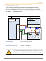
4.1.3.2
Normal operation
Minimal configuration without options
The simplest version of normal operation is implemented by the integration of a switch to enable the
controller instead of the hard wiring of the digital input 1 to 24V.
Parameter (P428) must be changed if an automatic startup with "Mains On" is required.
1/3~ 115/230/400V + PE
Function
Setpoint
Frequency ramp
L1 - L2/N - L3
Controller enable
115/230/400V
Control terminal bar
Frequency inverter
SK 2x5E-...
44
40
.
.
21
22
.
38
39
Setting
Integrated potentiometer
P1
Integrated potentiometer P2
External switch S1
24V=
GND
Switch S1
Motor PTC
24
BU 0240 GB
4 Commissioning
Minimal configuration with options
In order to implement completely autonomous operation (i.e. independent of control cables etc.) a
Potentiometer Unit (SK CU4-POT) is required. In combination with an integrated mains unit
(SK CU4-…-24V) a solution can be implemented with only one mains cable (1~ / 3~ according to the
version), and a suitable speed and direction control can be ensured (See connection example below).
This configuration method also provides the possibility of setting the frequency inverter to start automatically
with "Mains On", by changing parameter (P428).
Connection plan and parameterisation of SK CU4-POT, example
1/3~ 115/230/400V + PE L1 - L2/N - L3
L1 - L2/N
115/230/400V
115/230/400V
24V mains unit
SK CU4-24V-...
Control terminal bar
Frequency inverter
SK 2x5E-...
44
40
.
.
21
22
23
24
.
.
.
24V=
(br)
GND (bl) Control terminal bar
44 40 44 ...
11 14 12
B1
AGND
R
0-10V
L
10V=
0-100%
(br) (br) (white) (bl)
(blk) (gn)
Potentiometer
0-10
R/0/L
Switch
SK CU4-POT
DIP switch settings:
DIP3 = off, DIP4 = on, DIP5 = off
or
recommended
parameter setting, DIP1-8 = off:
P400 [07] = 1
P420 [02] = 2
P420 [01] = 1
P420 [03] = 26
NOTE
An 8-Bit A/D converter is integrated into mains units SK TU4-…-24V and SK CU4-…-24V. This
makes it possible to connect a potentiometer or other analog setpoint source to the mains unit
and to transfer this to the digital input of the frequency inverter via a corresponding pulse signal.
BU 0240 GB
25
NORDAC SK 200E Manual
4.2 ATEX Zone 22 for SK 2x5E
General information
With appropriate modification, the NORDAC SK 2x5E frequency inverter can be used in explosion hazard
areas. For this it is important that all the safety information in the operating instructions is strictly complied
with for the prevention of personal injury and material damage. This is essential to prevent injury and
damage.
Qualified personnel
Qualified personnel must be used to carry out work involving the transport, assembly, installation,
commissioning and maintenance. Qualified personnel are persons who due to their training, experience and
instruction, and their knowledge of the relevant standards, accident prevention regulations and operating
conditions are authorised to carry out the necessary activities for starting up the frequency inverter. This
also includes knowledge of first aid measures and the local emergency services.
ATTENTION
All work must only be carried out with the power to the system switched off.
If the frequency inverter is connected to a motor and a gear unit, the EX labelling of the motor
and the gear unit must also be observed.
Safety information
The increased danger in areas with inflammable dust demands the strict observation of the general safety
and commissioning information. The drive unit must comply with the specifications in Planning Guideline
No. 6052101. Explosive concentrations of dust may cause explosions if ignited by hot or sparking objects.
Such explosions may cause serious or fatal injuries to persons or severe material damage.
It is essential that the person responsible for the use of motors and frequency inverters in explosion hazard
areas is trained in their correct use.
ATTENTION
Before opening the frequency inverter for the connection of electric cables or other work, the
mains voltage must always be switched off and secured against switching on again!
Temperatures may occur within the frequency inverter and the motor, which are higher than
the maximum permissible surface temperature of the housing. The frequency inverter may
therefore not be opened or removed from the motor in an atmosphere of explosive dust!
Impermissibly heavy dust deposits must not be permitted, as these impair the cooling of the
frequency inverter!
All cable glands which are not used, must be closed with blind screw plugs which are
approved for explosion hazard areas.
Only the original seals may be used.
The protective film covering the diagnostic LEDs in TU4 modules must not be damaged.
It must be ensured that the plastic housing cover cannot be electrostatically charged by
streams of particles caused by the fan.
Repairs may only be carried out by Getriebebau NORD.
26
BU 0240 GB
4 Commissioning - ATEX
4.2.1 Modified SK 2x5E for compliance with Category 3D
For the operation of an SK 2x5E in ATEX Zone 22 only a modified frequency inverter is permissible. This
adaptation is only made at the NORD factory. In order to use the frequency inverter for ATEX Zone 22, the
standard cable gland plugs must be replaced by ATEX-approved brass plugs. Also, in addition to modified
seals, the clear plastic diagnostic plugs are replaced by aluminium/glass versions. The housing cover is also
coated with a UV-resistant paint.
II 3D Ex tD A22 IP55 T125 °C X
Categorisation:
Protection with "housing"
Procedure "A" Zone "22" Category 3D
Protection class IP55 / IP66 (according to the device)
Maximum surface temperature 125°C
Ambient temperature -20°C to +40°C
Series SK 2x5E frequency inverters and the associated options are only designed for a
degree of mechanical hazard corresponding to a low impact energy of 4J.
The frequency inverter must not be exposed to direct sunlight.
The necessary adaptations are contained in the ATEX outdoor installation kits.
Device
Kit designation
Part Number
SK 200E SI … III
SK 200E-ATEX-BGI
275274200
SK TU4-xxx
SK 200E-ATEX-TU4
275274206
4.2.2 Options for ATEX Zone 22 3D
In order to ensure an ATEX-compliant NORDAC SK 2x5E frequency inverter, the approval of optional
modules for explosion hazard areas must be observed. The following lists the various options with regard to
their approval for use in ATEX Zone 22 3D.
4.2.2.1
Technology Units for ATEX Zone 22 3D
Name
Part Number
Approved for
ATEX Zone 22 3D
SK TI4-TU-BUS(-C)
275280000 / (275280500)
x
SK TI4-TU-NET(-C)
275280100 / (275280600)
x
SK TU4-PBR(-C)
275281100 / (275281150)
x
SK TU4-CAO(-C)
275281101 / (275281151)
x
SK TU4-DEV(-C)
275281102 / (275281152)
x
SK TU4-IOE(-C)
275281106 / (275281156)
x
SK TU4-24V-123-B(-C)
275281108 / (275281158)
x
SK TU4-24V-140-B(-C)
275281109 / (275281159)
x
BU 0240 GB
Not approved for
ATEX Zone 22 3D
27
NORDAC SK 200E Manual
Name
4.2.2.2
Approved for
ATEX Zone 22 3D
Part Number
Not approved for
ATEX Zone 22 3D
SK TU4-POT-123-B(-C)
275281110 / (275281160)
x
SK TU4-POT-140-B(-C)
275281111 / (275281161)
x
SK TU4-PBR-M12(-C)
275281200 / (275281250)
x
SK TU4-CAO-M12(-C)
275281201 / (275281251)
x
SK TU4-DEV-M12(-C)
275281202 / (275281252)
x
SK TU4-IOE-M12(-C)
275281206 / (275281206)
x
Customer Units for ATEX Zone 22 3D
Name
Part Number
Approved for
ATEX Zone 22 3D
SK CU4-PBR
275271000
x
SK CU4-CAO
275271001
x
SK CU4-DEV
275271002
x
SK CU4-IOE
275271006
x
SK CU4-POT
275271207
SK CU4-24V-123-B
275271108
x
SK CU4-24V-140-B
275271109
x
SK ATX-POT
275142000
x
Not approved for
ATEX Zone 22 3D
x
The SK 2x5E for Category 3D can be equipped with an ATEX-compliant potentiometer, which can be used
to adjust a setpoint (e.g. speed) on the device. The potentiometer is used with an M20-M25 extension in
one of the M25 cable glands. The selected setpoint can be adjusted with a screwdriver. Due to the
removable screw closing cap, this component
complies with ATEX requirements. Permanent
operation may only be carried out with the cap
closed.
Setting adjustment
using a screwdriver
Potentiometer resistance 10 kOhm
NOTE:
28
Wire colours on the
potentiometer
Name
Terminal CU4-24V
Terminal CU4-IOE
Red
+10V reference
[11]
[11]
Black
AGND / 0V
[12]
[12]
Green
Analog input
[14]
[14] / [16]
For the use of a potentiometer with frequency inverter SK 2x5E a Customer Unit CU4-24V-xxx-B
or CU4-IOE is necessary.
BU 0240 GB
4 Commissioning - ATEX
4.2.2.3
Hand-held Technology Units for ATEX Zone 22 3D
All hand-held technology units are not approved for continuous use in the ATEX Zone 22 3D. The may
therefore only be used during commissioning or for maintenance purposes, if it is ensured that no explosive
dust atmosphere exists.
Name
Part Number
Approved for
ATEX Zone 22 3D
Not approved for
ATEX Zone 22 3D
SK CSX-3H
275281013
x
SK PAR-3H
275281014
x
ATTENTION
The diagnostic opening of the basic unit for the connection of a hand-held
technology unit or a PC must not be opened in an atmosphere containing
explosive dust.
4.2.2.4
Braking resistors
External braking resistors of type SK BRE4-x-xxx-xxx are not permitted for use in ATEX Zone 22 3D.
Name
Approved for
ATEX Zone 22 3D
Not approved for
ATEX Zone 22 3D
SK BRI4-1-100-100
275272005
x
SK BRI4-1-200-100
275272008
x
SK BRI4-1-400-100
275272012
x
SK BRI4-2-100-200
275272105
x
SK BRI4-2-200-200
275272108
x
SK BRE4-1-100-100
275273005
x
SK BRE4-1-200-100
275273008
x
SK BRE4-1-400-100
275273012
x
SK BRE4-2-100-200
275273105
x
SK BRE4-2-200-200
275273108
x
ATTENTION
BU 0240 GB
Part Number
If an internal braking resistor of type SK BRI4-x-xxx-xxx is used, the power limitation for
this must be activated under all circumstances. This is usually done by setting DIP
switch 8 to "ON". Alternatively, parameters (P555), (P556) and (P557) can be
parameterised with the appropriate values. Only the resistors assigned to the relevant
inverter type may be used.
29
NORDAC SK 200E Manual
4.2.2.5
Other options
M12 sockets and plugs for installation in the terminal box of the basic device or in technology units may only
be used of they are approved for use in ATEX Zone 22 3D.
Name
Part Number
Approved for
ATEX Zone 22 3D
Not approved for
ATEX Zone 22 3D
SK TIE4-WMK-1
275274000
x
SK TIE4-WMK-2
275274001
x
SK TIE4-WMK-TU
275274002
x
SK TIE4-HAN10E
275274100
x
SK TIE4-HANQ5
275274110
x
SK TIE4-SWITCH
275274610
SK TIE4-M12-M16
275274510
SK TIE4-M12-PBR
275274500
x
SK TIE4-M12-CAO
275274501
x
SK TIE4-M12-AS1
275274502
x
SK TIE4-M12-INI
275274503
x
SK TIE4-M12-IOL*
275274504
x
SK TIE4-M12-SYSM
275274505
x
SK TIE4-M12-SYSS
275274506
x
SK TIE4-M12-POW
275274507
x
x
x
* to be discontinued
4.2.3 Maximum output voltage and torque reduction
As the maximum output voltage depends on the pulse frequency to be set, in some cases the torque which
is stated in Planning Guideline 605 2101 must be reduced for values above the rated pulse frequency of
6 kHz.
For Fpuls > 6kHz:
Treduction[%] = 1% * (Fpuls – 6kHz)
Therefore the maximum torque must be reduced by 1% for each kHz pulse frequency above 6kHz. The
torque limitation must be taken into account on reaching the break frequency. The same applies for the
degree of modulation (P218). With the factory setting of 100%, in the field reduction range a torque
reduction of must be taken into account:
For P218 > 100%:
Treduction[%] = 1% * (105 – P218)
Above a value of 105%, no reduction needs to be taken into account. However, with values above 105% no
increase in torque above that of the Planning Guideline will be achieved. Under certain circumstances,
degrees of modulation > 100% may lead to oscillations and motor vibration due to increased harmonics.
ATTENTION
At pulse frequencies above 6 kHz (400/500V devices) or 8 kHz (230V) devices, the
reduction in power must be taken into account for the design of the drive unit.
If parameter (P218) is set to < 105%, the derating of the degree of modulation
must be taken into account in the field reduction range.
30
BU 0240 GB
4 Commissioning - ATEX
4.2.4 Commissioning information
For Zone 22 the cable glands must at least comply with protection class IP 55. Unused openings must be
closed with blank screw caps suitable for ATEX Zone 22 3D (minimum protection class IP 55).
The motors are protected against overheating by means of the frequency inverter. This is carried out by the
evaluation of the motor PTC by the frequency inverter. In order to ensure this function, the PTC must be
connected to the intended input (Terminal 38/39 control terminal plug connector). In addition, care must be
taken that a NORD motor from the motor list (P200) is set. If a standard 4-pole NORD motor or a motor from
a different manufacturer is not used, the data for the motor parameters ((P201) to (P208)) must be adjusted
to those on the motor rating plate. In addition, the frequency inverter must be parameterised so that the
motor can be operated with a maximum speed of 3000 1 / min . For a four-pole motor, the "maximum
frequency" must be set to a value which is smaller or equal to 100Hz ((P105) ≤ 100). Here the maximum
permissible output speed of the gear unit must be observed. In addition, the monitoring "I²t-Motor"
(Parameter (P535) / (P533)) must be switched on and the pulse frequency set to between 4 kHz and 6 kHz.
P
P
B
B
Overview of the necessary parameter settings:
Parameter
Setting value
Factory setting
Description
P105
Maximum
frequency
≤ 100 Hz
[50]
This value relates to a 4-pole motor. On principle,
the value must only be so large that a motor
speed of 3000 rpm is not exceeded.
P200
motor list
Select the appropriate
motor power
[0]
If a 4-pole NORD motor is used, the preset motor
data can be called up.
P201 – P208
Data according to rating
plate
[xxx]
If a 4-pole NORD motor is not used, the motor
data on the rating plate must be entered here.
≥ 100%
[100]
Determines the maximum possible output voltage
[6]
For pulse frequencies above 6kHz a reduction of
the maximum torque is necessary.
Motor data
P218
Degree of
modulation
P504
Pulse frequency
P533
Factor I²t-Motor
P535
I²t motor
BU 0240 GB
4kHz … 6kHz
< 100%
According to motor and
ventilation
[100]
[0]
A reduction in torque can be taken into account
with values less than 100 in the I²t monitoring.
The I²t- monitoring of the motor must be switched
on. The set values depend on the type of
ventilation and the motor used. See Planning
Guideline No.: 605 2101
31
NORDAC SK 200E Manual
4.2.5 EC declaration of conformity
32
BU 0240 GB
5 Parameterisation
5
Parameterisation of frequency inverter SK 200E
The frequency inverter, field bus and I/O -extension modules each have their own logic systems. These can
be adapted to customers' requirements by means of changeable parameters. The basic functions of the
particular modules are factory-set, so that the units have basic functionalities on delivery. Limited
adaptations of individual functions of the relevant devices can be implemented via DIP switches. For all
further adjustments, access to the parameters of the relevant device with the aid of a ParameterBox
(SK PAR-3H, SK CSX-3H) or NordCon software is essential. It should be noted that the hardware
configuration (DIP switches) has priority over configuration via software (parameterisation).
The following is a list of the most common parameters and functions. A complete list of the parameters and
a detailed description of them can be found in the main document (BU0200).
Every frequency inverter is factory-set for a motor of the same power.
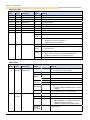
Parameter menu groups
The individual parameters are combined in various parameter sets. The first digit of the parameter number
indicates the assignment to a menu group:
Menu group
No.
Master function
Operating displays
(P0--):
For the selection of the physical units of the display value.
Basic parameters
(P1--):
Contain the basic inverter settings, e.g. switch on and switch off procedures
and, along with the motor data, are sufficient for standard applications.
Motor data
(P2--):
Settings for the motor-specific data, important for ISD current control, and
selection of characteristic curve during the setting of dynamic and static boost.
Control Parameters
(P3--):
Parameter for the adaptation of any incremental encoder used.
Control terminals
(P4--):
Analog input and output scaling, specification of digital input and relay output
functions, as well as PI controller parameters.
Additional parameters
(P5--):
Functions dealing with e.g. the BUS interface, pulse frequency or error
acknowledgement.
Positioning
(P6--):
Adjustment of the positioning function in SK 200E. For further details please
refer to Manual BU 0210.
Information
(P7--):
Display of e.g. actual operating values, old error messages, equipment status
reports or software version.
Array parameter
-01
...
-xx
Some parameters in these groups can be programmed and read in several
levels (arrays). After the parameter is selected, the array level must also be
selected.
NOTE:
Parameter P523 can be used to load the factory settings for all parameters at any time. This
can be helpful, e.g. during the commissioning of a frequency inverter whose parameters no
longer correspond with the factory settings.
ATTENTION
All current parameter settings will be overwritten, if P523= 1 is set and confirmed with "OK".
To save the actual parameter settings, these can be transferred to the ParameterBox memory.
BU 0240 GB
33
NORDAC SK 200E Manual
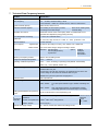
Parameter list - inverter functions (selection)
Parameter
Description
Factory
setting
Settings / functions (selection)
P102
Start-up time
Start-up time (acceleration ramp) is the
time corresponding to the linear
frequency rise from 0Hz to the set
maximum frequency (P105).
[2.00]
Note: Values < 0.1 must be avoided
P103
Braking time
The braking time (braking ramp) is the
time corresponding to the linear
frequency reduction from the set
maximum frequency (P105) to 0Hz.
[2.00]
Note: Values < 0.1 must be avoided
P104
Minimum
frequency
The minimum frequency is the
frequency supplied by the FI as soon as
it is enabled and no additional setpoint
is set.
[0]
P105
Maximum
frequency
Is the frequency provided by the FI after
it has been enabled and the maximum
setpoint value is available.
[50]
P200
motor list
If a 4-pole NORD motor is used, the
preset motor data can be called up.
[0]
P201 – P208
Motor data
If a 4-pole NORD motor is not used, the
motor data on the rating plate must be
entered here.
P220
Parameter
identification
The motor data is automatically
determined by the FI with this
parameter.
[xxx]
[0]
Select appropriate motor power
Data according to rating plate
01= only stator resistance
02= motor identification
Definition of the functions of the various
setpoint inputs
P400
Setpoint input
function
Input selection:
Poti P1 (P400, Array -01)
Poti P2 (P400, Array -02)
DIN 2 (P400, Array -06)
DIN 3 (P400, Array -07)
[xxx]
00= No function
01= Setpoint frequency
15= Ramp time (only P1 / P2)
[xxx]
00= No function
01= Enable right
02= Enable left
04= Fixed frequency
05= Fixed frequency
26= Analog function (only DIN2/3)
Definition of the functions of the various
setpoint inputs
P420
Digital input
functions
P428
Automatic start
P465
Fixed frequency /
Fixed frequency
array
P509
Control word
source
P523
Factory setting
34
Input selection:
DIN 1(P420, Array -01)
DIN 2 (P400, Array -02)
DIN 3 (P400, Array -03)
DIN 4 (P400, Array -04)
Inverter enable with "Mains On"
[0]
0= Off (enable with flank)
1= On (enable with level)
Note: one digital input must be
programmed and set to enable.
Definition of fixed frequency values
Selection:
Fixed frequency 1 (P465, Array -01)
Fixed frequency 2 (P465, Array -02)
[xxx]
Selection of the interface via which the
FI is controlled.
[0]
00= Control terminals or keyboard
01= Only control terminals
03= System bus
Frequency inverter is restored to the
factory setting
[0]
00= No change
01= Load factory setting
BU 0240 GB
6 Status messages
Parameter list - inverter information (selection)
Parameter
P700
Current
operating status
Description
Display of current messages for the actual operating
status of the frequency inverter such as errors,
warnings or the cause of a switch-on block.
Selection:
Current error (P700, Array -01)
Current warning (P700, Array -02)
Reason for switch-on block (P700, Array -03)
Settings / functions (selection)
Error group:
1 / 2 = Overtemperature of inverter / motor
3 / 4 = Overcurrent error
5
= Overvoltage error
16 = Motor phase monitoring
19…= Parameter identification error
Displays the last 5 frequency inverter errors.
P701
Last error
Selection:
Last error (P701, Array -01)
Second to last error (P701, Array -02)
See P700
Displays the firmware version / Inverter revision
P707
Software version
P708
Digital input
status
Selection:
Software version (P707, Array -01)
Revision (P707, Array -02)
Shows the switching status of the digital inputs.
Bit 0 = DIN 1
Bit 1 = DIN 2
…
Displays the measured analog input value.
6
P709
Analog input
voltage
Input selection:
Poti P1 (P400, Array -01)
Poti P2 (P400, Array -02)
DIN 2 (P400, Array -06)
DIN 3 (P400, Array -07)
P719
Actual current
Displays the actual output current.
P740
Process data
Bus In
Displays the actual control word and the setpoints.
[-01] = STW (Source P509)
[-02…-04] SW 1…3 (Source P510[-01]
[-11…-13] SW 1…3 (Source P510[-02]
P749
DIP switch status
Displays the current DIP switch setting.
Bit 0 = DIP switch 1
Bit 1 = DIP switch 2
…
Operating status messages and LED displays
The frequency inverter generates operating status messages. These messages (warnings, errors, switching
statuses, measurement data) can be displayed with parameterisation tools (e.g. ParameterBox) (Parameter
group P7xx).
To a limited extent, the messages are also indicated via the diagnostic and status LEDs.
Error messages
Errors cause the frequency inverters to switch off, in order to prevent a device fault.
The following options are available to reset a fault (acknowledge):
1. Switching the mains off and on again,
2. By an appropriately programmed digital input (P420 = Function 12),
3. By switching of the “enable” on the frequency inverter to Low (if no digital input is programmed for
acknowledgement),
4. By Bus acknowledgement or
5. by P506, the automatic error acknowledgement.
An error message can only be acknowledged if its direct cause is no longer present.
BU 0240 GB
35
NORDAC SK 200E Manual
Diagnostic LEDs
LED
Signal
Name
Colour
Description
Status
Meaning
DOUT 1
yellow
Digital output 1
on
High signal applied
DIN 1
yellow
Digital input 1
on
High signal applied
DIN 2
yellow
Digital input 2
on
High signal applied
DIN 3
yellow
Digital input 3
on
High signal applied
DIN 4
yellow
Digital input 4
on
High signal applied
TEMP
yellow
Motor PTC
on
Motor overtemperature
Chop
yellow
Brake chopper
on
Brake chopper active, brightness → degree of load
Brake
yellow
Mech. brake
on
Mech. Brake released
BUS-S
green
System bus status
off
No process data communication
Flashing
(4 Hz)
"BUS Warning"
on
Process data communication active
⇒ Reception of at least 1 telegram / s
⇒ SDO transfer is not indicated
BUS-E
green
System bus error
off
No error
Flashing
(4 Hz)
Monitoring error P120 or P513
Flashing
(1 Hz)
Error in an external system bus module
⇒ E10.0 / E10.9
⇒ Bus module Æ Timeout on the external BUS (E10.2)
⇒System bus module has a module error (E10.3)
on
System bus in state “BUS off”
Status LEDs
LED
Signal
Name
Colour
Description
Status
Meaning
DS
dual
Frequency
inverter status
off
FI not on standby,
red/green
⇒ no mains and control voltage
green on
green
flashing
FI on standby
0.5 Hz
FI is ready for switch-on
2 Hz
FI is in switch-on block
red/green
0.5 Hz
Warning
alternating
1 … 25Hz
Degree of overload of switched-on FI
green on +
red flashing
FI not on standby,
⇒ Control voltage available but no mains
voltage
AS-I
dual
red/green
AS-i status
red flashing
Error, flashing frequency → Error number
off
No voltage to the AS-i module (PWR)
green
Normal operation
red
No exchange of data
⇒ Slave Address = 0 / Slave not in LPS /
Slave with incorrect IO/ID /
Master in STOP mode / Reset active
alternately
flashing
red / green
36
Peripheral error
BU 0240 GB
7 Technical data
7
Technical Data Frequency Inverter
Function
Specification
Output frequency
0.0 … 400.0Hz
Pulse frequency
3.0 … 16.0kHz, standard setting = 6kHz
Power reduction > 8kHz for 115/230V device, >6kHz for 400V device.
Typical overload capacity
150% for 60s, 200% for 3.5s
Protective measures against
Over-heating of the frequency inverter,
overvoltage and undervoltage
Regulation and control
Sensorless current vector control (ISD), linear V/f characteristic curve,
automatic flux adaptation (energy-saving function)
Motor temperature monitoring
I2t motor, PTC / Bimetal switch
Digital input
4x, Low 0-5V, High 14-30V, Ri = 9.5kΩ, Ci = 10nF, cycle time = 4ms
Electrical isolation
Control terminals
Control outputs
digital output:
Brake rectifier:
Short-circuit, earthing fault,
overload, idling
18-30V DC (according to VI 24V), max. 200mA, max. 100kΩ load
max. 0.5A choke voltage, voltage according to mains
Interfaces
Standard:
RS 485 (USS)
RS 232 (Single Slave)
System bus
Option:
Profibus
CANopen
DeviceNet
AS Interface
Efficiency of frequency inverter
approx. 95% according to size
Storage and transport temperature
-25°C … +60/70°C
Operating / ambient temperature
-25°C … +50°C, according to operating mode (Details: see BU0200)
ATEX: -20…+40°C (Details: Section 4.2)
Long-term storage
Connect the FI and the 24V modules to the mains voltage for 60 minutes at
the latest after one year.
Connect the FI and all other modules to be supplied with 24V to the 24V
control voltage for 60 minutes at the latest after one year.
Maintain this cycle throughout the storage period.
Protection class
IP55, optional IP66
Max. mounting altitude above sea level Up to 1000m:
Waiting period between two power-up
cycles
Connection
terminals
Mains/motor/brake
resistance
1000...4000m:
1%/ 100m power reduction (up to 2000m overvoltage cat.
3)
2000...4000m:
Only overvoltage category 2 is maintained, external
overvoltage protection at the mains input is necessary
60 sec for all devices in normal operating cycle
4mm2 flexible with wiring sleeves, 6mm2 with rigid cable
Control unit /System bus 2.5mm2, with1.5mm2 wiring sleeves
RS485 / RS232
External 24V supply voltage
BU 0240 GB
No power reduction
Terminal screw
tightening
torque
1.2...1.5Nm
1x RJ12 (6-pin)
18…30V DC, at least 200...800mA according to load
37
NORDAC SK 200E Manual
8
Maintenance and servicing information
In normal use, NORDAC SK 200E frequency inverters are maintenance free. Please note the "General
Data".
If the frequency converter is being used in a dusty environment, then the cooling-vane surfaces should be
regularly cleaned with compressed air. If air intake filters have been built into the control cabinet, then these
should also be regularly cleaned or replaced.
If you contact our technical support, please have the precise device type (rating plate/display), accessories
and/or options, the software version used (P707) and the series number (rating plate) at hand.
Repairs
The device must be sent to the following address if it needs repairing:
NORD Electronic DRIVESYSTEMS GmbH
Tjüchkampstraße 37
26605 Aurich, Germany
For queries about repairs, please contact:
Getriebebau NORD GmbH & Co. KG
Telephone: 04532 / 401-515
Fax: 04532 / 401-555
If a frequency inverter is sent in for repair, no liability can be accepted for any added components, e.g. such
as mains cables, potentiometer, external displays, etc.!
Please remove all non-original parts from the frequency inverter.
NOTE
If possible, the reason for returning the component/device should be stated. If necessary, at
least one contact for queries should be stated.
This is important in order to keep repair times as short and efficient as possible.
On request you can also obtain a suitable return goods voucher from Getriebebau NORD.
Internet information
You can find the comprehensive manuals in German and in English on our Internet site.
www.nord.com
38
BU 0240 GB
9 Keyword index
9
Keyword index
A
I
Address ...................................... 38
IEC 61800-3 ................................. 8
Array parameter ......................... 33
Installation .................................. 12
AS Interface ............................... 36
Installation notes .......................... 7
ATEX Zone 22, Cat. 3D ............. 26
Installing the SK 200E ................ 13
Internet ....................................... 38
Q
Queries .......................................38
R
Reference voltage.......................16
Repairs .......................................38
C
Commissioning........................... 19
L
Control connection ..................... 16
Long-term storage ...................... 37
Control terminals ........................ 17
Low Voltage Directive................... 2
S
Safety information.........................2
Service........................................38
Setup altitude..............................37
Control voltages ......................... 16
M
SimpleBox ..................................18
Maintenance............................... 38
SK ATX-POT ..............................28
Diagnostic LEDs......................... 23
Menu group ................................ 33
Status LED .................................36
DIP switches .............................. 21
Messages ................................... 35
Storage .......................................37
Display ....................................... 18
Minimal configuration ................. 24
Synchronous machines ..............15
D
E
O
T
Electrical connection .................. 14
Operating status ......................... 35
Technical Data............................37
Error messages.......................... 35
Operation.................................... 18
Type code...................................10
Optional ATEX modules ............. 27
F
Faults ......................................... 35
FI-circuit breakers ........................ 7
W
P
ParameterBox ............................ 18
Warnings ....................................35
Wiring guidelines ..........................9
Parameterisation ........................ 33
Potentiometer ............................. 16
Potentiometers P1 and P2.......... 23
Power-up cycles ......................... 37
BU 0240 GB
39
Part No. 607 2402 / 2210