1
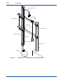
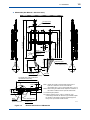
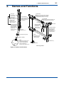
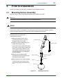
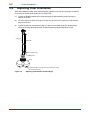
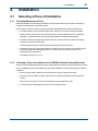
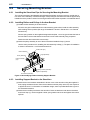
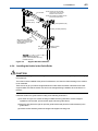
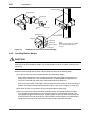
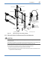
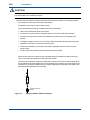
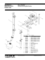
User’s Manual PB360G Vertical Floating Ball Holder IM 19H1E2-01E R IM 19H1E2-01E 4th Edition i <INTRODUCTION> INTRODUCTION The PB360G vertical floating ball holder is used to hold all types of solution analysis sensors. This holder will keep the sensor immersed in the solution at all times for continuous measurement regardless of major changes in the level of the solution to be measured. To fully exploit the capabilities of this product, thoroughly read through the User’s Manual before use. Throughout this User’s manual, important items with respect to handling are indicated by a Warning or Caution designation, depending upon the relative degree of importance. For safety reasons and to prevent the possibility of damaging the product, user should strictly observe these items. 1. Specification check The arm pipe of the PB360G vertical floating ball holder is made either of PVC or SUS304 and is either 2.5 or 3.5 m long. Upon taking receipt of the product, unpack carefully, checking that no damage has occurred during transport. Check the parts list at the end of this manual to ensure that the received product is exactly what was ordered and that no parts are missing. 2. Contents This manual covers all of the information for handling the PB360G vertical floating ball holder, including installation, inspection and maintenance. For details related to handling of the PB360G, refer to the attachments. For detailed information, refer to the User’s Manual supplied with products. Model Title IM No. DO402G Dissolved oxygen converter IM 12J05D02-01E DO30G Dissolved oxygen sensor IM 12J5B3-01E DO70G Optical Dissolved Oxygen Sensor IM 12J05D04-01E SS400G MLSS converter IM 12E6B1-02E SS300G MLSS sensor IM 12E6C1-01E SS350G Wiper-Washing controller IM 12E6E1-01E PH8ERP KCl Refillable type pH Sensor IM 12B7K1-02E PH8EFP KCl Filling type pH Sensor IM 12B7J1-01E FLXA202, FLXA21 2-Wire Liquid Analyzer IM 12A01A02-01E PH450G pH/ORP Converter IM 12B07C05-01E OR8EFG KCl Filling type OPR Sensor IM 12C07J01-01E OR8ERG KCl Refillable type OPR Sensor IM 12C04K01-01E Media No. IM 19H1E2-01E 4th Edition : Oct. 2015 (YK) All Rights Reserved Copyright © 1998, Yokogawa Electric Corporation IM 19H1E2-01E ii <INTRODUCTION> For the safe use of this equipment n Safety, Protection, and Modification of the Product • In order to protect the system controlled by the product and the product itself and ensure safe operation, observe the safety precautions described in this user’s manual. We assume no liability for safety if users fail to observe these instructions when operating the product. • If this instrument is used in a manner not specified in this user’s manual, the protection provided by this instrument may be impaired. • Be sure to use the spare parts approved by Yokogawa Electric Corporation (hereafter simply referred to as YOKOGAWA) when replacing parts or consumables. • Modification of the product is strictly prohibited. • The following symbols are used in the product and user’s manual to indicate that there are precautions for safety: n Notes on Handling User’s Manuals • Please hand over the user’s manuals to your end users so that they can keep the user’s manuals on hand for convenient reference. • Please read the information thoroughly before using the product. • The purpose of these user’s manuals is not to warrant that the product is well suited to any particular purpose but rather to describe the functional details of the product. • No part of the user’s manuals may be transferred or reproduced without prior written consent from YOKOGAWA. • YOKOGAWA reserves the right to make improvements in the user’s manuals and product at any time, without notice or obligation. • If you have any questions, or you find mistakes or omissions in the user’s manuals, please contact our sales representative or your local distributor. n Warning and Disclaimer The product is provided on an “as is” basis. YOKOGAWA shall have neither liability nor responsibility to any person or entity with respect to any direct or indirect loss or damage arising from using the product or any defect of the product that YOKOGAWA can not predict in advance. IM 19H1E2-01E iii <INTRODUCTION> n Symbol Marks Throughout this user’s manual, you will find several different types of symbols are used to identify different sections of text. This section describes these icons. WARNING Indicates a potentially hazardous situation which, if not avoided, could result in death or serious injury. CAUTION Indicates a potentially hazardous situation which, if not avoided, may result in minor or moderate injury. It may also be used to alert against unsafe practices. IMPORTANT Indicates that operating the hardware or software in this manner may damage it or lead to system failure. NOTE Draws attention to information essential for understanding the operation and features. Tip This symbol gives information that complements the current topic. SEE ALSO This symbol identifies a source to be referred to. IM 19H1E2-01E iv <INTRODUCTION> After-sales Warranty n Do not modify the product. n During the warranty period, for repair under warranty consult the local sales representative or service office. Yokogawa will replace or repair any damaged parts. Before consulting for repair under warranty, provide us with the model name and serial number and a description of the problem. Any diagrams or data explaining the problem would also be appreciated. l If we replace the product with a new one, we won’t provide you with a repair report. l Yokogawa warrants the product for the period stated in the pre-purchase quotation Yokogawa shall conduct defined warranty service based on its standard. When the customer site is located outside of the service area, a fee for dispatching the maintenance engineer will be charged to the customer. n In the following cases, customer will be charged repair fee regardless of war- ranty period. • Failure of components which are out of scope of warranty stated in instruction manual. • Failure caused by usage of software, hardware or auxiliary equipment, which Yokogawa Electric did not supply. • Failure due to improper or insufficient maintenance by user. • Failure due to modification, misuse or outside-of-specifications operation which Yokogawa does not authorize. • Failure due to power supply (voltage, frequency) being outside specifications or abnormal. • Failure caused by any usage out of scope of recommended usage. • Any damage from fire, earthquake, storms and floods, lightning, disturbances, riots, warfare, radiation and other natural changes. n Yokogawa does not warrant conformance with the specific application at the user site. Yokogawa will not bear direct/indirect responsibility for damage due to a specific application. n Yokogawa Electric will not bear responsibility when the user configures the product into systems or resells the product. n Maintenance service and supplying repair parts will be covered for five years after the production ends. For repair for this product, please contact the nearest sales office described in this instruction manual. IM 19H1E2-01E v <CONTENTS> PB360G Vertical Floating Ball Holder IM 19H1E2-01E 4th Edition CONTENTS INTRODUCTION....................................................................................................i For the safe use of this equipment....................................................................ii After-sales Warranty...........................................................................................iv 1. Overview..................................................................................................... 1-1 1.1 Features of PB360G Vertical Floating Ball Holder......................................... 1-1 1.2 Specifications..................................................................................................... 1-3 1.2.1 Standard Specifications...................................................................... 1-3 1.2.2 Model and Suffix codes...................................................................... 1-3 1.2.3 External Dimensions........................................................................... 1-4 2. Names and Functions............................................................................... 2-1 3. Prior to Installation.................................................................................... 3-1 3.1 Mounting Sensor Assembly............................................................................. 3-1 3.2 Adjusting Float Orientation.............................................................................. 3-2 4.Installation.................................................................................................. 4-1 4.1 4.2 Selecting a Place of Installation....................................................................... 4-1 4.1.1 Selecting Measurement Point............................................................. 4-1 4.1.2 Selecting a Place of Installation for the PB360G Vertical Floating Ball Holder.................................................................................................. 4-1 Securing Mounting Bracket.............................................................................. 4-2 4.2.1 Installing the Stanchion Pipe for Securing the Mounting Bracket...... 4-2 4.2.2 Installing Rollers and Pulleys in the Arm Bracket............................... 4-2 4.2.3 Installing Support Bracket to the Stanchion........................................ 4-2 4.2.4 Installing the Holder in the Guide Roller............................................. 4-3 4.2.5 Installing Balance Weight................................................................... 4-4 4.2.6 Moving the Holder to the Measurement Point and Adjustments........ 4-5 5.Maintenance............................................................................................... 5-1 5.1 Sensor Maintenance.......................................................................................... 5-1 5.2 Other Fixture Inspections................................................................................. 5-1 5.3 Sensor Retaining O-ring................................................................................... 5-2 Customer Maintenance Parts List.......................................CMPL 19H01E02-01E Revision Information................................................................................................i IM 19H1E2-01E Blank Page < 1. Overview > 1-1 1. Overview 1.1 Features of PB360G Vertical Floating Ball Holder ● Stable measurements even if solution level changes The PB360G vertical floating ball holder holds a ball that floats on the surface. The float rises and falls with the changes in the height of the solution level to ensure that the built-in sensor is always in contact with the solution allowing stable and continuous measurements. Since the float is attached to a vertical arm pipe by means of a guide roller, the measurement point is always the same. ● Installations can be made in cramped spaces and the place of installation can be adjusted ● The PB360G vertical floating ball holder can be installed in locations where the PB350G angled floating ball holder cannot be used (for example in small openings which are provided by covers or when the measurement point is close to the place of installation). The 400 mm width of the holder installation location can be adjusted in 50 mm increments. Long maintenance intervals make for ease of maintenance The sensor is inserted in the float whose spherical surface is in contact with the solution. Thus there are no corners or protrusions on the sensor where dirt or sediment can accumulate. Maintenance can therefore be performed in conjunction with the periodically performed calibration. This also makes it is easy to move the float assembly to whatever location is used for the maintenance work. . The features of the PB360G vertical floating ball holder renders it ideal for waste water processing and other unattended operations. IM 19H1E2-01E 1-2 < 1. Overview > (Sensor cable) Arm bracket Pulley Pipe assembly Guide roller Rope Auxiliary bracket Holder assembly Guide pipe Balance weight (Stanchion) Float ball Figure 1.1 IM 19H1E2-01E External View of PB360G Vertical Floating Ball Holder 1.2 1-3 < 1. Overview > Specifications 1.2.1 Standard Specifications Applicable sensors: General pH Sensor PH8ERP, PH8EFP, General ORP Sensor OR8ERG, OR8EFG, Dissolved Oxygen Sensor DO30G, DO70G, MLSS Sensor SS300G Note 1: When using a KCl filling type sensor, a stanchion or mounting bracket for the KCl tank is required separately. Note 2: Not applicable for special pH/ORP sensor or PH4/OR4 sensor. Mounting: 2-inch pipe vertical mounting (Note) Make sure the mounting pipe firmly installed. Material: Holder; ABS resin, brass, and rigid PVC O-ring; Nitrile rubber (NBR) Arm; rigid PVC or stainless steel (equivalent to SUS304) Guide-pipe; Stainless steel (equivalent to SUS304) Mounting bracket; Stainless steel (equivalent to SUS304), Roller, Pulley; Balance Weight; Stainless steel (equivalent to SUS304) Rope; Connection Supporter; Stainless steel (equivalent to SUS304) Weight: Holder, guide-pipe, and arm; Polypropylene Vinyl Covered Stainless steel (equivalent to SUS304) Approx. 7.4 kg (model PB360G-PV-25-NN) Approx. 8.8 kg (model PB360G-PV-35-NN) Approx. 8.0 kg (model PB360G-S3-25-NN) Approx. 9.6 kg (model PB360G-S3-35-NN) Mounting bracket (including assist bracket and U-bolt assembly); Approx. 5 kg x 2 sets Roller assembly (including mounting bolt assembly); Approx. 3.3 kg x 2 sets Pulley assembly (including mounting bolt assembly); Approx. 0.5 kg Connection supporter; Approx. 0.5 kg Balance weight; Approx. 3 kg (model PB360G-uu-25-NN) Approx. 4.5 kg (model PB360G-uu-35-NN) Rope (including bolt clip); Approx. 85 g (model PB360G-uu-25-NN) Approx. 97 g (model PB360G-uu-35-NN) Temperature range: 0 to 50 °C (Note) The temperature may be limited by the specifications of the sensor. Flow rate: 20 to 100 cm/s (The arm must not be distorted significantly). (Note) The flow speed may be limited depending on the specifications of the sensor. 1.2.2 Model and Suffix codes Model PB360G Arm Material Pipe Length — Option Description Code .............................. ................ Vertical floating ball holder -PV ................ PVC -S3 ................ Stainless steel -25 ................ 2.5m -35 ................ 3.5m -NN ................ Always -NN Suffix Code IM 19H1E2-01E 1-4 < 1. Overview > 1.2.3 External Dimensions l PB360G-PV (Arm Material : PVC) Ceiling Arm pipe (ø48) 1300 minimum 1200 650 .5° 22 650 L1650 (L1+510)±50 ø60 (Note 1) Counterweight (n x 1.5kg) L1+700 minimum A L2 A 400 L1-1500 (MAX.) (Note 2) Saddle band Stanchion pipe ø60.5 2-inch (prepared by user) Flow Sensor tip (Allow to face downstream) Float ball ø230 Must allow the guide roller to open/close smoothly 970 70 98 61 106 173 Pulley 300 to 100 (Pitch 50) R235 Installation space of float ball Figure 1.2 IM 19H1E2-01E 735 to 335 (Pitch 50) Note 1: Adjust the weight so that the fluid surface level is equal to or above the center of the float ball. (Two weights when L1=2.5 m; three weights when L1=3.5 m) Note 2: Before fixing the saddle band, adjust the orientation of the holder so that the sensor tip faces downstream. L1= Holder length specified L2= Half the maximum span +150 mm. However, if the counterweight touches the stanchion pipe installed, adjust the position of the pulley so that the counterweight can freely move up and down inside the tank. Section A-A External dimensions of PB360G-PV F140.ai < 1. Overview > 1-5 lPB360G-S3 (Arm Material : Stainless Steel) Ceiling Arm pipe (ø34) .5° 1200 (Note 2) Saddle band 400 L1-1500 (MAX.) 22 650 (Note 1) Counterweight (n x 1.5kg) 1300 minimum L2 650 L1±10 (L1+510)±10 ø60 L1+700 minimum A A Stanchion pipe ø60.5 2-inch (prepared by user) Flow Sensor tip (Allow to face downstream) Float ball ø230 The guide roller must be able to be opened/closed smoothly. 970 70 173 106 98 61 Pulley 300 to 100 (Pitch 50) R235 Installation space of float ball Figure 1.3 735 to 335 (Pitch 50) Note 1: Adjust the weight so that the fluid surface level is equal to or above the center of the float ball. (Two weights when L1=2.5 m; three weights when L1=3.5 m) Note 2: Before fixing the saddle band, adjust the orientation of the holder so that the sensor tip faces downstream. L1= Holder length specified L2= Half the maximum span +150 mm. However, if the counterweight touches the stanchion pipe installed, adjust the position of the pulley so that the counterweight can freely move up and down inside the tank. Section A–A F141.ai External dimensions of PB360G-S3 IM 19H1E2-01E Blank Page 2. 2-1 < 2. Names and Functions > Names and Functions Arm pipe Guide roller (contains the sensor cable) Guide pipe (Equipped with a detent so that the float ball can be secured at the angle it is in contact with the solution.) Pipe assembly (Ensures that the lower and upper arm bracket connections are parallel.) Arm bracket (Secures the components held by the holder assembly to the stanchion.) Pulley Holder assembly (secures the float at the measurement point even during solution flow. It also maintains the sensor in optimum orientation.) (Raises or lowers the holder assembly depending on solution level. It is also equipped with the pulley of the rope.) Balance weight (compensates for lack of float capacity in the holder assembly.) Eye nut (holds the rope.) (Float securing nut) (Sensor holder) Auxiliary bracket (Secures the arm bracket when the arm bracket is turned to the place of maintenance.) Rope (Connects the hold assembly and the balance weight.) Float (Floats on the solution to be measured and keeps the sensor in contact with the solution regardless of changes in the solution level.) U-bolt (Stanchion) Bolt clip Mounting bracket Figure 2.1 Names and Functions IM 19H1E2-01E Blank Page 3. < 3. Prior to Installation > 3-1 Prior to Installation Perform the following process prior to installing the vertical floating ball holder. 3.1 Mounting Sensor Assembly Mount the sensor in the vertical floating ball holder before installing the holder. SEE ALSO See separate manual for information on how to assemble the sensor. NOTE Be sure not to damage the front end of the sensor. Note that the conditions of installation of some sensors may be restricted (for example, orientation relative to solution liquid flow). Check the user’s manual supplied with the sensor. Install the sensor according to the instructions given below. (1)Make sure that there is an O-ring (to secure the sensor) on the inner diameter of the sensor holder. Holder assembly (2)Thread the sensor cable through the holder assembly (arm pipe). When there is dirt or water drops inside the holder, cover the sensor cable ends with a polyvinyl bag to make sure that the insulation resistance does not drop. This will also protect it from damages during installation. (3)Press the sensor into the holder assembly (arm pipe) until the flange is flush with the sensor holder. (4)Mount the float on the holder assembly. (Sensor cable) Insert the float into the sensor holder and properly tighten the float securing nut. (Sensor holder) (Float securing nut) O-ring (Flange) Sensor Float ball Figure 3.1 Mounting the Sensor IM 19H1E2-01E 3-2 < 3. Prior to Installation > 3.2 Adjusting Float Orientation While the installation location of the holder assembly, adjust the arm pipe and guide pipe so that the front end of the sensor faces the direction of solution flow. (1) Loosen the saddle band bolt and nut that secures the holder assembly guide pipe using a spanner or the like. (2) Since the float turns with the arm pipe, turn the arm pipe so that the sensor front end faces the flow of the solution. (3) Tighten the bolt and nut loosened in Step (1) above to secure the guide pipe. Note that they should be properly tightened and that excessive tightening may damage the arm pipe. Arm pipe Guide pipe Bolt, nut (M10, M4) Saddle band Float Adjust the angle so that the front end of the sensor faces the flow of the solution. Figure 3.2 IM 19H1E2-01E Adjusting Float-Solution Contact Angle 4-1 < 4. Installation > 4.Installation 4.1 Selecting a Place of Installation 4.1.1 Selecting Measurement Point Install the PB360G vertical floating ball holder so that the float assembly in the sensor assembly is located at the designated measurement point. Under normal conditions, select a measurement point that satisfies the following requirements. § A location where a typical measured value of the solution to be measured can be obtained Avoid locations where the solution to be measured is unevenly distributed since it will lead to hunting for a measured value. Also avoid locations where air bubbles are generated. § A location where the temperature and flow rate of the measured solution matches the usage conditions of the sensor and holder A fast flowing solution that contains sand may damage the sensor front end. § The distance from the surface that supports the stanchion to the surface of the solution should equal the (length of the specified pipe) less 1.5 m when the surface of the solution to be measured is at its lowest point. For details, see Figure 1.2 to 1.3. 4.1.2 Selecting a Place of Installation for the PB360G Vertical Floating Ball Holder Sensors must be calibrated regularly and any dirt that attaches itself to the sensor should be removed. Thus the PB360G vertical floating ball holder should be installed in locations that satisfy the following conditions. § Space enough to allow calibration and maintenance near the measurement point. § No structures that prevent moving the float from the measurement point to the maintenance location. Note: To move the float, turn the arm bracket 360° round the stanchion pipe. § It must be easy to manipulate the lock pin in the mounting bracket. IM 19H1E2-01E 4-2 < 4. Installation > 4.2 Securing Mounting Bracket 4.2.1 Installing the Stanchion Pipe for Securing the Mounting Bracket The mounting bracket of the PB360G vertical floating ball holder can be secured to a vertical pipe (2inch: 60.5 mm in diameter) of sufficient strength. Set up this pipe first. Make sure that the pipe is firmly installed since the position chosen for securing the float holder will be exposed to considerable stress. 4.2.2 Installing Rollers and Pulleys in the Arm Bracket (1)Install the roller assembly in the arm bracket. Since the arm pipe is held between the roller assembly guide rollers, install the roller assembly while minding sensor position (the range of installation is shown in Subsection 1.2.3 “External Dimensions”). Place a spring washer on the supplied hexagonal bolts (M18, 14 mm long) and insert the bolts in the bolt holes in the arm bracket and screw them into the roller assembly using a spanner. Attach the other arm bracket in the same ways. (2)Attach the pulley assembly to one of the arm brackets installed in Step (1) above. Use the same procedure as in installing the roller assembly in Step (1). The place of installation is shown in Subsection 1.2.3 “External Dimensions”. Guide roller (PP) Roller assembly Cover (SUS304) Angle (SUS304) Pulley assembly (PP) Spring washer (SUS304) Arm bracket (SUS304) M8 bolt (SUS304) Figure 4.1 Assemblying Holder Assembly Support Bracket 4.2.3 Installing Support Bracket to the Stanchion (1)Attach the two arm brackets assembled in Section 4.2.2 to the stanchion using the supplied Ubolts, spring washers and nuts. Place the arm bracket with the pulley at the top. Use a spanner to tighten the nuts. For information on installation height, see the specified dimensions given in the external dimensions. (2)Attach the two auxiliary brackets to the stanchion. Place the brackets under the arm brackets and, like in Step (1), use the supplied U-bolts, spring washers and nuts and tighten them with a spanner. IM 19H1E2-01E 4-3 < 4. Installation > Arm bracket Pipe assembly (SUS304, Ø18) Note: Loosen the arm bracket U-bolt only when the arm bracket is to be turned. Note: The auxiliary brackets should be secured at all times. Pulley U-bolt (SUS304, M8) Auxiliary bracket (SUS304) When this arm bracket is pulled or pushed, the upper arm bracket moves in the same direction. Nut (SUS304, M8) Spring washer (SUS304) Stanchion A pipe of sufficient strength (2-inch, outer diameter: 60.5 mm) installed vertically. Figure 4.2 Support Bracket Installation 4.2.4 Installing the Holder in the Guide Roller CAUTION Observe the following instructions during the installation work to ensure safety and prevent damaging the equipment. The holder must be installed at the place of maintenance; not when the float is floating on the solution to be measured. Take care not to get your hands caught between the rollers when the holder is attached to the roller support. Make sure that the sensor front end is not damaged during installation when the float is on the floor. Install the holder in the guide roller according to the following instructions. (1)As shown in Figure 4.3, loosen the wing nut attached to the guide roller, move the stopper upwards to free the roller. (Free both the upper and lower guide rollers). (2)Move the wing bolt to the right to open the guide bracket and place the holder assembly in the guide rollers. (3)Close the roller assembly, attach the stoppers and tighten the wing nuts. IM 19H1E2-01E 4-4 < 4. Installation > Holder assembly Guide bracket Guide roller Wing nut Stopper Guide bracket (See Note.) Enlarged drawing Stopper Flat washer Flat washer Spring washer Wing nut Figure 4.3 Note: Make sure all washers are installed as shown before tightening the wing nut. Installation and removal of Holder Assembly 4.2.5 Installing Balance Weight CAUTION Take proper safety precautions in performing this procedure to prevent injuries and maintain safety. Take care not to drop the balance weight. Use an appropriate tool (a pair or nippers or the like) to cut off the rope. Attach the balance weight to the holder, roller and pulley according to the following steps. (1)Cut the rope that connects the holder assembly and the balance weight. Determine the length of the rope according to the roller and pulley position as well as the “L2” length given in Subsection 1.2.3 “External Dimensions” so that the balance weight does not come into contact with the pulley or the surface that supports the stanchion. First cut the rope leaving a safe margin, then place the float in the solution to check the optimum position of the balance weight before making the final cut. Use a pair of nippers to cut the rope. (2)As shown in Figure 4.4 (a) place the rope in the guide rollers and the pulley. (3)Secure one end of the rope to the holder assembly and the other end to the balance weight. First, thread the rope through the eye nut (see (b) in Figure 4.4) of the holder assembly. Use the supplied bolt clips to secure the rope. Properly tighten the bolt clips around 30 mm from the end of the loop in the rope (50 to 60 mm). Then thread the rope through the ring in the balance weight. Secure the rope in the same way as it was secured to the holder assembly. IM 19H1E2-01E 4-5 < 4. Installation > (Sensor cable) Holder assembly Rope Arm assembly Pulley Pipe assembly Guide roller Rope Auxiliary bracket Bolt clip (SUS304, M10) Eye nut (SUS304, M10) Guide roller Balance weight (SUS304) Two pieces when 2.5 m, Three pieces when 3.5 m. Balance weight Rope (Stanchion) Secure the bolt clip 30 mm from the end of the loop Float ball (a) Attaching the rope Figure 4.4 (b) Securing the rope Attaching the Rope and the Balance Weight 4.2.6 Moving the Holder to the Measurement Point and Adjustments CAUTION Make sure that U-bolts in the upper and lower auxiliary brackets before moving the holder to the measurement point. If the holder is moved when it is not properly secured by the auxiliary brackets, the arm brackets could fall off causing damage to the float and the mounting bracket. It could also cause injury. Move the holder to the measurement point according to the following instructions. (1)Loosen the U-bolts that secure the upper and lower arm brackets. (2)Hold the hold assembly arm pipe and turn the arm bracket from the place of maintenance until it is right above the measurement point. IM 19H1E2-01E 4-6 < 4. Installation > CAUTION The holder assembly is fairly heavy (7.4 kg to 9.6 kg). Therefore two people or more are required to move the holder to the measurement point. (3)Slowly lower the holder so that the float is gently placed on the solution. Then properly tighten the U-bolts both in the upper and lower arm brackets. The holder is now ready to make measurements. Check the following measuring conditions and correct if necessary. § Half or 2/3 of the float should be under water. § The sensor front end must be in the right position so as not to be effected by bubbles. §The front end of the sensor must not be installed at a location where it is exposed to air bubbles. §The balance weight must not come into contact with the surface that supports the stanchion regardless of how high the level of the solution rises. §The float must always be immersed in the solution regardless of how low the level of the solution drops. § The flow rate of the solution must not excessively bend the holder. When the flow rate of the solution is high, add extra weight to the balance weight as shown in Figure 4.5 so that 2/3 of the float is immersed in the solution. The bottom of the balance weight is provided with a screw hole to screw on extra weights. Note that an adhesive has been applied (for hermetic sealing) to the threads. Thus if the weight is just screwed on, it will not be possible to remove it again (wash away the adhesive with water or the like if permanent attachment is not desired). Additional balance weight Figure 4.5 Adjusting Additional Balance Weights IM 19H1E2-01E 5-1 < 5. Maintenance > 5.Maintenance As long as measurements are performed normally, there is no need to inspect the PB360G vertical floating ball holder. The maintenance work described in this chapter should be performed during calibration or sensor maintenance. 5.1 Sensor Maintenance The holder assembly and the arm bracket mounting bracket are exposed to stress during maintenance or the flow of the solution to be measured. If the saddle band (securing the holder assembly) and U-bolts (securing the arm brackets) are not properly tightened, sensor orientation will change with the movements of the holder assembly and arm brackets thus preventing good measurement result. Make sure that the sensor is secured correctly to allow optimum measurement results. Check for looseness in the U-bolts and the saddle band and tighten as necessary. 5.2 Other Fixture Inspections Loose roller assembly wing nuts, cover bolts (that prevent the pulley assembly rope from coming off) and bolt clips (that secure the rope) could cause an accident. Check these bolts for looseness and tighten as necessary. Make sure that the stoppers in the roller assembly have been properly locked. IM 19H1E2-01E 5-2 < 5. Maintenance > 5.3 Sensor Retaining O-ring The O-ring inside the sensor holder holds the sensor at the center of the float insertion hole and reduces the risk that dirt and air bubbles will affect the measurements. Check the O-ring for damage during sensor inspection. Replace it with a new O-ring if it is excessively damaged (one spare O-ring is supplied). Sensor retaining O-ring Float color fading The color of the float fades when it is used in a location that is exposed to direct sunlight. Color fading does not mean that the material is severely weakened and does not prevent continued use of the float. Figure 5.1 IM 19H1E2-01E Replace the O-ring with the spare O-ring when it is excessively damaged. Sensor Retaining O-ring Replacement Customer Maintenance Parts List Model PB360G Vertical Floating Ball Holder 3 4 5 10 2 6 7 8 9 11 Item Part No. 1 2 K9433AE K9433EC K9433ED K9433EE K9433EF K9433HA K9433HB K9433HC K9433HD 3 4 5 6 K9433FA K9433FD K9433FV K9433FP L9826AL 2 2 2 1 2 Arm Bracket Roller Assembly (for PVC) Roller Assembly (for SUS) Pulley Assembly Bracket 7 8 9 10 11 K9433CX Y9814NU Y9800SU K9433GR K9433GJ 4 6 6 1 1 U-bolt Assembly Bolt Spring Washer Pipe Assembly Rope Assembly (for 2.5m) K9433GK K9433GA K9433GB K9433GD K9433AJ 1 1 1 2 1 Rope Assembly (for 3.5m) Weight Assembly (for 2.5m) Weight Assembly (for 3.5m) Weight for Adjustment O-Ring 12 13 Description 1 1 1 1 1 1 1 1 1 14 1 Qty 12 13 14 Ball Assembly Holder Assembly (for -PV-25-NN) Holder Assembly (for -PV-35-NN) Holder Assembly (for -S3-25-NN) Holder Assembly (for -S3-35-NN) Holder Assembly (for -PV-25-ST) Holder Assembly (for -PV-35-ST) Holder Assembly (for -S3-25-ST) Holder Assembly (for -S3-35-ST) All Rights Reserved, Copyright © 1997, Yokogawa Electric Corporation. Subject to change without notice. CMPL 19H01E02-01E 3rd Edition : Sept. 2001 (YK) i Revision Information Title : PB360G Vertical Floating Ball Holder Manual No. : IM 19H1E2-01E Oct. 2015/4th Edition Page i, Introduction, " 2. Contents" Table: Add DO70G, FLXA202 and delete PH400G, PH100, OR400G, OR100. Page 1-3, Section 1.2.1, "Standard Specifi cations" Add DO70G. Nov. 2011/3rd Edition Page layout changed by InDesign May. 2007/2nd Edition Revised and corrected all over and IM style & format renewed. Dec. 1998/1st Edition Newly published. IM 19H1E2-01E Blank Page


![Model DO402G Dissolved Oxygen Converter [Style: S3]](http://vs1.manualzilla.com/store/data/005725233_1-bd7e4c5bf258da59a958f30153ff00ea-150x150.png)

![SS400G MLSS Converter [Style:S2.2]](http://vs1.manualzilla.com/store/data/005726371_1-b873ef07ceb169a0226d293b313a67fd-150x150.png)