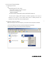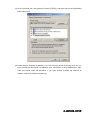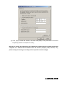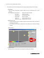
1
User Manual
FX8 Range-Finding Sensor
LA9532A
Version 2.0
MEMS Promotion Department
Visionary Business Center
Nippon Signal Co., Ltd.
Nippon Signal Co., Ltd.
A -LA9532ALA9532A- 001E
001E
Contents
1. Precautions Before Using this Product ...................................................................................3
2. Configuration & Specifications.................................................................................................7
2.1 Configuration & internal function blocks ............................................................................7
2.2 Equipment specifications ...................................................................................................9
2.2.1 Environmental conditions ..............................................................................................9
2.2.2 Power supply (recommended) ......................................................................................9
2.2.3 External cables & connectors........................................................................................9
2.2.4 External dimensions & weight .....................................................................................10
2.2.5 Sensor installation specifications ................................................................................10
2.3 Distance measurement specifications.............................................................................11
2.4 Data communication specifications .................................................................................12
3. Main unit & accessories ........................................................................................................13
4. How to use the FX8 special software....................................................................................14
4.1 Operating environment ....................................................................................................14
4.2 Setting the computer’s IP address...................................................................................14
4.3 How to use the sample display software .........................................................................17
4.4 How to use the FX8 setup software.................................................................................20
4.5 Format of data saved using the display software ............................................................22
Inquiries .....................................................................................................................................25
Approved by
Checked by
4
2
2
0
1
1
Prepared by
A -LA9532ALA9532A- 002E
002E
1. Precautions Before Using this Product
In order to use this product effectively, before using it, please be sure to read all matters relating
to the products you have purchased.
This User Manual contains information that is important when using this product. Please retain it
so that you can refer to it when necessary.
Safety Precautions
A number of symbols have been used in this User Manual to assist you in using this product
safely and correctly, and to prevent injury to people or damage to property. The symbols and
their meanings are as follows. Please familiarize yourself with them fully before reading the rest
of this User Manual.
This indicates that if this symbol is ignored and the product is
Warning handled incorrectly, there is the potential risk of someone
suffering a serious injury.
This indicates that if this symbol is ignored and the product is
Caution
handled incorrectly, there is the potential risk of someone
suffering a serious injury, and the potential for only property to be
damaged.
Examples of symbols used
Signifies that there is something requiring caution (including warnings).
Indicates that care needs to be taken.
Signifies that some action is prohibited.
Indicates that something must not be done.
Signifies that some action is to be compelled or instructed.
Indicates that something must be done.
A -LA9532ALA9532A- 003E
003E
Warning
◆ Do not look through the glass window on the laser emission surface for a long
period of time while the sensor is operating. Doing so may injure your eyes.
◆ Do not use the product at a supply voltage other than the voltage prescribed.
Doing so may cause fire or an electric shock.
◆ In the unlikely event something unusual occurs, such as smoke or a foul
smell coming from the product, shut off the power supply immediately.
◆ In the unlikely event smoke has been coming from the product, check that the
smoke has stopped, and request that the product be serviced. Due to the
danger, you should never attempt to repair the product yourself.
A -LA9532ALA9532A- 004E
004E
Caution
◆ Vibrations and impacts
Do not subject the product to strong vibration or shock, such as by dropping it.
If this product has been dropped onto the floor, the product cannot be
guaranteed.
Precise optical elements have been used in this product. Any mechanical
vibration, impact or so forth may damage the product and result in
performance degradation.
Take care when handling the glass window as it is particularly fragile.
◆ Environmental conditions
Take care not to leave the product in an area where there are condensation
or corrosive gases.
Certain environmental conditions may cause performance degradation.
◆ Wiring
If this product has not been used correctly, such as incorrect wiring, incorrect
insertion of a connector or used in excess of the rated range of use, the
product may not perform properly or it may be rendered ineffective.
◆ Disassembly
If this product is taken apart, users may be injured as a result of performance
degradation, broken internal components or other such reasons.
Also, the product cannot be guaranteed once it has been taken apart.
◆ Instructions for washing/cleaning
If normal properties cannot be attained due to the glass window on the laser
emission surface becoming dirty, dip a cotton swab, gauze or some other
clean, soft cloth into a tiny amount of reagent ethanol (ethyl alcohol) and
lightly wipe away the dirt.
Do not wash any other parts besides the glass window.
◆ This User Manual and the documents, electronic data, programs and other
attachments included with the product are prohibited from being reproduced,
transcribed, distributed, altered, etc., either in part or in full, without
A -LA9532ALA9532A- 005E
005E
authorization from our company.
◆ Imitating this product or otherwise producing similar products is prohibited.
◆ Please note that the contents of this User Manual are subject to change
without notice.
A -LA9532ALA9532A- 006E
006E
2. Configuration & Specifications
2.1 Configuration & internal function blocks
Figure 2.1 shows the configuration and internal function blocks of the sensor.
Sensor
Ranging data
Data transfer
block
Communications
Internal power
supply block
12V DC supply
cable
Control processing
block
Computer
Projector-receiver
block 図3.1 機器構成
Laser beams
Sensor
Measured
object
Internal function block
Item prepared by user
Figure 2.1 Configuration and internal function blocks
(1) Projector-receiver block
The projector-receiver block projects a laser toward the measured object via an ECO SCAN®
mirror, which scans two-dimensionally at high speed. It then receives reflected/diffused light
irradiated by the measured object located along the optical path.
(2) Control processing block
The control processing block measures the time lag between the timing of the laser beam being
projected and the timing of the reflected/diffused light being received from the measured object,
and converts this time lag into distance. This block also controls the 2D scanning and ranging
by using the 2D scanning control by ECO SCAN® and generating a laser output timing signal
that is synchronized with this.
(3) Data transfer block
The data transfer block transfers the ranging data and light quantity data from the control
processing block to the computer.
A -LA9532ALA9532A- 007E
007E
(4) Internal power supply block
The internal power supply block produces the required voltage for each block using the
externally provided input power supply.
A -LA9532ALA9532A- 008E
008E
2.2 Equipment specifications
2.2.1 Environmental conditions
[The performance of items under development is currently being assessed. This product
should be used at normal temperature, normal humidity and in an indoor environment.]
(1) Operating temperature and humidity:
-10°C to +50°C, 20-85%RH (However, maximum absolute humidity of 36g/m3)
(2) Storage temperature and humidity:
-30°C to +70°C, 20-100%RH (However, maximum absolute humidity of 36g/m3)
(3) Vibrations & impacts:
In XYZ directions, 10-500Hz, 1G (double amplitude); 40Hz, 2G (double amplitude)
In XYZ directions, 30G (impact)
(4) Dustproof & waterproof: equivalent to IP55
(5) Sunlight resistance:
able to find the range of a whiteboard 1m away at 100,000lx
2.2.2 Power supply (recommended)
DC +12V ±2V
Minimum 2.0A (Maximum steady current consumption of 0.5A)
2.2.3 External cables & connectors
(1) Power cable
Connector: round crimp terminal (RBV0.3-3YE)
Length: 1.5m
(2) Communications cable
Connector: RJ45 plug (male)
Length: 1.5m
Power supply terminal
Power cable
Sensor
Red:
White:
Green:
Yellow:
+12V
GND
FG
for maintenance
(do not connect)
Communications
cable
Communications
terminal
Figure 2.2 external cables
A -LA9532ALA9532A- 009E
009E
2.2.4 External dimensions & weight
(1) External dimensions
W60×D90×H65mm (see Figure 2.3)
(2) Mass
Approximately 500g
2.2.5 Sensor installation specifications
Nuts used for mounting when installing sensor:
8 × 5mm-deep M3 tap (4 each on top and bottom surface)
Install the product in a way that the vent on the underside for preventing condensation
does not become blocked by a bracket, etc., and so that, wherever practicable, the
product does not get splashed with water, etc.
(tap for installation)
Vent 23-NTF210SE
Vent 23-NTF210SE
Figure 2.3 Sensor installation specifications
A -LA9532ALA9532A- 010E
010E
2.3 Distance measurement specifications
Item
Specifications
Method of measuring
Optical pulse “time of flight” (TOF)
Frame rate / number of
measuring points*1
*1
Format label
A
B
C
D
Frame rate / pixels
20fps±2fps / 1075 pixels (43 × 25)
16fps±1.6fps / 1749 pixels (53 × 33)
10fps±1fps / 2535 pixels (65 × 39)
4fps±0.4fps / 5917 pixels (97 × 61)
Scanning viewing angle
Horizontal 60° × Vertical 50°
Accuracy of scanning
angle
Horizontal 60°±1. 0°, Vertical 50°±1. 0°
Distance range*2
0.3-5.0m (Munsell scale N4.0, equivalent to reflectance of 12%)
* Up to maximum of 15m is possible depending on the reflectance of the
measured object
Accuracy of distance*2
Maximum of ±5cm (@±3σ)
(Munsell scale N4.0, reflectance 12%,
distance 5m, Ta: repeatability at 25°C)
Range resolution
10mm (system resolution)
Laser safety standard
Class 1 (IEC60825-1: 2001) near-infrared pulse laser
Status display
Displayed using indicator lamps
See LX9638A Communications Interface Specifications V1.1 (P8-4.3.3)
The frame rate / number of pixels able to be used by each sensor is indicated according to the
ABCD marking (○) on the format label on the rear of the main unit. Dual mode sensors have
markings in two places.
*2
The distance range and accuracy may not be guaranteed depending on the conditions of the
measured object (reflectance and slope) and the environmental conditions. [Specifications not
yet achieved for items under development]
A -LA9532ALA9532A- 011E
011E
2.4 Data communication specifications
Item
Specifications
Communication standard
(Physical / data-link layer)
Ethernet 10Base-T/100Base-TX
(auto-negotiation enabled)
Communication protocol
(Network / transport layer)
Control commands / ranging data: TCP/IP
IP address
Factory default IP address: 192.168.0.80
(can be changed using FX8 setup software)
MDI/MDI-X
Auto MDI/MDI-X compatible
Data output
[Ranging data] For each measuring point: distance value (12bit),
light value (12bit)
See LX9638A Communications Interface Specifications V1.1
A -LA9532ALA9532A- 012E
012E
3. Main unit & accessories
(1) Main sensor unit (including communications cable and power cable)
(2) Accompanying CD
The folder structure and contents for the accompanying CD are as follows:
• User Manual
• Communications Interface Specifications
• User Library Specifications
• .NET Framework Runtime Package
• FX8 Setup Software
• Sample Display Software
• User Library Package
• Project Package for C++/CLI Sample Software
Compatible version: Microsoft Visual C++ 2005 or later
• Project Package for Visual Basic .NET Sample Software
Compatible version: Microsoft Visual Basic 2005 or later
A -LA9532ALA9532A- 013E
013E
☆
4. How to use the FX8 special software
4.1 Operating environment
OS
Microsoft Windows XP or later version
Microsoft.NET Framework 2.0 SP2 is required
(included on accompanying CD)
Method of installation
Run files in the order: [NetFx20SP2_x86.exe], [NetFx20SP2_x86ja.exe].
The files used in installing .NET Framework are different depending on the version of
Windows you are using. For more details, please read the “Installing dotnet.txt” file
contained in the “dotnet” folder of the accompanying CD.
☆
4.2 Setting the computer’s IP address
Before connecting the sensor and computer, you will need to set the computer’s IP address.
(1) From the Windows Control Panel, (double) click [Network Connections].
(2) Right-click [Local Area Connection] and click on [Properties].
A -LA9532ALA9532A- 014E
014E
(3) On the [General] tab, click [Internet Protocol (TCP/IP)], and then click on the [Properties]
button below that.
(4) Select [Use the following IP address]. If you are using the sensor for the first time, or if you
have not changed the sensor’s IP address, enter 192.168.0.1 in the IP address box. Also,
make the subnet mask 255.255.255.0. If you have already changed the sensor’s IP
address, enter an IP address accordingly.
A -LA9532ALA9532A- 015E
015E
(5) Click [OK] to close the window, and then click [OK] in the [Local Area Connection
Properties] window to complete the setting.
Note: If you change the settings for the IP address as outlined above, and then connect the
computer to a network that is different from the sensor (company LAN, internet, etc.),
please change the settings according to the respective network settings.
A -LA9532ALA9532A- 016E
016E
4.3 How to use the sample display software
This software can be used to display and record ranging images and light volume images.
(1) Installation
Copy the entire [/FX8_display software/] folder from the accompanying CD to your
computer.
[File configuration] bw_table.dat:
display black and white table
Clr_scl.dat:
display color table
fx8clientlib.dll:
communication library
fx8userlib.dll:
library for display
fx8disp.exe:
display software main unit
fx8disp.exe.config:
display software setup file
(2) Directions for use
• Connect the sensor and your computer using the communications cable, and switch on
the power to the sensor.
• In the folder you have copied, double-click the file [fx8disp.exe] to startup the display
software.
[Startup screen]
☆
3
1
4
2
5
① Sensor Connect
[Connect]: Connect to the sensor to be displayed by entering its IP address.
A -LA9532ALA9532A- 017E
017E
② Sensor Control
[Start]: Commence range-finding using the connected sensor.
Due to the scanning synchronization/adjustment, it may take a little time for the
screen to display.
[File Save]: By ticking this box, the ranging data will be saved in the same folder as the
program.
③ Ranging image display area:
This area displays the ranging image. You can check the distance using the color bar at
the bottom of the screen.
To change the scope of the color bar, using Notepad or some other text editor, change the
values of the [fx8disp.exe.config] file in the folder.
<add key="DispRange0" value="0.0" /> Value=“**.*” display minimum distance (m), red
<add key="DispRange1" value="10.0" /> Value=“**.*” display maximum distance (m), blue
④ Light volume image display area:
This area displays an image representing the values of the volume of light received. You
can check the light value using the black-and-white bar at the bottom of the screen.
⑤ Information tab
Displays various information about the connected sensor.
⑥ Option tab
Select the sensor’s frame rate (ranging mode). (Dual mode sensors only)
Setting: 0 = low frame rate, 1 = high frame rate
(Example: In case of 4FR and 16FR: 0 = 4FR, 1 = 16FR)
☆
6
A -LA9532ALA9532A- 018E
018E
⑦ Indicator tab
Here, you can change how the status indicators on the main unit switch on or flash.
(The sample software settings will return to the factory default settings if the power to the
main unit is switched off.)
☆
7
[Keep]: Maintain the value set for the sensor.
[Default]: Return to the factory default setting.
[ON]: Permanently switched on
[OFF]: Permanently switched off
[TimeSet]: Set any interval between ON and OFF while flashing.
(1-100, 100msec units. Example: 1 = 0.1sec, 100 = 10sec)
⑧ Replay tab
Replays the ranging data saved on the computer.
[ReplayMode]: Ticking this box switches to the replay mode for saved data. If connected to
the sensor, the connection will be cut.
[ReplayFile]: Sets the path for the file to be replayed.
[FileCutout]: Outputs the data between the set frames to a new file.
[Interval]: Duration between frames
☆
8
A -LA9532ALA9532A- 019E
019E
⑨ ErrorInfo tab
Displays information on any errors that have occurred on the sensor.
☆
9
4.4 How to use the FX8 setup software
This software can be used to set the IP address of the sensor and to switch the operating
mode (frame rate / number of measuring points).
(1) Installation
Copy the [fx8conftool.exe] file from the [FX8_setup software] folder on the accompanying
CD to your computer.
(2) Directions for use
• Connect the sensor and your computer using the communications cable, and switch on
the power to the sensor.
• Double-click the [fx8conftool.exe] file to start it.
[Startup screen]
☆
1
From (1), select the specifications for the sensor you want to change the settings for, enter
the appropriate data, and click [Start setup].
* Normally, select the [IP address specification].
A -LA9532ALA9532A- 020E
020E
[Setup screen]
☆
[Sensor Setting]: Acquires the setup information for the sensor, and displays a list.
[IP Address]:
By entering an arbitrary IP address and clicking [Set], the IP address will be
recorded to flash memory, and the sensor’s IP address will be changed
when the power is turned on again.
[DHCP Client]:
By ticking the [Enable] box and clicking [Set], the sensor will switch to the
mode of automatically acquiring IP addresses. (The power needs to be
turned back on for an IP address to be automatically acquired.)
[Measure Mode]: Set the frame rate for when the sensor’s power is turned on. (Dual mode
sensors only)
The set value is recorded to flash memory, and will become the initial value
when the power is turned on.
Setting: 0 = low frame rate, 1 = high frame rate
(Example: In case of 4FR and 16FR: 0 = 4FR, 1 = 16FR)
A -LA9532ALA9532A- 021E
021E
4.5 Format of data saved using the display software
Filename: Shows the time that data acquisition commenced.
last two digits of the year+month+date+_(underscore)+hour+minute+second.fx8
(Example: 100921_101135.fx8)
Data configuration: Binary data comprised of a header section, XY data section, and a ranging data
section
Header
section
XY data section
Plane 0
(Plane 1)
…
(Plane N-1)
Ranging data section
1st frame
2nd frame
…
Mth frame
[Header section]
Offset
0
1
2
3
4
5
6
7
8
9
10
11
12
13-43
44
45
46
47
48
49
50
51
52
53
54
55
56
57
58
59
60
61
62
63
Data content
X number of measuring points
(upper 8bit)
X number of measuring points
(lower 8bit)
Y number of measuring points
(upper 8bit)
Y number of measuring points
(lower 8bit)
X deflection angle (upper 8bit)
X deflection angle (lower 8bit)
Y deflection angle (upper 8bit)
Y deflection angle (lower 8bit)
Number of planes of XY data
Frame period (upper)
Frame period (lower)
Ranging mode
Upper limit of ranging mode
Spare
XY data management number (1)
XY data management number (2)
XY data management number (3)
XY data management number (4)
Logic version (major)
“ (minor)
“ (sequence)
“ (spare)
Frame version (major)
“ (minor)
“ (sequence)
“ (spare)
Sensor serial number (leftmost
character)
“ (2nd character)
“ (3rd character)
“ (4th character)
“ (5th character)
“ (6th character)
“ (7th character)
“ (8th character)
Notes
Half-angle 0.1 degree (ex. ±30° = 300)
Half-angle 0.1 degree (ex. ±25° = 250)
N planes
Millisecond units
(used for reproduction interval, etc.)
0/1
0 to 1
0x00 fixed
ASCII code (space 0x20)
A -LA9532ALA9532A- 022E
022E
☆
64
65
66
67
68-255
Save software version (major)
“
(minor)
“
(sequence)
“
(spare)
Spare
0x00 fixed
[XY data section]
Offset
0
1
2
3
4
Data content
X coordinate
Y coordinate
1st
Sx (upper)
measuring
Sx (lower)
point
Sy (upper)
5
...
(P-1)*6+0
(P-1)*6+1
(P-1)*6+2
(P-1)*6+3
(P-1)*6+4
(P-1)*6+5
Sy (lower)
...
Pth
measuring
point
Notes
0 - X number of measuring points -1
0 - Y number of measuring points -1
for conversion of XYZ coordinates
Binary values (Sx,Sy): values 0 – 20,000
The value calculated by subtracting 10,000 and
dividing by 10,000 becomes the coefficient.
(→ -1.000 – 0 – +1.000)
...
X coordinate
Y coordinate
Sx (upper)
Sx (lower)
Sy (upper)
Sy (lower)
Measuring point number: P (= 1 – X number of measuring points × Y number of measuring points)
Saves data for the number of planes of XY data (Header section offset = 12).
[Ranging data section] (in case of ranging data)
Offset
Data content
0
0xF0
For verifying
1
0xF0
synchronization 0xF0
2
3
0xF0
4
Upper
Frame number
5
Lower
6
Data type
0x71
7
Plane number
8
Year
9
Month
10
Date
Time stamp
(PC clock)
11
Hour
12
Minute
13
Second
14-77
Internal sensor information
Light volume
78
(upper)
Light volume
79
1st measuring
(lower)
point
Range
80
(upper)
Range
81
(lower)
...
...
Pth measuring Light volume
(P-1)*4+78
point
(upper)
Notes
Number issued sequentially by sensor (also
including error notifications)
Plane number for referenced XY data
Last two digits of the year (ex. 2010 = 0x0A)
(0x01 – 0x0C)
(0x01 – 0x1F)
24-hour basis (0x00 – 0x17)
(0x00 – 0x3B)
(0x00 – 0x3B)
A -LA9532ALA9532A- 023E
023E
(P-1)*4+79
(P-1)*4+80
(P-1)*4+81
Light volume
(lower)
Range
(upper)
Range
(lower)
Measuring point number: P (= 1 – X number of measuring points × Y number of measuring points)
[Ranging data section] (in case of error notification)
Offset
0
1
2
3
4
5
6
7
8
9
10
11
12
13
14-77
78
79
80
81
82
83
84
85
86+
Data content
Notes
0xF0
For verifying
0xF0
synchronization 0xF0
0xF0
Upper
Number issued sequentially by sensor (also
Frame number
including ranging data)
Lower
Data type
0x91
Spare
0x00
Year
Last two digits of the year (ex. 2010 = 0x0A)
Month
(0x01 – 0x0C)
Date
(0x01 – 0x1F)
Time stamp
(PC clock)
Hour
24-hour basis (0x00 – 0x17)
Minute
(0x00 – 0x3B)
Second
(0x00 – 0x3B)
Internal sensor information
Sensor status
Upper
Sensor status
Lower
Error code
(0)
Error code
(1)
Error code
(2)
Error code
(3)
Error code
(4)
Error code
(5)
Fill in 0x00 so that it ends up the same size as for the ranging data
A -LA9532ALA9532A- 024E
024E
Inquiries
MEMS Promotion Department, Visionary Business Center, Nippon Signal Co., Ltd.
13F Shin-Marunouchi Building, 1-5-1 Marunouchi, Chiyoda-ku, Tokyo 100-6513, Japan
TEL +81-3-3217-7167
FAX +81-3-3217-7377
Copyright © 2010 NIPPON SIGNAL CO., LTD. All Rights Reserved.
○
A -LA9532ALA9532A- 025E
025E