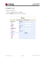
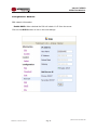
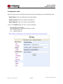
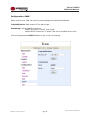
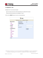
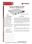
1
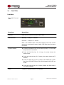
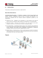
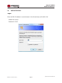
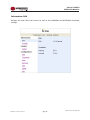
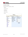
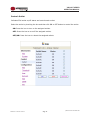
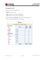
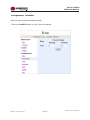
OPERATING MANUAL AC POWER DISTRIBUTION UNITS VIGILANT SERIES www.unipowerco.com Manual No. PDUAC1USM-2 pduac1us-man-rev2-0115.indd © 2015 UNIPOWER LLC All Rights Reserved NORTH AMERICA • 3900 Coral Ridge Drive, Coral Springs, Florida 33065, USA • Tel: +1 954-346-2442 • Fax: +1 954-340-7901 • [email protected] EUROPE • Parkland Business Centre, Chartwell Road, Lancing BN15 8UE, ENGLAND • Tel: +44(0)1903 768200 • Fax: +44(0)1903 764540 • [email protected] VIGILANT SERIES OPERATING MANUAL Contents 1.0INTRODUCTION................................................................................................................4 2.0 PDU PACKAGE...................................................................................................................5 3.0FUNCTION..........................................................................................................................6 4.0INSTALLATION..................................................................................................................8 5.0 WEB INTERFACE.............................................................................................................10 Manual No. PDUAC1USM-2 Page 2 pduac1us-man-rev2-0115.indd VIGILANT SERIES OPERATING MANUAL OPERATING MANUAL 1. Introduction 1.0 VIGILANT SERIES VIGILANT SERIES OPERATING MANUAL INTRODUCTION The VIGILANT Series is a family of Internet ready Power Distribution Units (PDU) designed and is equipped with an intelligent current-meter (True RMS) that will indicate the total power consumption of the connected loads. These PDUs offer easy to set up user-friendly communication software which provides the functions to assist network manager in remotely monitoring multiple PDU power consumption for the entire enterprise. Features: Built-in web server, the network manager can monitor the current consumption of the PDU in real time. Build-in true RMS current meter. Easy setup, the meter can display the IP address directly. Homepage supports SSL. Provides an audible alarm when power consumption is in excess of preset warning and overload limits. Can send emails and SNMP Alarm Traps when the power consumption exceeds the above limits. The supplied software utility can monitor a large number of PDUs at the same time. SNMP support with provided MIB allows for the PDU to be monitored by a NMS. Real time to control of individual outlets. LED outlets status indication. Power on sequencing. Manual No. PDUAC1USM-2 VIGILANT Series PDU User Manual Page 3 Page 4 pduac1us-man-rev2-0115.indd 10/10 pduac1us-man VIGILANT SERIES VIGILANT SERIES OPERATING MANUAL OPERATING MANUAL 2. PDU Package 2.0 PDU PACKAGE The standard package contains a VIGILANT Series PDU with supporting hardware and software. The components of the package are: Power Distribution Unit. Rack mount Brackets. CD-ROM containing: User Manual. PDU Software. MIB: Management Information Base for Network. (PDUMIB.mib) Adobe Acrobat Reader. VIGILANT Series PDU User Manual Manual No. PDUAC1USM-2 Page 5 Page 4 10/10 pduac1us-man pduac1us-man-rev2-0115.indd VIGILANT SERIES VIGILANT SERIES OPERATING MANUAL OPERATING MANUAL 3. Function 3.0 FUNCTION Interface True RMS Current Meter Functions Description Ethernet RJ45 port for network communication port. Audible Alarm Warning - 1 beep in 1 second. Overload - 3 beeps in 1 second. Note: The audible alarm will keep beeping until the current returns to normal and is also at least 0.5A lower than the alarm threshold. Function Button Press and release to turn off the warning beep. The overload beep cannot be cancelled. Press and hold the key for 1 beep; the meter shows the total current. Press and hold the key for 2 beeps; the meter shows the IP address Press and hold the key for 4 beeps; sets DHCP ON or OFF. Note that VIGILANT Series PDUs are shipped with DHCP set to ON. Press and hold the key for 6 beeps; Resets the PDU back to it’s default settings. Meter 3 digits to display current or IP Address. VIGILANT Series PDU User Manual Manual No. PDUAC1USM-2 Page 6 Page 5 10/10 pduac1us-man pduac1us-man-rev2-0115.indd VIGILANT SERIES OPERATING VIGILANT SERIES MANUAL OPERATING MANUAL LED Indicator SSL (yellow): Light on means web access is protected by SSL. DHCP (Green): Light on means the PDU gets its IP address through DHCP. A - H (Green): Indicates the status of each outlet. Circuit Breaker Manual No. PDUAC1USM-2 Overload power protection. Push to reset. VIGILANT Series PDU User Manual Page 6 Page 7 pduac1us-man-rev2-0115.indd 10/10 pduac1us-man VIGILANT SERIES OPERATING MANUAL VIGILANT SERIES OPERATING MANUAL 4. Installation 4.0 INSTALLATION This section provides quick instructions to install the PDU. Rack Mount Instructions A) Elevated Operating Ambient - If installed in a closed or multi-unit rack assembly, the operating ambient temperature of the rack environment may be greater than room ambient. Therefore, consideration should be given to installing the equipment in an environment compatible with the maximum ambient temperature specified by the manufacturer. B) Reduced Air Flow - Installation of the equipment in a rack should be such that the amount of air flow required for safe operation of the equipment is not compromised. C) Mechanical Loading - Mounting of the equipment in the rack should be such that a hazardous condition is not achieved due to uneven mechanical loading. D) Circuit Overloading - Consideration should be given to the connection of the equipment to the supply circuit and the effect that overloading of the circuits might have on over current protection and supply wiring. Appropriate consideration of equipment nameplate ratings should be used when addressing this concern. E) Reliable Earthing - Reliable earthing of rack-mounted equipment should be maintained. Particular attention should be given to supply connections other than direct connections to the branch circuit (e.g. use of power strips). Diagram VIGILANT Series PDU User Manual Manual No. PDUAC1USM-2 Page 8 Page 7 10/10 pduac1us-man pduac1us-man-rev2-0115.indd VIGILANT SERIES OPERATING MANUAL VIGILANT SERIES OPERATING MANUAL Hardware 1. Install mounting brackets. The PDU comes with brackets for mounting in a rack. To mount the PDU into a rack perform the following procedure: Attach the mounting brackets to the unit, using the four retaining screws provided for each of the brackets. Choose a location for the brackets. Align the mounting holes of brackets with the notched hole on the vertical rail and attach with the retaining screws. 2. Connect input and output power. 3. Connect Ethernet cable to the PDU. 4. Switch on the PDU. Note 1: The default setting for obtaining an IP address is via DHCP. If a DHCP server is not available the IP address can be programmed as desired manually using a PC set to the same network segment and connected with a cross-over Ethernet cable. The default IP address is 192.168.0.216. Note 2: TO SETUP THE NETWORK SYSTEM FOR VIGILANT PDUs, IT IS STRONGLY RECOMMENDED TO BUILD UP THE POWER MONITORING NETWORK ISOLATED FROM ANY OTHERS. Manual No. PDUAC1USM-2 VIGILANT Series PDU User Manual Page 8 Page 9 pduac1us-man-rev2-0115.indd 10/10 pduac1us-man VIGILANT SERIES VIGILANT SERIES OPERATING MANUAL OPERATING MANUAL 5. Web Interface 5.0 WEB INTERFACE Login: Enter the PDU IP address in a web browser in the format http://192.168.0.216 Default ID is snmp. Password is 1234. VIGILANT Series PDU User Manual Manual No. PDUAC1USM-2 Page 10 Page 9 10/10 pduac1us-man pduac1us-man-rev2-0115.indd VIGILANT VIGILANT SERIES SERIES OPERATING OPERATING MANUALMANUAL Information: PDU Displays the total PDU load current as well as the WARNING and OVERLOAD threshold settings. VIGILANT Series PDU User Manual Manual No. PDUAC1USM-2 Page 11 Page 10 10/10 pduac1us-man pduac1us-man-rev2-0115.indd VIGILANT VIGILANT SERIES SERIES OPERATING MANUAL OPERATING MANUAL Information: System Indicates PDU system information, including: Model No. Firmware Version MAC Address System Name System Contact Location VIGILANT Series PDU User Manual Manual No. PDUAC1USM-2 Page 12 Page 11 10/10 pduac1us-man pduac1us-man-rev2-0115.indd VIGILANT VIGILANT SERIES SERIES OPERATING OPERATING MANUAL MANUAL Control: Outlet Indicates PDU outlet on/off status and controls each outlet. Select the outlet by checking the box and then click ON or OFF button to control the outlet. ON: Press the icon to turn on the assigned outlets. OFF: Press the icon to turn off the assigned outlets. OFF/ON: Press the icon to reboot the assigned outlets. VIGILANT Series PDU User Manual Manual No. PDUAC1USM-2 Page 13 Page 12 10/10 pduac1us-man pduac1us-man-rev2-0115.indd VIGILANT VIGILANT SERIES SERIES OPERATING OPERATING MANUALMANUAL Configuration: PDU Sets the outlet name and delay time. Name: Rename the outlet. ON: Set delay time for power on sequencing. OFF: Set delay time for power off sequencing. Click on the appropriate APPLY button to lock in the new settings. Note: The maximum delay time is 255 seconds. VIGILANT Series PDU User Manual Manual No. PDUAC1USM-2 Page 14 Page 13 10/10 pduac1us-man pduac1us-man-rev2-0115.indd VIGILANT VIGILANT SERIES SERIES OPERATING OPERATING MANUALMANUAL Configuration: Threshold Sets the warning and overload threshold. Click on the APPLY button to lock in the new settings. VIGILANT Series PDU User Manual Manual No. PDUAC1USM-2 Page 15 Page 14 10/10 pduac1us-man pduac1us-man-rev2-0115.indd VIGILANTVIGILANT SERIES SERIES OPERATING OPERATING MANUALMANUAL Configuration: User Change ID and password. Default ID is snmp and password is 1234. Click on the APPLY button to lock in the new settings. VIGILANT Series PDU User Manual Manual No. PDUAC1USM-2 Page 16 Page 15 10/10 pduac1us-man pduac1us-man-rev2-0115.indd VIGILANT VIGILANT SERIES SERIES OPERATING OPERATING MANUALMANUAL Configuration: Network PDU network information Enable DHCP: When checked the PDU will obtain it’s IP from the server. Click on the APPLY button to lock in the new settings. VIGILANT Series PDU User Manual Manual No. PDUAC1USM-2 Page 17 Page 16 10/10 pduac1us-man pduac1us-man-rev2-0115.indd VIGILANT VIGILANT SERIES SERIES OPERATING OPERATING MANUALMANUAL Configuration: Mail When an event occurs, the PDU can send out an email message to a pre-defined account. Email Server: Enter the Mail Server’s Domain Name. Sender’s Email: Enter the sender email address. Email Address: Enter the recipient email address. Click on the APPLY button to lock in the new settings. The message in the email: Indicates OutletA~H-XXXXXXXX status in order X=0 : means power off. X=1 : means power on. Note: Make sure DNS server can resolve the Email Server’s domain name. VIGILANT Series PDU User Manual Manual No. PDUAC1USM-2 Page 18 Page 17 10/10 pduac1us-man pduac1us-man-rev2-0115.indd VIGILANT VIGILANT SERIES SERIES OPERATING OPERATING MANUAL MANUAL Configuration: SNMP When event occurs, PDU can send out trap message to pre-defined IP address. Trap Notification: Sets receiver IP for alarm traps. Community: Sets the SNMP community. Read Community is “public” and “fixed”. Default Write Community is “public” and can be modified by the user. Click on the appropriate APPLY button to lock in the new settings. VIGILANT Series PDU User Manual Manual No. PDUAC1USM-2 Page 19 Page 18 10/10 pduac1us-man pduac1us-man-rev2-0115.indd VIGILANTVIGILANT SERIES SERIES OPERATING OPERATING MANUALMANUAL Configuration: SSL Enables SSL for web communication. User must enter the correct ID and password to enable SSL function. These must be the same as the settings in “User”. Click on the APPLY button to lock in the new settings. This document is believed to be correct at time of publication and UNIPOWER LLC accepts no responsibility for consequences from printing errors or inaccuracies. Specifications are subject to change without notice. VIGILANT Series PDU User Manual Page 20 10/10 pduac1us-man Manual No. PDUAC1USM-2 Page 19 pduac1us-man-rev2-0115.indd