1
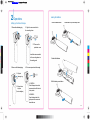
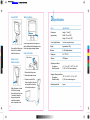
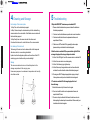
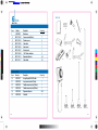
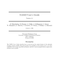
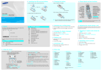
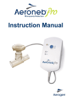
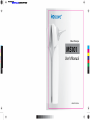
User Manual
-.
20130314 -24page .ai 1 2013/5/17 T 午 04:42:57
Video Otoscope
C
M
MS101
Y
CM
MY
User’s Manual
CY
CMY
K
UM-AP1005-08-A
User Manual
-.
20130314 -24page .ai
2 2013/5/17 T 午 04:43:00
®
Thank you for choosing the MDSCOPE Video Otoscope, the
Video Otoscope choice for health care professionals. The
operating and maintenance instructions found in this manual
should be followed to ensure product reliability. Please read this
manual carefully before using the product.
If you experience a technical problem related to operation of the
®
MDSCOPE Video Otoscope, please contact your local dealer for
the after-sales support. You may also contact the customer
service at +886 2 2999-5505 or [email protected]
C
M
FDA listed:
V
D083901, D119968, D150295
CM
IEC 60601-1, IEC 60601-1-2
MV
CV
CMV
When there is a need to immediately report an adverse effect in connection
with operation of the MDSCOPE® Video Otoscope, please contact the
K
authorized representative or the agent. You may also contact the customer
service at +886 2 2999-5505 or [email protected]
U.S. Agent:
Harvest Consulting Corp.
Medical Device Safety Service GmbH
2904 N, Boldt Drive, Flagstaff
Schiffgraben 41, 30175 Hannover
Arizona 86001, U.S.A.
Germany
The manufacturer declares on his/her sole
responsibility that the product is in conformity
with the essential requirements of the 93/42/EEC
Medical Device Directive, and that the relevant
conformity assessment procedures have been
fulfilled.
©2012 by Apple Biomedical, Inc. All Rights reserved. Reproduction or reprinting
of any part of this manual by any means without written authorization from
Apple Biomedical Inc. is strictly prohibited. Printed in Taiwan.
01
User Manual
-.
20130314 -24page .ai
3 2013/5/17 T 午 04:43:00
Contents
1 Introduction
Chapter 1 Introduction ................................................ 03
The MDSCOPE Video Otoscope is a hand-held medical device that
includes a video camera for capturing a video image of the outer ear
canal and/or tympanic membrane. The image is displayed directly on a
built-in screen or displayed on an external display device via connec®
tion to a video out port. The MDSCOPE video otoscope is preset for
its focus, brightness level and white balance. It is powered by two AA
batteries for a continuous operation of about 4 hours.
Features ...................................................... 04
Symbols ........................................................ 05
Saftey and Cautions .................................... 06
Use of Long/Flexible Camera Module .......... 07
Chapter 2 Operations.............................................................08
C
Setting up the Otoscope ............................... 08
M
Loading the Batteries ................................... 09
V
Power ON / OFF ........................................... 10
Batteries Condition ..................................... 10
Image Freeze / Release Function .............. 10
Video Out Function ..................................... 10
CM
MV
CV
®
Video imaging provides several advantages over direct visualization.
®
The MDSCOPE video otoscope may be operated with an image
dongle to record the otoscopic images which are used to create
®
medical history for each patient. By using the MDSCOPE video
otoscope, health professionals can review and discuss the clinical
findings with patients to enhance the doctor/patient interaction.
CMV
Chapter 3 Specifications ............................................ 11
K
Chapter 4 Cleaning and Storage ................................ 12
Chapter 5 Troubleshooting ........................................ 13
Chapter 6 Parts .......................................................... 14
Chapter 7 Limited Warranty ........................................16
Appendix EMC Guidance and Manufacturer’s declaration
(Tables 201, 202, 204, 206) ........................17
02
Intended use
®
The MDSCOPE video otoscope is as an assistive tool to observe the
health condition of the ear. Indications for use include: Inspection of the
outer ear canal and tympanic membrane, and detection of hearing aid
devices.
The device may also be coupled a flexible camera module to monitor
the health condition of the mouth. Indications for use include inspection
of palate, tongue and anterior of oropharynx.
®
The MDSCOPE video otoscope should not be used for
any other purposes.
03
User Manual
-.
20130314 -24page .ai
4 2013/5/17 T 午 04:43:01
Symbols
MS101 features
Safety Symbols
Screen
Camera
module
Power indicator
Fastening
Ring
Manufacturer
Serial number
Caution
Not protected against the ingress of water
+49°C
ON/OFF button
C
-20°C
M
Image Freeze
button ____
V
Release
button
Type BF
Temperature limits
Symbol for "AUTHORIZED
REPRESENTATIVE IN THE
EUROPEAN COMMUNITY"
CE mark has been identified according
to Article 17 of the MDD(93/42/EEC )
CM
Battery
Cover
MV
CV
CMV
K
Consult instructions for use
video out port
Button Symbols
Power
04
Press
Video out
05
User Manual
-.
20130314 -24page .ai
5 2013/5/17 T 午 04:43:01
Saftey and Cautions
®
The MDSCOPE video otoscope should be operated under supervision
of a trained ENT doctor or health professionals with sufficient knowledge of otoscopy.
*Under an extreme laboratory test condition at 40°C, the applied
part of the device may be measured at a temperature of no higher
than 60°C and its enclosure at 49°C if it is turned on continuously
for more than 2 hours.
*Do not use this device in the presence of
inflammable anesthetics.
*Please follow local rules and regulations regarding
disposal or recycling of the device and its components.
Suggested Use of Long/Flexible Camera module
(For User purchasing the long/flexible camera modules)
*The Video signal output (RCA Port) connector is intended for
C
connection to devices that comply with IEC 60601-1, or other IEC
The long camera module is selected when it is difficult to get near to
M
standards (for example, IEC 60950), as appropriate to the device.
the target using the standard camera module. As the MDSCOPE®
V
*Do not apply alcohol, chemicals, or water to clean the lenses.
Solution entering the optical assembly can cause short-circuits
CM
for electrical components.
MV
*Portable and mobile wireless communications device which
CV
CMV
K
video otoscope is operated with the long camera module, the user
needs to ensure that the tip of the camera module is held a distance
NOT less than 1cm away from the target in the ear canal.
The flexible camera module is selected when it is difficult to get near to
transmits radiofrequency (RF) may affect the performance of
the target using the long camera module. As the MDSCOPE® video
the medical electrical device.
otoscope is operated with the flexible camera module, the user needs
*Please remove the batteries if the device is stored for a long time.
to ensure that the tip of the camera module is held a distance NOT less
than 1cm away from the target in the oral cavity.
*Some patients may feel warm and uncomfortable at the probe
during the diagnosis when the device is left switched ON for a
long period of time. The operator of the device should first
discuss the possible discomfort with the patient, and when
necessary withdraw the device from the patient and switch it off
until the probe no longer feels warm.
WARNING: No modification of this equipment is allowed.
06
07
User Manual
-.
20130314 -24page .ai
6 2013/5/17 T 午 04:43:01
2 Operations
Loading the Batteries
Setting up the Video Otoscope
1. Push the release button.
1. Remove the fastening ring.
2. Slide down to open the battery cover.
2. Align the camera module to
the mounting base.
2.1 Remove the
protective cover.
C
M
Insert the camera module
V
to the mounting base via
the mating parts
CM
MV
3. Load in the batteries.
CV
3. Screw on the fastening ring.
CMV
4. Put on new speculum before using.
K
3.1 Align the
fastening ring.
3.2 Screw it down
to tighten.
(Do not overtighten)
4.1 CAPPING:
Push the flanged end onto the
camera module until it clicks into
a lock position.
4.Put the battery cover back on.
4.2 REMOVE :
Press the flanged end of the
rigid speculum to remove and
discard after use.
08
09
User Manual
-.
20130314 -24page .ai
7 2013/5/17 T 午 04:43:02
Power ON/OFF
C
Press and hold the power
button for 2 seconds to
switch the device on.
M
V
CM
Image Freeze /
Release Function
MV
Battery Conditions
When the light switches from green to
red, it indicates that the batteries are low.
In this case, please change batteries.
Video Out Function
“Video out” port
CV
CMV
K
1. Remove the battery cover.
2. Remove the video out cover.
When the power is turned
ON, Press the image
freeze button for less than
1 second to freeze the
image, and press the
same button again to
return to preview mode.
10
4. Connect one end of the
video out cable to the video
out port and the other end
to the monitor video port
3 Specifications
Item
Specifications
Dimensions
(approximate)
Length : 7.5 cm (3")
Width : 6.3 cm (2-1/2")
Height : 21.2 cm (8-3/8")
Focal length/distance
1 to 4 cm away from target
Weight
Approximately 180 g
Batteries
2 x AA Alkaline batteries
Display size
2.4" TFT LCD
Video out
NTSC system
Operating conditions
Temperature
Relative humidity
+10° C to +40° C (+50° F to +104°
F) 30% to 75% non-condensing
Shipping / Storage conditions
Temperature
Relative humidity
Predicted product life
-20° C to +49° C (-4° F to +120°
F) 95% non-condensing max
2 years
11
User Manual
-.
20130314 -24page .ai
8 2013/5/17 T 午 04:43:02
4 Cleaning and Storage
5 Troubleshooting
For cleaning of the camera probe
1. Why is the MDSCOPE video otoscope not switched ON?
1st Step: Take out the alcoholized prep-pad.
2nd Step: Clean and wipe the stainless steel part of the standard/long
camera module or the outer sheath of the flexible camera module with
the alcoholized prep-pad.
3rd Step: Gently clean the camera lens with the cotton swab.
Care should be taken not to scratch the lens of the camera module.
For cleaning of the main unit
The housing of the main unit can be cleaned with a cloth dampened
with water, alcohol, or a non-staining disinfectant.
Liquids should not be dripped or spilled over the surfaces of the LCD
module, pogo pins or handle as they are not watertight.
C
M
V
CM
MV
Storage
The camera module and main unit should be placed in the
storage compartment of the carrying case.
Unnecessary exposure to extremes in temperature and humidity
should be avoided.
CV
CMV
K
®
1. Please confirm the batteries have power and reload the batteries in
the battery compartment.
2. Check and confirm the batteries are positioned in correct orientation.
3. Check and confirm the button can be depressed with ease, and
repeat at least 10 times.
4. If the device is NOT switched ON by repeating the above steps,
please contact your local dealer for technical supports.
2. After the device is switched ON, the power indicator light is ON but
no image is displayed or the image is fuzzy and unstable.
1. Confirm if the LED light in front of the camera module is switched ON.
2. Confirm if camera module is mounted properly.
3. Confirm if the fastening ring is tightened up.
4. Confirm if there is any foreign substance stuck on the metal contact
and clean the surface of metal contact with alcoholized prep-pad.
5. If the image is still NOT displayed properly after carrying out steps 14 above, please contact your local dealer for technical supports.
3. The device is switched ON with image displayed but I can’t
freeze the image.
1. Restart the device and try the freeze function again.
2. Check and confirm the button can be depressed with ease, and
repeat at least 10 times.
12
3. The main unit may be defective if the freeze function does not work
after repeating the above steps for several times. Please contact your
local dealer for technical supports.
13
User Manual
-.
20130314 -24page .ai
9 2013/5/17 T 午 04:43:03
6 Parts
Parts List
Basic Parts
W arranty
card
5
C
M
V
Item
1
2
3
4
5
6
7
8
9
Number
MS101-001
MS101-002
MS101-003
MS101-005
MS101-006
MS101-007
MS101-008
MS101-016
MS101-017
Description
Main device
Camera module (45mm)
Protective cover
Video cable
User manual
Warranty card
“AA” Alkaline batteries
Disposable Specula
Cotton Swab
Quantity
Description
Image Dongle With USB cable
Long camear module (75mm)
Flexible camera module (150mm)
Flexible camera module (300mm)
Disposable Specula
Cable Set
Quantity
1
1
1
1
250
1
1
1
2
1
1
1
2
24
25
6
8
7
4
10
9
3
14
15
CM
MV
CV
Optional Parts
CMV
K
Item
10
11
12
13
14
15
Number
MS101-011
MS101-012
MS101-013
MS101-014
MS101-015
MS101-018
2
11
12
13
1
14
15
User Manual
-.
20130314 -24page .ai 10 2013/5/17 T 午 04:43:03
7 Limited Warranty
®
Each of the MDSCOPE video otoscope comes with a one-year
warranty, starting on the purchase date to cover repair and/or if
necessary replacement of any product failure due to defects in
materials and workmanship. Within the limited range of the warranty,
defective products shall be repaired or replaced by the Manufacturer
or authorized technical and service groups at their options and to the
extent permitted by law.
Appendix
Table 201
Guidance and manufacture's declaration-electomagnetic emissions
®
The MDSCOPE video otoscope is intended for use in the electromagnetic environment specified below. The customer or the users of the
device should assure that it is used in the such an environment.
Emissions test
Compliance
Electromagnetic environment - guidance
RF emissions CISPR11
Group 1
The device uses RF energy only for its internal
function. Therefore, its RF emissions are very
This warranty is non transferable. Damages due to negligence,
accident, abuse, misapplication, modification, or repairs not made by
the Manufacturer, or authorized technical and service groups, are not
covered by the warranty. Within the coverage of the warranty, the
delivery fee for mailing to the local dealer or the direct store is not
covered within the scope of the warranty.
C
M
V
CM
MV
low and are not likely to cause any interference
in nearby electronic equipment.
The device is suitable for use in all establishRF emissions CISPR11
Class B
ments, including domestic establishments
and those directly to the public low-voltage
power supply network that supplies building
CV
used for domestic purposes.
CMV
K
16
EU Representative:
Medical Device Safety Service
GmbH Schiffgraben 41, 30175
Hannover Germany
Harmonic emissions
IEC 61000-3-2
Not Applicable
Manufacturer:
APPLE BioMedical Inc.
8th Floor, No.12, Lane 609, Chong Shin Road Sec.5, New Taipei,
24159, Taiwan.
Voltage fluctuations/
flicker emissions
IEC 61000-3-3
Not Applicable
17
User Manual
-.
20130314 -24page .ai 11 2013/5/17 T 午 04:43:03
Table 202
Guidance and manufacture's declaration-electomagnetic immunity
Table 204
Guidance and manufacture's declaration-electomagnetic immunity
The MDSCOPE® video otoscope is intended for use in the electromagnetic environment specified below. The customer or the user of the device
should assure that it is such an environment.
The MDSCOPE® video otoscope is intended for use in the electromagnetic environment specified below. The customer or the user of the device
should assure that it is such an environment.
Immunity test
Electrostatic
discharge
(ESD)
IEC
61000-4-2
C
M
V
CM
MV
CV
CMV
K
IEC 60601
test level
± 6 kV contact
± 8 kV air
Compliance
level
± 6 kV
contac
t
± 8 kV air
Electrical fast ± 2 kV for power
transient /bursts supply lines
IEC 61000-4-4
± 1 kV for
input/output lines
Not
Applicable
Surge
IEC
61000-4-5
±1 kV line(s) to line(s)
Not
Applicable
Voltage dips,
short
interruptions
and voltage
variations on
power supply
input lines
IEC 61000-411
< 5 % UT (>95 % dip Not
in UT) for 0,5 cycle
Applicable
Power
frequency
magnetic field
IEC 61000-48
3 A/m
±2 kV line(s) to earth
Electromagnetic environment guidance
Portable and mobile RF communications
equipment should be used no closer to any
part of the device, including cables, than the
recommended separation distance calculated
from the equation applicable to the frequency
of the transmitter.
Recommended separation
distance d=1,2√P
Radiated RF 3 V/m
IEC61000-4-3 80 MHz to 2,5
GHz
3 V/m
d =1,2√P 80MHz to 800 MHz
d =2,3√P 800 MHz to 2,5 GHz
where P is the maximum output power rating of
the transmitter in watt (W) according to the
transmitter manufacturer and d is the
recommended separation distance in meters(m).
Field strength from fixed RF transmitters, as
determined by an electromagnetic site survey,
a
should be less than the compliance level in
each frequency rangeb .
Interference may occur in the vicinity of
equipment marked with the following symbol:
40 % UT (60% dip in
UT) for 5 cycle s
70 % UT (30% dip in
UT) for 25 cycles
< 5 % UT (>95 % dip
in UT) for 5 s
0,3 A/m
IEC 60601 Complianc Electromagnetic environment - guidance
test level
e level
Conducted RF 3 Vrms
Not
IEC61000-4-6
150 kHz to 80 Applicable
MHz
Floors should be of wood, concrete or
ceramic tiles. If the floor is tiled with
synthetic material the relative air
humidity must have 30 % at least.
If image distortion occurs, it may be
necessary to position the device image
intensifier further from sources of power
frequency magnetic fields or to install
magnetic shielding. The power frequency
magnetic field should be measured in the
intended installation location to assure
that it is sufficiently low.
NOTE : UT is the a.c. mains voltage prior to application of test level.
18
Immunity test
NOTE 1: At 80 Hz and 800 MHz, the higher frequency range applies.
NOTE 2: These guidelines may not apply in all situations. Electromagnetic propagation is
affected by absorptions and reflections from structures, objects and people.
Field strength from transmitters such as base stations for radio (celluar/cordes) telephones and
mobile radio, amateur radio, AM and FM radio and TV broadcast cannot be predicted
theoretically with accuracy. To assess the electromagnetic environment due to fixed RF
transmitters, an electromagnetic site survey should be considered. If the measured field strength
in the location in which the device is used exceeds the applicable RF compliance above, the
device should be observed to verify normal operation. If abnormal performance is observed,
additional measures may be necessary, such as re-orienting or relocating the device.
a
b
Over the frequency range 150 kHz to 80 MHz, field strength should be less than 3 V/m.
19
User Manual
-.
20130314 -24page .ai 12 2013/5/17 T 午 04:43:03
Table 206
Recommended separation distances between portable and mobile RF
communications equipment and the MDSCOPE® Video Otoscope
The device is intended for use in an electromagnetic environment in
which radiated RF disturbances are controlled. The user of the device
can help prevent electromagnetic interference by maintaining a minimum
distance between portable and mobile RF communication equipment
(transmitters) and the device as recommended below, according to the
maximum output power of the communications equipment.
Rated maximum
output power of
transmitter
W
C
Separation distance according to the frequency of transmitter
m
150 kHz to 80 MHz
d=1,2√P
150 kHz to 80 MHz 150 kHz to 80 MHz
d=1,2√P
d=1,2√P
M
0,01
0,12
0,12
0,23
V
0,1
0,38
0,38
0,73
1
1,2
1,2
2,3
10
3,8
3,8
7,3
100
12
12
23
CM
MV
CV
CMV
For transmitters rated at a maximum output power not listed above, the recommended
separation distance d in the meters (m) can be estimated using the equation applicable to the
frequency of the transmitter, where P is the maximum output power rating of the transmitter in
watts (W) according to the transmitter manufacture.
K
NOTE 1: At 80 Hz and 800 MHz the separation distance for the frequency range applies.
NOTE 2: These guidelines may not apply in all situations. Electromagnetic propagation is
affected by absorptions and reflections from structures, objects and people.
20