1
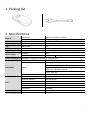
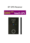
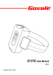
G2P User Manual v1.0 Copyright © 2014 Gosafe LEGAL NOTICE Copyright © 2014 Gosafe. All rights reserved. Reproduction, transfer, distribution or storage of part or all of the contents in this document in any form without the prior written permission of Gosafe is prohibited. Other products and company names mentioned herein may be trademarks or trade names of their respective owners. SAFETY Using connectors, ports, and buttons Never force a connector into a port or apply excessive pressure to a button, because this may cause damage that is not covered under the warranty. If the connector and port don’t join with reasonable ease, they probably don’t match. Check for obstructions and make sure that the connector matches the port and that you have positioned the connector correctly in relation to the port. Operating temperature G2P is designed to work in ambient temperatures between and stored in temperatures between -20℃ to +50℃. G2P can be damaged and battery life shortened if stored or operated outside of these temperature ranges. Avoid exposing G2P to dramatic changes in temperature or humidity. When you’re using G2P or charging the battery, it is normal for G2P to get warm. Explosive atmospheres Do not charge or use G2P in any area with a potentially explosive atmosphere, such as a fueling area, or in areas where the air contains chemicals or particles (such as grain, dust, or metal powders). Obey all signs and instructions. Radio frequency interference Observe signs and notices that prohibit or restrict the use of mobile phones (for example, in healthcare facilities or blasting areas). Although G2P is designed, tested, and manufactured to comply with regulations governing radio frequency emissions, such emissions from G2P can negatively affect the operation of other electronic equipment, causing them to malfunction. Turn off G2P or use Airplane Mode to turn off the G2P wireless transmitters when use is prohibited, such as while traveling in aircraft, or when asked to do so by authorities. Charging Charge G2P with the included USB cable, or with other third-party cables and power adapters that are compatible with USB 2.0, or power adapters compliant with one or more of the following standards: EN 301489-34, IEC 62684, YD/T 1591-2009, CNS 15285, ITU L.1000, or another applicable mobile phone power adapter interoperability standard. Contents 1. Packing list..................................................................................................................................................................... 1 2. Specifications ................................................................................................................................................................ 1 3. Features and event ....................................................................................................................................................... 2 3.1. Features ................................................................................................................................................................. 2 3.2. Supported event list ............................................................................................................................................... 2 4. Overview ....................................................................................................................................................................... 3 4.1. Front ....................................................................................................................................................................... 3 4.2. Rear ........................................................................................................................................................................ 3 5. Getting started .............................................................................................................................................................. 4 5.1. Install SIM card ....................................................................................................................................................... 4 5.2. Set up by SMS command ....................................................................................................................................... 4 6. LED behavior ................................................................................................................................................................. 5 7. User command .............................................................................................................................................................. 6 1.Command UNO0 ........................................................................................................................................................ 6 2.Command UPW0 ........................................................................................................................................................ 6 3.Command USP0;0 ...................................................................................................................................................... 6 4.Command USP0;1 ...................................................................................................................................................... 6 5.Command UNO1 ........................................................................................................................................................ 7 6.Command UPW1 ........................................................................................................................................................ 7 7.Command USP1;0 ...................................................................................................................................................... 7 8.Command USP1;1 ...................................................................................................................................................... 8 9.Command MEI............................................................................................................................................................ 8 10.Command PRQ ......................................................................................................................................................... 8 11.Command TZN ......................................................................................................................................................... 9 12.Command DNU ........................................................................................................................................................ 9 13.Command APN ......................................................................................................................................................... 9 14.Command SVR.......................................................................................................................................................... 9 15.Command SVP;0..................................................................................................................................................... 10 16.Command SVP;1..................................................................................................................................................... 10 17.Command SOS........................................................................................................................................................ 10 18.Command BMC ...................................................................................................................................................... 11 19.Command GFS........................................................................................................................................................ 11 20.Command PSS ........................................................................................................................................................ 11 21.Command LED ........................................................................................................................................................ 12 22.Command MGR ...................................................................................................................................................... 12 23.Command CID ........................................................................................................................................................ 12 8. Message sample .......................................................................................................................................................... 13 1. Packing list 2. Specifications Physical Environment Bluetooth USB CPU LED indicator Power supply Dimension Weight Operating temperature NOT Supported Micro USB ARM 1 LED indicators External Lithium battery 66.5(L)*35.5(W)*12.5(H)mm N/A -20℃ to +50℃ (with backup battery) N/A 2.0 SC6531 GSM & GPS & POWER N/A Type Rechargeable, Li-Po 3.7V, 600mAh Power consumption Standby: [email protected], Operating: [email protected] Antenna GSM/GPRS GPS Sensor Flash storage Model SIM card Internal antenna External antenna Model Channel Accuracy Sensitivity Acceleration sensor 16Mbits Built-In SPREADTRUM SC6531 Quad band: 850/900/1800/1900MHz Multiple-slot Class 8 (dual band)/10 (quad band) GPRS class 10/Station class B TCP/IP over PPP 1.8V & 3.3V, Micro SIM FPC Not supported u-Blox G7020 50 Parallel Channels Autonomous<2.5M -162dBm Built-In, 3 axis Built-In 1 3. Features and event 3.1. Features SOS button to trigger instant SOS message Daily life water proof standard A-GPS supported Private activity hour mode Circular Geo fence supported Dynamic report interval on preset conditions Replaceable battery Mobile application & PC configuration utility Fall down detection 3.2. Supported event list Tracker is capable to report below specific events instantly via GPRS/SMS channel as peer setting. # 1. 2. 3. 4. 5. 6. 7. 8. 9. Event name SOS button pressed Battery low voltage GPS unfix to fix GPS fix to unfix Entering grey area Leaving grey area Entering Geo-fence Leaving Geo-fence Fall down To user cell To GPRS host server 2 4. Overview 4.1. Front SOS event button Pressing over 1 second to trigger SOS event LED indicator Please refer chapter 6 Micro USB interface For charging battery & PC configuration utility 4.2. Rear Power switch Pressing over 2 seconds to power ON/OFF G2P Battery cover Remove battery cover by flipping it from this crack 3 5. Getting started 5.1. Install SIM card Remove cover at the shown direction from here. 1 2 Flip up battery from here to find the SIM card holder. 3 Step1: Release SIM holder at shown direction. Step2: Insert SIM card to SIM holder, Metal part of SIM card facing to PCB board. Step3: Lock SIM card holder at shown direction. Step4: Align contact point to install battery back. 5.2. Set up by SMS command Please refer chapter 7 “User command”. 4 6. LED behavior LED behavior is determined by command LED, by default (LED;300;10) it will acting as below, please refer command LED in chapter 7 for further information. 5 7. User command 1.Command UNO0 This command is to set user phone number#1 that has authority to interact with tracker. Example: Phone number: 13800138000, country code: +86 1234,UNO0;+8613800138000 Tracker User SMS G2P V1.00 UNO0:+8613800138000 BAT 60% #1 2.Command UPW0 This command is to change the default password 1234 for user phone number#1, 4 digits fixed. 1234,UPW0;5678 Tracker User SMS G2P V1.00 UPW0:5678 EXT_PWR=11.94V BAT 60% #2 3.Command USP0;0 This command is to set report mode0 for user phone number#1 1234,USP0;0;30S;G;W Tracker Remark User SMS G2P V1.00 USP0;0;<Report interval>;<Paramter1>;<Paramter2> USP0:0;30S;G;W BAT 60% <Report interval>: #1 Range is from 30S to 900S, 15M to 59M, 1H to 720H. S = Second M = Minute H = Hour <Parameter1>: G = GPS position preferred. O = Disable position report. <Parameter2>: T = Position is shown in text. W = Position is shown is hyper link. Note: O is letter. 4.Command USP0;1 This command is to set report mode1 for user phone number#1 1234,USP0;1;30M;G;W Tracker Remark User SMS G2P V1.00 USP0;1;<Report interval>;<Paramter1>;<Paramter2> USP0:1;30M;G;W 6 BAT 60% #1 <Report interval>: Range is from 30S to 900S, 15M to 59M, 1H to 720H. S = Second M = Minute H = Hour <Parameter1>: G = GPS position preferred. O = Disable position report. <Parameter2>: T = Position is shown in text. W = Position is shown is hyper link. Note: O is letter. 5.Command UNO1 This command is to set user phone number#2 that has authority to interact with tracker. Example: Phone number: 13800138000, country code: +86 1234,UNO1;+8613800138000 Tracker User SMS G2P V1.00 UNO1:+8613800138000 BAT 60% #1 6.Command UPW1 This command is to change the default password 1234 for user phone number#2, 4 digits fixed. 1234,UPW1;5678 Tracker User SMS G2P V1.00 UPW1:5678 BAT 60% #2 7.Command USP1;0 This command is to set report mode0 for user phone number#2 1234,USP1;0;30S;G;W Tracker Remark User SMS G2P V1.00 USP1;0;<Report interval>;<Paramter1>;<Paramter2> USP1:0;30S;G;W BAT 60% <Report interval>: #1 Range is from 30S to 900S, 15M to 59M, 1H to 720H. S = Second M = Minute H = Hour <Parameter1>: G = GPS position preferred. 7 O = Disable position report. <Parameter2>: T = Position is shown in text. W = Position is shown is hyper link. Note: O is letter. 8.Command USP1;1 This command is to set report mode1 for user phone number#2 1234,USP1;1;30M;G;W Tracker Remark User SMS G2P V1.00 USP1;1;<Report interval>;<Paramter1>;<Paramter2> USP1:1;30M;G;W BAT 60% <Report interval>: #1 Range is from 30S to 900S, 15M to 59M, 1H to 720H. S = Second M = Minute H = Hour <Parameter1>: G = GPS position preferred. O = Disable position report. <Parameter2>: T = Position is shown in text. W = Position is shown is hyper link. Note: O is letter. 9.Command MEI This command is to query GSM module IMEI of tracker, aka device ID. 1234,MEI Tracker User SMS G2P V1.00 MEI:351535053999389 BAT 60% #3 10.Command PRQ This command is to query current position of tracker. 1234,PRQ Tracker User SMS G2P V1.00 LTM 2013-06-06 14:17:12 http://maps.google.com/maps?q=23.164374,113.428576&t=m&z=16 SPD 0km/h 0 CSQ -52dBm BAT 60% #5 Note: Position information in message may vary depending on setting/current status. 8 11.Command TZN This command is to set local time. 1234,TZN;08:00 Tracker User SMS G2P V1.00 TZN:08:00 BAT 60% #6 Remark TZN;<Time zone> <Time zone>: Format is HH;MM, range from -13:00 to 13:00. 12.Command DNU This command is to set switching condition for report mode0 and report mode1. 1234,DUN;3 Tracker Remark User SMS G2P V1.00 DNU;<Parameter> DNU:3 BAT 60% <Parameter>: #6 0 = Always stick with mode0. 1 = When roaming switch to mode1, otherwise stick with mode0. 2 = When battery low switch to mode1, otherwise stick with mode0. 3 = Either roaming or battery low will switch to mode1, otherwise stick with mode0. 13.Command APN This command is to set necessary information to connect with GPRS network. 1234,APN;CMNET;123;456 Tracker Remark User SMS G2P V1.00 APN;<APN name>;<Username>;<Password> APN:CMNET;123;456 BAT 60% #6 14.Command SVR This command is to set GPRS host server IP and port 1234,SVR; 76.74.174.164;3032;;0 Tracker User SMS G2P V1.00 SVR:76.74.174.164;3032;;0 BAT 60% #6 Remark SVR;<IP>;<TCP port>;<UDP port>;<Mode> <IP>: Host server IP or domain name. <TCP port>: Available TCP port <UDP port>: Available UDP port <Mode>: 0 = Using TCP protocol 1 = Using UDP protocol 9 15.Command SVP;0 This command is to set report mode0 to GPRS host server. 1234,SVP;0;30S;G;T Tracker Remark User SMS G2P V1.00 SVP;0;<Report interval>;<Paramter1>;<Paramter2> SVP:0;30S;G;T BAT 60% <Report interval>: #1 Range is from 30S to 900S, 15M to 59M, 1H to 720H. S = Second M = Minute H = Hour <Parameter1>: G = GPS position preferred. O = Disable position report. A = GPS and LBS position. <Parameter2>: T = Position is shown in text. 16.Command SVP;1 This command is to set report mode0 to GPRS host server. 1234,SVP;1;30M;G;T Tracker Remark User SMS G2P V1.00 SVP;1;<Report interval>;<Paramter1>;<Paramter2> SVP:1;30M;G;T BAT 60% <Report interval>: #1 Range is from 30S to 900S, 15M to 59M, 1H to 720H. S = Second M = Minute H = Hour <Parameter1>: G = GPS position preferred. O = Disable position report. A = GPS and LBS position. <Parameter2>: T = Position is shown in text. 17.Command SOS This command is to toggle SOS button pressed event. 1234,SOS;1 Tracker Remark User SMS G2P V1.00 SOS;<Parameter> SOS:1 BAT 60% <Parameter>: #6 0 = Disable SOS button. 1 = Enable SOS button. 10 18.Command BMC This command is to set threshold percentage for battery low event. 1234,BMC;30 Tracker Remark User SMS G2P V1.00 BMC;<Percentage> BMC:30 BAT 60% <Percentage>: #6 Low than this value will switch to low voltage status and trigger battery low event, range is from 5 to 99. 19.Command GFS This command is to define a Geo fence. 1234,GFS;1;25.31;113.0;1000 Tracker User SMS G2P V1.00 GFS:1;25.31;113.0;1000 BAT 60% #1 Remark GFS;<Toggle>;<Latitude>;<Longitude>;<Radius> <Toggle>: 0 = Disable Geo-fence. 1 = Enable Geo-fence. <Latitude>: Latitude of centre point of circular Geo fence, In degree. <Longitude>: Longitude of centre point of circular Geo fence, in degree <Radius>: Unit is meter, range from 100 to 1000000. 20.Command PSS This command is to toggle power saving mode. 1234,PSS;1;3;2 Tracker Remark User SMS G2P V1.00 PSS;<Toggle>;<Stop duration>;<Transmission idle duration> PSS:1;3;2 BAT 60% <Toggle>: #6 0 = Disable power saving mode. 1 = Enable power saving mode. <Stop duration>: Device stops for such duration will switch to power saving mode, unit is minute, range from 1 to 255. <Transmission idle duration> Device has not data transmission request for such duration will switch to power saving mode, unit is minute, range from 1 to 255. 11 Default: PSS;1;3;2 21.Command LED This command is to set LED behavior. 1234,LED;300;10 Tracker Remark User SMS G2P V1.00 LED;<Power saving>;<Cycle interval> LED:300;10 BAT 60% <Power saving>: #6 Value can be 0, and integer between 60 to 65535, unit is second. 0 = Disable LED power saving mode, LED behavior always stick with chapter 6. 60 to 65535 = Any value between will enable LED power saving mode. If battery is under “Normal” status, after power on G2P LED will only work for such duration and stop working (power saving purpose), until battery is under “Charging/Charged/Low voltage” status LED will work again as chapter 6 shown. <Cycle interval>: This value defines interval between each LED cycle, default is 10 seconds. E.g.: Command BMC set as BMC;60, command LED set as LED;300;10, and current battery is 70% full, operating on battery only. So since power ON, at the first 5 minutes LED will work as chapter 6 and then stop working, afterwards battery drops under 60% (or connect with charger) LED will start working as Chapter 6 shown again. Note: If any LED status changes then the <cycle interval> will be forced as 5 seconds for one time. 22.Command MGR This command is to check current accumulation mileage of tracker, unit is meter. 1234,MGR Tracker User SMS G2P V1.00 MGR:100000 BAT 60% #6 23.Command CID This command is to check CCID of tracker SIM card. 1234,CID Tracker User SMS G2P V1.00 CID:89860090191149028638 BAT=3.90V #7 12 8. Message sample Content of message G2P V1.00 LTM 2013-06-06 14:17:12 http://maps.google.com/maps?q=%n(,%e&t=m&z=16 SPD:0km/h 0 GSM -52dBm BAT 60% #30 Explanation Device name/Firmware version Date/Time Google map hyper link Speed/Heading GSM network signal strength Built-in battery voltage Consumed messages Content of message G2P V1.00 LTM 2013-06-06 09:41:22 GPS 1.55/0.50/3/4 N23.164302 E113.428456 SPD:0km/h 0 GSM -52dBm BAT 60% #27 Explanation Device name/Firmware version Date/Time HDOP/ALTITUDE in meter/Fixed satellite number/Time of first fixed N means north/S means south E means east/W means west Speed/Heading GSM signal strength Built-in battery voltage Consumed messages Content of message G2P V1.00 LTM 2013-02-28 23:51:09 MCC/MNC/LAC/CID/RSSI 460/0/2503/962C/-53dBm 460/0/2731/40F4/-60dBm 460/0/2703/4050/-70dBm GSM -58dB BAT 60% #20 Explanation Device name/Firmware version Date/Time Base station information type Main station, MNC/MNC/Local area code/Station ID/Signal strength Neighbor station 1 Neighbor station 2 GSM network signal strength Built-in battery voltage Consumed messages Content of message G2P V1.00 LTM 2013-06-06 14:17:12 http://maps.google.com/maps?q=%n(,%e&t=m&z=16 ETD:0/SOS GSM -52dBm BAT 60% #301 Explanation Device name/Firmware version Date/Time Google map hyper link Event ID/User defined event name GSM network signal strength Built-in battery voltage Consumed messages 13