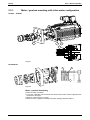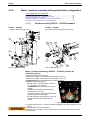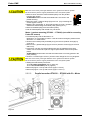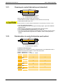
1
Electromechanical Automation ETH - Electro Cylinder Mounting instructions ETH Manual - Installation, Commissioning, Maintenance and Repair ETH - Electro Cylinder Parker High Force Electro Thrust Cylinder 192-550002 192-550002N6 ETH Mounting Instructions Novemer 2015 We reserve the right to make technical changes. The data correspond to the current status at the time of printing. 28.10.15 15:21 192-550002N6 ETH Mounting Instructions 2015-11 Introduction ETH - Electro Cylinder ____________________________ Production site: Parker Hannifin Manufacturing Germany GmbH & Co. KG Electromechanical Automation Europe [EME] Robert-Bosch-Strasse 22 77656 Offenburg (Germany) Tel.: + 49 (0781) 509-0 Fax: + 49 (0781) 509-98176 Internet: www.parker.com/eme http://www.parker.com/eme E-mail: [email protected] mailto:[email protected] Parker Hannifin GmbH - registered office: Bielefeld HRB 35489 Management Board: Ellen Raahede Secher, Dr.-Ing. Hans-Jürgen Haas, Günter Schrank, Kees Veraart - Chairman of the board: Hansgeorg Greuner Italy: Parker Hannifin Manufacturing Srl Electromechanical Automation Europe [EME] Via C. Gounod, 1 20092 Cinisello Balsamo (Milano), Italy Tel.: + 39 (0)2 361081 Fax: + 39 (0)2 36108400 Internet: www.parker.com/eme http://www.parker.com/eme E-mail: [email protected] mailto:[email protected] Non-warranty clause We checked the contents of this publication for compliance with the associated hard and software. We can, however, not exclude discrepancies and do therefore not accept any liability for the exact compliance. The information in this publication is regularly checked, necessary corrections will be part of the subsequent publications. German Master created. Further information: Our product on the internet: http://www.parker.com/eme/eth About this manual This manual contains notes and safety instructions, information about commissioning, service and maintenance. For information on project development (technical data, dimensions, accessories, options, dimensioning aids and order code) please refer to ETH catalogue (www.parker.com/eme/eth see product support of one ETH side). 2 192-550002N6 ETH Mounting Instructions 2015-11 Device assignment Parker EME Contents 1. Introduction .............................................................................................5 1.1 1.2 1.3 1.4 Device assignment .................................................................................. 5 Type specification plate .......................................................................... 5 Mounting explanation .............................................................................. 6 Intended use ............................................................................................. 7 1.4.1. 1.5 Safety instructions ................................................................................... 7 1.5.1. 1.5.2. 1.5.3. 1.5.4. 1.5.5. 1.6 General hazards ................................................................................................. 7 Identifying Residual Dangers and Hazardous Areas ..................................... 7 Working safely ................................................................................................... 8 Safety Instructions for the Company Using the System ............................... 8 Safety Instructions for Operating Personnel .................................................. 9 Packaging, storage, transport .............................................................. 10 1.6.1. 1.7 1.8 Applications not in accordance with the intended use ................................. 7 Special notes on transport ............................................................................. 10 Terms of guarantee / warranty .............................................................. 14 Conditions of utilization ........................................................................ 15 2. Set-up .....................................................................................................17 2.1 Mounting ................................................................................................. 17 2.1.1. 2.1.2. 2.1.3. 2.2 Electric installation ................................................................................ 22 2.2.1. 2.2.2. 2.2.3. 2.3 Mounting with mounting threads on the cylinder ........................................ 17 Mounting with mounting accessories ........................................................... 17 2.1.2.1 Cylinder mounting with mounting plates or foot mounting brackets ..... 18 2.1.2.2 Screw tightening torques for the mounting of the ETH cylinder by the customer ......................................................................................... 18 2.1.2.3 Accessory mounting - bearing block ..................................................... 20 2.1.2.4 Mounting of force sensors..................................................................... 20 2.1.2.5 Mounting - Fixing of accessories - Rear clevis with force sensor ......... 20 Mounting notes ................................................................................................ 21 2.1.3.1 Side Load .............................................................................................. 21 2.1.3.2 Mounting of the payload........................................................................ 21 Direction of the motor during extension of the cylinder ............................. 22 Sensors ............................................................................................................. 22 2.2.2.1 Sensor mounting ................................................................................... 23 Setting the end limits ...................................................................................... 23 Motor and feedback mounting .............................................................. 25 2.3.1. 2.3.2. 2.3.3. Motor / gearbox mounting with inline motor configuration ........................ 26 Motor / gearbox mounting with parallel motor configuration ..................... 28 2.3.2.1 Parallel mounting ETH032 ... ETH080 Standard .................................. 28 2.3.2.2 Parallel mounting ETH032 ... ETH080 with Ex - Motor ........................ 29 2.3.2.3 Parallel mounting ETH100 & ETH125 .................................................. 31 2.3.2.4 Re-apply toothed belt pre-tension (reinsert the same toothed belt) ..... 33 2.3.2.5 Resetting the toothed belt pre-tension (new toothed belt) .................... 33 IP65 motor mount ............................................................................................ 34 2.3.3.1 Motor mounting for IP65 inline .............................................................. 34 2.3.3.2 IP65 motor mount parallel ..................................................................... 35 3. Maintenance and service ......................................................................36 3.1 Maintenance schedule ........................................................................... 36 192-550002N6 ETH Mounting Instructions 2015-11 3 Introduction 3.2 Lubricating intervals and amount of lubricant .................................... 37 3.2.1. 3.2.2. 3.3 Greasing via central lubrication port (standard) .......................................... 38 Relubrication via central lubrication port (option) ....................................... 38 Toothed belt ........................................................................................... 39 3.3.1. 3.3.2. 3.3.3. 3.4 ETH - Electro Cylinder Checking the toothed belt............................................................................... 39 Exchanging the toothed belt (ETH032 ... 080)............................................... 40 Exchanging the toothed belt (ETH100&125) ................................................. 41 Belt / belt tensions ................................................................................. 42 4. Repair .....................................................................................................42 5. Index.......................................................................................................43 4 192-550002N6 ETH Mounting Instructions 2015-11 Device assignment Parker EME 1. Introduction In this chapter you can read about: Device assignment ............................................................................................................5 Type specification plate ..................................................................................................... 5 Mounting explanation.........................................................................................................6 Intended use......................................................................................................................7 Safety instructions .............................................................................................................7 Packaging, storage, transport .......................................................................................... 10 Terms of guarantee / warranty ......................................................................................... 14 Conditions of utilization .................................................................................................... 15 1.1 Device assignment This manual is valid for the following devices: Electro cylinder for motors and gearboxes: ETH032 ETH050 ETH080 ETH100 ETH125 1.2 Type specification plate Type specification plate (example) Type specification plate explanation Left: Right: Manufacturer address Serial number Type: Order confirmation No.: Date: 192-550002N6 ETH Mounting Instructions 2015-11 Unambiguous identification number Order Code Customer Order Number Delivery date 5 Introduction 1.3 6 ETH - Electro Cylinder Mounting explanation 192-550002N6 ETH Mounting Instructions 2015-11 Intended use Parker EME 1.4 Intended use The incomplete machine can only be set in operation if it is sure that the machine in which the incomplete machine shall be mounted is conform to the 2006/42/EG machine directives. Without further measures the product is not suitable for safety-oriented tasks. The linear motor module must only be used in areas that are not accessible to persons during operation. If the linear actuator is used in areas accessible to people, it must be installed in such a manner that no one can be endangered during operation. The described safety, installation and operating instructions must be adhered to. The general functioning mode consists in converting a rotational movement in a linear movement without slip within the product related load limits according to the information in the catalogue. Its applications are in industry and trade. The linear actuator has a number of uses including: Positioning, transporting, feeding, removing, pallet handling, loading, unloading, processing and manipulating as well as testing work pieces or tools. Since the component can be used in a very wide range of applications, the user is responsible for its use in specific applications. 1.4.1. Applications not in accordance with the intended use For risks of applications not in accordance with the intended use the user shall bear the sole responsibility. Parker Hannifin does not accept any liability for damages caused by applications not in accordance with the intended use of the product. 1.5 1.5.1. Safety instructions General hazards General Hazards on Non-Compliance with the Safety Instructions The subsystem has been designed in accordance with state-of-the-art technical developments and is operationally reliable. If it is not operated by qualified or at least trained personnel or if it is operated improperly or not in accordance with the operating instructions, however, the unit may bear the risk of hazards. Electronic, moving and rotating components can represent a danger for life and limb of the operator or third persons and / or cause material damage . If the linear actuator is installed in a machine plant, the safety requirements noted in the operating instructions for that machine must be combined with those described in this manual. 1.5.2. Identifying Residual Dangers and Hazardous Areas If there are still residual dangers present to persons or property from the linear actuator in spite of operating it in a safe manner, the user must make reference to these residual dangers through signs and written rules requiring appropriate procedures. The following safety signal words are used: Indicates that an imminent hazardous situation may lead to death or serious bodily harm if not prevented using appropriate safety measures. 192-550002N6 ETH Mounting Instructions 2015-11 7 Introduction ETH - Electro Cylinder Indicates a potentially hazardous situation which, if not avoided using appropriate safety measures, could result in serious or minor injury. Indicates a potentially hazardous situation which, if not avoided using appropriate safety measures, may result in minor injury or material damage. Provides important information about the product, how to handle the product or about the part of the manual to which particular attention must be paid. 1.5.3. Working safely The information (such as instructions and notes) contained in this manual must be heeded for all work involved in installing, commissioning, setting up, operating, changing operating conditions and modes, servicing, inspecting and repairing the unit. The manual must be available close to the linear module during the performance of all tasks. It is impermissible to operate the liner module if it is not in perfectly functional condition. Operating personnel Only qualified expert personnel is permitted to perform works on the linear actuator. All the applicable regulations and provisions must be heeded (IEC, EN, national accident prevention regulations etc.). Qualified persons as the term is used in this manual are persons who: persons who, by virtue to their training, experience and instruction, and their knowledge of pertinent norms, specifications, accident prevention regulations and operational relationships, have been authorized by the officer responsible for the safety of the system to perform the required task and in the process are capable of recognizing potential hazards and avoiding them (definition of skilled persons in accordance with VDE015 or IEC364) Persons who have a knowledge of first-aid techniques and the local emergency rescue services. Persons who have read and will observe the safety instructions. Instructions for Special Hazards The linear module must be fixed or supported in accordance with the indications in this manual. The operator must ensure that operation of the linear module does not cause any danger. If the linear module moves in hazardous areas, these areas must be safeguarded with safety transmitter switches. 1.5.4. Safety Instructions for the Company Using the System Supervisors must also become familiar with the entire chapter entitled "Safety" and handling required on the linear actuator. Supervisors must ensure that installation and operating personnel have read and understand the chapter entitled "Safety" and the description of how to work with the machine, and that they observe the instructions. The manual must be available close to the linear module during the performance of all tasks. It is impermissible to operate the liner module if it is not in perfectly functional condition. Depending on the application, the operating company must provide for a suitable separating safety fence. Access to the motion range during operation must be prevented. The user must make sure that the work area is protected by appropriate safety devices. 8 192-550002N6 ETH Mounting Instructions 2015-11 Safety instructions Parker EME 1.5.5. Safety Instructions for Operating Personnel Any work step that has a negative effect on the operating safety of the linear motor module must be omitted. Operating and supervisory personnel are required to check the linear actuator or machine at least once per shift for externally visible damage or defects. Changes that have occurred (including the operating behavior) that could have a negative effect on the operating safety must be reported immediately. Components and accessories are designed especially for this product. When purchasing spare and wearing parts, use only original Parker parts. We note here explicitly that we are unable to check or release spare parts or accessories that were not provided by us. Installing and/or using such products may cause negative changes in the required design properties in some circumstances, which in turn could negatively effect the active and/or passive operating safety of the product. Depending on the operating conditions (rotation speed, load, etc.) increased surface temperature in the area of the drive may occur. When touching it during operation slight injuries from burning may occur. Don't touch the product during operation. At maintenance, service and repair always take care that the product is cooled off before starting work. The manufacturer is unable to accept any liability for damage caused by using non-original parts and accessories. Safety and protection devices are strictly NOT to be removed or bypassed or set out of order. Applicable requirements and national accident prevention regulations must always be observed when installing and operating our linear motor module. 192-550002N6 ETH Mounting Instructions 2015-11 9 Introduction 1.6 ETH - Electro Cylinder Packaging, storage, transport First check Check the packaging for damages. Remove the packaging. Do not discard the packaging; it is strongly recommended to use the original packaging material for return deliveries. Depending on the storage location, metal surfaces may have a temperature of 0 °C or below. Please provide appropriate worker protection (e.g. protective gloves). Please ensure that the consignment does correspond to your order. Check the product for damages. Do never use a device which seems damaged. Please read the installation manual carefully before installing or commissioning the device. Packaging material The packaging material is inflammable, if it is disposed of improperly by burning, lethal fumes may develop. Transport Make sure to transport the linear module always in a safe manner and with the aid of suitable lifting equipment (Means of transport). Storage The linear module must be stored evenly and without any mechanical load. The stated storage temperature must be adhered to. Details: please refer to ETH catalogue (www.parker.com/eme/eth see product support of one ETH side). Disposal We recommend to dispose of the respective materials in accordance with the respectively valid environmental laws. The following table states the materials suitable for recycling and the materials which have to be disposed of separately. Material Metal Plastic materials 1.6.1. suitable for recycling Disposal yes no yes no Special notes on transport Special notes on transport Use only transport equipment with sufficient lifting capacity. When using ropes, make certain they are not twisted or knotted. If you are using more than one rope, all the ropes should be equally taut. When transporting the cylinder with a forklift, establish a condition of equilibrium and secure the load if necessary. Never step under overhead loads danger of being injured! Use only transport equipment with sufficient lifting capacity. Take care of structural safety when using lifting equipment! Moving parts must always be secured against slipping or moving. 10 192-550002N6 ETH Mounting Instructions 2015-11 Packaging, storage, transport Parker EME Maximum weight of the ETH Electro Thrust Cylinder with Parker drive ETH032 ETH050 ETH080 ETH100 ETH125 20 kg 40 kg 100 kg 220 kg 490 kg The weights mentioned are max. values. They contain the max. stroke, the heaviest options and the largest drives. The following threads on the cylinder can be used to fix transport or mounting appliances (e.g. eye bolts): Motor inline: ETH032 ... ETH080 BG BH JJ DD Motor parallel: ETH032 ... ETH080 BG JJ BH DD Unit ETH032 ETH050 ETH080 mm M6x1.0 M8x1.25 M12x1.75 YY BH mm M6x1.0 M8x1.25 M10x1.5 mm 9 12.7 18.5 BG mm 16 25 26 DD (1) (1) Thread "DD" available with mounting method "F". 192-550002N6 ETH Mounting Instructions 2015-11 11 Introduction ETH - Electro Cylinder Note the following points: Please make sure that at least two eye bolts are used and that the load on all eye bolts is evenly distributed. Full load of the eye bolts in a maximum angle of 45° (see Figure 1). Don't use lateral traction (see Figure 2). Before use the eyes bolts must be checked that they are firmly seated and not damaged. The eye bolts are level and grid with the surface. Deformed eye bolts should not be used and screwed anymore. Supplied eye bolts are not made of stainless material and must therefore be removed after installation of IP65 or VA-option. In case the cylinder is dismounted from the machine at a later time, new eye bolts must be used due to safety reasons! Figure 1 Figure 2 Motor inline: ETH100&125 b1 a1 a2 b2 B A TA TB Figure 1 Transport instructions ETH100&125 Area A: Front cap Area B: Inline coupling housing Thread TA and TB: on all four sides From frame size ETH 100 on, the provided M12 threads (see Figure 1 und Figure 2 transport instructions ETH100&125) must be used together with M12 external thread eye bolts in accordance with DIN 580. 12 192-550002N6 ETH Mounting Instructions 2015-11 Packaging, storage, transport Parker EME Motor parallel: ETH100&125 C a1 a2 TB A TA b1 b2 TC c1 c2 Figure 2 Transport instructions ETH100&125 Area A: Front cap Area C: Parallel housing Thread TA: on all four sides Thread TB: also on the opposite side, but not on the underside Unit ETH100 ETH125 inline parallel inline parallel a1 mm 32 32 55 55 a2 b1 b2 mm 32 32 50 50 mm 64 48 72 61.5 mm 64 80 72.5 101.5 c1 mm -- 15 -- 24 c2 TA mm -- 113 -- 139 mm M12x12 M12x12 M12x18 M12x18 TB mm M12x12 M12x15 M12x22 M12x25 TC mm -- M12x18 -- M12x25 192-550002N6 ETH Mounting Instructions 2015-11 13 Introduction 1.7 ETH - Electro Cylinder Terms of guarantee / warranty These operating instructions are subject to changes including changes in technical details with respect to the information and figures contained herein. Parker Hannifin Manufacturing Germany GmbH & Co. KG grants no quality or durability guarantees nor any guarantees as to the suitability for specific purposes. Such guarantees must be expressly agreed upon in writing Public statements, recommendations or advertising do not in any way represent quality specifications. The operator's warranty rights require that the operator immediately report any defects and precisely describe said defects in the complaint. Parker Hannifin Manufacturing Germany GmbH & Co. KG is not responsible under any circumstances for damage to the product itself or any consequential damage caused by the product resulting from improper handling of the product. If Parker-Hannifin Manufacturing Germany GmbH & Co. KG is responsible for a defect, Parker-Hannifin Manufacturing Germany GmbH & Co. KG shall be authorized, at its discretion, to undertake improvements or deliver replacements. In compliance with ISO 9000, all products are equipped with a type plate that is connected to the device. The type plate must not be removed or damaged under any circumstances. Parker Hannifin Manufacturing Germany GmbH & Co. KG shall not be held liable, regardless of any legal basis, except for cases of intent or gross negligence; injuries to life, body or health; or defects of malicious nondisclosure or whose absence was expressly guaranteed in writing. Furthermore, if there is compulsory liability under the Product Liability legislation for personal injury and property damage to privately used objects, in the event of negligent breach of significant contractual obligations, Parker Hannifin Manufacturing Germany GmbH & Co. KG shall also be liable for cases of ordinary negligence; however, this is limited to damages that are contractually typical and foreseeable. Further claims are hereby excluded. Failure to adhere to these operating instructions or the relevant statutory provisions as well as any other information from the supplier shall invalidate the warranty. In particular, we are not responsible for failures caused by modifications made by the customer or other parties. In such cases, the normal repair costs will be calculated. These costs will likewise be calculated for a check of the unit if no fault can be determined on the unit. This regulation also applies during the warranty period. No claims exist as to the availability of previous versions or to the retrofitting capacity of the units delivered to adapt them to the respectively current model version. User Conversions and Changes are Not Permitted The linear actuator must not be changed in its design or in terms of safety without our approval. Any change as defined here made by the user excludes any liability on our part. 14 192-550002N6 ETH Mounting Instructions 2015-11 Conditions of utilization Parker EME 1.8 Conditions of utilization General introductory notes With the electro cylinder you bought a product which was manufactured and tested before delivery with the utmost care. Please take your time to read the following notes which you ought to follow closely during setup and operation. The operation of the electro cylinder is only permitted within the limit values stated in this manual. Unless, all claims under the warranty will become void and a reduced service life or even damages must be expected. Please compare the operating data with the stated limit values especially with reference to: Stroke length and setting of the limit switches, those must be set so that there is a sufficient safety travel at both ends of the travel stroke Even if the limit switches were already mounted at our premises, they must be adapted according to suitable values before operation! Thrust and traction force in the effective direction Lateral force (e.g. as a component of the effective force, but also due to own weight on horizontal mounting, especially with parallel motor mounting and long travel strokes) Speed Acceleration Environmental conditions (e.g. temperature, contamination) Please do take possible pulses caused by moved masses into consideration for the operating data. (Even small abrupt loads can cause damage, especially if they occur rather often at the same place.) The limit values for the thrust and traction force, lateral force, speed and acceleration are partly influenced by several factors and can change depending on: The size of the electro cylinder Screw lead Direct or parallel drive via toothed belt transmission Mounting method Mounting orientation vertical or horizontal resp. inclined Travel Stroke Note on cylinder mounting Do always use all available mounting possibilities and respect the requirements listed in chapter "Screw tightening torques for the mounting of the ETH cylinder by the customer". (see on page 18) 192-550002N6 ETH Mounting Instructions 2015-11 15 Introduction ETH - Electro Cylinder If the motor used with the electro cylinder should be able to exceed individual limit values of the cylinder, the respective values for the motor must be limited in the control by appropriate parameterization. The parameterization should even be reduced down to the values necessary for operation. This would, for example provide a hint to a possible damage or to preventive maintenance if wear-induced extensive friction of the machine or cylinder would trigger an error message of the controller. The internal end stops of the electro cylinder may under no circumstances be accessed during operation. The internal end positions may only be accessed by the cylinder in setup mode and only for determining the end positions resp. for relubrication with a low force of a few N (torque limitation if possible below 10 %) and very slowly (max. 2 % of the nominal speed). The lifetime of the electro cylinder depends strongly on the degree of power exploitation and on impermissible operating states occurring - even if only for a short time. Depending on the operating conditions (rotation speed, load, etc.) increased surface temperature in the area of the drive may occur. When touching it during operation slight injuries from burning may occur. Don't touch the product during operation. At maintenance, service and repair always take care that the product is cooled off before starting work. 16 192-550002N6 ETH Mounting Instructions 2015-11 Mounting Parker EME 2. Set-up In this chapter you can read about: Mounting ......................................................................................................................... 17 Electric installation ........................................................................................................... 22 Motor and feedback mounting ......................................................................................... 25 Read safety instructions (see on page 7) before taking into operation! The product is furnished completely mounted and mechanically ready-to-operate. If no Parker drive is provided, attach your motor-gearbox combination according to the instructions of the respective supplier. The technical data must be respected. Technical data: See in the catalog section (following the mounting instructions). Depending on the application, the operating company must provide for a suitable separating safety fence. The access to the motion area of the ballscrew and piston rod should be prevented during operation. Before commissoning Safety instructions (see on page 7) must be read! The sound may vary from cylinder to cylinder. It depends on the motor/gearbox, different drive options or on the production series due to different production lots. Different sounds do not provide any hint as to the lifetime of the cylinder Depending on the operating conditions (rotation speed, load, etc.) increased surface temperature in the area of the drive may occur. When touching it during operation slight injuries from burning may occur. Don't touch the product during operation. 2.1 Mounting Do only use the appropriate mounting parts offered in the Parker product catalog for the respective mounting methods. These mounting parts are especially designed for the ETH. Please note: The cylinder housing must be mounted without tension or contortion. The cylinder housing must be precisely aligned to the load direction of motion. Occurring lateral forces on the cylinder must be taken into consideration. 2.1.1. Mounting with mounting threads on the cylinder The easiest and most economic method of mounting is using the available mounting threads on the cylinder body. Make sure that the mounting surface is level and that the cylinder is mounted without tension and contortion. This method of mounting is only possible, if the lower side of the mounting surface is accessible. ETH100&125 does not have a mounting thread at the bottom of the cylinder. Dimensions: see in the catalog section (following the mounting instructions). 2.1.2. Mounting with mounting accessories Mounting methods: see in the catalog section (following the mounting instructions). Dimensions: see in the catalog section (following the mounting instructions). Permissible side load: See in the catalog section (following the mounting instructions). 192-550002N6 ETH Mounting Instructions 2015-11 17 Set-up ETH - Electro Cylinder 2.1.2.1 Cylinder mounting with mounting plates or foot mounting brackets If the underside of the mounting surface is not accessible, mounting plates or foot mounting brackets are available as accessories. The rear mounting plate cannot be fixed with inline motor configuration. If you fix the cylinder only at the rear end (e.g. also with a rear clevis) please respect the effective direction of the known forces. Critical are above all lateral forces in horizontal or vertical direction. 2.1.2.2 Screw tightening torques for the mounting of the ETH cylinder by the customer In order to simplify the calculation of the mounting screws for fixing the cylinder in your application, the following table gives an overview of the required screw quality resp. the required tightening torque (including additional boundary conditions). The data apply under the assumption that 100 % of the permissible axial force are required. Additionally take care that no other loads act on the screws. If these specifications are not adhered to, the screw joint might fail. The failure of screw joint may lead to severe injuries. ETH032 M05 Option F* Option F Option F Option E Option C Option E Option C Option H Option J Option N Option H Option J Option N Option B* Option G* 18 M10 ETH050 M16 M05 M10 M6 - 12.9 M8 - 12.9 15.5 (3) 47 (3) ETH080 M20 M05 M10 M32 M12 - 12.9 160 (3) 160 (3)(4) Screw 160 (3) Screw tightening torque (1) [Nm] 6 8 12 M6 - A2-70 M8 - A2-70 M10 - A2-70 7.5 16 34 Screw tightening torque (1) [Nm] 9 9 15 Minimum screw-in depth [mm] M6 - 8.8 M8 - 8.8 M10 - 8.8 9 19 39 Screw tightening torque (1) [Nm] Minimum screw-in depth [mm] Minimum screw-in depth [mm] Screw Screw 9 9 16 M6 - A2-70 M8 - A2-70 M10 - A2-70 7.5 16 34 Screw tightening torque (1) [Nm] 8 11 14 Minimum screw-in depth (2) [mm] M6 - 8.8 M8 - 8.8 M10 - 8.8 8.5 19 37 Screw tightening torque (1) [Nm] 9 12 15 Minimum screw-in depth (2) [mm] M6 - A2-70 M8 - A2-70 M10 - A2-70 7 16 31 Screw tightening torque (1) [Nm] 8 11 14 Minimum screw-in depth (2) [mm] M6 - 8.8 M8 - 8.8 M10 - 8.8 7.5 18 35 Screw tightening torque (1) [Nm] Minimum screw-in depth (2) [mm] 9 12 15 M6 - 12.9 M8 - 12.9 M12 - 12.9 16.5 47 160 (3) 160 (3)(4) Screw Screw Screw Screw Screw 160 (3) 12 12 25 M6 - 12.9 M8 - 12.9 16.5 47 M12 - 12.9 160 160 160 (3) (3)(4) (3) 12 12 192-550002N6 ETH Mounting Instructions 2015-11 25 Screw tightening torque (1) [Nm] Minimum screw-in depth (2) [mm] Screw Screw tightening torque (1) [Nm] Minimum screw-in depth (2) [mm] Mounting Parker EME Option F* Option F Option F Option E Option C Option E Option C Option H Option J Option N Option H Option J Option N ETH100 ETH125 M10/M20 M10/M20 not possible not possible Screw not possible not possible Screw tightening torque (1) [Nm] not possible not possible Minimum screw-in depth [mm] M16 – 8.8 M20 – 8.8 80 180 Screw tightening torque (1) [Nm] 15 25 Minimum screw-in depth [mm] M16 – A2-70 M20 – A2-70 80 180 Screw tightening torque (1) [Nm] 15 25 Minimum screw-in depth [mm] M16 – 8.8 M20 – 8.8 80 180 Screw tightening torque (1) [Nm] 15 25 Minimum screw-in depth (2) [mm] M16 – A2-70 M20 – A2-70 80 180 Screw tightening torque (1) [Nm] 15 25 Minimum screw-in depth (2) [mm] M16 – 8.8 M20 – 8.8 80 180 Screw tightening torque (1) [Nm] 15 25 Minimum screw-in depth (2) [mm] M16 – A2-70 M20 – A2-70 80 180 Screw tightening torque (1) [Nm] 15 25 Minimum screw-in depth (2) [mm] M16 – 10.9 M20 – 8.8 270 330 Screw tightening torque (1) [Nm] 20 25 Minimum screw-in depth (2) [mm] M16 – 10.9 M20 – 8.8 270 330 Screw tightening torque (1) [Nm] 20 25 Minimum screw-in depth (2) [mm] Screw Screw Screw Screw Screw Screw Screw Option B* Screw Option G* * For protection classes "B" and "C", we recommend for instance a GEOMET® coated screw (thin layer corrosion protection), which must be in strength class 12.9. For the ETH100&125, no GEOMET coated screw is required (as the bracket is not available in stainless steel). (1) Torque controlled tightening (2) When screwing into S235 JRG1 grade steel (3) Provide suitable washer under the screw head (4) Safety factor against slipping is 1.6 in this case. Otherwise, at least 1.8 For all mounting options applies: Joint area must be dry and free of grease We recommend to secure the screws with a liquid bolt retaining compound (e.g. Loctite 242) With mounting option F, H and J don't mount the cylinder horizontally on one side as in this case the bolted connections are improperly high burdened due to pitching torques and cross forces. In this case always support the cylinder! With ETH032-080 the mounting thread F* on the underside of the cylinder can be used as support. With ETH100&125 the transporting thread (see on page 11) can be used as support. For this a screw M12x1.25, quality 8.8 must be used. Furthermore a minimum screw-in depth of 15 mm must be considered. Tighten screw with tightening torque 30 Nm. 192-550002N6 ETH Mounting Instructions 2015-11 19 Set-up ETH - Electro Cylinder 2.1.2.3 Accessory mounting - bearing block When mounting the bearing blocks, customers should respect the following tightening torques. ETH032 ETH050 ETH080 0112.039 0122.039 0132.039 Part number M8-12.9 M10-12.9 M12-12.9 Screw 37 66 83 Screw tightening torque (1) [Nm] 15 21 27 Minimum screw-in depth (2) [mm] ETH100 ETH125 0142.039 0152.039 Part number M16 – 8.8 M20 – 8.8 Screw 200 320 Screw tightening torque (1) [Nm] 20 25 Minimum screw-in depth (2) [mm] (1) torque controlled tightening (2) when screwing into S235 JRG1 grade steel Boundary conditions: Provide suitable washer under the screw head Joint area must be dry and free of grease We recommend to secure the screws with a liquid bolt retaining compound (e.g. Loctite 242) 2.1.2.4 Mounting of force sensors For mounting the force sensor please observe the attached operating instructions respective for the force sensors! 2.1.2.5 Mounting - Fixing of accessories - Rear clevis with force sensor Customer’s screw tightening torques for the force sensor with rear clevis. Pitch Part number M05 0112.034-01 M10 0112.034-01 M16 0112.034-02 M05 0122.034-01 M10 0122.034-02 M20 0112.034-03 M05 0132.034-01 M10 0132.034-02 Screw A2-70 Screw tightening torque (1) [Nm] Minimum screw-in depth (2) [mm] Deflection angle α [°] M6x20 8.1 9 3.5 M8x20 20 12 4 M10x25 38.5 15 4 ETH 032 050 080 20 192-550002N6 ETH Mounting Instructions 2015-11 Mounting Parker EME M32 0132.034-03 100 M10/M20 0142.034-01 M16x50 130 14 4 125 M10/M20 0152.034-01 M20x60 270 18 4 (1) torque controlled tightening (2) when screwing into S235 JRG1 grade steel Boundary conditions: Provide suitable washer under the screw head Joint area must be dry and free of grease We recommend to secure the screws with a liquid bolt retaining compound (e.g. Loctite 242) 2.1.3. Mounting notes 2.1.3.1 Side Load Please respect the maximum permissible side loads depending on the vertical or horizontal mounting position. Permissible side load: See in the catalog section (following the mounting instructions). 2.1.3.2 Mounting of the payload When mounting the payload, please make sure that no torque is applied to the thrust rod. Use the flat on the thrust rod to apply counter pressure, see indication "SW" "Thrust rod version": see in the catalog section (following the mounting instructions). 192-550002N6 ETH Mounting Instructions 2015-11 21 Set-up ETH - Electro Cylinder When fixing the load on the thrust rod end, do always apply counter pressure on the respective flat, KV (SW) with an appropriate tool! Otherwise, the internal anti-rotation protection might be damaged. KV (SW) Dimensions: see in the catalog section (following the mounting instructions). Connect the payload always with the end of the thrust rod so that occurring lateral forces are minimized. If the payload is separately guided, even minimal deviations between this guiding system and the cylinder length axis can generate high lateral forces and reduce the service life of the electro cylinder considerably. The possibilities to avoid this problem: Use a flexible coupling at the thrust rod end. This coupling can compensate up to 3 mm axial offset and up to 10° angular offset. Use other thrust rod connection elements (accessories), which are able to compensate certain deviations such as rod clevis or spherical rod eye Use a flexible cylinder fixing device (accessories) such as rear clevis or center trunnion. Do only use the rod ends supplied by Parker. Only use the nut delivered with the rod end option M as counter screw. The connection provided from the customer is always screwed in the thread of option M. "Thrust rod version": see in the catalog section (following the mounting instructions). 2.2 2.2.1. Electric installation Direction of the motor during extension of the cylinder E- E- E+ Figure 1 E+ Figure 2 With parallel drive (Figure 2), the turning direction of the motor is reversed in comparison with the direct drive configuration! 2.2.2. Sensors All electro cylinders feature a permanent magnet in the spindle nut. It activates the sensors which are mounted in the special mounting grooves on one side of the cylinder. Sensors and limit switches: see ETH catalogue (www.parker.com/eme/eth see product support of one ETH side). 22 192-550002N6 ETH Mounting Instructions 2015-11 Electric installation Parker EME 2.2.2.1 Sensor mounting Sensors can be inserted into all grooves on the ETH electro cylinder. If no sensors are mounted by the manufacturer (on customer request), please remove the groove protection covers. Use a sharp screwdriver to lever the ends of the covers off the grooves. Pull the entire covers out manually. Install the sensors. The sensors can be inserted into the grooves from above. The cable ends should lead into the motor direction. Push the sensors to their approximate positions in the grooves of the cylinder body. Tighten the fixing screws on the limit switches slightly and lead the cable along the profile groove. If sensors are used as end limits (see on page 23), do set them. You can use the formerly removed protective covers in order to fix the sensor cables. Please cut the covers to the desired length. A pair of scissors may be used. Please cut off an additional 5 to 10 mm, where the cables are to be lead out of the profile (see Figure 4). Insert the cables into the grooves of the plastic covers and push the cover into the groove together with the cable. Please observe the Operating Instructions of the manufacturer when commissioning the sensors. Connect the sensors to the controller. Sensors and limit switches: see ETH catalogue (www.parker.com/eme/eth see product support of one ETH side). Sensor mounting example: 2 end limits with machine zero Figure 3 Figure 4 2.2.3. Setting the end limits The steps described below can be best executed with energized drive. Therefore, they may only be performed by trained and authorized personnel. Do only travel at very low speed (<10 mm/s) and reduce the drive torque to a minimum. Ensure that there are no persons in the hazardous area. The setting of the end limits depends on the application. No sensor is to be mounted in the area of the central lubrication port (option). The following activation positions at the mechanical end limits result from the initiators recommended in the catalog. The given positions "A" and "B” are estimated recommendations and may vary. We therefore recommend to adjust the final sensor position during the initial start up. A 192-550002N6 ETH Mounting Instructions 2015-11 B 23 Set-up ETH - Electro Cylinder Position of initiators at the mechanical limits ETH 032 050 080 100 125 Pitch A [mm] B [mm] M05 68 0 M10 77 0 M16 81 0 M05 71 0 M10 77 0 M20 89 0 M05 85 0 M10 103 0 M32 133 0 M10 162 0 M20 200 0 M10 192 0 M20 280 0 Please add the respective safety travels to the mentioned values! Stroke, Usable Stroke and Safety Travel: see ETH catalogue (www.parker.com/eme/eth see product support of one ETH side). Sensors and limit switches: see ETH catalogue (www.parker.com/eme/eth see product support of one ETH side). Adjusting the machine reference initiator The correct position for the home switch (machine zero switch) depends on the application. It is recommended to set the machine zero at or near the end of the travel. This saves time, as it minimizes the chance that the machine zero is searched for in the wrong direction. In some cases it is possible to use one of the limit switches as machine zero. This method provides however a reduced precision, as the resulting position can normally not be and-linked with the encoder index pulse. 24 192-550002N6 ETH Mounting Instructions 2015-11 Motor and feedback mounting Parker EME 2.3 Motor and feedback mounting Notes on motor wiring In order to adhere to the EMC directive, it is necessary to mount the motor if ever possible unchanged. If you require a longer cable, the entire line should be replaced with the same or a similar cable. If you mount a connector on the new cable, please make sure that the 360° motor cable shielding is maintained and that there is no connection to earth via the connector housing. Improper wiring may lead to severe injuries or death. A wiring must always be made from a skilled electrician. The motor must be grounded with a separate PE protective lead (green/yellow, cross-section at least 2.5 mm2). This cable must be connected to the available motor-ground connector or - if there is non available - with a mounting screw. In the latter case, the coloring under the head of the screw must be removed. The internal ballscrew is not self-locking! Always take care, especially in vertical position of the ETH cylinder that the piston rod must be safeguarded! In case of non respect severe injuries may occur. In this chapter you can read about: Motor / gearbox mounting with inline motor configuration................................................. 26 Motor / gearbox mounting with parallel motor configuration ............................................. 28 IP65 motor mount ............................................................................................................ 34 192-550002N6 ETH Mounting Instructions 2015-11 25 Set-up 2.3.1. ETH - Electro Cylinder Motor / gearbox mounting with inline motor configuration ETH032 ... ETH080 3 6 7 2 Figure 1 ETH100&125 4 2 E2 Figure 2 Motor / gearbox dismantling Remove motor connector. If you use a gearbox, we recommend to dismount the motor from the gearbox first for reasons of weight. Remove screws (Figure 1 Pos.6). Remove motor / gearbox including mounted coupling half with caution. 26 192-550002N6 ETH Mounting Instructions 2015-11 Motor and feedback mounting Parker EME 1 Loosen clamping screw(s): ETH032, ETH050, ETH080: loosen radial clamping screw of the coupling half. E2 ETH100&125: loosen all clamping screws (Figure 3 Pos.E2) equally (approx. 3 mm) and screw in two of the screws in the open tapped holes. Now tighten screws evenly until the clamp collar (Fig. 4, Pos. 4) is released from the coupling hub (Fig. 3, Pos.2) and can be freely moved. Remove coupling half from the motor / gearbox shaft. 2 Figure 3 4 3 Figure 4 Motor / gearbox mounting Please make sure that the clamping screw(s) of the coupling half is/are released and that the clamp collar (Fig. 5, Pos.4) and the coupling hub (Fig. 5 Pos.2) are pulled apart. Slip the coupling half onto the motor / gearbox shaft and align to be flush with the shaft. ATTENTION! Shafts and bores of the hubs must be free of burrs, dirt and grease. 4 ETH032, ETH050, ETH080: tighten radial clamping screw with tightening torque (see table). ETH100&125: Tighten the fixing screws (Figure 5 Pos.E2) crosswise with a torque wrench in 3 turns with 1/3, 2/3 and full tightening torque until the final tightening torque (see table) is attained and the clamp collar touches the coupling half. The dead stop (Figure 6, Pos.1) on the coupling half (Figure 6 Pos.2) prevents too high pretension of the conical clamp collar and ensures high rotational accuracy. Place spider element of the coupling Joining with the spider element requires an axial mounting force. This force can be reduced by cleaning and lightly greasing the spider element and the contact surfaces. ATTENTION! Oils and greases containing molybdenum disulfide or other high pressure additives as well as sliding grease paste. Place motor/gearbox on the mounted flange, so that the coupling halves intermesh. 2 Figure 5 1 E2 2 Figure 6 Secure motor / gearbox against dropping. Eye bolts must be used with suitable lifting devices for motors and gearboxes with eyes bolts. Equip screw with washer and tighten (Figure 1 Pos.6, Pos.7). Tightening torques for motor/gearbox mounting (ETH)* ETH Coupling size/model Tightening torque 032 GS12 (outer diameter: 25 mm) 1.4 Nm 050 GS14 (Outer diameter: 30 mm) 1.4 Nm 080 GS19 (Outer diameter: 40 mm) 10.5 Nm 100 EK6-300, screws ISO4762 M6 12 Nm EK6-450, screws ISO4762 M8 35 Nm * All clamping screws of the coupling halves must be secured (medium strength) by a screw lock. 125 192-550002N6 ETH Mounting Instructions 2015-11 27 Set-up ETH - Electro Cylinder 2.3.2. Motor / gearbox mounting with parallel motor configuration In this chapter you can read about: Parallel mounting ETH032 ... ETH080 Standard .............................................................. 28 Parallel mounting ETH032 ... ETH080 with Ex - Motor ..................................................... 29 Parallel mounting ETH100 & ETH125 .............................................................................. 31 Re-apply toothed belt pre-tension (reinsert the same toothed belt) .................................. 33 Resetting the toothed belt pre-tension (new toothed belt) ................................................ 33 2.3.2.1 Parallel mounting ETH032 ... ETH080 Standard ETH032 ... ETH080 ETH032 ... ETH080 (valid for all mounting options) 14 6 13 12 10 11 7 (not valid fro mounting Parker EX motors) 9 8 15 7 9 3 4 1 2 8 6 2 5 4 3 Figure 1 parallel housing 1 5 Figure 2 parallel drive Motor / gearbox dismantling (ETH032 ... ETH080) (valid for all mounting options) Remove connectors from motor. Remove lid (Figure 1 Pos.6) and screws (Figure 1 Pos.9). Remove lid (Figure 1 Pos.4) and screws (Figure 1 Pos.11). ATTENTION! Keep all screws and lids for later mounting. Release toothed belt tension: Slightly loosen 4 screws ((Figure 2 Pos.7) by 1 or 2 turns. see figure 3). ATTENTION! Do not remove the screws entirely! Loosen central toothed belt tensioning screw (Figure 1 Pos.12). The drive unit must lower slightly when the tensioning screw is loosened. Loosen tightening screw (Figure 1 Pos.12) until the drive unit is not lowered any further. Figure 3 4 screws (Figure 2 Pos. 7) remove screws completely. First at the bottom, then at the top. The internal ballscrew is not self-locking! Always take care, especially in vertical position of the ETH cylinder that the piston rod must be safeguarded! 28 192-550002N6 ETH Mounting Instructions 2015-11 Motor and feedback mounting Parker EME Make sure not to insert your fingers between motor / gearbox and electro cylinder! We recommend to place a support pad between motor and cylinder profile. Remove drive unit with mounted toothed pulley from the parallel housing with caution. ATTENTION! Make sure that the toothed belt is not stuck in the parallel housing. Dismount motor / gearbox flange (Figure 2 Pos. 3) by loosening the screws (figure 2 Pos.6). Measure and note depth “A” from toothed pulley to motor / gearbox shaft before dismounting the toothed pulley (see Figure 4). Remove threaded pin(s) from the toothed pulley. Pull off toothed pulley with the aid of a pull-off tool. A Figure 4 Motor / gearbox mounting (ETH032 ... ETH080) (not valid for mounting Parker EX motors) Fit toothed pulley and set dimension “A”. Dimension “A” is provided by Parker. If the drive was exchanged, please set the dimension “A” noted before. Screw in the toothed pulley threaded pin(s) and secure (medium strength) by screw lock. Mount motor / gearbox flange (Figure 2 Pos.3) with the screws (Figure 2 Pos.6 and Pos.8). Insert drive unit with mounted toothed pulley into the parallel housing with caution. We recommend to place a support pad between motor and cylinder profile. ATTENTION! Please make sure that the toothed belt is correctly geared in the pulley toothing. Screw in 4 screws Figure 2 Pos.7) until the motor flange fits. Do not yet tighten. Make sure not to insert your fingers between motor / gearbox and electro cylinder! We recommend to place a support pad between motor and cylinder profile. Setting the toothed belt pre-tension: For the same toothed belt (see on page 33). For a new toothed belt (see on page 33) Mount lid (Figure 1 Pos.6) with screws (Figure 1 Pos.9). Mount lid (Figure 1 Pos.4) with screws (Figure 1 Pos.11). 2.3.2.2 Figure 5 Parallel mounting ETH032 ... ETH080 with Ex - Motor Figure 6 192-550002N6 ETH Mounting Instructions 2015-11 29 Set-up ETH - Electro Cylinder Dismantle EX-motor (ETH032... ETH080) The ETH032, 050 and 080 Electro cylinders for parallel mounting of the EX motor (ETH032 motor flange option K1B, ETH050 motor flange option K1D, ETH080 motor flange option K1J) are furnished with tensioned belt. When dismantling the motor, the belt must NOT be detensioned. Remove connectors from motor Remove lid (figure 5 pos. 3) and loosen screws (figure 5 pos. 4) The internal ballscrew is not self-locking! Always take care, especially in vertical position of the ETH cylinder that the piston rod must be safeguarded! Secure motor / gearbox against dropping. Eye bolts must be used with suitable lifting devices for motors and gearboxes with eyes bolts. Loosen motor fixing screws (figure 5 pos.5) Remove motor from the hollow shaft. ATTENTION! Secure motorx against dropping! Dismantle EX-motor (ETH032... ETH080) The ETH032, 050 and 080 Electro cylinders for parallel mounting of the EX motor (ETH032 motor flange option K1B, ETH050 motor flange option K1D, ETH080 motor flange option K1J) are furnished with tensioned belt. When dismantling the motor, the belt must NOT be detensioned. Clean contact surfaces of motor, motor shaft, motor flange, hollow shaft bore, clamping ring (figure 5 pos. 1) and spacer sleeve. Shaft, bore, clamping ring (figure 5 pos. 1) and spacer sleeve must be free from burrs, dirt and grease. Push the spacer sleeve (figure 5 pos. 2) in the hollow shaft bore up to its stop. Put the clamping (figure 5 pos. 1) ring onto the hollow saft and shift it up to the stop. Align the slot of the clamping ring (figure 6 pos. 1) and the spacer sleeve (figure 6 pos. 2) to the slot of the hollow shaft. Align the hollow shaft so that the clamping screw (figure 6 pos. 4) stands over the opening of the flange. Place cylinder upright, with the hollow shaft bore on top. Push the motor vertically, with the motor shaft down, into the hollow shaft up to the stop. Please take care that the motor connectors are on the right side. For the next steps, leave ETH cylinder and motor in this position. Insert and tighten motor fixing screws slightly figure 5 pos.5). Insert and tighten clamping screws slightly figure 5 pos.4). Tighten motor fixing screws. Tighten clamping screw (figure 5 pos. 4) with the respective tightening torque. Close the opening in the motor flange with the lid (figure 5 pos 3) Tightening torque of clamping screw: Clamping screw ETH032 ETH050 ETH080 30 Tightening torque M4x16 3.5 Nm M5x20 7.2 Nm M6x26 11.8 Nm 192-550002N6 ETH Mounting Instructions 2015-11 Motor and feedback mounting Parker EME 2.3.2.3 Parallel mounting ETH100 & ETH125 ETH100&125 20 6 11 4 Figure 7 parallel housing 20a 16 Figure 8 parallel housing Motor / gearbox mounting (ETH100&125) The ETH100&125 electro cylinder is furnished with tensioned belt. When dismantling the gearbox / motor, the belt must NOT be detensioned. Remove connectors from motor Remove lid (Figure 7 Pos.4) and screws (Figure 5 Pos.11). Loosen all tensioning screws of the clamping bushing (Figure 10 Pos. 20) (approx. 3 mm). with K1M drive option: Loosen tensioning element (figure 8 Pos.20a) via flange sided mounting hole. For this, first loosen the lock screw (Figure 8 Pos.16) and then the adjusting screw of the tensioning element. The internal ballscrew is not self-locking! Always take care, especially in vertical position of the ETH cylinder that the piston rod must be safeguarded! Secure motor / gearbox against dropping. Eye bolts must be used with suitable lifting devices for motors and gearboxes with eyes bolts. Loosen motor fixing screws (Figure 7 Pos.6). The clamping unit should (after loosening the tensioning screws) be loose. If not, knock slightly on the loosened screws with a hammer in order to push back the rear taper ring (not with K1M drive option). Remove motor / gearbox from the hollow shaft. ATTENTION! Secure motor/gearbox against dropping! 192-550002N6 ETH Mounting Instructions 2015-11 31 Set-up ETH - Electro Cylinder Remove clamping unit (Figure 3 Pos.20, Figure 8 Pos.20a). Motor / gearbox mounting (ETH100&125) The ETH100&125 electro cylinder is furnished with tensioned belt. When mounting the gearbox / motor, the belt must NOT be detensioned or retensioned. Remove lid (Figure 7 Pos.4) and screws (Figure 7 Pos.11). Clean contact surfaces of motor / gearbox shaft and hollow shaft bore. Shaft and bores must be free of burrs, dirt and grease. Insert motor / gearbox into hollow shaft. with K1M drive option: Insert clamping element (Figure 8 Pos.20a) in the hollow shaft on the motor side and push up to the exterior stop. Adjust clamping element thus adjusting screw can be tightened via flange sided mounting holes. The internal ballscrew is not self-locking! Always take care, especially in vertical position of the ETH cylinder that the piston rod must be safeguarded! Secure motor / gearbox against dropping. Eye bolts must be used with suitable lifting devices for motors and gearboxes with eyes bolts. Insert and tighten motor fixing screws slightly. Insert clamping bushing (Figure 10 Pos.20) into hollow shaft and push up to the inner stop (not with K1M drive option). Tighten screws crosswise until the inner ring touches the shaft and the outer ring touches the hub (not with K1M drive option). Secure screws (medium strength) ith locking compound. Tighten motor fixing screws. Afterwards tighten tensioning screws of the clamping bushing (Figure 7 Pos.20, Figure 8 Pos20a) crosswise step by step (in three turns with 1/3, 2/3 and full tightening torque), until the screw tightening torque (see table) is reached. You can apply counter pressure with the aid of a hook wrench, which can be inserted into the bores on the toothed pulley. Mount lid (Figure 7 Pos.4) and screws (Figure 7 Pos.11). Tightening torque of motor flange/clamping bushing ETH100 Motor flange option Screw Tightening torques Clamping bushing (Pos. 20) K1H, K1J, K1K, K1L, P1C, P1D, P1J Hexagon socket SW: 5 mm M6, 15 Nm K1L, P1C, P1D, P1K Hexagon socket SW: 5 mm M6, 15 Nm K1M Hexagon socket SW: 8 mm M16, 21 Nm ETH125 32 192-550002N6 ETH Mounting Instructions 2015-11 Motor and feedback mounting Parker EME 2.3.2.4 Re-apply toothed belt pre-tension (reinsert the same toothed belt) ETH032 ... ETH080 If the motor / gearbox is exchanged and the toothed belt is still in good condition, the pre-tension can be reset without measuring device. ETH100&125 The ETH100&125 electro cylinder is furnished with tensioned belt. When dismantling the gearbox / motor, the belt must NOT be detensioned. Therefore, this chapter is usually not valid for the ETH100&125. First check, if the belt toothing is geared into the upper and lower toothed pulley. The screws (Figure 9 Pos.7) must be inserted (but not tightened), so that the drive unit can be lifted. Tighten central toothed belt tensioning screw (Figure 1 Pos.12). The drive unit must lift when tightening the screw. Lift the unit until it touches the 2 internal stops (Figure 1 Pos.10). This is made by tightening the central tightening screw. Figure 9 Tighten 4 screws (Figure 2 Pos.7) with the given tightening torque. Refix both lids (Fig. 1 Pos. 4 & 6) with the respective screws (Fig. 1 Pos. 11 & 9). Screw tightening torques belt tensioning option ETH032 ETH050 ETH080 ETH100 ETH125 3 Nm 5 Nm 20 Nm 70 Nm 115 Nm 2.3.2.5 Resetting the toothed belt pre-tension (new toothed belt) For a new toothed belt, we recommend to re-set the toothed belt pretension: Check, if the belt toothing is geared into the upper and lower toothed pulley. 7 7 The screws (Figure 2 Pos.7) must be inserted (but not tightened), so that the drive unit can be lifted. Loosen both lock nuts (Figure 1 Pos.14) (do not remove entirely). Unscrew both threaded pins (Figure 1 Pos.10) until 7 7 they are almost level with the inside of the parallel housing. Tighten central toothed belt tensioning screw (Figure 1 Pos.12) until the toothed belt is noticeably pretensioned. Figure 10 ETH1xx 192-550002N6 ETH Mounting Instructions 2015-11 33 Set-up ETH - Electro Cylinder Measure toothed belt tension with a suitable device. We recommend: Gates: „Sonic 507c" or Hilger&Kern: „Trummeter" Tighten screw lightly and repeat measurement. Repeat this procedure until the required toothed belt pretension (see on page 33, see on page 42) is set. Only a correctly set toothed belt pretension ensures fail-safe operation of the cylinder. Screw in both threaded pins (Figure 1 Pos.10) until they touch the inner bracket. Tighten pins slightly. Retighten lock nuts (Figure 1 Pos.14). Tighten 4 screws (Figure 2 Pos.7) with the given tightening torque. Refix both lids (Figure 1 Pos.4 & 6) with the respective screws Figure 1 Pos.11&9). Screw tightening torques belt tensioning option 2.3.3. ETH032 ETH050 ETH080 ETH100 ETH125 3 Nm 5 Nm 20 Nm 70 Nm 115 Nm IP65 motor mount For the IP65 option, we generally recommend to have the motor mounted by Parker. If the motor is not mounted by Parker, please respect the following instructions to achieve the best possible sealing effect. 2.3.3.1 Motor mounting for IP65 inline The cylinder is furnished with mounted coupling housing and motor flange. Before mounting the motor to the flange, it must be sealed as follows. Apply silicone sealing compound to the motor flange pilot (e.g. Sista Silicone F109 Universal). Screw motor to motor flange (see chapter “Motor and gearbox mounting” (see on page 25)). Note the additional mounting steps (see chapter “Motor and gearbox mounting” (see on page 25)). Figure 1 IP-flange 34 192-550002N6 ETH Mounting Instructions 2015-11 Motor and feedback mounting Parker EME 2.3.3.2 IP65 motor mount parallel The cylinder is furnished with mounted parallel housing. The housing as well as the motor flange which is fixed to the housing, must be sealed. Apply silicone sealing compound to the motor flange pilot (e.g. Sista Silicone F109 Universal). Screw motor to motor flange (delivered with the cylinder), (see chapter “Motor and gearbox mounting” (see on page 25)). Apply silicone sealing compound around bores of the parallel housing Mount motor with motor flange to parallel housing (see chapter “Motor and gearbox mounting” (see on page 25)). Tension toothed belt (see “Exchange or tension toothed belt” (see on page 33, see on page 42)). Place seal (furnished with the cylinder). Place lid (furnished with the cylinder). Fix lid and seal to parallel housing Note the additional mounting steps (see chapter “Motor and gearbox mounting” (see on page 25)). 192-550002N6 ETH Mounting Instructions 2015-11 35 Maintenance and service ETH - Electro Cylinder 3. Maintenance and service In this chapter you can read about: Maintenance schedule ..................................................................................................... 36 Lubricating intervals and amount of lubricant ................................................................... 37 Toothed belt .................................................................................................................... 39 Belt / belt tensions ........................................................................................................... 42 Read safety instructions (see on page 7) before taking into operation! Before performing any maintenance work, turn the power switch to the '0' setting and secure it with a padlock against manipulation. If the unit needs to be operable for specific repair works, you have to be especially cautious. Please make sure that there are no persons in the hazardous area - if needs be, secure this area by additional enclosures or barriers against access. If set-up, repair or maintenance works require that safety installations be dismounted, these must be reinstalled immediately after the respective works have been completed. The unit must be shut down before any of the safety installations are dismounted. Depending on the operating conditions (rotation speed, load, etc.) increased surface temperature in the area of the drive may occur. When touching it during operation slight injuries from burning may occur. Don't touch the product during operation. At maintenance, service and repair always take care that the product is cooled off before starting work. 3.1 Maintenance schedule WHEN WHAT ACTION After commissioning Lead screw Depending on the mileage, see table Lubricating intervals and amount of lubricant (see on page 37) Leas screw The cylinder is furnished completely lubricated. If the cylinder was held on stock at your premises for more than 1 year, it must be relubricated before commissioning. see lubricating intervals and amount of lubricant (see on page 37) Relubricating the screw. Annually Electro Cylinder Annually Fixings provided by the customer Annually, or every 6000 hours of operation Toothed belt (with parallel configuration) see lubricating intervals and amount of lubricant (see on page 37) Visual inspection for external damages of the actuator. If externally caused damages are visible on the thrust rod or on the profile, please contact Parker. Check screw tightening torque. see mounting tightening torques ETH (see on page 18) In general, the high performance toothed belts used in the ETH are maintenance free. Visual inspection of the timing belt is however required. Please check the toothed belt for the following aspects: Wear at the teeth Cracks in the tooth root surface Fractures in the belt back If you find signs of wear, the toothed belt must be exchanged (see on page 40). 36 192-550002N6 ETH Mounting Instructions 2015-11 Lubricating intervals and amount of lubricant Parker EME 3.2 Lubricating intervals and amount of lubricant The lubrication intervals depend on the operating conditions (series, pitch, speed, acceleration, loads, etc.) and the ambient conditions (e.g. temperature). Ambient influences such as high loads, impacts and vibrations shorten the lubrication intervals. In short-stroke applications, a lubrication run must be performed after max. 10 000 movement cycles. In the event of small loads and if the application is impact and vibration free, the lubrication intervals can be increased. Under normal operating conditions, the given lubrication intervals apply. If the total travel per year is shorter than the given intervals, the cylinder must be relubricated at least once per year. Lubrication is always required if the cylinder will not be used for a longer period of time or when operation is interrupted! The lubricant used is supplied by Klüber, it is available worldwide. Normal operating conditions: Medium Speed: 0.5 x vmax Application factor fw=1.0 No impacts and vibrations Load ration Fm/Fmax: 20 % The given lubrication intervals apply. ETH032 ETH050 ETH080 ETH100 ETH125 Lead screw Interval Amount of lubricant M05 240 km 1.3 cm3 M10 480 km 1.6 cm3 M16 760 km 2.1 cm3 M05 240 km 1.6 cm3 M10 480 km 1.9 cm3 M20 960 km 2.7 cm3 M05 240 km 3.1 cm3 M10 480 km 4.4 cm3 M32 1530 km 7.8 cm3 M10 280 km 14 cm3 M20 570 km 17 cm3 M10 280 km 20 cm3 M20 570 km 48 cm3 Different operating conditions will shorten the lubrication intervals. You will find information about short stroke applications in the catalogue. Please contact Parker for details. Lubricant Do only use "Klüber NBU15" lubricating grease for standard cylinders! For applications in food related areas, "Klübersynth UH1 64-62" grease is used (customized version). After relubrication, a lubricating run must be performed to ensure even distribution of the lubricating agent. Please make sure that the entire length is traveled in both directions at a speed of approx. 20 mm/s. After this, the cylinder is ready for put back into operation. 192-550002N6 ETH Mounting Instructions 2015-11 37 Maintenance and service 3.2.1. ETH - Electro Cylinder Greasing via central lubrication port (standard) 1 2 Ø10 ½ ∙ LP ½ ∙ LP LP 1: Central lubrication (standard) 2: Central lubrication (Option) Make sure that all external stops are removed. Retreat Electro Cylinder completely so that it touches the rear stop. Pass internal buffer by 0.5 mm. Ensure by means of control, that the internal buffer is not passed by more than 0.5 mm! This is the lubricating position. Use a suitable pipe for the funnel type lubricating nipple, Type D1a4 DIN3405: Beaked nozzle. Place the pipe orthogonally onto the lubricating nipple and press. Use the defined amount of lubricant (see on page 37). The amount of lubricant applied can be defined by the number of pump strokes. Pump the stated amount of grease onto a balance, while counting the pump strokes. 3.2.2. Relubrication via central lubrication port (option) 2 Ø10 1 L2 LP 1: Central lubrication (standard) 2: Central lubrication (Option) Location of lubrication port Depending on the cylinder size and the selected stroke, the relubrication hole is located in the mid of the profile or in the mid of the stroke. Stroke ≥ Stroke limit: L2 = Lp/2 Stroke < Stroke limit: L2 = stroke / 2 + Offset Pitch ETH032 ETH050 ETH080 ETH100 ETH125 38 M05 M10 M16 M05 M10 M20 M05 M10 M32 M10 M20 M10 M20 Stroke limit [mm] Offset [mm] 50 15 60 15 100 20 160 22 240 25 192-550002N6 ETH Mounting Instructions 2015-11 Toothed belt Parker EME The distances of the rear stop (on the motor side), mentioned in the following table, to the central lubrication port in the profile are only approximate values. Start-up position of relubrication port Assumption: Position = 0 at the rear buffer (lead screw completely retracted) Position center lubrication option [mm] M05 M10 M16 M05 M10 M20 M05 M10 M32 M10 M20 Stroke ≥ stroke limit [mm] ½ x stroke + 18 ½ x stroke + 22.5 ½ x stroke + 24.5 ½ x stroke + 18.5 ½ x stroke + 21.5 ½ x stroke + 27.5 ½ x stroke + 24.5 ½ x stroke + 33.5 ½ x stroke + 48.5 ½ x stroke + 59 ½ x stroke + 78 M10 M20 ½ x stroke + 71 ½ x stroke + 115 Pitch ETH032 ETH050 ETH080 ETH100 ETH125 Stroke < Stroke limit 1/2 x stroke Loosen lubrication port screw. Move the cylinder slowly to the lubricating position until the lubricating port becomes visible. With frame sizes ETH032, ETH050 and ETH080 the lubrication ports have a diameter of 2.5 mm. With frame sizes ETH100 and ETH125 the lubrication nipple is integrated. For all sizes you need a beaked nozzle for your grease gun. Use a stable pipe (no hose). Insert the nozzle into the hole in the cylinder profile and place it orthogonally onto the lubricating port. Use the defined amount of lubricant (see on page 37). The amount of lubricant applied can be defined by the number of pump strokes. Pump the stated amount of grease onto a balance, while counting the pump strokes. 3.3 3.3.1. Toothed belt Checking the toothed belt In general, the high performance toothed belts used in the ETH are maintenance free. Visual inspection of the timing belt is however required. Please check the toothed belt for the following aspects: Wear at the teeth Cracks in the tooth root surface Fractures in the belt back If you find signs of wear, the toothed belt must be exchanged (see on page 40). For visual inspection, you must only remove the (upper) lid with the four screws (Figure 1, Pos.4+11). ATTENTION! Do not remove the screws of Pos.11 entirely. Do not forget to refix the lid after the inspection! 192-550002N6 ETH Mounting Instructions 2015-11 39 Maintenance and service 3.3.2. ETH - Electro Cylinder Exchanging the toothed belt (ETH032 ... 080) ETH032 ... ETH080 ETH032 ... ETH080 (valid for all mounting options) (not valid fro mounting Parker EX motors) 9 14 6 13 12 10 11 7 8 15 7 9 3 4 1 2 8 6 2 5 4 3 Figure 1 parallel housing 1 Figure 2 parallel drive Dismantling the motor (see on page 25) Loosen and remove 4 screws (Figure 1 Pos.1). Remove lid (Figure 1 Pos.3). Remove bar (Figure 1 Pos.5). Remove old toothed belt and insert new belt. ATTENTION! Please make sure that the toothed belt is correctly geared in the pulley toothing. Insert bar (Figure 1 Pos.5). Fit lid (Figure 1 Pos.3). Apply screw adhesive "Wiko 02K43 medium" to 4 screws (Figure 1 Pos.1) and tighten slightly. Align housing (Figure 1 Pos.2) with the electro cylinder. Tighten 4 screws (Figure 1 Pos.1) with the given tightening torque. ETH032 ETH050 ETH080 9 Nm 20 Nm 40 Nm Mounting the motor (see on page 25) Setting the toothed belt pre-tension: For the same toothed belt (see on page 33). For a new toothed belt (see on page 33) Mount lid (Figure 1 Pos.6) with screws (Figure 1 Pos.9). Mount lid (Figure 1 Pos.4) with screws (Figure 1 Pos.11). 40 5 192-550002N6 ETH Mounting Instructions 2015-11 Toothed belt Parker EME 3.3.3. Exchanging the toothed belt (ETH100&125) ETH100&125 21 17 6; 9 12; 10; 13; 14; 15 2 18 19 16 8 7 11 20 4 5 1 3 Figure 3 Exchanging the toothed belt (ETH100&125) Dismantling the motor (see on page 25) The internal ballscrew is not self-locking! Always take care, especially in vertical position of the ETH cylinder that the piston rod must be safeguarded! Toothed belt detensioning Slightly loosen 4 screws ((Figure 3 Pos.7) by 1 or 2 turns. ATTENTION! Do not remove the screws entirely! Loosen central toothed belt tensioning screw (Figure 3 Pos.12). The drive unit must lower slightly when the tensioning screw is loosened. Loosen tightening screw (Figure 3 Pos.12) until the drive unit is not lowered any further. Loosen 5 screws (Figure 3 Pos.1) and remove lid (Figure 3 Pos.3). If the lid cannot be removed easily, try to remove it with a slightly pivoting movement. Remove middle bar (Figure 3 Pos.5) with seal. Loosen 4 screws (Figure 3 Pos.8)of the upper bearing flange (Figure 3 Pos.16) (don't remove them completely). Loosen 4 screws (Figure 3 Pos.7) and remove motor flange (Figure 3 Pos.17). Make sure not to insert your fingers between motor / gearbox and electro cylinder! We recommend to place a support pad between motor and cylinder profile. Loosen and remove completely central toothed belt tensioning screw (Figure 3 Pos.12) ATTENTION! Secure upper bearing unit (Figure 3 Pos.18) against falling. CAUTION! Danger of crushing: Do not place your hands or fingers between upper bearing unit and parallel housing. Remove upper bearing unit (Figure 3 Pos.18) with toothed belt. Loosen four screws (Figure 3 Pos.8) of the upper bearing flange (Figure 3 Pos.16) and remove bearing flange from bearing (Figure 3 Pos.19). Remove hollow shaft with the two bearings (Figure 3 Pos.19) from the bearing housing (Figure 3 Pos.18). Now, the toothed belt can be removed and the new belt can be inserted. Please make sure that the toothed belt is correctly geared in the pulley toothing. Do only use the toothed belt specified by Parker. Do only use the toothed belts with mentioned part number. 192-550002N6 ETH Mounting Instructions 2015-11 41 Repair ETH - Electro Cylinder Mounting in reverse order. (Figure 3 Pos.2,3 and 4) must be sealed with Atomsit. Re-seal middle bar (Figure 3 Pos.5) with the seal or with Atomsit. Please respect the screw tightening torques. Setting the toothed belt pre-tension (see on page 33) Tightening torques: Toothed belt change ETH100&125 ETH100 ETH125 3.4 Position Screw Tightening torques Screw locking compound Pos.1 110 Nm Loctite 242 / Wiko02K43 Pos.7 70 Nm Loctite 242 / Wiko02K43 Pos.8 70 Nm Loctite 242 / Wiko02K43 Pos.1 250 Nm Loctite 242 / Wiko02K43 Pos.7 115 Nm Loctite 242 / Wiko02K43 Pos.8 115 Nm Loctite 242 / Wiko02K43 Belt / belt tensions ETH032 ETH050 ETH080 ETH100 0111.913 0121.913 Belt pre-tension 210 N ±7 N 230 N ±7 N 0131.913 450 N ± 14 N 0141.913-02 3500 N ±19 N Trum Frequency 438 Hz ± 14 Hz 306 Hz ± 10 Hz 236 Hz ± 8 Hz 370 Hz ± 2 Hz 0.060 kg/m 0.080 kg/m 0.120 kg/m 0.2065 kg/m Part No. Belt mass Belt width Center distance 1) 2) ETH1251) ETH1252) 0151.913 4400 N 4900 N ±130 N ±36 N 284 Hz ± 272 Hz ± 9 Hz 2 Hz 0.33 kg/m 0.2725 kg/m 15 mm 20 mm 30 mm 50 mm 62 mm 60 mm 67.5 mm 87.5 mm 130 mm 176 mm 224mm 224 mm Belt inside black Belt inside yellow (Installed by the beginning of 2016) 4. Repair In the event of a damage or a mechanical defect, the entire unit must be returned for repair (Parker Hannifin (see on page 2)). The repair must be made by trained Parker personnel. User Conversions and Changes are Not Permitted The linear actuator must not be changed in its design or in terms of safety without our approval. Any change as defined here made by the user excludes any liability on our part. 42 192-550002N6 ETH Mounting Instructions 2015-11 Belt / belt tensions Parker EME 5. Index A N Allgemeine Gefahren • 7 Applications not in accordance with the intended use • 7 Nachschmieren über mittige Nachschmierbohrung (Option) • 38 Nachschmieren über zentrale Nachschmierung (Standard) • 38 B P Befestigung Zubehör - Lagerblock • 20 Parallel mounting ETH032 ... ETH080 Standard • 28 Parallel mounting ETH032 ... ETH080 with Ex Motor • 29 Parallel mounting ETH100 & ETH125 • 31 C Conditions of utilization • 15 D Drehrichtung des Motors beim Ausfahren des Zylinders • 22 E Einbauerklärung • 6 Einleitung • 5 Electric installation • 22 Endgrenzen einrichten • 23 Exchanging the toothed belt (ETH032 ... 080) • 40 Exchanging the toothed belt (ETH100&125) • 41 G Gerätezuordnung • 5 I R Repair • 42 Riemen / Riemenspannungen • 42 S Safety instructions • 7 Schmierintervalle und Nachschmiermenge • 37 Screw tightening torques for the mounting of the ETH cylinder by the customer • 18 Set-up • 17 Sicherheitshinweise für das Bedienpersonal • 9 Sicherheitshinweise für das Verwenderunternehmen • 8 Side Load • 21 Special notes on transport • 10 T Identifying Residual Dangers and Hazardous Areas • 7 Initiatoren • 22 Intended use • 7 IP65 motor mount • 34 Terms of guarantee / warranty • 14 Toothed belt • 39 Typenschild • 5 V M Verpackung, Lagerung, Transport • 10 Maintenance and service • 36 Montage • 17 Montage - Befestigung Zubehör Schwenkflansch mit Kraftmessbolzen • 20 Montage der Initiatoren • 23 Montage der Nutzlast • 21 Montage Kraftsensoren • 20 Montage über Montagezubehör • 17 Montage über zylindereigene Montagegewinde • 17 Motor- und Getriebemontage • 25 Motor-/ Getriebemontage Motoranbau inline • 26 Motor-/ Getriebemontage Motoranbau parallel • 28 Motoranbau bei IP65 - inline • 34 Motoranbau bei IP65 - parallel • 35 Mounting notes • 21 W Wartungsplan • 36 Working safely • 8 Z Zahnriemen prüfen • 39 Zahnriemenvorspannung neu einstellen (neuer Zahnriemen) • 33 Zahnriemenvorspannung wieder aufbringen (gleicher Zahnriemen wieder einbauen) • 33 Zylindermontage über Montageplatten oder Fußmontagewinkel • 18 192-550002N6 ETH Mounting Instructions 2015-11 43 Index 44 ETH - Electro Cylinder 192-550002N6 ETH Mounting Instructions 2015-11