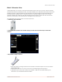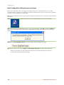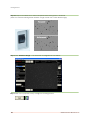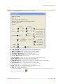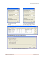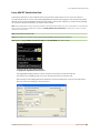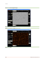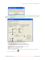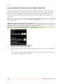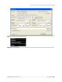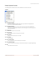
1
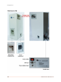
User Manual
© 2009 Nexcelom Bioscience LLC
Technical Support:
Nexcelom Technical Support is available to assist with any technical issues or questions you might have during the
installation or operation of the Cellometer Vision:
Email: [email protected]
Phone: +1-978-327-5340
Fax:
+1-978-327-5341
Technical Support is available: Monday – Friday 8:00 AM to 5:00 PM Eastern US Time.
Warranty Information
Nexcelom warrants that Nexcelom instrumentation products shall, for a period of 12 (twelve) months from the date
of purchase, be free of any defect in material and workmanship. The sole obligation of this warranty shall be to
either repair or replace at our expense the product, at manufacturers option. The original sales receipt must be
supplied for warranty repair. Products, which have been subjected to abuse, misuse, vandalism, accident,
alteration, neglect, unauthorized repair or improper installation, will not be covered by warranty.
Any Product being returned is to be properly disinfected and packaged (in original packing if possible). Damage
sustained in shipping due to improper packing will not be covered by warranty.
A valid Return Material Authorization Number (RMA#) is required for all warranty repairs. For RMA instructions,
please contact our customer service department at 978-327-5340 or email [email protected].
License Agreement
This agreement states the terms and conditions upon which Nexcelom Bioscience LLC (Nexcelom) offers to
license to you the software together with all related documentation. The Software is licensed to you for use only in
conjunction with Nexcelom’s family of products.
Limitation of Liability (Hardware and Software)
Cellometer® branded automatic cell counting instruments, software and consumables are intended for research
use only.
In no event shall Nexcelom be liable for any damages whatsoever (including, without limitation, incidental, direct,
indirect, special or consequential damages, damages for loss of business profits, business interruption, loss of
business information) arising out of the use or inability to use this Software, Consumables or related Hardware.
All rights reserved. No parts of this work may be reproduced in any form or by any means - graphic, electronic, or mechanical,
including photocopying, recording, taping, or information storage and retrieval systems - without the written permission of
Nexcelom Bioscience LLC.
Other products that are referred to in this document may be either trademarks and/or registered trademarks of the respective
owners. Nexcelom makes no claim to these trademarks.
While every precaution has been taken in the preparation of this document, Nexcelom assumes no responsibility for errors or
omissions, or for damages resulting from the use of information contained in this document or from the use of programs and
source code that may accompany it. In no event shall the publisher and the author be liable for any loss of profit or any other
commercial damage caused or alleged to have been caused directly or indirectly by this document.
Table of Contents
Part I Introduction
6
.................................................................................................... 7
What is Cellometer Vision
.................................................................................................... 9
Quick Operation Instructions
Software Overview
.................................................................................................... 11
Terms and Icons Used .................................................................................................... 13
Part II Getting Started
16
....................................................................................................
17
Cellometer Vision System
Components
.................................................................................................... 19
Setting up Cellometer Vision
....................................................................................................
20
Initial Configuration: Setting
Background Image
21
Using Vision for the First....................................................................................................
Time
26
Part III Tutorials
Tutorial Overview
.................................................................................................... 27
....................................................................................................
28
Assay #01 Total Cell Concentration
Measurement
.................................................................................................... 33
Assay #02 Trypan Blue Viability
....................................................................................................
37
Assay #03 GFP Transfection
Rate
....................................................................................................
45
Assay #04 RFP Transfection
Rate
....................................................................................................
52
Assay #05 YFP Transfection
Rate
Assay #06 White Blood Cell Concentration in Whole Blood with
.................................................................................................... 59
Acridine Orange Staining
....................................................................................................
63
Assay #07 PBMC Concentration
Using Acridine Orange Staining
67
Assay #08 Cell Viability....................................................................................................
Using Propidium Iodide Staining
....................................................................................................
72
Assay #09 Live Cell Concentration
using Calcein AM
Assay #10 Sperm Cell Concentration Using Propidium Iodide
.................................................................................................... 76
Staining
....................................................................................................
79
Assay #11 Splenocyte Concentration
and Viability Using AO/PI
....................................................................................................
84
Assay #12 Splenocyte Concentration
and Viability Using AO/EB
.................................................................................................... 90
Modify Default Assay Parameters
Part IV Operation Reference
94
.................................................................................................... 95
Software Operation Overview
.......................................................................................................................................................... 95
File
..........................................................................................................................................................
96
Assay
Type
.......................................................................................................................................................... 102
Options
.......................................................................................................................................................... 104
Help
© 2009 Nexcelom Bioscience LLC
3
Vision Manual
Part V Technical Information
106
Specifications
.................................................................................................... 107
Getting Support
.................................................................................................... 108
Warranty Information .................................................................................................... 109
4
© 2009 Nexcelom Bioscience LLC
Introduction
Introduction
6
© 2009 Nexcelom Bioscience LLC
What is Cellometer Vision
What is Cellometer Vision
Cellometer® Vision is a compact, automated cell analysis system that can count cells, measure cell sizes,
and detect fluorescence properties of cells. The basic principle of the Cellometer automatic cell counter is
imaging cytometry. Cells are loaded into the Disposable Counting Chamber and automatically spread
into a thin layer by capillary action. Cellometer Vision then captures images of cells in the counting
chamber, analyzes the number of cells, sizes and fluorescence intensity of each cell, then converts this
data into concentration, size and fluorescence histograms and scatter plots.
The Cellometer Vision system consists of 3 main components:
1. Cellometer Vision instrument:
2. Cellometer Vision Software and Controller Laptop (Included with instrument and pre-loaded with
software)
3. Disposable Counting Chambers
• Each disposable counting chamber accommodates 2 individual samples and can be loaded
through either port.
• Simply pipette 20µL into one of the ports with any standard single channel pipette.
• Cellometer Vision comes with a starter set of 25 slides. Slides can be ordered directly from
Nexcelom or your authorized Nexcelom dealer.
© 2009 Nexcelom Bioscience LLC
Vision Manual
7
Introduction
Generating Data with Cellometer Vision
Generating cell sample information is quick and easy. Once the instrument is setup for your particular
assay, only 3 basic steps are needed to get results:
1. prepare sample and load
counting chamber
8
2. Insert counting chamber into
instrument
3. Use Software to acquire images,
analyze samples, and view results
© 2009 Nexcelom Bioscience LLC
Quick Operation Instructions
Quick Operation Instructions
Below are the basic steps that are followed to run any assay:
Step
1.
Instructions:
Setup or Select an Assay.
(a) Import or Setup a new assay from the
Assay Type drop down menu, (b) Select an
existing assay from the drop down list or (c)
edit an existing assay.
a. and c.
2.
Input Sample ID and Dilution Factor.
3.
Prepare sample, load disposable counting
chamber and insert into instrument.
4.
Click 'Preview Brightfield Image' and ensure
image is in focus.
5.
Adjust Focus
b.
Slowly turn the black focus wheel until optimal
cell counting focus is achieved. Live cells and
training beads will have a bright center and a
clear defined edge.
6.
Click 'Preview F1 Image' and adjust exposure
time if necessary.
If using Cellometer Vision Trio in dual
fluorescence mode: click 'Preview F2 Image'
and adjust exposure time if necessary
7.
Click 'Count' to begin counting process.
© 2009 Nexcelom Bioscience LLC
Vision Manual
9
Introduction
8.
Review Counting Results and generate
desired reports.
Counting results will automatically display
on-screen. Select desired reports/graphs to
display, export/print data, or click Done to
clear window and review on-screen images.
9.
Navigate and review images on screen:
(a) Select a section of the image to view, (b)
toggle between the brightfield (BR) and
fluorescence (F1 or F2) images, or (c)
manually adjust counted cells
a.
10.
10
If desired, click (a) Re-display Counting
Results, (b) Launch Sample Adjustment
Calculator, or (c) Display Size Distribution
b.
a.
b.
c.
c.
© 2009 Nexcelom Bioscience LLC
Software Overview
Software Overview
Item: Name:
1 Select Assay
2 Modify Assay
3 Cell Type Display
4 Modify Cell Type
5 Imaging Mode Display
6 Sample ID Input
7 Dilution Factor Input
8 Preview Brightfield Image
9 Preview F1 Image
10 F1 Exposure Adjustment
11 Preview F2 Image
12 F2 Exposure Adjustment
13 Count (or Speed Count) Button
14 Recount Button
15 Display Counting Results
16 Sample Adjustment Calculator
17 Display Size Distirbution
18 Live Cell Count Display
19 Trypan Blue Dead Display
20 F1 Counted
© 2009 Nexcelom Bioscience LLC
What it does:
Selects a saved assay from the Assay Library
Modifies parameters of currently selected Assay
Displays the selected cell type
Modifies parameters of currently selected Cell Type
Displays current imaging mode settings
Allows user to input name/ID/# of current sample
Allows user to input dilution factor
Previews brightfield image before counting
Previews the fluorescent image: F1
Adjusts exposure time for F1 image (in milliseconds)
Previews the fluorescent image: F2
Adjusts exposure time for F2 image (in milliseconds)
Initiates counting procedure
Recounts currently loaded image
Opens counting results box
Launches Sample Adjustment Calculator
Opens size distribution histograms
Shows number of live cells in current view
Shows number of Trypan Blue stained (dead) cells in current
view
Shows number of fluorescent positive cells in F1 image
Vision Manual
11
Introduction
21
22
23
24
F2 Counted
Tint F
Captured Image Selection
Captured Image Quadrant Buttons
25 Imaging Mode View Selection
26
27
28
29
30
12
Combine
Counted
Live/Dead Count in View
Manual Adjust
Enter
Shows number of fluorescent positive cells in F2 image
Check to display fluorescent cells in false color
Toggles view between A, B, C, and D captured images
Toggles view between quadrant 1, 2, 3 and 4 of each captured
image
Toggles view between Brightfield (BR), Fluorescence 1(F1) and
Fluorescence 2 (F2)
Displays an overlay of F1 and F2 images
Displays counted images
Displays total number of live or dead counted cells in view
Allows user to manually adjust counting results.
Updates counting results after entering Manual Adjust values
© 2009 Nexcelom Bioscience LLC
Terms and Icons Used
Terms and Icons Used
Assay
A set of configuration parameters that include the instrument settings, i.e. fluorescence
modes, exposure times, counting method and associated cell types.
Cell Type
A set of configuration parameters specific to a cell used in an assay such as cell size,
Parameters fluorescence properties and decluster properties
Decluster A software function used to distinguish and individually count cells from a cluster of cells
Brightfield A standard imaging mode of the instrument using brightfield optics for viewing and
counting total cells, measuring cell sizes and determining viability using trypan blue
Fluorescence The fluorescence imaging capabilities and modes of the instrument. Used to detect
fluorescence properties of cells. Vision Duo has one fluorescence channel, while Vision Trio
has two.
Brightfield Image displayed on screen after it has been acquired from the brightifeld optics.
Image
Fluorescent Image displayed on screen after it has been acquired from the fluorescence optics.
Image
F1, F2
F1 is the first fluorescence image. F2 is the second fluorescence image.
Threshold The limit to include or exclude a cell in a particular category (counted, not counted,
live/dead, fluorescence positive/negative, etc.) based on a particular property of the cell
(i.e. size, fluorescence level, bright center, etc)
Count
The command to initiate an image capture and analysis of a sample
Speed Count The command to initiate an image capture and analysis of a sample in Speed Count mode
Modify Assay or Cell Type parameters: click to quickly access parameters from the main
screen.
Generate Data and Reports: click to view Counting Results box after initial pop-up screen
has been cleared.
Sample Adjustment Calculator: click to display the Sample Adjustment Calculator. Useful
for sample adjustment to get desired concentration or total cell number.
View Size Distribution: click to display size distribution after the initial pop up box has been
cleared.
Recount: click to recount the same acquired image after Assay or Cell parameters have
been modified.
Green Circle: Indicates a counted cell. In brightfield mode, indicates a live cell when
running Trypan Blue assays. In fluorescent mode, indicates a fluorescence positive cell.
Red Circle: In brightfield mode, indicates a dead cell (Trypan Blue Positive) when running
Trypan Blue assays. In fluorescent mode, indicates a fluorescence negative cell.
© 2009 Nexcelom Bioscience LLC
Vision Manual
13
Getting Started
Getting Started
16
© 2009 Nexcelom Bioscience LLC
Cellometer Vision System Components
Cellometer Vision System Components
The Cellometer Vision comes with the following components:
• Cellometer Vision Instrument
• Laptop Controller (and associated accessories and documentation)
• USB 2.0 Cable
• Cellometer Vision Power Supply
• Cellometer Vision Software CD
• User’s Manual
• Consumable Starter Pack (Disposable Counting Chamber Slides and Training Bead Solution)
© 2009 Nexcelom Bioscience LLC
Vision Manual
17
Getting Started
18
© 2009 Nexcelom Bioscience LLC
Setting up Cellometer Vision
Setting up Cellometer Vision
All Nexcelom products undergo a rigorous quality inspection prior to shipment and all reasonable
precautions are taken in preparing them for shipment to assure safe delivery.
The instrument should be unpacked and inspected for mechanical damage upon receipt. Mechanical
inspection involves checking for signs of physical damage such as: broken knobs, scratches, dents, etc.
If damage is apparent, or any components are missing, please immediately contact Nexcelom
(+1-978-327-5340 or [email protected]) or your local dealer.
After unpacking the instrument and laptop, plug the Cellometer Power Cable into the back of the
instrument, and connect the instrument to the laptop using the enclosed USB 2.0 cable. If you use a
computer that is not supplied directly from Nexcelom Bioscience (or Authorized Distributor), the software
must be installed BEFORE the USB 2.0 cable is connected. If you are using a computer supplied directly by
Nexcelom Bioscience (or authorized distributor), connect the instrument to the computer with the enclosed
USB 2.0 cable.
The laptop is pre-configured with Cellometer Vision software and Microsoft Excel (North America only). No
additional setup or configuration is required. If software re-installation is required, please contact
Nexcelom Technical Support or your local dealer.
Connecting Cellometer Vision to Laptop
© 2009 Nexcelom Bioscience LLC
Vision Manual
19
Getting Started
Initial Configuration: Setting Background Image
Before using Cellometer Vision, a background image (image of the system itself without a counting
chamber) must be obtained to normalize the instrument. Unless the instrument is moved, there is generally
no need to take a background image again.
Step 1. Ensure Cellometer Vision is connected to the laptop controller and turn on both the Cellometer and
the Laptop
Step 2. Double Click on the Cellometer Vision icon on the Laptop desktop to launch the software
Step 3. The first time the software launches, you may see this message. Click 'OK' to continue. NOTE: You
will not see this message when using a laptop supplied directly by Nexcelom Bioscience (or Authorized
Distributor).
Step 4. Click 'Preview Brightfield Image' and verify a gray uniform background image.
Step 5. From the Menu bar, select 'Options' > 'Take Background image' to begin image acquisition.
NOTE: This procedure can take several seconds since it automatically adjusts the exposure
to obtain the optimal background image.
20
© 2009 Nexcelom Bioscience LLC
Using Vision for the First Time
Using Vision for the First Time
Before using Cellometer Vision for running samples, use the training bead solution to ensure the instrument
is setup and configured properly.
Step 1.
• Vortex Training Bead Solution at low speed for 10 seconds
• Remove a clean Disposable Counting Chamber and place on a clean Kimwipe
• Pipette all 20µL of solution into one side of the chamber. Capillary force automatically spreads the
sample within the counting chamber.
• Hold the loaded chamber in the white area (taking care to stay away from the clear optical
window area). Insert chamber into slot in the front of the instrument.
Step 2. Select “Training Beads” from the Assay type drop down menu
Step 3. Click 'Preview Brightfield Image'. You should see an image similar to the one below:
© 2009 Nexcelom Bioscience LLC
Vision Manual
21
Getting Started
Step 4. Slowly turn the black focus wheel until optimal cell counting focus is achieved:
(NOTE: Live cells and training beads will have a bright center and a clear defined edge)
Step 5. Click 'Preview F1 Image'. You should see an image like the one below:
Step 6. Click Count (or Speed Count) to begin the counting process.
22
© 2009 Nexcelom Bioscience LLC
Using Vision for the First Time
Step 7. The counting results box will display upon conclusion of the counting process. You should see cell
counts in both the brightfield and fluorescence boxes. The results should be approximately what is
pictured below. If the these figures are grossly out of range, please contact Nexcelom support at
+1-978-327-5340 or [email protected], or your authorized distributor.
Initial setup and configuration are now complete. You are ready to start using Cellometer Vision.
Section III contains tutorials of common applications to help familiarize yourself with the instrument
and its functions.
© 2009 Nexcelom Bioscience LLC
Vision Manual
23
Tutorials
Tutorials
26
© 2009 Nexcelom Bioscience LLC
Tutorial Overview
Tutorial Overview
The following tutorials are intended as a guide to performing various cell-based assays using the Vision.
General sample preparation hints are included for each tutorial as well as instrument and software
operation instructions. Each of the assays can also be performed using the sample images included in the
software as a demonstration of instrument and software operation. Sample images for each assay can be
found at: C:\Program Files\Nexcelom_Vision\Assay_Images
Note: Assay parameters for assays that are included in the software are locked and can not be edited. To
customize any assay to suit your particular application, please see Modify Default Assay Parameters for
instructions on how to modify and save as a new Assay.
© 2009 Nexcelom Bioscience LLC
Vision Manual
27
Tutorials
Assay #01 Total Cell Concentration Measurement
After taking brightfield images of a cell sample, all cells are counted to determine total cell concentration.
Note: Assay parameters for assays that are included in the software are locked and can not be edited. To customize this
assay to suit your particular application, please see Modify Default Assay Parameters for instructions on how to modify
and save as a new assay.
Step 1. Prepare cells suspended in growth media or PBS
Step 2. Load 20µL of cell sample in one side of the cell counting chamber and insert into instrument
Step 3. Select Assay #01_Concentration from Assay SETUP drop-down menu:
Step 4. Click 'Preview Brightfield image':
Step 5. Adjust focus if necessary
Step 6. Click 'Count'
28
© 2009 Nexcelom Bioscience LLC
Assay #01 Total Cell Concentration Measurement
Step 7. Review Counting Results and display data as needed:
a. Count: total number of cells counted
b. Mean Size: mean diameter of the counted cells
c. Concentration: cell concentration (/mL)
d. Show Size Distribution: displays cell size histogram generated using brightfield image
e. Sample Adjustment: launch sample adjustment calculator
f. Save to Data File: record counting results to a data file
g. Export: stores all raw data, assay parameters and graphs in an Excel file
h. Print: send current counting results to printer
i. Done: close counting results window
Note: After clicking 'Done' the counting results box can be redisplayed at any time by clicking on the 'View
Report of Counting Results' button:
© 2009 Nexcelom Bioscience LLC
Vision Manual
29
Tutorials
(d) Show Size Distribution:
Print: print cell size histogram
Save As: save cell diameter values to a data file
Open Diameter File: open an existing cell diameter file
Multiple: check to load and display multiple cell diameter files (up to 5)
Copy to Clipboard: copy diameter data and histogram to Clipboard. This data can be
pasted into a Word, Excel or PowerPoint document
OK
Cancel
30
© 2009 Nexcelom Bioscience LLC
Assay #01 Total Cell Concentration Measurement
(e) Sample Adjustment:
Measured Concentration: cell concentration measured by Cellometer
Original Sample Volume: total volume of cell sample
Total Cell Number in Sample: total number of cells in the original sample
Sample Adjustment: instructions for sample adjustment to obtain desired results
Calculator #1: adjust to obtain target cell
concentration
Target Concentration: desired cell
concentration (/mL)
Apply Change: to calculate adjustment
© 2009 Nexcelom Bioscience LLC
Calculator #2: adjust for target number of
cells
Target Number of Cells: desired number of
cells
Vision Manual
31
Tutorials
Step 8. Review Images on-screen
A: one of the four captured images
1, 2, 3 or 4: one quadrant of a selected image
F1: fluorescence 1 image view
F2: fluorescence 2 image view
Combined: check to display an overlay of F1 and F1 images
Counted: check to see counted cells outlined
When both fluorescence channels are used check the Combined box to display an overlay of F1
and F2 captured images.
A. Cell Image before counting
32
B. Counted cell image. Green outline
indicate counted cells
© 2009 Nexcelom Bioscience LLC
Assay #02 Trypan Blue Viability
Assay #02 Trypan Blue Viability
Trypan blue is routinely used to determine cell viability. Trypan blue penetrates and stains dead cells and
leaves live cells unstained. After taking brightfield images of the stained sample, live and dead cells are
counted to determine total, live and dead cell concentrations as well as compute percent viability.
Note: Assay parameters for assays that are included in the software are locked and can not be edited. To customize this
assay to suit your particular application, please see Modify Default Assay Parameters for instructions on how to modify
and save as a new assay.
Step 1. Mix cell sample with trypan blue and incubate using the same method as when manually counting
Step 2. Load 20µL of cell sample in one side of the cell counting chamber and insert into instrument
Step 3. Select Assay #02_Trypan Blue Viability from Assay SETUP drop-down menu:
Image mode: Brightfield Only
To review Assay Type details: click Edit Assay Button (The yellow pencil next to Assay SETUP)
Check Trypan Blue Viability
© 2009 Nexcelom Bioscience LLC
Vision Manual
33
Tutorials
Step 4. Click 'Preview Brightfield Image':
Step 5. Input Dilution factor (Dilution = 2 if one part sample is added to one part trypan blue.) This will
ensure that counting results reflect cell concentration of original sample.
Step 6. Adjust focus if necessary
Step 7. Click 'Count'
34
© 2009 Nexcelom Bioscience LLC
Assay #02 Trypan Blue Viability
Step 8. Review Counting Results and display data as needed:
a. Count: total number of cells counted
b. Trypan Blue Dead Count: number of trypan blue positive (dead) cells
c. Mean Size: mean diameter of the live cells
d. Viability by Trypan Blue: percentage of live cells out of total number of cells measured using trypan blue
method
e. Concentration: live cell concentration (/mL)
f. Show Size Distribution: display cell size histogram
g. Sample Adjustment: launch sample adjustment calculator
h. Save to Data File: record counting results in a table
i. Export: stores all raw data, assay parameters and graphs in an Excel file
j. Print: send the current counting results to a printer
k. Done: closes counting results window
Note: After clicking 'Done' the counting results box can be redisplayed at any time by clicking on the 'View
Report of Counting Results' button:
© 2009 Nexcelom Bioscience LLC
Vision Manual
35
Tutorials
Step 9. Review Images on-screen
A: one of the four captured images
1, 2, 3 or 4: one quadrant of a selected image
F1: fluorescence 1 image view
F2: fluorescence 2 image view
Combined: check to display an overlay of F1 and F1 images
Counted: check to see counted cells outlined
When both fluorescence channels are used check the Combined box to display an overlay of F1
and F2 captured images.
A. Cell image before counting
36
B. Cell image after counting. Green outline
indicates live cells and red outline indicates
trypan blue positive dead cells.
© 2009 Nexcelom Bioscience LLC
Assay #03 GFP Transfection Rate
Assay #03 GFP Transfection Rate
Transfection efficiency is often determined by using a GFP marker (either on the vector of interest or
co-transfected with the vector). After taking brightfield and fluorescent images of the transfected sample,
all cells are counted in brightfield and fluorescent images. Transfection efficiency is computed by dividing
the number of fluorescent cells by the total number of cells.
Note: Assay parameters for assays that are included in the software are locked and can not be edited. To customize this
assay to suit your particular application, please see Modify Default Assay Parameters for instructions on how to modify
and save as a new assay.
Step 1. Trypsinize attached cells
Step 2. Load 20µL in one side of the cell counting chamber and insert into instrument
Step 3. Select Assay #03_GFP_Transfection Rate from Assay SETUP drop-down menu:
Cell Type: HCT is displayed.
Imaging Mode: Brightfield and Fluorescence
The brightfield imaging mode is used to measure total number of cells and cell size.
The fluorescence imaging mode is used to measure fluorescence positive cells.
Both Cell Type and Imaging Mode are defined in the Assay parameters, and can be edited from
the main screen by clicking on the pencil icon.
© 2009 Nexcelom Bioscience LLC
Vision Manual
37
Tutorials
Step 4. Click 'Preview brightield Image'
Step 5. Adjust Focus if necessary
Step 6. Click 'Preview F1 Image' (Fluorescence)
Step 7. Click 'Count'
38
© 2009 Nexcelom Bioscience LLC
Assay #03 GFP Transfection Rate
Step 8. Review Counting Results and display data as needed:
a.
b.
c.
d.
e.
f.
g.
Count / brightfield: total number of cells counted in the brightfield image
Count / Fluorescence: number of fluorescence positive cells counted
Mean Size / brightfield: mean diameter of cells measured in brightfield
Mean Size / Fluorence: mean diameter of fluorescence positive cells
Concentration / Bright Field: total cell concentration (/mL)
Concentration / Fluorescence: fluorescence cell concentration (/mL)
F1 Count / BR Total Count: transfection rate
h. Show Size Distribution: displays cell size histogram generated using brightfield image
i. Intensity Distribution: displays fluorescence cell intensity histogram
j. Size vs Intensity: displays fluorescence intensity vs. cell size scatterplot
k. Sample Adjustment: calculates adjustment for target concentration or target number of cells
l. Set Data File: creates a data file to store cell counting table
m. Save to Data File: records counting results in the cell counting table
n. View Data File: displays currently selected cell counting table
o. Export: stores all raw data, assay parameters and graphs in an Excel file
p. Print: sends the current counting results to a printer
q. Done: closes counting results window
Note: After clicking 'Done' the Counting Results box can be redisplayed at any time by clicking on the 'View
Report of Counting Results' button:
© 2009 Nexcelom Bioscience LLC
Vision Manual
39
Tutorials
(h) cell size distribution for brightfield image:
NOTE: this can be instantly displayed at any time by clicking on the
icon.
(i) Fluorescence intensity versus number of cells:
(j) Fluorescence intensity versus cell size:
40
© 2009 Nexcelom Bioscience LLC
Assay #03 GFP Transfection Rate
(k) Sample Adjustment Calculator:
Calculator #1: input target cell
concentration and calculate
adjustment
Calculator #2: input target number of
needed. Amount of sample to add and
the number of aliquots will be calculated
(n) View Data table: Cell Counting Table list saves counting results from multiple samples:
(o) Export all raw data, assay type, cell type, etc into an excel file:
NOTE: User can select which items get exported to Excel.
© 2009 Nexcelom Bioscience LLC
Vision Manual
41
Tutorials
Step 9. Review Images on-screen
A: one of the four captured images
1, 2, 3 or 4: one quadrant of a selected image
F1: fluorescence 1 image view
F2: fluorescence 2 image view
Combined: check to display an overlay of F1 and F1 images
Counted: check to see counted cells outlined
When both fluorescence channels are used check the Combined box to display an overlay of F1
and F2 captured images.
A. Brightfield cell image
42
B. Counted cells indicated
by the green outline
© 2009 Nexcelom Bioscience LLC
Assay #03 GFP Transfection Rate
C. Fluorescence cell image D. Counted fluorescence
positive cells indicated by
the green outline. The red
outline indicated cells that
are fluorescence negative.
© 2009 Nexcelom Bioscience LLC
Vision Manual
43
Tutorials
Step 10. To adjust fluorescence threshold (to determine which cells are counted as fluorescent positive or
negative) adjust Cell Type Parameters by clicking on the pencil icon next to Cell Type.
Fluorescence Threshold is user defined to identify the brightness at which a cell is defined as positive:
GFP fluorescence image
44
Threshold = 3%
F1 positive rate = 58.2%
Threshold = 20%
F1 positive rate = 28.9%
Increase threshold value counted
only high intensity fluorescence
as positive.
© 2009 Nexcelom Bioscience LLC
Assay #04 RFP Transfection Rate
Assay #04 RFP Transfection Rate
Transfection efficiency is often determined by using an RFP marker (either on the vector of interest or
co-transfected with the vector). After taking brightfield and fluorescent images of the transfected sample,
all cells are counted in brightfield and fluorescent images. Transfection efficiency is computed by dividing
the number of fluorescent cells by the total number of cells.
Note: Assay parameters for assays that are included in the software are locked and can not be edited. To customize this
assay to suit your particular application, please see Modify Default Assay Parameters for instructions on how to modify
and save as a new assay.
Step 1. Trypsinize attached cells
Step 2. Load 20µL in one side of the cell counting chamber and insert into instrument
Step 3. Select Assay #04 RFP Transfection Rate from Assay SETUP drop-down menu:
Cell Type:Cell Line_Assay #04 is displayed.
Imaging Mode: Brightfield and Fluorescence
The brightfield imaging mode is used to measure total number of cells and cell size.
The fluorescence imaging mode is used to measure fluorescence positive cells.
Both Cell Type and Imaging Mode are defined in the Assay parameters, and can be edited from
the main screen by clicking on the pencil icon.
© 2009 Nexcelom Bioscience LLC
Vision Manual
45
Tutorials
Step 4. Click 'Preview brightield Image'
Step 5. Adjust Focus if necessary
Step 6. Click 'Preview F1 Image' (Fluorescence)
Step 7. Click 'Count'
46
© 2009 Nexcelom Bioscience LLC
Assay #04 RFP Transfection Rate
Step 8. Review Counting Results and display data as needed:
a.
b.
c.
d.
e.
f.
g.
Count / brightfield: total number of cells counted in the brightfield image
Count / Fluorescence: number of fluorescence positive cells counted
Mean Size / brightfield: mean diameter of cells measured in brightfield
Mean Size / Fluorence: mean diameter of fluorescence positive cells
Concentration / Bright Field: total cell concentration (/mL)
Concentration / Fluorescence: fluorescence cell concentration (/mL)
F1 Count / BR Total Count: transfection rate
h. Show Size Distribution: displays cell size histogram generated using brightfield image
i. Intensity Distribution: displays fluorescence cell intensity histogram
j. Size vs Intensity: displays fluorescence intensity vs. cell size scatterplot
k. Sample Adjustment: calculates adjustment for target concentration or target number of cells
l. Set Data File: creates a data file to store cell counting table
m. Save to Data File: records counting results in the cell counting table
n. View Data File: displays currently selected cell counting table
o. Export: stores all raw data, assay parameters and graphs in an Excel file
p. Print: sends the current counting results to a printer
q. Done: closes counting results window
Note: After clicking 'Done' the Counting Results box can be redisplayed at any time by clicking on the 'View
Report of Counting Results' button:
© 2009 Nexcelom Bioscience LLC
Vision Manual
47
Tutorials
(h) cell size distribution for brightfield image:
NOTE: this can be instantly displayed at any time by clicking on the
icon.
(i) Fluorescence intensity versus number of cells:
(j) Fluorescence intensity versus cell size:
48
© 2009 Nexcelom Bioscience LLC
Assay #04 RFP Transfection Rate
(k) Sample Adjustment Calculator:
Calculator #1: input target cell
concentration and calculate
adjustment
© 2009 Nexcelom Bioscience LLC
Calculator #2: input target number of
needed. Amount of sample to add and
the number of aliquots will be calculated
Vision Manual
49
Tutorials
Step 9. Review Images on-screen
A: one of the four captured images
1, 2, 3 or 4: one quadrant of a selected image
F1: fluorescence 1 image view
F2: fluorescence 2 image view
Combined: check to display an overlay of F1 and F1 images
Counted: check to see counted cells outlined
When both fluorescence channels are used check the Combined box to display an overlay of F1
and F2 captured images.
A. Brightfield cell image
50
B. Counted cells
© 2009 Nexcelom Bioscience LLC
Assay #04 RFP Transfection Rate
C. RFP positive cell image
© 2009 Nexcelom Bioscience LLC
D. Green outline indicates counted
RFP positive cells
Vision Manual
51
Tutorials
Assay #05 YFP Transfection Rate
Transfection efficiency is often determined by using a YFP marker (either on the vector of interest or
co-transfected with the vector). After taking brightfield and fluorescent images of the transfected sample,
all cells are counted in brightfield and fluorescent images. Transfection efficiency is computed by dividing
the number of fluorescent cells by the total number of cells.
Note: Assay parameters for assays that are included in the software are locked and can not be edited. To customize this
assay to suit your particular application, please see Modify Default Assay Parameters for instructions on how to modify
and save as a new assay.
Step 1. Trypsinize attached cells
Step 2. Load 20µL in one side of the cell counting chamber and insert into instrument
Step 3. Select Assay #05 YFP Transfection Rate from Assay SETUP drop-down menu:
Cell Type: Cell Line_No decluster_Assay #05 is displayed.
Imaging Mode: Brightfield and Fluorescence
The brightfield imaging mode is used to measure total number of cells and cell size.
The fluorescence imaging mode is used to measure fluorescence positive cells.
Both Cell Type and Imaging Mode are defined in the Assay parameters, and can be edited from
the main screen by clicking on the pencil icon.
52
© 2009 Nexcelom Bioscience LLC
Assay #05 YFP Transfection Rate
Step 4. Click 'Preview brightield Image'
Step 5. Adjust Focus if necessary
Step 6. Click 'Preview F1 Image' (Fluorescence)
Step 7. Click 'Count'
© 2009 Nexcelom Bioscience LLC
Vision Manual
53
Tutorials
Step 8. Review Counting Results and display data as needed:
a.
b.
c.
d.
e.
f.
g.
Count / brightfield: total number of cells counted in the brightfield image
Count / Fluorescence: number of fluorescence positive cells counted
Mean Size / brightfield: mean diameter of cells measured in brightfield
Mean Size / Fluorence: mean diameter of fluorescence positive cells
Concentration / Bright Field: total cell concentration (/mL)
Concentration / Fluorescence: fluorescence cell concentration (/mL)
F1 Count / BR Total Count: transfection rate
h. Show Size Distribution: displays cell size histogram generated using brightfield image
i. Intensity Distribution: displays fluorescence cell intensity histogram
j. Size vs Intensity: displays fluorescence intensity vs. cell size scatterplot
k. Sample Adjustment: calculates adjustment for target concentration or target number of cells
l. Set Data File: creates a data file to store cell counting table
m. Save to Data File: records counting results in the cell counting table
n. View Data File: displays currently selected cell counting table
o. Export: stores all raw data, assay parameters and graphs in an Excel file
p. Print: sends the current counting results to a printer
q. Done: closes counting results window
Note: After clicking 'Done' the Counting Results box can be redisplayed at any time by clicking on the 'View
Report of Counting Results' button:
54
© 2009 Nexcelom Bioscience LLC
Assay #05 YFP Transfection Rate
(h) cell size distribution for brightfield image:
NOTE: this can be instantly displayed at any time by clicking on the
icon.
(i) Fluorescence intensity versus number of cells:
(j) Fluorescence intensity versus cell size:
© 2009 Nexcelom Bioscience LLC
Vision Manual
55
Tutorials
(k) Sample Adjustment Calculator:
Calculator #1: input target cell
concentration and calculate
adjustment
56
Calculator #2: input target number of
needed. Amount of sample to add and
the number of aliquots will be calculated
© 2009 Nexcelom Bioscience LLC
Assay #05 YFP Transfection Rate
Step 9. Review Images on-screen
A: one of the four captured images
1, 2, 3 or 4: one quadrant of a selected image
F1: fluorescence 1 image view
F2: fluorescence 2 image view
Combined: check to display an overlay of F1 and F1 images
Counted: check to see counted cells outlined
When both fluorescence channels are used check the Combined box to display an overlay of F1
and F2 captured images.
A. Brightfield cell image
© 2009 Nexcelom Bioscience LLC
B. Counted cells
Vision Manual
57
Tutorials
C. YFP positive cell image
58
D. Green outline indicates counted
YFP positive cells
© 2009 Nexcelom Bioscience LLC
Assay #06 White Blood Cell Concentration in Whole Blood with Acridine Orange Staining
Assay #06 White Blood Cell Concentration in Whole Blood with Acridine
Orange Staining
Determining white blood cell counts in whole blood normally involves a lysis procedure to eliminate red
blood cells. However, WBCs can be counted in whole blood without lysis of RBCs by staining the blood
sample with Acridine orange, a nuclear stain that emits in the ‘green’ range. After taking ‘green’
fluorescent images of AO stained whole blood, all fluorescent cells are counted and their concentration in
whole blood is determined. Brightfield images of the sample can be taken but are not used for WBC
counting. (If RBC counting results are desired, the original blood sample can be diluted approximately
1:1000 and counted using only brightfield images, as in Assay #01)
Note: Assay parameters for assays that are included in the software are locked and can not be edited. To customize this
assay to suit your particular application, please see Modify Default Assay Parameters for instructions on how to modify
and save as a new assay.
Step 1. Dilute blood in PBS 1:10
Step 2. Mix cell samples with AO and incubate using the same method as when manually counting (blood
concentration 1:20, AO concentration 2-10 mg/mL)
Step 3. Load 20µL AO stained cell sample in one side of the cell counting chamber and insert into
instrument
Step 4. Select Assay #06_WBC in Whole Blood from the Assay SETUP drop-down menu:
Imaging mode: Fluorescence Only
Click on the yellow pencil on the right side of Assay selection to view Assay Type
Take BR with FL Image: check to take brightfield image of the same cell sample
© 2009 Nexcelom Bioscience LLC
Vision Manual
59
Tutorials
Use BR cell for F1 Count: uncheck to NOT use brightfield counting method
Step 5. Click 'Preview Brightfield Image'
Step 6. Adjust focus if necessary
Step 7. Click 'Preview F1 Image'
Step 8. Click 'Count'
Step 9. Review Counting Results and display data as needed:
a. Count: total number of white blood cells
b. Concentration: concentration of white blood cells
c. Sample Adjustment: calculates adjustment for target concentration or target number of cells
d. Save to Data File: record counting results in a table
e. Export: stores all raw data, assay parameters and graphs in an Excel file
f. Print: send current counting results to printer
g. Done: closes counting results window
Note: After clicking 'Done' the counting results box can be redisplayed at any time by clicking on the 'View
Report of Counting Results' button:
60
© 2009 Nexcelom Bioscience LLC
Assay #06 White Blood Cell Concentration in Whole Blood with Acridine Orange Staining
Step 10. Review Images on-screen
A: one of the four captured images
1, 2, 3 or 4: one quadrant of a selected image
F1: fluorescence 1 image view
F2: fluorescence 2 image view
Combined: check to display an overlay of F1 and F1 images
Counted: check to see counted cells outlined
When both fluorescence channels are used check the Combined box to display an overlay of F1
and F2 captured images.
A. Brightfield image shows sample with
crowded red blood cells.
© 2009 Nexcelom Bioscience LLC
Vision Manual
61
Tutorials
B. Fluorescent cell image before counting
outline
62
C. Fluorescent cell image after counting.
Green indicates counted white blood cells
© 2009 Nexcelom Bioscience LLC
Assay #07 PBMC Concentration Using Acridine Orange Staining
Assay #07 PBMC Concentration Using Acridine Orange Staining
PBMC preparations generally contain some RBCs making it difficult to accurately count only the PBMCs.
RBCs can be eliminated to improve counting by using a lysis procedure. However, PBMCs can be
selectively counted without lysis of RBCs by staining the PBMC preparation with Acridine orange, a nuclear
stain that emits in the ‘green’ range. After taking ‘green’ fluorescent images, all fluorescent cells are
counted and their concentration in the PBMC preparation is determined. Brightfield images of the sample
can be taken but are not used for PBMC counting.
Note: Assay parameters for assays that are included in the software are locked and can not be edited. To customize this
assay to suit your particular application, please see Modify Default Assay Parameters for instructions on how to modify
and save as a new assay.
Step 1. Mix cell sample with AO and incubate using the same method as when manually counting (AO
concentration 2-10 mg/mL)
Step 2. Load 20µL in one side of the cell counting chamber and insert into instrument
Step 3. Select Assay #07_PBMC with AO from the Assay SETUP drop-down menu:
Image mode: Fluorescence Only
Click on the yellow pencil on the right side of Assay selection to view Assay Type
Take BR with FL Image: check to take brightfield image of the same cell sample
Use BR cell for F1 Count: uncheck to NOT use brightfield counting method
© 2009 Nexcelom Bioscience LLC
Vision Manual
63
Tutorials
Step 4. Click 'Preview Brightfield Image'
Step 5. Adjust focus if necessary
Step 6. Click 'Preview F1 Image'
Step 7. Click 'Count'
Step 8. Review Counting Results and display data as needed:
a. Count: number PBMC counted
b. Concentration: PBMC concentration /mL
c. Sample Adjustment: calculates adjustment for target concentration or target number of cells
d. Save to Data File: record counting results in a table
e. Export: stores all raw data, assay parameters and graphs in an Excel file
f. Print: send current counting results to printer
g. Done: closes counting results window
Note: After clicking 'Done' the counting results box can be redisplayed at any time by clicking on the 'View
Report of Counting Results' button:
64
© 2009 Nexcelom Bioscience LLC
Assay #07 PBMC Concentration Using Acridine Orange Staining
Step 9. Review Images on-screen
A: one of the four captured images
1, 2, 3 or 4: one quadrant of a selected image
F1: fluorescence 1 image view
F2: fluorescence 2 image view
Combined: check to display an overlay of F1 and F1 images
Counted: check to see counted cells outlined
When both fluorescence channels are used check the Combined box to display an overlay of F1
and F2 captured images.
A. Brightfield image of PBMCs with
contaminating red blood cells
© 2009 Nexcelom Bioscience LLC
Vision Manual
65
Tutorials
B. Fluorescence image of AO stained
PBMCs
66
C. PBMCs after counting. Green
outline indicates counted cells
© 2009 Nexcelom Bioscience LLC
Assay #08 Cell Viability Using Propidium Iodide Staining
Assay #08 Cell Viability Using Propidium Iodide Staining
Propidium iodide is routinely used to determine cell viability. PI is a fluorescent stain that only penetrates
dead cells and emits in the ‘red’ range (live cells are unaffected by PI). After taking both brightfield and ‘
red’ fluorescent images of a PI stained sample, all cells (from brightfield channel) and dead cells (from ‘red
’ fluorescent channel) are counted to determine total and dead cell concentrations and compute the
percent viability.
Note: Assay parameters for assays that are included in the software are locked and can not be edited. To customize this
assay to suit your particular application, please see Modify Default Assay Parameters for instructions on how to modify
and save as a new assay.
Step 1. Mix cell samples with PI and incubate using the same method as when manually counting.
Step 2. Load 20µL stained cell sample in one side of the cell counting chamber and insert into instrument
Step 3. Select Assay #08_PI Viability Jurkat from the Assay SETUP drop-down menu:
Imaging mode: Brightfield and Fluorescence
Click on the yellow pencil on the right side of Assay selection to view Assay Type
Click “Show Report Format” to display all available data display options
© 2009 Nexcelom Bioscience LLC
Vision Manual
67
Tutorials
Step 4. Click 'Preview Brightfield Image'
Step 5. Adjust focus if necessary
Step 6. Click 'Count'
68
© 2009 Nexcelom Bioscience LLC
Assay #08 Cell Viability Using Propidium Iodide Staining
Step 7. Review Counting Results and display data as needed:
a. Count / Bright Field: total number of cells counted in the brightfield image
b. Count / Fluorescence: number of fluorescence positive cells counted
c. Mean Size / Bright Field: mean diameter of cells measured in brightfield
d. Mean Size / Fluorescence: mean diameter of fluorescence positive cells
e. Concentration / Bright Field: total cell concentration (/mL) of original sample
f. Concentration / Fluorescence: fluorescence cell concentration (/mL)
g. (BR-F1 Count) / BR Total Count: % viability of cell sample
h. Export: stores all raw data, assay parameters and graphs in an Excel file
i. Print: send current counting results to printer
j. Done: closes counting results window
Note: After clicking 'Done' the counting results box can be redisplayed at any time by clicking on the 'View
Report of Counting Results' button:
© 2009 Nexcelom Bioscience LLC
Vision Manual
69
Tutorials
Step 8. Review Images on-screen
A: one of the four captured images
1, 2, 3 or 4: one quadrant of a selected image
F1: fluorescence 1 image view
F2: fluorescence 2 image view
Combined: check to display an overlay of F1 and F1 images
Counted: check to see counted cells outlined
When both fluorescence channels are used check the Combined box to display an overlay of F1
and F2 captured images.
A. Brightfield cell image
70
B. Counted cell image. Green outline
indicates counted cells
© 2009 Nexcelom Bioscience LLC
Assay #08 Cell Viability Using Propidium Iodide Staining
C. PI positive fluorescence cell image
© 2009 Nexcelom Bioscience LLC
D. Counted fluorescence cell image.
Green outline indicates PI positive cells.
Vision Manual
71
Tutorials
Assay #09 Live Cell Concentration using Calcein AM
Calcein AM is used to determine cell viability and other key functional activities of cells. Calcein AM is
non-fluorescent but when taken up by live cells, it is converted to calcein, a compound that emits in the ‘
green’ fluorescent range. After taking ‘green’ fluorescent images, all fluorescent cells are counted and
their concentration in the sample is determined. Brightfield images can also be taken and counted.
However, in the sample images for this assay, brightfield counting picked up debris that was eliminated by
imaging in the fluorescent channel.
Note: Assay parameters for assays that are included in the software are locked and can not be edited. To customize this
assay to suit your particular application, please see Modify Default Assay Parameters for instructions on how to modify
and save as a new assay.
Step 1. Mix cell samples with Caiceim AM and incubate according to manufacturer’s instructions.
Step 2. Load 20µL cell sample in one side of the cell counting chamber and insert into instrument.
Step 3. Select Assay #09_Calcein AM_Macrophage from the Assay SETUP drop-down menu:
Image mode: Brightfield and Fluorescence
Click on the yellow pencil on the right side of Assay selection to view Assay Type
Step 4. Click 'Preview Brightfield Image'
Step 5. Adjust focus if necessary
Step 6. Click 'Preview F1 Image'
72
© 2009 Nexcelom Bioscience LLC
Assay #09 Live Cell Concentration using Calcein AM
Step 7. Click 'Count'
Step 8. Review Counting Results and display data as needed:
a. Count / Bright Field: total number of cells counted in the brightfield image
b. Count / Fluorescence: number of fluorescence positive cells counted
c. Mean Size / Bright Field: mean diameter of cells measured in brightfield
d. Concentration / Bright Field: total cell concentration (/mL)
e. Concentration / Fluorescence: fluorescence cell concentration (/mL)
f. Export: stores all raw data, assay parameters and graphs in an Excel file
g. Print: send current counting results to printer
h. Done: closes counting results window
Note: After clicking 'Done' the counting results box can be redisplayed at any time by clicking on the 'View
Report of Counting Results' button:
© 2009 Nexcelom Bioscience LLC
Vision Manual
73
Tutorials
Step 9. Review Images on-screen
A: one of the four captured images
1, 2, 3 or 4: one quadrant of a selected image
F1: fluorescence 1 image view
F2: fluorescence 2 image view
Combined: check to display an overlay of F1 and F1 images
Counted: check to see counted cells outlined
When both fluorescence channels are used check the Combined box to display an overlay of F1
and F2 captured images.
A. Brightfield image of cells.
74
B. Brightfield after counting. This cell sample
contains a large amount of debris which
makes the brightfield counting method less
accurate.
© 2009 Nexcelom Bioscience LLC
Assay #09 Live Cell Concentration using Calcein AM
C. Fluorescence image of Calcein positive
cells
.
© 2009 Nexcelom Bioscience LLC
D. Fluorescence positive cells after counting
Vision Manual
75
Tutorials
Assay #10 Sperm Cell Concentration Using Propidium Iodide Staining
In this assay, propidium iodide staining is used to count all cells in a sperm sample. PI is a fluorescent stain
that emits in the ‘red’ range and is used to mark all sperm after permeabilization. After taking ‘red’
fluorescent images, all fluorescent cells are counted and their concentration in the sample is determined.
This assay demonstrates that the Cellometer software can be used to count non-circular objects such as
sperm.
Note: Assay parameters for assays that are included in the software are locked and can not be edited. To customize this
assay to suit your particular application, please see Modify Default Assay Parameters for instructions on how to modify
and save as a new assay.
Step 1. Stain sperm cells with propidium iodide following manufacturer’s instructions
Step 2. Select Assay #10_PI_Sperm from the Assay SETUP drop-down menu:
Imaging mode: Fluorescence Only
Click on the yellow pencil on the right side of Assay selection to view Assay Type
The Fluorescent Exposure time can be adjusted to obtain adequate signal within a range of PI
concentrations since the signal strength is cell-dependent.
Step 4. Click 'Preview Brightfield Image':
Step 5. Adjust focus if necessary
Step 6. Click 'Count'
76
© 2009 Nexcelom Bioscience LLC
Assay #10 Sperm Cell Concentration Using Propidium Iodide Staining
Step 7. Review Counting Results and display data as needed:
a. Count / Fluorescence: number of fluorescence positive cells counted
b. Concentration / Fluorescence: fluorescence cell concentration (/mL)
c. Export: stores all raw data, assay parameters and graphs in an Excel file
d. Print: send current counting results to printer
e. Done: closes counting results window
Note: After clicking 'Done' the counting results box can be redisplayed at any time by clicking on the 'View
Report of Counting Results' button:
© 2009 Nexcelom Bioscience LLC
Vision Manual
77
Tutorials
Step 8. Review Images on-screen
A: one of the four captured images
1, 2, 3 or 4: one quadrant of a selected image
F1: fluorescence 1 image view
F2: fluorescence 2 image view
Combined: check to display an overlay of F1 and F1 images
Counted: check to see counted cells outlined
When both fluorescence channels are used check the Combined box to display an overlay of F1
and F2 captured images.
A. Cell image before counting
78
B. Cell image after counting. Green outline
indicates sperm cells counted
© 2009 Nexcelom Bioscience LLC
Assay #11 Splenocyte Concentration and Viability Using AO/PI
Assay #11 Splenocyte Concentration and Viability Using AO/PI
Acridine orange is a nuclear stain that emits in the ‘green’ range and is used to stain live cells. Propidium
iodide is a fluorescent stain that only penetrates dead cells and emits in the ‘red’ range. After taking both ‘
green’ and ‘red’ fluorescent images, all fluorescent cells in each channel are counted and the
concentration of live (‘green’ fluorescent) and dead (‘red’ fluorescent) cells as well as viability are
determined.
Note: Assay parameters for assays that are included in the software are locked and can not be edited. To customize this
assay to suit your particular application, please see Modify Default Assay Parameters for instructions on how to modify
and save as a new assay.
Step 1. Mix 10 µl splenocyte sample with 10 µl AOPI mixture
Step 2. Load 20 µl in one cell counting chamber and insert into instrument
Step 3. Select Assay #11_AOPI_Splenocyte from the Assay SETUP drop-down menu:
Cell Type: Splenocyte_Assay #11 is displayed
Imaging Mode: Fluorescent 1, Fluorescent 2
The fluorescent 1 is used to measure live cells, while the fluorescence 2 is used to measure
dead cells.
Both Cell Type and Imaging Mode are defined in the Assay parameters, and can be shown
from the main screen by clicking on the pencil icon.
© 2009 Nexcelom Bioscience LLC
Vision Manual
79
Tutorials
Step 4. Input Sample ID and dilution factor
Step 5. Input “2” for Dilution
Step 6. Review cell images
a. Click 'B1'
b. 'Preview B1' will display brightfield image of F1 channel
c. Adjust Focus if necessary
d. Stop Review
e. Click 'Preview F1' (Fluorescence)
f. 100% of Range indicates adequate exposure time for F1 channel
g. Click ‘Preview F2' (Fluorescence)
80
© 2009 Nexcelom Bioscience LLC
Assay #11 Splenocyte Concentration and Viability Using AO/PI
h. If exposure time is inadequate, increase exposure time by using the pencil tool next to the Assay
Set up drop down menu
Step 7. Review Counting Results and display data as needed:
a. Count / Fluorescent 1: indicates total number of live cells
b. Count / Fluorescent 2: indicates total number of dead cells
c. Concentration/ Fluorescent 1: indicates live cell concentration /(mL)
d. Concentration/ Fluorescent 2: indicates dead cell concentration /(mL)
e. F1 Count /(F1 +F2Count): indicates percentage of live cells to total cells
f. Save to Data File: record counting results in a table
g. Export stores all raw data, assay parameters and graphs in an Excel file
h. Print: send the current Counting Results to a printer
i. Done: closes counting results window
Note: After clicking 'Done' the counting results box can be redisplayed at any time by clicking on the 'View
Report of Counting Results' button:
© 2009 Nexcelom Bioscience LLC
Vision Manual
81
Tutorials
Step 8. Review Images on-screen
A: one of the four captured images
1, 2, 3 or 4: one quadrant of a selected image
F1: fluorescence 1 image view
F2: fluorescence 2 image view
Combined: check to display an overlay of F1 and F1 images
Counted: check to see counted cells outlined
When both fluorescence channels are used check the Combined box to display an overlay of F1
and F2 captured images.
82
© 2009 Nexcelom Bioscience LLC
Assay #11 Splenocyte Concentration and Viability Using AO/PI
A. F1
B. F2
C. Combined
D. Combined and Counted
© 2009 Nexcelom Bioscience LLC
Vision Manual
83
Tutorials
Assay #12 Splenocyte Concentration and Viability Using AO/EB
Acridine orange is a nuclear stain that emits in the ‘green’ range and is used to stain live cells. Ethidium
bromide is a fluorescent stain that only penetrates dead cells and emits in the ‘red’ range. After taking
both ‘green’ and ‘red’ fluorescent images, all fluorescent cells in each channel are counted and the
concentration of live (‘green’ fluorescent) and dead (‘red’ fluorescent) cells as well as viability are
determined.
Note: Assay parameters for assays that are included in the software are locked and can not be edited. To customize this
assay to suit your particular application, please see Modify Default Assay Parameters for instructions on how to modify
and save as a new assay.
Step 1. Mix 10 µl splenocyte sample with 10 µl AOEB mixture
Step 2. Load 20 µl in one cell counting chamber and insert into instrument
Step 3. Select Assay #12_AOEB_Splenocyte from the Assay SETUP drop-down menu:
Cell Type: Splenocyte_Assay #12 is displayed
Imaging Mode: Fluorescent 1, Fluorescent 2
The fluorescent 1 is used to measure live cells, while the fluorescence 2 is used to measure dead
cells.
Both Cell Type and Imaging Mode are defined in the Assay parameters, and can be shown from
the main screen by clicking on the pencil icon.
84
© 2009 Nexcelom Bioscience LLC
Assay #12 Splenocyte Concentration and Viability Using AO/EB
Step 4. Input Sample ID and dilution factor
Step 5. Input “2” for Dilution
© 2009 Nexcelom Bioscience LLC
Vision Manual
85
Tutorials
Step 6. Review cell images
a. Click 'B1'
b. 'Preview B1' will display brightfield image of F1 channel
c. Adjust Focus if necessary
d. Stop Review
e. Click 'Preview F1' (Fluorescence)
f. 100% of Range indicates adequate exposure time for F1 channel
g. Click ‘Preview F2' (Fluorescence)
h. If exposure time is inadequate, increase exposure time by using the pencil tool next to the Assay
Set up drop down menu
86
© 2009 Nexcelom Bioscience LLC
Assay #12 Splenocyte Concentration and Viability Using AO/EB
Step 7. Review Counting Results and display data as needed:
a. Count / Fluorescent 1: indicates total number of live cells
b. Count / Fluorescent 2: indicates total number of dead cells
c. Concentration/ Fluorescent 1: indicates live cell concentration /(mL)
d. Concentration/ Fluorescent 2: indicates dead cell concentration /(mL)
e. F1 Count /(F1 +F2Count): indicates percentage of live cells to total cells
f. Save to Data File: record counting results in a table
g. Export: stores all raw data, assay parameters and graphs in an Excel file
h. Print: send the current Counting Results to a printer
i. Done: closes counting results window
Note: After clicking 'Done' the counting results box can be redisplayed at any time by clicking on the 'View
Report of Counting Results' button:
© 2009 Nexcelom Bioscience LLC
Vision Manual
87
Tutorials
Step 8. Review Images on-screen
A: one of the four captured images
1, 2, 3 or 4: one quadrant of a selected image
F1: fluorescence 1 image view
F2: fluorescence 2 image view
Combined: check to display an overlay of F1 and F1 images
Counted: check to see counted cells outlined
When both fluorescence channels are used check the Combined box to display an overlay of F1
and F2 captured images.
A. FI
88
B. F2
© 2009 Nexcelom Bioscience LLC
Assay #12 Splenocyte Concentration and Viability Using AO/EB
C. Combined
© 2009 Nexcelom Bioscience LLC
D. Combined and Counted
Vision Manual
89
Tutorials
Modify Default Assay Parameters
Vision default assay types are intended as guidelines for setting up new assays. The following is a procedure
to modify an existing assay type to suit specific experiments.
Step 1. Select Assay #03_GFP_Transfection Rate from Assay SETUP drop-down menu:
Step 2. Edit Assay Type by click on the yellow pencil tool
a. Check Save as New Assay Type
b. Input new or modified name in Assay Name (Save will turn on after the assay name is
changed.)
c. Modify cell type if necessary
Method 1: drop-down from F1 Image Cell Type to find another cell type
Method 2. Edit to change current cell type parameters
90
© 2009 Nexcelom Bioscience LLC
Modify Default Assay Parameters
Check Save as New Cell Type
Change Cell Type Name
Input modification to the cell type parameters
Save
d. Change Fluorescence exposure time if needed
© 2009 Nexcelom Bioscience LLC
Vision Manual
91
Tutorials
92
© 2009 Nexcelom Bioscience LLC
Operation Reference
Operation Reference
94
© 2009 Nexcelom Bioscience LLC
Software Operation Overview
Software Operation Overview
The following section describes each function available in the software main menu.
File Menu:
File > Load Image for Display
Load saved cell images for display. When Assay Type includes both brightfield and
fluorescence, multiple images are required.
File > Load Image and Count
Load saved cell images for counting. When Assay Type includes both brightfield and
fluorescence, multiple images are required. Saved cell images are counted using current
Assay Type parameters.
File > New Data File
Start a new text file for Cell Count Table
File > Select Data File
Select a different text file for saving Cell Count Table
File > View Data File
Display currently selected Cell Count Table
File > Save Images
Save cell images
File > Save Counted Images
Save cell images with outlines indicating counted objects
File > Save Combined Images
Save the combined view showing F1 and F2 fluorescent objects in a single merged image
File > Exit
Quit Cellometer Vision software
© 2009 Nexcelom Bioscience LLC
Vision Manual
95
Operation Reference
Assay Type Menu:
Assay Type > Import /Export Assay
The Assay Type Library is a list of defined assay types. Assay Type Manager is used to import from the
existing assay library or to export a user defined list of assay types into a new Assay Library:
Nexcelom Assay Library: default library from Nexcelom
Browse: select location for user to save Assay Library
Assay in Assay Library: list of Assay Types in an Assay Library
Assays in Drop-down Menu: List of Assays in the Vision software Setup Assay Drop-down list
Import Highlighted: Import highlighted assay type in a selected assay library to the Assay drop-down menu
in Setup
Import All: import the complete list of Assays from the Assay Library to the drop down menu
Drop down menu options: de-select to hide delete and export functions:
Delete Highlighted: delete highlighted assay type
Clear All: clear all assay types in the drop down menu
Export to Create Library: export all the assay types in the drop down menu to a new Assay Library
Done: close Assay Manager
96
© 2009 Nexcelom Bioscience LLC
Software Operation Overview
Assay Type -> Edit Assay Type:
Assay Name: name of assay that appears in the Assay drop down list
Description: text descriptions for your assay
Save as New Assay Type: check to save current Assay Type with a different name. User can then edit
parameters for the new Assay Type
Lock Assay from future editing: check to prevent future editing. Parameters cannot be changed later. Default
assays are locked in software upon install.
Special Cells check box:
Check 'Adipocyte' to select PD300 counting chambers with larger thickness
© 2009 Nexcelom Bioscience LLC
Vision Manual
97
Operation Reference
Imaging Mode:
are
Brightfield (BR) Only: uses only brightfield to count cells and measure size
Fluorescence (F1) only: use only fluorescence to count cells
Brightfield (BR) and Fluorescence (F1): acquire both brightfield and fluorescence images. Cell counting results
produced using a combination of both images
Fluorescence 1(F1) and Fluorescence 2(F2): use two different fluorescence images to produce counting results
Trypan Blue Viability: Check for trypan blue viability
Use BR Cell for F1 Count: Measure Fluorescence intensity only within cells located in Brightfield (BR) image.
F1 Image: Contains Cell Type and Fluorescence parameters for the F1 image.
F2 Image: (Not shown) Visible in 'Fluorescence 1 and Fluorescence 2' Imaging Mode, contains Cell Type and
Fluorescence parameters for the F2 image.
Cell Type: drop down menu to select cell parameters
Edit: edit selected cell type parameters
Fluorophore: User defined name of Fluorophore used in this assay (Note: 101 or 202 indicates the filter set that
detects that particular fluorophore)
Fluorescent Exp: Fluorescence exposure time in milliseconds.
Protocol Notes: Link to any user defined file containing notes/information about this particular assay
Show: Opens file loaded in 'Protocol Notes'
Browse: find saved protocols
98
© 2009 Nexcelom Bioscience LLC
Software Operation Overview
Show Report Format: select to display Counting Results display option buttons that appear on the right hand
side of the Counting Results box:
The following options allow you to customize which results are displayed in the Counting
Results dialog box:
Show Cell Count: Check to display cell counts
Show Trypan Blue Dead Cell Count: Check to display dead cell counts
Show Trypan Blue Viability: Check to display the % viability
Show Cell Mean Diameter: Check to display the mean diameter of counted cells
Show Trypan Blue Dead Cell Mean Diameter: Check to display the mean diameter of trypan blue
stained dead cells
Show Dilution: Check to display the dilution factor entered in the main window
Show Concentration: Check to display the cell concentration
For Fluorescent Positive Cells, Use Brightfield Cell Size for Histogram: Check to use the brightfield cell
size when generating the cell size histogram for fluorescent cells
Separate Fluorescent Positive/Negative Cells for Cell Size Histogram: Check to generate a cell size
histogram with fluorescent positive cells shown as green bars and fluorescent negative
cells as red bars
Show Percent F1/BR: Indicates how is calculated. Ex: To show percentage of Fluorescent Positive
cells, choose F1/BR*100%. To show percentage of Fluorescent Negative cells, choose
(BR-F1)/BR*100%.
Note: Additional calculations appear in dual fluorescence modes.
Show Sample Adjustment: Check to show the ‘Sample Adjustment’ button
Show Cell Size Distribution: Check to show the ‘Show Size Distribution’ button
Show Cell Intensity Distribution: Check to show the ‘Intensity Distribution’ button
Show Cell Size Intensity Distribution: Check to show the ‘Size vs Intensity’ button
Show Data File Buttons: Check to show the ‘Set Data File’, ‘Save to Data File’ and ‘View Data File’
buttons
Print: print out selected Cell Type parameters
Cancel: close Assay Type without saving changes
Save: saves changes to options
© 2009 Nexcelom Bioscience LLC
Vision Manual
99
Operation Reference
Assay Type > Delete Assay Type
Delete selected Assay from Setup Assay drop down list
Assay Type > Cell Type Manager
Nexcelom Cell Library: built-in cell library from Nexcelom
Browse: locate user defined Cell library
Cell Types in Cell Library: list of Cell Types in a Cell Library
Cell Types in Drop-down Menu: list of Cell Types in the drop-down menu located in the Assay Type
Import Highlighted: import highlighted cell type from a Cell Library
Import All: import all cell types from the Cell Library
Drop down menu option: check to see details
100
© 2009 Nexcelom Bioscience LLC
Software Operation Overview
New Cell Type: start a new cell type from default setting
Edit Highlighted: edit the highlighted cell type
Delete Highlighted: delete highlighted cell type
Clear All: clear all cell types in the drop down list
Export to Create Library: generate a new Cell Type Library from the list of cell types
Done: close Cell Type Manager
© 2009 Nexcelom Bioscience LLC
Vision Manual
101
Operation Reference
Options Menu:
Options > Counting Options
Count All: check to count all four pre-defined locations inside each counting chamber
Speed Count: check for count without finishing all four pre-defined locations
Stop after # of Cells: check to stop counting after # of user defined cells are counted and the next
frame has finished counting
Stop after # of Images: stop counting after finishing user defined images that are less than 4 images
Show Trypan Blue Dead Cell Count: check to display dead cell counts on the main software panel
Use Background file with Fluorescence images: allow fluorescence background image to be used for data
analysis
OK: close Counting Option and save changes
Cancel: close Counting Option menu without saving changes
Options > Take Background Image
Take brightfiled background image of the Vision system without cell counting chamber. For Vision Trio
instruments, Background Images are needed for both fluorescence channels.
Options > Take Fluorescence Background
This function currently not available
Options > Exposure Adjustment
Show Exposure Adjustment: display Exposure time
Save Exposure Time as Default: save an Exposure time that has been changed as default. When the Vision
software is closed and restarted, the saved exposure time will be used
Options -> Instrument
102
© 2009 Nexcelom Bioscience LLC
Software Operation Overview
Note: These are factory settings and are only editable when changing hardware configuration.
Please contact Nexcelom for additional information.
Vision Duo/Vision Trio: Indicates which instrument the software is configured for (Factory Setting)
Left (L) Filter Set/Right (R) Filter Set: Displays Filter Sets installed in the machine (Vision Trio Only)
© 2009 Nexcelom Bioscience LLC
Vision Manual
103
Operation Reference
Help Menu:
Help> Vision Help: User manual and Tutorials
Help> About Nexcelom Vision (V1.1.0):
Displays version number of Cellometer Vision software currently installed
104
© 2009 Nexcelom Bioscience LLC
Technical Information
Technical Information
106
© 2009 Nexcelom Bioscience LLC
Specifications
Specifications
Specifications:
Instrument Specifications
Weight: 25 lbs (11kg)
Dimensions: 6’‘ x 8.5’‘ x 14’’ (15cmx22cmx36cm)
Wall Adaptor: 100-240 AC, 50-60 Hz, 0.8 A
Power to instrument : 12 V DC, 2.25 A Max
Fluorescence Specifications:
Filter set 1
Blue LED Excitation: 470nm
FITC/AlexaFluor® 488 Excitation: 495nm; Emission 519nm
Acridine Orange (+DNA) Excitation: 500nm; Emission 526nm
Filter Set 2
Green LED Excitation: 525
Propidium Iodide (PI) Excitation: 536; Emission: 617
© 2009 Nexcelom Bioscience LLC
Vision Manual
107
Technical Information
Getting Support
Technical Support:
Nexcelom Technical Support is available to assist with any technical issues or questions
you might have during the installation or operation of the Cellometer Vision:
Email: [email protected]
Phone: +1-978-327-5340
Fax:
+1-978-327-5341
Technical Support is available: Monday – Friday 8:00 AM to 5:00 PM Eastern US Time.
108
© 2009 Nexcelom Bioscience LLC
Warranty Information
Warranty Information
Warranty Information
Nexcelom warrants that Nexcelom instrumentation products shall, for a period of 12 (twelve) months from
the date of purchase, be free of any defect in material and workmanship. The sole obligation of this
warranty shall be to either repair or replace at our expense the product, at manufacturers option. The
original sales receipt must be supplied for warranty repair. Products, which have been subjected to abuse,
misuse, vandalism, accident, alteration, neglect, unauthorized repair or improper installation, will not be
covered by warranty.
Any Product being returned is to be properly disinfected and packaged (in original packing if possible).
Damage sustained in shipping due to improper packing will not be covered by warranty.
A valid Return Material Authorization Number (RMA#) is required for all warranty repairs. For RMA
instructions, please contact our customer service department at 978-327-5340 or email
[email protected].
License Agreement
This agreement states the terms and conditions upon which Nexcelom Bioscience LLC (Nexcelom) offers to
license to you the software together with all related documentations. The Software is licensed to you for
use only in conjunction with Nexcelom’s family of products.
Limitation of Liability (Hardware and Software)
Cellometer® branded automatic cell counting instruments, software and consumables are intended for
research use only.
In no event shall Nexcelom be liable for any damages whatsoever (including, without limitation, incidental,
direct, indirect, special or consequential damages, damages for loss of business profits, business
interruption, loss of business information) arising out of the use or inability to use this Software, Consumables
or related Hardware.
© 2009 Nexcelom Bioscience LLC
Vision Manual
109
Nexcelom Bioscience LLC
360 Merrimack Street
Building 9
Lawrence, MA 01843, USA
Phone: +1-978-327-5340
Fax: +1-978-327-5341
Email: [email protected]
www.nexcelom.com
All content copyright 2008 Nexcelom Bioscience LLC
Rev 020609