1
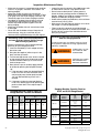
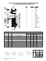
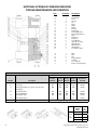
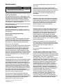
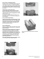
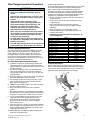
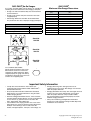
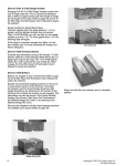
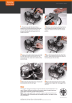
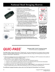
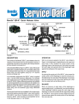
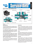
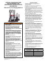
NATIONAL SWAGING MACHINE
AND DIE WARNING, USE,
MAINTENANCE AND APPLICATION
INFORMATION
National Four Post Swaging Machine
WARNING
• Misuse of swaging machine can result in serious
injury or death.
• READ, UNDERSTAND, AND FOLLOW all the
information in this warning document and
the instructions shown in “Wire Rope End
Terminations User’s Manual” before operating the
swaging machine.
• Swaging machine operators must be trained in
accordance with the information supplied by The
Crosby Group LLC. THE SWAGING MACHINE
OWNER IS RESPONSIBLE FOR THE TRAINING
AND THE SAFE OPERATION OF THE SWAGING
MACHINE.
• Do not swage oversize parts.
• Only swage parts of the proper design, material
and hardness.
• If misused, dies and/or die holders may break.
PROTECT YOURSELF AND OTHERS:Always stay
away from the sides of the swaging machine
during swaging operations and alert others in your
work area.
• Do not shim between dies.
• Do not shim die or die holder unless swaging
aluminum sleeves.
• Do not use die holders that are damaged or have
loose side rails or side plates.
• Tie rod nuts must be secured to the tie rods with a
secondary retention system.
• Keep head, hands, and body away from moving
swaging machine and die parts.
• Consult die manufacturer for correct use of
their product.
• Adjust swaging machine tonnage to the Working
Load Limit (WLL) tonnage shown on the die block
being used. If the Working Load Limit is not legible,
refer to Die height & width and corresponding
Working Load Limit (See Table 1). Failure to do so
can result in serious injury or death.
Copyright © 2013 The Crosby Group LLC
All Rights Reserved
Operation Safety
• NEVER use dies that are cracked, worn or
abraded (galled).
• NEVER use dies that have an oversized cavity.
• ALWAYS use a matched set of dies.
• When swaging steel fittings,DO NOT SHIM DIES.
Dies for steel fittings must be free to float and align
one to the other.
• When swaging aluminum fittings, THE STEEL DIES
MUST BE SHIMMED. Shim the side of the die to
ensure the proper cavity alignment for flash removal.
• NEVER shim between the dies.
• When Swaging Crosby National fittings, use only
the proper capacity swaging machine for the size
of fitting used (See Swaging Capacity Chart). If the
swaging machine capacity exceeds the die block
Working Load Limit rating, adjust the swaging
machine tonnage to the Working Load Limit shown
on the die block being used. See Table 1 for die
block Working Load Limit.
• Always use the correct size and type of die for the
size wire rope fitting used.
• Make sure that the manufacturer’s die retention
locking pin, bolt, or other device is engaged and has
secured the die before swaging. Make sure that the
dies are straight, parallel, and perpendicular to each
other before and during the swaging procedure.
• Always lubricate die faces and cavities with light
weight oil.
• Progressive swaging of fittings must be done in
accordance with procedure shown in “Wire Rope
End Terminations User’s Manual”. Only open
channel dies are to be used.
• Stop swaging when the cavity side of both dies
touch. Observe the die closure from above and
slightly to the side. The best position is to stand 45
degrees to either side of the front.
• Make sure part is swaged to the recommended after
swage dimensions (See Crosby General Catalog or
“Wire Rope End Terminations User’s Manual”, Die
Guide, or Die Chart).
• If a swage fitting other than a Crosby National is
used, determine adequacy of the termination by a
destructive pull test.
• All swage sockets must be swaged with socket head
adjacent to the socket relief (largest radius) on
the die.
• For special applications or conditions, contact
Crosby National (501)962-3112.
TABLE 1
Die Size
(Height x Width)
2” x 3-1/2”
2-1/2” x 4”
2-1/2” x 5”
4” x 7”
5” x 7”
6” x 12”
Working Load Limit
(WLL)*
200 Ton Mark Series
200 Ton National
500 Ton Mark Series
1,200 Ton Mark Series
1,500 Ton National
3,000 Ton National
* Note: These Working Load Limits are for Crosby® National Die Blocks only.
The Working Load Limits of die blocks from other manufacturers may vary.
65
Inspection Maintenance Safety
• Make sure the swager is in good operating condition
and that all gauges, indicators and controls are
working properly.
• Make sure all bolts and nuts are in place and
tightened to recommended torque as shown in Table
A, on page 13 for new style swaging machines, and
Table B on page 14 for current swaging machines.
• Load block or die base plate surfaces must be to
manufacturers specifications for thickness and
flatness to provide complete support of the die
during swaging.
• Make sure die holder side rails are not bent, loose
or damaged.
• Clean dies and die holder surfaces. Keep free of
metal shavings, slag, grit, sand, floor dry, etc.
• Lubricate the four guide bushings daily with light oil.
Die Working Load Limit Pressure Adjustment
on Lower Cylinder National 500 Ton through
1500 Ton Swaging Machines
Follow this procedure to adjust swaging tonnage
(pressure) on your swaging machine.
1. Install the die holder(s) or die adapter with the
dies to be used.
2. Bring the dies together (without a part in the
dies) until they just touch.
3. Turn the tonnage control valve, which is located
on the control panel left of the tonnage gauge,
counter-clockwise about (6) six turns or until
knob no longer turns.
4. Now (without a part in the dies) apply pressure
to the dies by pressing the foot pedal marked
“up”.
A. If the tonnage is lower than desired Working
Load Limit, turn the valve clockwise while
continuing to press the foot pedal marked
“up” until desired Working Load Limit is
reached.
B. If tonnage is higher than desired Working
Load Limit, release pressure by pressing the
pedal marked “down”. Then repeat steps 2
through 4.
500 Ton
Largest Fitting Allowed to be Swaged
(in.)*
Swaging
Method
Full Die
Die Size
(in.)
S-505
Sleeve
Mark
Series
2-1/2 x 5
4x5
5x7
1-1/2
S-506
Sleeve
1-1/4*
S-510
Ferrules
9/16*
S-409
Buttons
7/8*
1000 Ton
Full Die
4x7
5x7
2-1/2
1-1/4*
9/16*
1-1/4*
1500 Ton
Full Die
5x7
6 x 12
3-1/2
1-1/4*
9/16*
1-1/4*
6 x 12
4-1/2
3000 Ton
Full Die
1-1/4*
9/16*
Die Working Load Limit Pressure Adjustment on
3000 Ton Swaging Machine
For reducing tonnage, use selector switch on front of
control panel to select lower tonnage (approximately
1500 Tons) or 3000 Ton.
WARNING
ALWAYS USE 5 X 7 OR
6 X 12 DIES AT 1500
TON SETTING.
WARNING
USE ONLY 6 X 12 DIES
ON TONNAGE THAT
EXCEEDS 1500 TONS.
Swaging Machine Capacity Chart for
S-501 and S-502 Swage Socket
Swaging Machine Capacity Chart for
Swage Sleeves, Ferrules and Buttons
Hydraulic
Swaging
Machine
Size
• Inspect the rods for corrosion. Use #000 emery cloth
or steel wool to maintain a high polish surface.
• Do not increase the hydraulic system pressure
above the factory preset pressure of: 6500 psi for
500 ton, 1000 ton and 1500 ton swaging machines –
5000 psi for 3000 ton swaging machine.
• Under ordinary operating conditions, drain and clean
reservoir every two (2) years.
• Make certain that the hydraulic reservoir is full when
the swager is in the full open position.
• Filters inside of the reservoir should be cleaned
every time the reservoir is drained and cleaned. The
Racine “tell-tale” suction filter should be cleaned
every six (6) months.
1-1/4*
Hydraulic
Swaging
Machine
Size
Swaging
Method
Mark Series
2-1/2 x 5
4x7
5x7
3/4
Progressive
4x7
5x7
1-1/4
Full Shank
4x7
5x7
1
Progressive
4x7
1-1/2
Full Shank
5x7
6 x 12
1-1/4
Progressive
5x7
6 x 12
2
Full Shank
6 x 12
2
Progressive
6 x 12
2-1/2
1500 Tons
* Largest size fitting available.
3000 Tons
Largest Fitting
Allowed to be
Swaged
(in.)*
Full Shank
500 Tons
1000 Tons
Die
Size
(in.)
* Largest size fitting available.
66
Copyright © 2013 The Crosby Group LLC
All Rights Reserved
“NEW STYLE” NATIONAL HYDRAULIC SWAGING MACHINE
TORQUE MAINTENANCE INFORMATION
Item
No. Req’d.
A
B
C
D
E
F
G
H
J
K
L
M
N
P
Q
R
S
T
U
V
W
X
Y
Z
AA
1
1
1
4
8
1
2
1
4
1
1
2
2
2
2
2
1
1
4
1
4
2
2
2
1
Description
Cylinder
Housing Cap
Piston
Tie Rod
Tie Rod Nut
Platen
Guide
Gland
Bushing
Mono Seal
Seal Spacer
Side Cylinder
Side Cylinder Mount
Lower Bracket
Knuckle
Upper Bracket
Check Valve
Check Valve Seal
Tie Rod Eyebolt
Cap Eyebolt
Key
Bumper
Bumper Strip
Rubber Skirt
Bottom of Seal Cavity
Table B
Torque in Ft-Lbs
Item No.
No.
Req’d.
1
Varies
Description
Tie Rod Nut Jack-Bolts
500 Ton
Swaging
Machine
1000 Ton
Swaging
Machine
1500 Ton
Swaging
Machine
Maintenance
Schedule
105
N/A
260
Weekly
2
4
Check Valve Bolts
100
100
100
Weekly
3
8
Lower Bracket Bolts
100
100
100
Weekly
4
8
Upper Bracket Bolts
100
100
100
Weekly
5
4
Guide Bolts
250
250
250
Weekly
6
8
Bushing Screws
15
15
15
Weekly
7
4
Key Screws
4
4
4
Weekly
525
600
700
Monthly
4
4
4
Monthly
700
800
800
Monthly
8
4
Platen Bolts
9
6
Bumper Apron Screws
10
12
Gland Bolts
Bolt Size
Thread
Form
Die
Holder
Bolt
Torque
Copyright © 2013 The Crosby Group LLC
All Rights Reserved
Torque
in
ft./ lbs.
1/4 20 UNC
13
5/16 18 UNC
15
5/8 11 UNC
211
7/8 9 UNC
583
67
NATIONAL HYDRAULIC SWAGING MACHINE
TORQUE MAINTENANCE INFORMATION
Item
No. Req’d.
1
2
3
4
5
6
7
8
9
10
11
12
13
14
15
16
17
18
19
20
21
1
1
1
4
8
1
2
1
4
1
12
4
12
4
4
2
1
2
8
2
1
Description
Cylinder
Housing Cap
Piston
Tie Rod
Nut
Platen
Guide
Gland
Bushing
Packing Set
Packing Gland Nut
Packing Gland Spacer
Stud
Cap Screw
Cap Screw
Lower Bracket
Upper Bronze Ring
Upper Bracket
Machine Screw
Side Cylinder
Lower Bronze Ring
A
B
C
D
E
X
Y
1
4
4
1
4
1
1
Block
Stud
Nut
Copper “O” Ring
Lock Nut
Top of Cylinder
Bottom of Packing Cavity
Table A
Torque in Ft. Lbs.
Item No.
Description
500 Ton
Swaging
Machine
800 Ton 1000 Ton
Swaging Swaging
Machine Machine
1500 Ton
Swaging
Machine
Maintenance
Schedule
5
Tie Rod Nuts
2000
2250
2500
2500
Weekly
14
Piston Bolts
525
600
600
700
Monthly
11
Packing Gland Nuts (over spacers only) “all others
hand tighten”
200
200
200
200
Weekly
15
Platen Guide Bolts
250
250
250
250
Weekly
13
Packing Gland Bolts
Side Cylinder Bolts
700
100
800
N/A
800
100
800
150
6 Months
Weekly
19
Guide Bushing Bolts
15
15
15
15
Weekly
80 M Piston Pump Pistons
96 to 125 all Swaging Machines
Bolt Size
Thread
Form
Die
Holder
Bolt
Torque
68
Torque
in
ft./ lbs.
1/4 20 UNC
13
5/16 18 UNC
15
5/8 11 UNC
211
7/8 9 UNC
583
Copyright © 2013 The Crosby Group LLC
All Rights Reserved
Die Information
CAUTION
• Improper die selection could result in significant
loss of efficiency in the termination.
National dies and die holders are made solely for
swaging properly designed fittings on wire rope, and any
other uses are prohibited.
The swaging operation results in a high degree of cold
metal flow. The movement that occurs between the fitting
and the dies will cause wear of the dies. Therefore,
to prolong the life of the dies, it is important to always
lubricate die faces and cavities between each pass with
a light weight oil or high pressure grease.
When scores appear in the die cavities, the dies should
be removed from service.
NEVER EXCEED THE WORKING LOAD LIMIT OF
DIES OR DIE HOLDERS.
All National Standard dies 1/4” through 1” include an
open channel die cavity and a tapered die cavity in the
same die block.
Dies for S-505 Standard Steel Sleeves
(Flemish Eyes)
Die sizes for 1/4” through 1”
Swaging 1/4” through 1” Standard Steel S-505 sleeves
on Flemish Eye terminations requires the use of the
taper cavity only. Refer to page 24 of the Wire Rope End
Termination User’s Manual for proper die selection.
Die sizes for 1-1/8” and above
Swaging 1-1/8” and larger Standard Steel S-505 sleeves
on Flemish Eye terminations requires using 2 sets of
open channel dies (1st stage and 2nd stage) for each
size. Beginning with the 1st stage die and finishing
with the 2nd stage die will achieve proper after swage
dimensions. Dies for S-505 Sleeves 1-1/8” and larger are
single cavity with open channel. Refer to page 24 of the
Wire Rope End Termination User’s Manual for proper
die selection.
Using S-505 Sleeves with Metric Ropes
Although Crosby National S-505 Standard Steel sleeves
are designed to be used with most metric ropes, there
are selected “intermediate” sizes of metric ropes that
when swaged in standard National dies utilizing Crosby
National S-505 sleeves do not achieve required after
swage dimensions and efficiencies. To ensure all 505
sleeves achieve the required efficiency when used with
metric ropes, Crosby provides special National swaging
dies to be used in conjunction with selected size
metric ropes. These new dies will produce the required
efficiencies and after swage dimensions.
The table found on Page 25 of the Wire Rope End
Termination User’s Manual identifies the new dies that
are required to properly swage the selected intermediate
size wire ropes not covered in the standard product
offering found on Page 24 of the manual.
Copyright © 2013 The Crosby Group LLC
All Rights Reserved
Dies for 6mm through 26mm (except 12mm, 20mm
and 24mm)
Swaging on 6mm through 26mm metric ropes for
Flemish Eye slings requires the selection of the proper
S-505 Standard Steel sleeve and the use of the tapered
cavity only. Refer to page 24 of the Wire Rope End
Termination User’s Manual for proper sleeve and
die selection.
Dies for 12mm, 20mm and 24mm
Swaging on 12mm, 20mm and 24mm metric ropes for
Flemish Eye slings requires the selection of the proper
S-505 Standard Steel sleeve and the use of both the
open cavity and tapered cavity in special dies. Refer
to page 25 of the Wire Rope End Termination User’s
Manual for proper sleeve and die selection.
Dies for 28mm and larger
Swaging on 28mm and larger metric ropes for Flemish
Eye slings requires the selection of the proper S-505
Standard Steel sleeve and the use of 2 sets of open
channel dies (1st stage and 2nd stage) for each size.
Beginning with the 1st stage die and finishing with
the 2nd stage die will achieve proper after swage
dimensions. Dies for S-505 sleeves 28mm and larger
are single cavity with open channel. Refer to page 24 of
the Wire Rope End Termination User’s Manual for proper
sleeve and die selection.
Important: If the specific size metric rope required is
not listed on page 24 of the Wire Rope End Termination
User’s Manual refer to Intermediate Metric Die Chart on
page 25 of the manual for proper sleeve and
die selection.
Dies for QUIC-PASS® Swaging System – 1/4”
through 1-1/2”
The QUIC-PASS® swaging system allows “Flemish
style” wire rope terminations to be swaged in only two
passes. This is accomplished while maintaining currently
published efficiency ratings and utilizing National Swage
S-505 Standard “COLD TUFF”® Steel Sleeves.
The special design of the QUIC-PASS® dies allows the
swaging process to be completed in just two passes,
resulting in a 50-75% reduction in the number of passes
required with conventional swaging systems. Unlike
standard round dies, the QUIC-PASS® dies close
completely with each pass, resulting in an increase in
overall swaging process efficiencies (the job can be
performed quicker), a reduction in the complexity of
swaging (the concern for excess flashing between dies
has been eliminated) and a reduction in training time
needed for operators (more user friendly).
The finished sleeve has a “Hex” appearance that
provides a QUIC-CHECK® look to determine if the
termination has been swaged and provides a flat
surface that allows for ease of I.D. stamping on the
finished sleeve. Refer to page 24 of the Wire Rope End
Termination User’s Manual for proper die selection.
69
Dies for S-501 & S-502 Swage Sockets
Swaging all S-501 & S-502 Swage Sockets requires the
use of single cavity die. This is a special die designed
with a relief for swage sockets and extra length to swage
the full length of the shank. Refer to pages 36 and 37 of
the Wire Rope End Termination User’s Manual for proper
die selection.
Swage Sockets for Spiral Strand Rope
Our tests indicate that if the spiral strand is 1 x 19 or
greater, and the ultimate strength does not exceed
Table 4 of ASTM A586, you can use dies for size swage
sockets up to the 1-1/4”. For sizes greater than 1-1/4” the
following table will apply:
If the strand is of greater strength than Table 4 or has
less metallic area, we must recalculate the design and
test for adequacy.
Two Cavity Die
Dies for S-506 Turnback Sleeves
Turnback eye terminations using 5/16” through 1” S-506
Sleeves utilize the S-505 Standard Steel Sleeve die (1st
Stage open channel die only). The 1-1/4” S-506 Sleeve
utilizes the 1-3/8” socket (S-501 and S-502) die. Refer
to page 46 of the Wire Rope End Termination User’s
Manual for proper die selection.
Dies for S-409 Buttons
Buttons are swaged in open channel dies. Refer to page
42 of the Wire Rope End Termination User’s Manual for
proper die selection.
Specific recommended swaging practices can be found
in each product section of this brochure. The proper
die selection and the recommended maximum after
swage dimensions are referenced in the section of this
brochure that contains the product you are swaging. This
information can also be found in The Crosby General
Catalog (See Section “Wire Rope End Terminations”),
the National Swage Die Guide, or by referring to the
National Swage Die Chart.
Dies and die adapters to fit other type swaging machines
are available upon request (Refer to page 19).
Never use dies that are cracked, worn or abraded
(galled).
Single Cavity Die
70
Copyright © 2013 The Crosby Group LLC
All Rights Reserved
After Swage Inspection Procedures
WARNING
• Read, understand, and follow these instructions
before using the National QUIC-PASS® Swaging
System.
• Improper after swage dimensions can result in sling
failure resulting in property damage, serious injury
or death.
• Always gauge or measure the after swage
dimensions to ensure proper sling performance.
• Using National Swaging System with ropes and
termination styles other than shown in these
procedures may reduce the performance of the
termination and lead to premature failure.
• When using rope constructions other than shown in
this procedure, the termination must be destructive
tested and documented to prove adequacy of the
assembly to be manufactured.
• The QUIC-PASS® Swaging System is designed only
for “Flemish Eye” terminations using National S-505
Standard Steel Sleeves.
• The QUIC-PASS® Swaging System is not designed for
Cable-Laid wire rope slings or fiber core wire rope.
Checking Swaging Dimensions
One of the important considerations in producing a quality
termination is the overall diameter of the fitting after the
swaging process is complete. Since all dies wear, and
the swaged fitting used in terminations have spring back,
the results of swaging should be checked periodically to
determine the wear condition of the die as well as to ensure
the fitting is swaged to proper dimensions.
Key Facts About After Swage Dimensions:
1. In addition to worn dies, not achieving the proper after
swage dimension can also be due to the die not being
fully closed during swaging. Dies showing excessive wear
should be replaced.
2. The effective swaging that dies can accomplish stops
when the die lands touch each other. Any continued
swaging adds needless wear and strain on the dies and
swaging machine.
3. By placing a light oil on the die faces and in the cavity, the
dies will be lubricated as well as protected.
4. The oozing of the oil from the faces of the dies as they
touch will indicate when the dies have closed. At this
point, stop the swaging cycle.
5. Additional swaging adds needless wear and strain to the
dies and swaging machine.
6. Never use dies that are cracked, worn or abraded
(galled).
7. The Crosby Group does not recommend the checking of
die dimensions as an acceptable method of determining
the quality of a swage sleeve, button, ferrule, or socket.
8. It is our recommendation that the checking of the after
swage dimension of the swaged fitting is the most
accurate indicator of a properly swaged termination.
Measuring the die cavity only is not an acceptable
process control check.
9. If the die cavity wears, the dies are not closed completely
during swaging. If an inadequate number of presses are
used, it could be quickly identified by checking the after
swage dimension of the part.
10.Swaging Machine not producing sufficient tonnage will
affect after swage dimensions.
Copyright © 2013 The Crosby Group LLC
All Rights Reserved
No-Go Gauge Information
To assist in checking the after swage dimensions of the fitting,
the Crosby Group provides the National No-Go Gauges.
When used correctly the National No-Go Gauges can
determine if the fittings were swaged to the proper diameter.
We would recommend that all Crosby products or product
swaged in Crosby dies be checked with the proper gauge to
determine the acceptability of the swaging process.
• Gauges are made of hardened alloy steel and machined
to strict tolerances.
• Gauge can be used to verify that all fittings have been
swaged properly.
• After swage dimensions not within the maximum
limits may result from worn dies or improper swaging
techniques.
• Other type gauges are available upon request.
• National No-Go Gauges are available for a variety of
products (See Table 1).
• No-Go Gauges and QUIC-PASS® No-Go Gauges are
not interchangeable.
Table 1
Fitting and Size
505 Sleeve 1/4 - 7/8
505 Sleeve 1 - 1-1/2
505 Sleeve 1-3/4
505 Sleeve 2
505 Sleeve 2-1/4
505 Sleeve 2-1/2
505 Sleeve 2-3/4
505 Sleeve 3
505 Sleeve 3-1/2
505 Sleeve 3-3/4
505 Sleeve 4
501/502 Socket 1/4 - 1
501/502 Socket 1-1/8 - 1-3/4
501/502 Socket 2
Part No.
1095512
1095521
1095530
1095549
1095558
1095587
1095576
1095565
1095594
1095601
1095610
1095647
1095656
1095665
Using No-Go Gauges
When swaged properly, the gauge will go up and down (see
Figure 1) and around the full length of the fitting (see Figure 2).
For the proper after swage dimensions, see the section in this
publication for the specific product you are swaging.
Figure 1
Figure 2
71
QUIC-PASS® No-Go Gauges
As a further aid, QUIC-PASS® No-Go gauges are available for
checking the sleeve’s dimensions after swaging is complete.
• Gauges are made of hardened alloy steel and machined
to strict tolerances.
• Gauge can be used to verify that all sleeves have been
swaged properly.
• “After Swage” dimensions not within the maximum limits
may result from worn dies or improper swaging techniques.
QUIC-PASS® No-Go Gauges
Sleeve and Size
No-Go Gauge for S-505 1/4” - 7/8”
No-Go Gauge for S-505 1” - 1-1/4”
No-Go Gauge for S-505 1-3/8” - 1-1/2”
Stock No.
1923705
1923712
1923714
QUIC-PASS®
Maximum After Swage Dimensions
Size
(in.)
1/4
5/16 - 3/8
7/16 - 1/2
9/16 - 5/8
3/4
7/8
1
1-1/8
1-1/4
1-3/8
1-1/2
Maximum “After Swage” Dimension
(in.)
0.565
0.769
1.016
1.247
1.475
1.738
1.955
2.170
2.405
2.610
2.835
Stock No.
1923705
Stock No.
1923712
Stock No.
1923714
Use a National QUIC-PASS®
No-Go Gauge to check the after swage
dimensions to ensure that it has been
swaged to the proper dimension. When
swaged properly, the gauge will slide up
and down the full length of the sleeve on
all three sets of opposing flats.
1
3
2
2
3
1
Important Safety Information
• Crosby does not recommend a “Texas Tuck” style
termination with Crosby National S-505 “COLD TUFF®”
Standard Steel Sleeves.
• Only Crosby National S-505 “COLD TUFF®” Standard
Steel Sleeves are recommended when using the QUICPASS® Swaging System.
• National S-505 Standard Steel Sleeves, when used with
the QUIC-PASS® Swaging System, are only recommended
for use with one (1) part 6 X 19 or 6 X 37, IPS or XIP
(EIP), XXIP (EEIP), RRL, IWRC rope.
• The condition of the swaging machine can cause sleeve
“After Swage” size not to be within the proper dimensions.
Example: worn bushings, loose tie rods, loose die
holders, misaligned platens, worn pins, worn linkage, etc.
72
• Swaging dies being worn, damaged, misused, or
undersized can cause sleeve “After Swage” size not to be
within the proper dimension.
• Swaging die holders excessively worn, damaged, misused
or loose can cause sleeve “After Swage” size not to be
within the proper dimension. Only use QUIC-PASS®
dies and die holders inspected and properly secured in
National swaging machines.
• Always refer to Warning and Application information
found in the Crosby General Catalog and Wire Rope End
Terminations User’s Manual.
Copyright © 2013 The Crosby Group LLC
All Rights Reserved