1
GE Infrastructure
Sensing
Instrument Data Manager
User’s Manual
GE Infrastructure
Sensing
Instrument Data Manager
User’s Manual
910-185D
October 2004
October 2004
END USER LICENSE AGREEMENT
[INSTRUMENT DATA MANAGER SOFTWARE]
YOU MUST READ AND ACCEPT ALL TERMS AND CONDITIONS OF THIS
AGREEMENT BEFORE USING THIS SOFTWARE. GE INFRASTRUCTURE SENSING,
INC. ("LICENSOR") AGREES TO LICENSE THE SOFTWARE TO YOUR COMPANY
("LICENSEE") ONLY UNDER THE TERMS OF THIS AGREEMENT. IF YOU DO NOT
AGREE TO THESE TERMS, PROMPTLY RETURN THE CD, DOCUMENTATION AND
ALL OTHER COMPONENTS OF THE SOFTWARE TO THE LICENSOR AND/OR
PERMANENTLY DELETE ALL ELECTRONIC FILES RELATED THERETO TO RECEIVE
A REFUND OF LICENSE FEES PAID.
1. DEFINITIONS.
1.1 "Documentation" shall mean any
Licensor user manuals and other printed
materials delivered to Licensee in
conjunction with the Programs.
1.2 "Intellectual Property Rights" shall
mean patent rights (including patent
applications and disclosures), copyrights,
moral rights, trademark/service mark
rights, trade dress rights, trade secrets,
know-how and any other intellectual
property rights recognized in any country
or jurisdiction in the world.
1.3 "Programs" shall mean the
PanaView computer software program
referenced above, including all
modifications, enhancements, and
revisions thereto that are either: (i)
expressly authorized by Licensor in
writing; or (ii) created by Licensor
pursuant to a software support agreement
between the parties, if any.
2. LICENSE.
2.1 License Grant. Subject to the terms
of this Agreement, Licensor grants
Licensee a perpetual, non-transferable,
non-exclusive license to install the
Program on one personal computer and
use the Programs and Documentation to
support any number or combination of
GE Infrastructure Sensing instruments
networked on the one personal computer.
Licensee may make one additional copy
of the Programs and Documentation
solely for archival purposes.
2.2 License Restrictions. All Programs
are licensed and not sold. Except as
otherwise expressly provided in this
Agreement, Licensee shall not make any
copies of the Products or Documentation,
and shall not decompile, disassemble,
decrypt, extract or otherwise reverse
engineer the Products. Any
modifications, revisions, changes or
enhancements made by Licensee to the
Products or Documentation without
Licensor's express prior written
permission shall be deemed a material
breach of this Agreement, and any
End User License Agreement
Intellectual Property Rights created
without permission shall become
Licensor's sole property without any
additional Licensor action necessary to
perfect its ownership rights and interests.
Notwithstanding anything to the contrary
in this Agreement, all rights, title and
ownership of any such modifications,
revisions, changes and enhancements
shall reside solely in Licensor. Except as
expressly provided in Section 11.1,
Assignment, the Programs shall not be
sold, leased, assigned, transferred,
distributed or sublicensed, in whole or in
part. Licensee shall not delete or in any
manner alter copyright, trademark or
other proprietary rights notices of
Licensor or its suppliers appearing on the
Programs and Documentation.
3. TAXES. Licensee shall, in addition
to any license payments required
hereunder, pay all applicable sales, use,
transfer, value-added or other taxes and
all duties, whether international, national,
state or local, however designated, which
are levied or imposed by reason of the
transaction(s) contemplated hereby,
excluding only income taxes on net
profits which may be levied against
Licensor. Licensee shall reimburse
Licensor for the amount of any such taxes
or duties paid or accrued directly by
Licensor as a result of said transaction(s).
If Licensee is prohibited by law from
making payments hereunder free of such
deductions or withholdings, Licensee
shall immediately notify Licensor and
pay Licensor any additional sum(s) equal
to such deduction or withholding.
4. WARRANTIES.
4.1 Limited Program Warranty.
Licensor warrants that the media on
which the Products are distributed shall
be free from defects for a period of ninety
(90) days after delivery. As Licensee's
sole and exclusive remedy and Licensor's
entire liability for any breach of this
warranty, Licensor shall, at its sole
option: (i) repair or replace, at no
additional charge to Licensee, any
i
October 2004
defective media; or (ii) if, despite using
its reasonable efforts, Licensor is unable
to replace the media, refund to Licensee
the applicable license fees paid for the
non-conforming media after Licensee
returns the media to Licensor, less a
reasonable license fee for the period
during which Licensee had use of the
Program, using straight-line depreciation
assuming a useful life of the Program of
three (3) years. The limited warranty set
forth herein shall automatically become
null and void if a party other than
Licensor modifies the Programs in any
way.
4.2 Disclaimer Of Warranties.
EXCEPT FOR THE EXPRESS MEDIA
WARRANTY ABOVE, THE
PROGRAMS AND DOCUMENTATION
ARE PROVIDED "AS-IS", WITH ALL
FAULTS. LICENSOR MAKES NO
OTHER WARRANTIES OF ANY
KIND, EITHER EXPRESS OR
IMPLIED. LICENSOR EXPRESSLY
DISCLAIMS ANY AND ALL OTHER
WARRANTIES, INCLUDING BUT
NOT LIMITED TO, ANY IMPLIED
WARRANTIES OF NONINFRINGEMENT AND THE IMPLIED
WARRANTIES OF
MERCHANTABILITY AND FITNESS
FOR A PARTICULAR PURPOSE.
LICENSOR DOES NOT WARRANT
THAT THE PROGRAMS SHALL BE
ERROR-FREE OR THAT THEY
SHALL FUNCTION WITHOUT
INTERRUPTION.
4.3 Excluded Uses. UNLESS
EXPRESSLY PROVIDED IN A
SEPARATE WRITTEN AGREEMENT,
THE SOFTWARE MAY NOT BE USED
AS ON-LINE CONTROL EQUIPMENT
IN HAZARDOUS ENVIRONMENTS
REQUIRING FAIL-SAFE
PERFORMANCE, SUCH AS IN THE
OPERATION OF NUCLEAR
FACILITIES, AIRCRAFT
NAVIGATION OR COMMUNICATION
SYSTEMS, AIR TRAFFIC CONTROL,
DIRECT LIFE SUPPORT MACHINES,
OR WEAPONS SYSTEMS, IN WHICH
THE FAILURE OF THE SOFTWARE
COULD LEAD DIRECTLY TO DEATH,
PERSONAL INJURY, OR SEVERE
PHYSICAL OR ENVIRONMENTAL
DAMAGE.
5. LIMITATIONS OF LIABILITY.
5.1 Exclusion of Damages.
WHETHER ANY REMEDY SET
FORTH HEREIN FAILS OF ITS
ESSENTIAL PURPOSE OR
OTHERWISE, IN NO EVENT SHALL
ii
LICENSOR BE LIABLE FOR ANY
SPECIAL, INCIDENTAL, INDIRECT
OR CONSEQUENTIAL LOSS,
LIABILITY OR DAMAGES OF ANY
KIND (INCLUDING BUT NOT
LIMITED TO LOSS OF USE, DATA,
BUSINESS OR PROFITS) WHETHER
ARISING UNDER A THEORY OF
CONTRACT, TORT (INCLUDING
NEGLIGENCE), BREACH OF
WARRANTY, PRODUCT LIABILITY
OR OTHERWISE, AND REGARDLESS
OF WHETHER LICENSOR HAS BEEN
ADVISED OF THE POSSIBILITY OF
SUCH LOSS, LIABILITY OR
DAMAGES.
5.2 Total Liability. IN NO EVENT
SHALL LICENSOR'S CUMULATIVE
LIABILITY ARISING FROM OR
RELATED TO THIS AGREEMENT,
FROM ALL CAUSES OF ACTION OF
ANY KIND, WHETHER ARISING
UNDER A THEORY OF CONTRACT,
TORT (INCLUDING NEGLIGENCE),
BREACH OF WARRANTY, PRODUCT
LIABILITY OR OTHERWISE,
EXCEED THE TOTAL AMOUNT OF
LICENSE FEES ACTUALLY
RECEIVED BY LICENSOR FROM
LICENSEE UNDER THIS
AGREEMENT. SOME STATES OR
JURISDICTIONS DO NOT ALLOW
EXCLUSION OF IMPLIED
WARRANTIES OR LIMITATION OF
INCIDENTAL OR CONSEQUENTIAL
DAMAGES, SO THE ABOVE
LIMITATIONS MAY NOT APPLY TO
YOU.
5.3 Basis of the Bargain. All warranty
disclaimers and liability limitations set in
this Agreement shall apply upon delivery
of the Programs to Licensee. Licensee
acknowledges that Licensor has set its
prices and entered into this Agreement in
reliance upon such disclaimers of
warranty and the limitations of liability
and that the same forms an essential basis
of the bargain between the parties.
6. INDEMNIFICATION. LICENSEE
SHALL INDEMNIFY, DEFEND AND
HOLD LICENSOR HARMLESS FROM
AND AGAINST ALL CLAIMS,
LIABILITIES, ACTIONS, SUITS,
DEMANDS, FINES, PENALTIES AND
ALL COSTS AND EXPENSES
INCURRED BY LICENSOR IN
CONNECTION THEREWITH
(INCLUDING REASONABLE
ATTORNEYS' FEES) ARISING OUT
OF OR RELATED TO: (A) LICENSEE'S
USE OF THE PROGRAMS IN
COMBINATION WITH SOFTWARE
End User License Agreement
October 2004
OR HARDWARE NOT SPECIFICALLY
APPROVED BY LICENSOR IN
WRITING; (B) LICENSOR'S
COMPLIANCE WITH DESIGNS OR
SPECIFICATIONS PROVIDED BY
LICENSEE; (C) ANY MODIFICATION,
ENHANCEMENT OR REVISION
MADE TO THE PROGRAMS BY
ANYONE OTHER THAN LICENSOR;
OR (D) LICENSEE'S FAILURE TO USE
ANY MODIFICATION,
ENHANCEMENT OR REVISION
PROVIDED TO LICENSEE BY
LICENSOR FOR THE PURPOSE OF
AVOIDING A CLAIM OF
INFRINGEMENT.
7. TERMINATION.
7.1 Termination for Breach. Either
party may terminate this Agreement with
respect to one or all of the Programs in
the event of a breach or default by the
other party; provided, however, no such
termination shall occur until the nonbreaching/defaulting party shall have
given written notice of the breach or
default to the breaching/defaulting party
and such breach or default shall not have
been cured within five (5) days in the
event of a monetary breach or default and
thirty (30) days in the event of a nonmonetary breach or default.
7.2 Automatic Termination. This
Agreement shall terminate automatically
if: (i) either party becomes the subject of
any voluntary or involuntary petition in
bankruptcy or any proceeding relating to
insolvency, receivership, liquidation or
composition for the benefit of creditors,
and in the case of an involuntary petition
or proceeding such petition or proceeding
is not dismissed within sixty (60) days of
filing; or (ii) Licensee fails to pay license
fees when due or commits a material
breach of the license provisions in
paragraph 2 above.
7.3 Effect of Termination. Upon any
termination of this Agreement or of any
individual Program license, Licensee
shall promptly return to Licensor or, at
Licensor's election, destroy the applicable
Programs and Documentation and all
copies and portions thereof, in all forms
and types of media related thereto, and
provide Licensor with an written
certification signed by a duly authorized
representative of Licensee, certifying to
Licensee's compliance with the
foregoing. Licensee's exclusive remedy
for breach shall be the return of all license
fees received by Licensor related to the
affected Programs.
End User License Agreement
7.4 Non-exclusive Remedy. Except as
provided otherwise in this Agreement, all
remedies of either party shall be nonexclusive and shall be without prejudice
to any other right or remedy of such party.
8. SURVIVAL. All provisions of this
Agreement relating to liability,
warranties, indemnities or confidentiality,
and the provisions of Sections 7, 10 and
11 of this Agreement, shall survive the
expiration or termination of this
Agreement.
9. GOVERNING LAW. This
Agreement will be governed by and
construed in accordance with the
substantive laws in force: a) in the State
of New York excluding its conflict of
laws rules if this license is purchased
when you are in the United States,
Canada or Mexico; or b) in Japan if this
license is purchased when you are in
Japan, China, Korea, R.O.C. or another
Southeast Asian country where all official
languages are written in either an
ideographic script (e.g. hanzi, kanji or
hanja), an/or other script based upon or
similar in structure to an ideographic
script; or c) the Netherlands if this license
is purchased when you are in any other
jurisdiction not described above. The
respective courts of New York, Tokyo
and Amsterdam as applicable hereunder
shall each have non-exclusive jurisdiction
over all disputes relating to this
Agreement. This Agreement will not be
governed by the conflict of laws rules of
any jurisdiction or the United Nations
Convention on Contracts for the
international Sale of Goods, the
application of which is expressly
excluded.
10. INJUNCTIVE RELIEF. If Licensee
breaches, or threatens breach of any part
of this Agreement, Licensee
acknowledges and agrees that Licensor
will be greatly damaged, and such
breach(es) will be irreparable and
damages associated therewith will be
difficult to quantify; therefore, Licensor
may apply to any court of competent
jurisdiction, who, notwithstanding the
Governing Law provisions above, will
apply the laws of its own jurisdiction in
determining whether relief shall be
granted to Licensor, for injunctive or
other equitable relief to restrain such
breach or threat of breach, without
impairing, invalidating, negating or
voiding Licensor's other rights to relief
either at law or in equity.
iii
October 2004
11. General
11.1 Assignment. Licensee may assign
this entire Agreement with the sale of any
of its GE Infrastructure Sensing
instruments provided that Licensee and
its assignee agrees in writing to comply
with all provisions of this Agreement.
Otherwise, Licensee may not assign this
Agreement without Licensor's prior
written consent. Any other attempted
assignment shall be null and void and
shall automatically terminate this
Agreement.
11.2 Compliance with Laws and Export.
Each party shall comply in all material
respects with all laws, rules, approvals,
registrations and regulations of the
United States and other countries that
may be applicable to the Programs or to
each party's activities under this
Agreement. In addition, you agree that
the Products and Documentation will not
directly or indirectly be shipped,
transferred or exported or re-exported
into any country or used in any manner
prohibited by the United States Export
Administration Act or any other export
laws, restrictions or regulations
(collectively "Export Laws"). If the
Programs are identified as exportcontrolled items under the Export Laws.,
you represent and warrant that you are
not a citizen of or otherwise located
within a U.S.-embargoed nation and that
you are not otherwise prohibited under
the Export Laws from receiving the
Programs or Documentation. All right to
use the Programs and Documentation are
granted on condition that such rights are
forfeited if you fail to comply with the
terms of this Agreement.
11.3 Severability. If any or all of the
covenants hereunder are determined by a
court of competent jurisdiction to be
invalid or unenforceable, by reason that
the breadth of restrictions are too great, or
for any other reason, these covenants
shall be modified and interpreted to
extend over the maximum geographic
area, period of time, range of activities or
other restrictions to which they may be
enforceable.
11.4 Force Majeure. Licensor shall not
be responsible for any failure or delay in
its performance under this Agreement
due to causes beyond its reasonable
control, including but not limited to, labor
disputes, strikes, lockouts, shortages of or
inability to obtain labor, energy, raw
materials or supplies, war, riot, act of God
or governmental action.
iv
11.5 Entire Agreement. This Agreement
is the complete and exclusive agreement
between the parties with respect to the
subject matter hereof, superseding and
replacing any and all prior or
contemporaneous agreements,
communications, and understandings
(both written and oral) regarding such
subject matter. Any waiver, modification
or amendment of any provision of this
Agreement shall be effective only if in
writing and signed by duly authorized
representatives of the parties hereto.
11.6 Attorneys Fees. In the event that
either party resorts to legal action to
enforce its rights under this Agreement,
the prevailing party in such action shall
be entitled to have all costs and expenses
incurred in such action, including courts
costs and reasonable attorneys fees, paid
by the other party.
11.7 Notice to U.S. Government End
Users: The Programs and Documentation
are "Commercial Items" as that term is
defined at 48 C.F.R. § 2.101, consisting
of "Commercial Computer Software" and
"Commercial Computer Software
Documentation", as such terms are used
in 48 C.F.R. § 12.212 or 48 C.F.R. §
227.7202, as applicable. Consistent with
48C.F.R. § 12.212 or 48 C.F.R. §
227.7202-1 through 227.7202-4, as
applicable, the Commercial Computer
Software and Commercial Computer
Software Documentation are licensed to
U.S. Government end users: a) only as
Commercial Items; and b) with only
those rights granted to all other end users
pursuant to the terms and conditions
herein. For U.S. Government end users,
GE Infrastructure Sensing agrees to
comply with all applicable equal
opportunity laws including, if
appropriate, the provisions of Executive
Order 11246 as amended, Section 402 of
the Vietnam Era Veterans Readjustment
Assistance Act of 1974 and Section 503
of the Rehabilitation Act of 1973, as
amended, and the regulations at 41 C.F.R.
Parts 60-1 through 60-60,
60-250 and 60-741. The affirmative
action clause and regulations contained in
the preceding sentence shall be
incorporated by reference in this
Agreement.
End User License Agreement
October 2004
Table of Contents
Chapter 1: Features & Capabilities
Basic Features . . . . . . . . . . . . . . . . . . . . . . . . . . . . . . . . . . . . . . . . . . . 1-1
Capabilities. . . . . . . . . . . . . . . . . . . . . . . . . . . . . . . . . . . . . . . . . . . . . . 1-1
Chapter 2: Installation
Personal Computer Requirements . . . . . . . . . . . . . . . . . . . . . . . . 2-1
Software Installation . . . . . . . . . . . . . . . . . . . . . . . . . . . . . . . . . . . . . 2-2
Installing IDM on MS-DOS Computers . . . . . . . . . . . . . . . . . 2-2
Installing IDM for Windows 95/98/NT . . . . . . . . . . . . . . . . . 2-3
Hardware Installation . . . . . . . . . . . . . . . . . . . . . . . . . . . . . . . . . . . . 2-3
Changing an Instrument’s Network ID Number . . . . . . . . 2-4
Connecting the Instrument to the PC/Network. . . . . . . . . 2-5
Chapter 3: Initial Setup
IDM Start-up. . . . . . . . . . . . . . . . . . . . . . . . . . . . . . . . . . . . . . . . . . . . . 3-1
Running IDM from DOS: . . . . . . . . . . . . . . . . . . . . . . . . . . . . . . 3-1
Running IDM from Windows 95/98/NT . . . . . . . . . . . . . . . . 3-2
Setting Up IDM. . . . . . . . . . . . . . . . . . . . . . . . . . . . . . . . . . . . . . . . . . . 3-3
About IDM . . . . . . . . . . . . . . . . . . . . . . . . . . . . . . . . . . . . . . . . . . . . . . . 3-4
Charts. . . . . . . . . . . . . . . . . . . . . . . . . . . . . . . . . . . . . . . . . . . . . . . . . . . 3-5
Understanding the Parts of a Chart . . . . . . . . . . . . . . . . . . . 3-5
Using the Chart Viewing Options. . . . . . . . . . . . . . . . . . . . . . 3-7
Customizing a Line/Bar Chart. . . . . . . . . . . . . . . . . . . . . . . . . 3-8
How to Print Screens/Charts . . . . . . . . . . . . . . . . . . . . . . . . . . . . 3-11
v
October 2004
Table of Contents (cont.)
Chapter 4: Instrument Setup
Main Menu . . . . . . . . . . . . . . . . . . . . . . . . . . . . . . . . . . . . . . . . . . . . . . 4-1
Global Submenu . . . . . . . . . . . . . . . . . . . . . . . . . . . . . . . . . . . . . . . . . 4-2
Connecting to a New Instrument . . . . . . . . . . . . . . . . . . . . . 4-3
Selecting an Existing Instrument . . . . . . . . . . . . . . . . . . . . . . 4-5
Network Scan for Instruments . . . . . . . . . . . . . . . . . . . . . . . . . . . . 4-6
Using Preferences. . . . . . . . . . . . . . . . . . . . . . . . . . . . . . . . . . . . 4-7
Using Dial Modem . . . . . . . . . . . . . . . . . . . . . . . . . . . . . . . . . . . 4-8
Using Hang Up Modem. . . . . . . . . . . . . . . . . . . . . . . . . . . . . . . 4-9
Exiting . . . . . . . . . . . . . . . . . . . . . . . . . . . . . . . . . . . . . . . . . . . . . . . 4-9
Data Submenu . . . . . . . . . . . . . . . . . . . . . . . . . . . . . . . . . . . . . . . . . 4-10
Viewing a Line Chart or Bar Chart of Log Data . . . . . . . . 4-11
Printing a Table of Logged Data . . . . . . . . . . . . . . . . . . . . . 4-12
Chapter 5: IDM Operation
Instrument Menu . . . . . . . . . . . . . . . . . . . . . . . . . . . . . . . . . . . . . . . . 5-1
System Submenu . . . . . . . . . . . . . . . . . . . . . . . . . . . . . . . . . . . . . . . . 5-2
Reading the Instrument Clock . . . . . . . . . . . . . . . . . . . . . . . . 5-3
Setting the Instrument/PC Clocks . . . . . . . . . . . . . . . . . . . . . 5-4
Printing the Site . . . . . . . . . . . . . . . . . . . . . . . . . . . . . . . . . . . . . . 5-6
Deleting a Stored Site . . . . . . . . . . . . . . . . . . . . . . . . . . . . . . . . 5-7
Clearing the Instrument Totalizers . . . . . . . . . . . . . . . . . . . . 5-8
Erasing a Log from an Instrument . . . . . . . . . . . . . . . . . . . . 5-8
Closing the Connection to an Instrument . . . . . . . . . . . . . . 5-9
vi
October 2004
Table of Contents (cont.)
Chapter 6: Data Handling
Upload/Download Submenu . . . . . . . . . . . . . . . . . . . . . . . . . . . . . 6-1
Uploading a Site to a PC Disk . . . . . . . . . . . . . . . . . . . . . . . . . 6-2
Downloading a Site to an Instrument . . . . . . . . . . . . . . . . . 6-4
Uploading a Log to a PC Disk . . . . . . . . . . . . . . . . . . . . . . . . . 6-5
Using the Edit Functions Submenu . . . . . . . . . . . . . . . . . . . . 6-6
Using the Real Time Sub-Menu . . . . . . . . . . . . . . . . . . . . . . . 6-9
Logging Real Time Data . . . . . . . . . . . . . . . . . . . . . . . . . . . . . . 6-9
Logging Diagnostics . . . . . . . . . . . . . . . . . . . . . . . . . . . . . . . . 6-11
Reading Signal Data . . . . . . . . . . . . . . . . . . . . . . . . . . . . . . . . 6-13
Appendix A: Importing ASCII Files into Microsoft Excel
Appendix B: Frequently Asked Questions
vii
October 2004
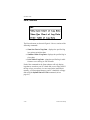
Chapter 1
Features & Capabilities
Instrument Data Manager (IDM) is a software program that
permits interactive communication between a GE Infrastructure
Sensing instrument and a personal computer (PC).
Basic Features
IDM operates on a 16-bit DOS operating system (MS-DOS or
PC-DOS version 3.3 or higher), and it can be run from within a
DOS window that is launched from within Windows 9X or NT.
Capabilities
The following primary tasks may be performed with the
Instrument Data Manager software:
•
save the instrument’s programmed site file data to the hard
drive on the PC.
•
display text output of the live measurement data on the
computer monitor
•
display graphical output of the live measurement data on the
computer monitor.
•
create and save graph and log files to the hard drive on the
computer.
•
save data as an ASCII file for use in a spreadsheet or database
program.
•
interface with multiple GE Infrastructure Sensing instruments.
Features & Capabilities
1-1
October 2004
Chapter 2
Installation
Before beginning the installation, make sure the personal
computer system meets the requirements listed below.
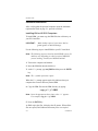
Personal Computer Requirements
IDM requires an Intel 486 processor or better (including laptops).
In addition to a minimum processor speed of 33 MHZ, the PC
must meet the following requirements:
•
RS232 standard serial interface
•
2 MB of RAM (4 MB recommended)
•
Math co-processor (not required, but recommended)
•
At least one high-density disk drive
•
A hard drive with at least 2 MB of free space available for
storing the program, plus adequate space to store site and log
files.
•
A graphics card:
– VGA or equivalent (recommended board)
– Hercules Monochrome Graphics Card or equivalent
•
A mouse (not required, but recommended):
•
Windows 95/98, Windows NT, MS-DOS or PC-DOS version
3.3 or higher
•
A Hewlett Packard PCL-compatible Laser or PostScript®
printer
Installation
2-1
October 2004
Software Installation
After verifying that the personal computer meets the minimum
requirements listed on page 2-1, proceed as follows:
Installing IDM on MS-DOS Computers
To install IDM, you must copy the IDM files into a directory on
your PC’s hard disk.
IMPORTANT:
Make backup copies of your source disk to
guard against accidental damage.
Use the following steps to install IDM on your PC’s hard disk:
Note: The following steps are based on the MS-DOS version 5.0
and may vary depending on which version of MS-DOS
you are running. Consult your MS-DOS manual.
1. Turn on the computer and monitor.
2. Insert the IDM disk into the disk drive.
3. At the C:\> prompt, type md^IDM and then press the ENTER
key.
Note: The ^ symbol represents a space.
When the C:\> prompt appears again, this indicates that your
computer has created a directory named IDM.
4. Copy the IDM files into the IDM directory by typing:
copy^a:*.*^C:\IDM
Note: Insert the appropriate drive letter where “a” appears.
For example, copy^b:*.*^C:\IDM.
5. Press the ENTER key.
As DOS copies the files, it displays the file names. When all the
files are copied, DOS indicates how many files were copied.
2-2
Installation
October 2004
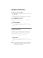
Installing IDM for Windows 95/98/NT
1. From 95/98/NT, open Windows/NT Explorer.
2. Create a folder and name it IDM.
3. Insert the IDM disk into the drive and copy its contents to the
new IDM folder.
4. In Windows 95/98/NT, from the Start menu select the Find
command and click on Files or Folders.
5. Type in IDM.exe and select OK.
6. The IDM.exe file should appear in a box below. Right click
on IDM.exe.
7. Select Create Shortcut.
8. A message appears asking if you would like to create a
shortcut on the desktop. Select Yes. The shortcut appears on
your desktop.
Hardware Installation
After the Instrument Data Manager (IDM) software has been
installed in accordance with the instructions in the previous
section, the system hardware must be properly set up. To
complete this task, the following items are required:
•
a personal computer with IDM installed and at least one
available serial port
•
a GE Infrastructure Sensing instrument that has been
configured for use with IDM and which has an available serial
port
Note: Check with the factory to make sure that your instrument
is equipped with the necessary hardware and software
versions for IDM compatibility.
Installation
2-3
October 2004
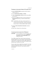
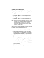
Changing an Instrument’s Network ID Number
To exchange data with an instrument, IDM has to identify the
instrument and establish a communications link with it. IDM
identifies each instrument using a Network ID Number.
The default ID number for all instruments shipped from the
factory is 1. ID Numbers can range from 1 to 254. Each
instrument on the network must have a unique ID Number. IDM
will not recognize more than one instrument with the same ID
Number. If you only intend to use IDM with one instrument,
proceed to the next section, Connecting the Instrument to the PC/
Network, since this information does not apply to your
application.
The easiest way to change an instrument’s ID Number is to use
the COMM menu option in the instrument’s User Program. Refer
to the instrument’s manual for more information.
IMPORTANT:
If multiple instruments are networked together,
they must all have the same COMM settings.
If you are using XMT868s and do not have a Remote Control
Communication Unit (RCCU), you must use IDM to change the
ID Number as follows:
Changing the ID Number for the XMT868
1. Connect one instrument to the network as described in
Connecting the Instrument to the PC/Network on page 2-5.
DO NOT CONNECT MORE THAN ONE instrument.
2. Launch the IDM program.
3. Establish communications with the instrument using the
Connect to a New Instrument command in the “Global”
submenu (ALT+G, ALT+C). Enter ID Number 1.
2-4
Installation
October 2004
Changing an Instrument’s Network ID Number (cont.)
4. Enter the SITE EDIT MENU command in the Edit Function
submenu (page 6-6).
5. Select ONLINE, PROG, GLOBAL and COMM.
6. Click on Next Item/Enter (ALT+N) until the Network I.D?
prompt appears.
7. Enter the new ID Number between 2 and 254 and click on
Exit Page (ALT+X) until you reach the instrument Menu
window.
Note: Use ID Numbers other than 1 for all instruments in a
multiple-instrument installation. This allows you to add
new instruments without having conflicting ID Numbers.
You may want to record the number for future reference.
8. Select the Close Connection to Instrument command
(ALT+M).
9. Repeat steps 1 through 9 for each instrument.
Connecting the Instrument to the PC/Network
IMPORTANT:
If you are planning to network instruments, you
must read the previous section, Changing an
Instrument’s Network ID Number, before
making connections.
To use IDM, you must make a physical connection from the
instrument’s RS232 port to your computer’s serial port (COM1 or
COM2). Most PC serial ports have either a DB9 or DB25 male
connection. You can either order a cable with a mating connector
from the factory or build your own cable.
If you are using a factory-supplied cable, plug the PC end of the
cable into the appropriate serial port. Use Table 2-1 on page 2-6
to make the proper connections to the instrument’s RS232
terminal block.
Installation
2-5
October 2004
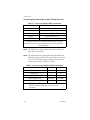
Connecting the Instrument to the PC/Network (cont.)
Table 2-1: Factory-Supplied Cable Connections
Wire Color
Terminal Block Pin
Black
Transmit TX
Red
Receive RX
Green
Common (RTN or GND)
White*
Clear to Send (CTS)
Yellow*
Data Terminal Ready (DTR)
* Not required for IDM. Insulate those leads or cut them
off to prevent shorts. Also, jumper the pins on the terminal
block together.
Note: The PT868 uses a plug-in phone-jack type connector to
make these connections.
Note: See GE Infrastructure Sensing document EIA-RS Serial
Communications (916-054) for more details. If you chose
to use a non-GE Infrastructure Sensing cable, make the
connections as shown in Table 2-2 below.
Table 2-2: Non-Factory Supplied Cable Connections
Terminal Block Pin on Meter
9 Pin
25 Pin
Transmit TX
2
3
Receive RX
3
2
RTN or Com
5
7
Clear to Send (CTS)
not used
not used
Data Terminal Ready (DTR)
not used
not used
Note: The CTS and DTR pins on the meter’s terminal block
should be jumpered together to ensure proper
operation.
2-6
Installation
October 2004
Chapter 3
Initial Setup
Before proceeding with this chapter, make sure that the IDM
software has been installed in accordance with the instructions
provided in Chapter 2, Installation. Also, be certain that the
personal computer has been restarted since the completion of the
installation procedure. Then, follow the instructions below to
perform the initial IDM configuration.
IDM Start-up
IMPORTANT:
When running IDM under Windows 95/98/NT,
disable the screen saver and make IDM the
active window before recording real-time data.
If the screen saver becomes active, or you switch
to another application, IDM’s clock will run slow
after you switch back to IDM. This will cause
IDM to record incorrect time tags for real-time
data.
Running IDM from DOS:
1. At the C:\> prompt, type cd\IDM.
Note: To eliminate changing the directory each time you want to
use IDM, include the C:\IDM directory in the PATH
command in your AUTOEXEC.BAT file.
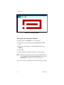
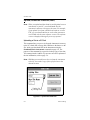
2. Type IDM and hit [ENTER]. Your computer loads the IDM
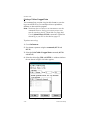
program.
A window similar to that shown in Figure 3-1 on page 3-2
appears.
Initial Setup
3-1
October 2004
Figure 3-1: IDM Main Screen
Running IDM from Windows 95/98/NT
1. Double click on the IDM icon on your desktop.
2. If you did not create a shortcut, select Run from the Start
menu.
3. Using the browse button, go to the IDM folder and select
IDM.exe.
4. Select OK.
A window similar to that shown in Figure 3-1 above appears.
Note: IDM will automatically open an instrument Menu Window
if the Automatic Connection to Instruments option in the
Preferences command is activated (see page 4-7).
You are now ready to use IDM. Proceed to the following section.
3-2
Initial Setup
October 2004
Setting Up IDM
To begin using IDM, we recommend you read or skim the rest of
this chapter to familiarize yourself with how IDM works and the
basic operational features it offers. If you do not want to read the
entire chapter, you should at least read About IDM on page 3-4.
We then recommend you do the following:
•
Select the necessary settings in the Preferences command
as discussed on page 4-7. You should at least select the
serial port, baud rate and printer type options.
IMPORTANT:
If you want to communicate with multiple
instruments, all the instruments must have the
same baud rate, data bits, stop bits, and parity
settings. Refer to the instrument’s manual for
instructions on setting up the communications
port.
•
If you are communicating with multiple instruments, you
must assign each instrument a Network ID number. At the
factory each instrument is shipped with the Network ID
number set to 1. Since IDM will recognize an instrument
only by its unique Network ID number, you cannot have
multiple instruments with the same ID number. Refer to
Changing an Instrument’s Network ID Number on
page 2-4 to change the ID numbers as required.
•
Before IDM can exchange data with an instrument, you
must establish communications with the instrument. You
can use the Connect to a New Instrument command
(refer to page 4-3) to connect to one instrument at a time or,
if you want to connect to multiple instruments, use the
Scan Network for Instruments command (see page 4-6).
After you complete the above, refer to Main Menu on page 4-1 to
begin using IDM.
Initial Setup
3-3
October 2004
About IDM
IDM consists of two sets of top-level menus: the Main Menu and
the Instrument Menu. Each of these menus is made up of
submenus; and the submenus are made up of command options.
The Main Menu consists of submenus and commands that you
can use without actually having to connect to an instrument. The
Instrument Menu, on the other hand, only appears after you
connect to an instrument. Its submenus and commands enable
you to exchange data with an instrument.
IDM always has only one Main Menu. However, each time you
establish communications with an instrument, IDM will open an
Instrument Menu window for that instrument (in addition to the
Main Menu window). For example, if you connect to four
instruments, IDM will open four Instrument Menu windows.
Although IDM can establish communications with multiple
instruments, it can only “talk” to one instrument at a time.
Therefore, to talk to the desired instrument, you must select the
corresponding Instrument Menu window by clicking on it with
the mouse.
3-4
Initial Setup
October 2004
Charts
The Data submenu has two commands to view data in a line or
bar chart. Both types of charts provide various viewing options.
You can also customize charts to fit your own preferences.
This section describes the parts of a chart, shows you how to view
data and customize a chart.
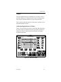
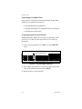
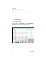
Understanding the Parts of a Chart
Figure 3-2 below shows the parts of a line chart. Bar charts have
the same features in common. You can access these features by
using your mouse to click on the desired button or using the
keyboard equivalents.
untitled
Log Message
Scale
Scales
Time
Symbols
Option Buttons
Figure 3-2: Parts of a Chart
Initial Setup
3-5
October 2004
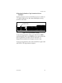
Understanding the Parts of a Chart (cont.)
•
•
The window title bar displays the log message.
The upper-most portion of the chart window displays the
log parameters with their corresponding scales and plotted
values.
•
IDM displays the time on the x-axis, beginning at the
designated log start time. Each point is plotted at the
selected log interval (i.e. every 5 seconds, 10 seconds, etc.).
•
The bottom of the chart window displays the log
parameters with their corresponding symbols. If you are
viewing the chart on a color monitor, the symbols are also
color coded. Since the chart displays up to three log
parameters at once, each parameter is assigned a color and
a symbol for easier viewing on color and monochrome
monitors.
•
The chart provides option buttons that enable you to adjust
the chart scales and view the chart.
Proceed to the following sections to learn how to customize your
chart with the option buttons.
3-6
Initial Setup
October 2004
Using the Chart Viewing Options
When you first view a log in chart form, the chart displays the
first 19 data points. To view additional data points you can use the
following options:
•
•
•
•
Scroll Back - (ALT+B) to move back one data point.
Scroll Fwd - (ALT+F) to move forward one data point.
Prev Page - (ALT+P) to move back one chart screen.
Next Page - (ALT+N) to move forward one chart screen.
Note: When you first display the chart, the chart screen consists
of 19 data points. The number of data points changes as
you zoom in or out; therefore, one chart screen will
consist of the number of data points consistent with the
zoom view you have chosen.
IDM also provides two more options that can increase or decrease
the number of data points displayed on the screen.
•
Zoom Out - (ALT+O) doubles the number of data points
shown on the chart each time you click on this button.
•
Zoom In - (ALT+I) displays half as many data points as
previously shown on the chart. Each time you access this
option, the chart halves the number of data points shown.
Lastly, IDM provides two more options that enable you to view
the log information and exit this command.
•
Statistics - (ALT+S) displays the log message, the total
number of data points for the log, the log start date and
time, and the log end date and time. Statistics also displays
the minimum, maximum, and mean (average) of all values
except for forward and reverse totals. Instead of displaying
the mean for totals, the difference between the first and last
reading is displayed.
•
Exit - (ALT+X) exits the chart option and returns to Data
Menu.
Initial Setup
3-7
October 2004
Customizing a Line/Bar Chart
Once you have selected the desired log and chart format, IDM
enables you to customize the chart by:
•
•
•
changing displayed log parameters
changing the number of log parameters that are displayed
adjusting the vertical scales
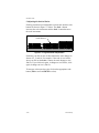
A.Changing Displayed Log Parameters
IDM automatically displays the first three log parameters when
you first view a chart. Use the steps below to view other log
parameters:
1. Click on the log parameter box (TAB to scroll and ENTER to
select).
Log Parameter Box
Log Parameter Box
Figure 3-3: Log Parameter Selection
2. The available log parameters are listed in a drop-down menu.
Click on the desired parameter and hit ENTER.
3. Repeat the above steps as desired.
3-8
Initial Setup
October 2004
B.Changing the Number of Log Parameters that are
Displayed
Each log parameter box has an ON/OFF box next to it. When an
“X” appears inside the box, this means IDM displays the log
parameter on the chart.
ON/OFF Box
Figure 3-4: Log Parameter Display
To shut off a log parameter, click on the ON/OFF box (TAB to
scroll through the choices, and ENTER to select) that corresponds
to the log parameter you want to shut off. When the “X”
disappears, the parameter also disappears from the chart.
To turn on a log parameter, click on the ON/OFF box again (TAB
and ENTER). The log parameter reappears.
Initial Setup
3-9
October 2004
C.Adjusting the Vertical Scales
Each log parameter has an adjustable vertical scale and two scale
buttons as shown in Figure 3-5 below. The Scale + button
increases the scale increments and the Scale - button decreases
the scale increments.
Scale Buttons
Figure 3-5: Log Parameter Adjustment
Each time you click on one of these buttons the scale changes in
factors of 2, 5, and 10. For example, if the scale is 0 to 100 ft/s,
when you click on the Scale + button, the scale changes to 0 to
200 ft/s. If you click on it again, it changes to 0 to 500 ft/s; click
again, it changes to 0 to 1,000 ft/s.
To increase or decrease the scale, click on the appropriate scale
button (TAB to scroll and ENTER to select).
3-10
Initial Setup
October 2004
How to Print Screens/Charts
IDM provides a command that enables you to print IDM
windows (including charts) appearing on your PC screen. To print
IDM screens, you must have a Hewlett Packard PCL-compatible
laser or PostScript® printer. IDM will not print to other printers.
Use the steps below to properly setup IDM to print data.
1. Select the Preferences command (ALT+G and ALT+P).
2. Click on the Graphics Printer Type box (TAB to scroll and
ENTER to select).
Figure 3-6: Graphics Printer Selection
3. Select the appropriate printer type (↓ and ENTER).
4. Click on OK (ALT+O).
5. Display the desired data on your screen.
Note: IDM will only print the active window.
6. Using the computer’s keyboard, press and hold down the Shift
key while you press the Print Scrn key. Depending on your
particular computer, the command for printing a screen
display may be:
•
Print Scrn
•
Cntrl + Prnt Scrn
•
FN + Prnt Scrn
Initial Setup
3-11
October 2004
How to Print Screens/Charts (cont.)
To print a graph, you must display the graph on the screen and use
your computer’s Print Scrn command. This is done by pressing
and holding down the Shift key while you press the Print Scrn
key.
IDM sends the data to your printer.
3-12
Initial Setup
October 2004
Chapter 4
Instrument Setup
After your hardware and software has been installed as described
in Chapters 2 (Installation) and 3 (Initial Setup) of this manual
and the instrument’s User’s Manual, the procedure for
establishing communications with an instrument may be started.
Main Menu
As discussed in About IDM on page 3-4, IDM has two sets of
menus: the Main Menu and the Instrument Menu. The Main
Menu window appears when you enter IDM and consists of
following two submenus:
• Global - contains commands to enter setup data and initiate
communications between the PC, dial-up modem, and
instrument(s)
•
Data - displays logs in a chart and can also save or print
logs in ASCII format so they can be downloaded into a
database, spreadsheet or word-processing program
IMPORTANT:
When operating IDM, do not press any of the
keys on the instrument keypad or communicate
with a Remote Control Communications Unit
(RCCU). You should use your mouse or the PC’s
keyboard to control communication. Also make
sure the instrument is in normal RUN mode.
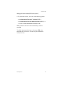
The commands associated with the above submenus are
described in the following sections.
Instrument Setup
4-1
October 2004
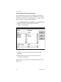
Global Submenu
Figure 4-1: Global Submenu Selection
The Global submenu consists of the following commands:
4-2
•
Connect to a New Instrument - establishes
communications with a new instrument.
•
Select an Existing Instrument - lets you switch from
“talking” with one instrument to another when IDM is
connected to multiple instruments.
•
Scan Network for Instrument - automatically establishes
communications with all the instruments connected to the
network.
•
Preferences - enables you to select the communications
port, baud rate, printer type and column separators for logs
(when saving logs as ASCII files). You can also set IDM to
automatically connect to instruments upon entering the
program.
•
•
Dial Modem - tells a modem to connect to an instrument.
•
Exit - exits the IDM program.
Hang up Modem - disconnects your computer from the
instrument.
Instrument Setup
October 2004
Connecting to a New Instrument
Before IDM can exchange data with an instrument, it must
establish a communications link. The Connect to a New
Instrument command enables you to establish a link with an
instrument. This command is particularly helpful if you have a
multiple-instrument installation and you want to connect to one
specific instrument.
Note: If you are using multiple instruments, each meter must
have a unique ID Number. See Changing an Instrument’s
Network ID Number on page 2-4 for more information.
Note: IDM also provides two other commands that enable you to
establish communications. The Scan Network for
Instruments command (page 4-6) searches the network
for instruments and establishes communications with each
instrument. The Preferences command (page 4-7) has an
Auto-Connect option that directs IDM to search and
establish communication with each instrument upon
entering the program.
To establish communication with an instrument:
1. If you have not done so, select the serial port and baud rate
using the Preferences command as described in Using
Preferences on page 4-7.
IMPORTANT:
All instruments on a network must have the same
baud rate (typically 9600), data bits, stop bits,
and parity settings. Refer to the instrument’s
manual for instructions on setting up the
communications port.
2. Select the Connect to a New Instrument command (ALT+G
and ALT+C).
3. Enter the instrument’s ID number (1 to 254).
4. Select OK (ALT+O).
Instrument Setup
4-3
October 2004
Connecting to a New Instrument (cont.)
IDM retrieves system, channel, log and code information from
the instrument and opens a new Instrument Menu window. You
should repeat steps 2 and 3 for any other meters that you want to
use.
Although IDM can establish simultaneous communications with
multiple instruments, it can only talk to one instrument at a time.
Therefore, to talk to the desired instrument, you must select the
corresponding Instrument Menu window by clicking the mouse
on it (you can also use the Select an Existing Instrument
command to switch windows).
Note: Every time you connect to an instrument, a new window
with an Instrument Menu appears. Each Instrument Menu
window takes up a significant amount space on the
screen; therefore, if you are planning to connect to
multiple instruments, you should minimize the Instrument
Menu windows you are not using.
4-4
Instrument Setup
October 2004
Selecting an Existing Instrument
Although IDM provides the capability of connecting to multiple
instruments, you can only talk to one instrument at a time. The
Select an Existing Instrument command lets you switch from
one instrument to another.
To select an instrument:
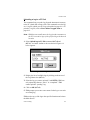
1. Choose the Select an Existing Instrument command
(ALT+G and ALT+S). A window similar to the one shown in
Figure 4-2 below appears.
Figure 4-2: Instrument Selection
2. Display the available instruments by clicking on the
downward arrow of the Select System Window box (ENTER).
A list of instruments appears.
Note: The list will only display instruments that have a
communications link with IDM.
3. Select the desired instrument (↓ and ENTER).
Note: You can use this command to select an instrument even if
the Instrument Menu window is minimized.
4. Select OK (ALT+O).
The Instrument Menu window for the specified instrument
appears.
Instrument Setup
4-5
October 2004
Network Scan for Instruments
When issued, this command scans the network for instruments
and establishes communications with each one. You can specify
how many instruments you want IDM to search for and a range of
ID numbers to scan within. This command can take as long as 10
minutes to complete if you are scanning for a substantial number
of instruments.
Note: If you are using multiple instruments, each instrument
must have a unique ID Number. See Changing an
Instrument’s Network ID Number on page 2-4 for more
information.
To scan the network for instruments:
1. Select the Scan Network for Instruments command (ALT+G
and ALT+N).
2. Enter the number of instruments that you want to search for
and the maximum network ID number to scan. For example, if
you want to search for five instruments and all of their ID
numbers are under 20, enter 5 in the first box and 20 in the
second box.
IMPORTANT:
All instruments on a network must have the same
baud rate, data bits, stop bits, and parity
settings. Refer to the instrument’s manual for
instructions on setting up the communications
port.
3. Select Start Scan (ALT+S) to begin. Press Cancel (ALT+C) at
any time to stop scanning.
IDM opens a new Instrument Menu window for each instrument.
4-6
Instrument Setup
October 2004
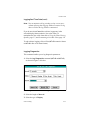
Using Preferences
The Preferences command enables you to enter set up
information for the overall operation of IDM. This command lets
you select the following:
•
•
•
•
serial port
•
which instruments IDM will automatically establish
communications with when entering the program (AutoConnect Option).
baud rate
printer type
column separator for logs (used when saving a log as an
ASCII file)
Note: The Preferences command also has options for setting up
a modem. Refer to Using Dial Modem on page 4-8.
To select or change any of these settings:
1. Select the Preferences command (ALT+G and ALT+P).
2. Click on the desired boxes (TAB and ENTER) and make your
selections.
IMPORTANT:
All instruments on a network must have the same
baud rate, data bits, stop bits, and parity
settings. Refer to the instrument’s manual for
instructions on setting up the communications
port.
3. Select OK (ALT+O).
IMPORTANT:
Instrument Setup
If you are using a mouse and you select the port
that your mouse is connected to, IDM will
disable your mouse. If this happens, reenter the
Preferences command and reset the serial port. If
IDM does not allow you to reset the serial port,
either restart IDM or reboot your computer.
4-7
October 2004
Using Dial Modem
The Dial Modem command enables you to use your computer’s
modem to communicate with an instrument at a remote location
rather than using the RS232 or RS485 port. To use this feature,
you must first set up the following parameters using the
Preferences command.
1. Select the Preferences command (ALT+G and ALT+P).
2. Select the serial port.
3. At the serial port select “Hayes-Type Modem.”
4. Enter the remote modem’s telephone number in the Dial
Number box. This string can include the Hayes modem “Dial
string” command characters (“P” for pulse-dial, “,” for pause,
etc.), but do not enter the Hayes dial command’s initial “ATD”
prefix, as IDM already provides this.
5. If you want IDM to dial the remote modem every time it runs,
select the “Dial Modem at Startup” checkbox.
Note: You can automate the process of dialing the remote
modem and connecting to the remote instrument by
selecting both the “Dial Modem at Startup” and “Autoconnect at Startup” checkboxes. Then, when IDM runs, it
automatically dials the remote modem and connects to the
instruments specified in the Preferences window’s “autoconnect list.”
6. Select OK.
7. To dial the modem, select the Dial Modem command (ALT+G,
↓, and ENTER).
8. Use the Connect to New Instrument command to connect to
the remote instrument.
4-8
Instrument Setup
October 2004
Using Hang Up Modem
This command hangs up the modem, disconnecting IDM from
the remote modem. The Hang Up Modem command (ALT+G, ↓,
and ENTER) does not close the open display windows; you should
do this yourself before hanging up the modem. IDM
automatically hangs up the modem when exiting the program.
Exiting
To exit IDM:
1. Select the Exit command (ALT+G and ALT+X).
2. Use the mouse or keyboard to:
•
•
select Yes (ALT+Y) and exit IDM.
select No (ALT+N) and return to IDM.
Note: In addition to the Exit command you can exit IDM at
anytime by pressing CTRL+C.
Instrument Setup
4-9
October 2004
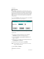
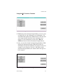
Data Submenu
Figure 4-3: Data Submenu Selection
The Data submenu, as shown in Figure 4-3 above, consists of the
following commands
•
View Line Chart of Log Data - displays the specified log
in a point-to-point line chart.
•
View Bar Chart of Log Data - displays the specified log in
a bar chart.
•
Print Table of Log Data - prints the specified log in table
format or saves the log in ASCII format.
Each of the commands in the Data submenu will only display
logs that are stored on your PC’s hard disk or on a floppy disk. If
the log or logs you want to view are stored in the instrument’s
memory, you must upload them to your PC’s hard disk or floppy
disk using the Upload Site to PC Disk command (refer to
page 6-1).
4-10
Instrument Setup
October 2004
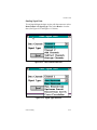
Viewing a Line Chart or Bar Chart of Log Data
The first two commands in the Data submenu display logged data
in a line or bar chart. Once you chart the desired log, you can use
the many options available to view data or customize the chart to
meet your needs.
Use the following steps to chart the desired logs:
Note: You do not have to connect to an instrument to use these
commands. However, the log you want to view must be
stored on your PC’s hard disk or a floppy disk. If it is not,
use the Upload Site to PC Disk command (page 6-1) to
upload the desired log to your PC.
1. Select the View Line Chart of Log Data command (ALT+D
and ALT+L) or View Bar Chart of Log Data (ALT+D and
ALT+B) depending on the type of chart you want.
2. Select the desired log (TAB to scroll and ENTER to select).
To manipulate the chart, refer to Using the Chart Viewing Options
on page 3-7 and Customizing a Line/Bar Chart on
page 3-8. To print the chart, refer to How to Print Screens/Charts
on page 3-11.
Instrument Setup
4-11
October 2004
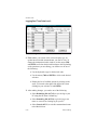
Printing a Table of Logged Data
This command lets you print a log (in table format) or save the
log as an ASCII file so you can import it into a spreadsheet,
database or other software program.
Note: You do not have to connect to an instrument to use this
command. However, the log you want to print or save
must be stored on your PC’s hard disk or a floppy disk.
Use the Upload Site to PC Disk command to upload the
desired log to your PC as described on page 6-2.
To print or save a log:
1. Go to Preferences.
2. Set column separators using the command (ALT+G and
ALT+P).
3. Select the Print Table of Logged Data command (ALT+D
and ALT+P).
4. Select the desired log (TAB and ENTER). A window similar to
the one shown in Figure 4-4 below appears.
Figure 4-4: Log Record Selection
4-12
Instrument Setup
October 2004
Printing a Table of Logged Data (cont.)
This dialog box displays the name of the log you selected and the
number of records contained in that log. A record contains the
readings for each log parameter for one log interval. For example,
if you log readings every 5 seconds for 12 hours, your log will
contain 8,640 records (readings).
5. Select the number of records desired (TAB and ENTER). Use
the Range option to enter the range of records you want to
view.
6. Do one of the following:
•
Select To Printer (ALT+P) to send the log to a printer and
exit this command.
•
Select To File (ALT+F) to save the log as an ASCII file and
proceed to Step 7.
IMPORTANT:
When you print to a file, IDM saves the data as a
.prt file. This is the only way you can change a
log to a text file so that you can view it in a
spreadsheet program such as Excel, Lotus 123,
or Quattro Pro.
7. IDM now prompts you to give the ASCII file a name. Save the
file using a new name or overwrite an existing output file.
8. Select OK (ALT + O).
IDM writes the log to an ASCII file and exits this command.
Instrument Setup
4-13
October 2004
Chapter 5
IDM Operation
Each time you connect to an instrument, IDM opens a new
window displaying the Instrument Menu. If you are
communicating with multiple instruments, you can minimize the
windows you are not using to save space on your PC screen.
Instrument Menu
The Instrument Menu consists of the following commands:
•
System - enables you to adjust the PC and instrument
clocks, print and delete site data, clear totalizers, erase logs
from the instrument’s memory and disconnect
communications with an instrument.
•
Upload/Download - uploads and downloads site data
between the PC and the instrument and downloads logs
from the instrument to the PC.
•
Edit Functions - edits site data and logs, and also enables
you to calibrate your unit.
•
Real-Time - displays and logs real-time data.
The commands associated with the above submenus are
described in the following sections.
IMPORTANT:
IDM Operation
When operating IDM, do not press any of the
keys on the instrument keypad or communicate
with a Remote Control Communications Unit
(RCCU). You should use your mouse or the PC’s
keyboard to control communication. Also make
sure the instrument is in normal RUN mode.
5-1
October 2004
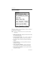
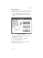
System Submenu
Figure 5-1: System SubMenu Selection
The System submenu, as shown in Figure 5-1 above, consists of
the following six commands:
Note: All of these commands may not be accessible with all
instruments.
5-2
•
Read Instrument Clock - displays the date and time of the
PC and instrument clocks.
•
Set Instrument/PC Clocks - lets you edit or synchro-nize
the instrument date and time to your PC date and time.
•
Print Site - prints a site that is stored in the instrument’s
memory.
•
Delete Stored Site - erases the specified site from the
instrument’s memory.
•
Clear Instrument Totalizers - resets the forward and
reverse totals to zero. This is used only for flowmeters.
•
Erase Log from Instrument - erases a log file from the
instrument’s memory.
IDM Operation
October 2004
System Submenu (cont.)
•
Close Connection to Instrument - terminates
communication with an instrument and closes the
Instrument Menu window. (Closing the Instrument Menu
window with the control-menu box also terminates
communication with the instrument.)
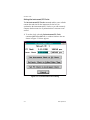
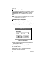
Reading the Instrument Clock
The Read Instrument Clock command displays the current date
and time of both the instrument and your PC.
If you want to change the date and time of your instrument or PC,
use the Set Instrument/PC Clocks command as described on
page 5-4.
To view the date and time:
1. Select the Read Instrument Clock command (ALT+S and
ALT+R). A window similar to that shown in Figure 5-2 below
appears:
Figure 5-2: Instrument/PC Clock Reading
2. To exit, select Cancel (ALT+C).
IDM Operation
5-3
October 2004
Setting the Instrument/PC Clocks
The Set Instrument/PC Clocks command enables you to edit the
current date and time for the instrument. It also lets you
synchronize the instrument and PC clocks so you can accurately
compare data between sites. Synchronization is accurate to one
second.
1. To set the clock, select the Set Instrument/PC Clock
command (ALT+S and ALT+S). A window similar to the one
shown in Figure 5-3 below appears.
Figure 5-3: PC/Instrument Clock Setting
5-4
IDM Operation
October 2004
Setting the Instrument/PC Clocks (cont.)
2. To synchronize clocks, select one of the following options:
•
•
•
Set Instrument Clock to PC Clock (ALT+P), or
Set Instrument Clock to Edited Date/Time (ALT+E), or
Set PC Clock to Instrument Clock (ALT+M).
IDM synchronizes the clocks and automatically exits this
command.
To edit the instrument clock, move the cursor (TAB) to the
instrument date or time box. You can only edit information
enclosed in a box.
IDM Operation
5-5
October 2004
Printing the Site
The Print Site command prints a specified site. But you must
have the meter connected to your computer. This command will
only let you print sites that are stored in the instrument’s memory.
IDM will ask you to print to a file or a printer. If you select To
File, it saves it as a *.prt text file, which you can import into a
word processor.
If you select To Printer, the file will be directed to your attached
printer, but it is not saved to your hard drive.
Figure 5-4: Print Site Setting
To print a site:
1. If you have not selected a printer type, do so using the
Preferences command as described on page 4-7.
2. Select the Print Site command (ALT+S and ALT+P). (See
Figure 5-4 above.)
3. Display the list of available sites by clicking on the arrow of
the Existing Sites box (ALT+X).
4. Select the site you want to print (↓ and ENTER).
Note: The Working Site is the site the instrument is currently
using to take measurements.
5. Select To File or To Printer.
IDM prints the selected site.
5-6
IDM Operation
October 2004
Deleting a Stored Site
This command enables you to delete unwanted site files from the
instrument’s memory. Use the steps below to delete a site file.
1. Select the Delete Stored Site command (ALT+S and ALT+D).
A window similar to the one shown in Figure 5-5 below
appears.
Display list
by clicking here
Figure 5-5: Site Selection
2. Display the list of available sites by clicking on the arrow of
the Existing Sites box (ALT+X).
3. Select the site you want to delete (↓ and ENTER).
4. Click on Selected Site (ALT+S).
IDM deletes the site file from the instrument’s memory and
automatically exits to the Main Screen.
IDM Operation
5-7
October 2004
Clearing the Instrument Totalizers
To clear the instrument’s forward and reverse totalizers, select the
Clear Instrument Totalizers command (ALT+S and ALT+C).
IDM automatically clears the totalizers and exits to the Main
Screen.
Note: Totalizers are used only for flowmeters. This menu item is
grayed out for other instruments.
Erasing a Log from an Instrument
This command enables you to delete unwanted logs from the
instrument’s memory. Use the steps below to delete a log.
1. Select the Erase Log from Instrument command (ALT+S and
ALT+E). A window similar to the one shown in Figure 5-6
below appears.
Figure 5-6: Log Selection
2. Display the list of available logs by clicking on the arrow of
the Log Names box (ALT+L).
3. Select the log you want to delete (↓ and ENTER).
4. Click on OK (ALT+O).
IDM deletes the log from the instrument’s memory and
automatically exits to the Main Screen.
5-8
IDM Operation
October 2004
Closing the Connection to an Instrument
This command terminates communication with the specified
instrument and closes the Instrument Menu window associated
with it.
To disconnect an instrument, select the Close Connection to
Instrument command (ALT+S and ALT+M). IDM automatically
disconnects the current instrument.
IDM Operation
5-9
October 2004
Chapter 6
Data Handling
After IDM has been installed and configured in accordance with
the instructions given in the first five chapters of this manual, you
are ready to begin collecting data.
Upload/Download Submenu
Figure 6-1: Upload/Download Selection
The Upload/Download submenu, as shown in Figure 6-1 above,
consists of three commands that let you exchange site and log
files between your PC and instrument. The Upload/Download
submenu consists of the following commands:
•
Upload Site to PC Disk - sends a copy of site data from the
instrument’s memory to the PC’s hard disk or to a floppy
disk.
•
Download Site to Instrument - sends a copy of site data
from the PC’s hard disk or floppy disk to the instrument’s
memory.
•
Upload Log to PC Disk - sends a copy of a log from the
instrument’s memory to the PC’s hard disk or to a floppy
disk.
Data Handling
6-1
October 2004
Upload/Download Submenu (cont.)
Note: When you upload and download site and log data between
instruments or your PC, you should make sure the
instrument’s software versions are the same. For example,
if you upload a site from a DF868 with software version
F2K, you can download that site to the same instrument
or a DF868 with the same software version. The software
version is displayed during the power up sequence.
Uploading a Site to a PC Disk
This command lets you save a site from the instrument’s memory
to the PC’s hard disk or floppy disk. IDM saves the data as a .sit
file, which can download back to the instrument using the
Download Site to Instrument command on page 6-4. The
purpose of the command is to provide a backup copy of site data.
You cannot print the *.sit file. If you want a text file or printout of
the site information, refer to page 5-6.
Note: IDM does not actually move the site from the instrument
to the PC, but sends a copy of the specified site to the
desired location.
Display list
by clicking here
Figure 6-2: Upload Site Selection
6-2
Data Handling
October 2004
Uploading a Site to a PC Disk (cont.)
1. Select Upload Site to PC Disk command (ALT+U and
ALT+U). A window similar to the one shown in Figure 6-2 on
page 6-2 appears.
2. Display the list of available sites by clicking on the arrow of
the Existing Sites box (ALT+X).
3. Select the site you want to upload (↓ and ENTER).
Note: The Working Site is the site the instrument is currently
using to take measurements.
4. Choose Selected Site (ALT+S).
5. IDM prompts you to enter a new file name for the site or
overwrite an existing site file.
IDM sends a copy of the site to the specified location and exits to
the main screen.
Data Handling
6-3
October 2004
Downloading a Site to an Instrument
This command lets you send a site from the PC’s hard disk or
floppy disk to the instrument’s memory. IDM does not actually
move the site from the PC to the instrument, but sends a copy of
the specified site to the instrument’s memory.
1. Select Download Site to Instrument command (ALT+U and
ALT+D). A window similar to the one shown in
Figure 6-3 below appears.
Figure 6-3: Download Site Selection
2. Select the site you want to download and click on OK
(ALT+O).
3. IDM prompts you to enter a new name for the site or
overwrite an existing site.
IDM sends a copy of the site to the instrument and exits to the
Main Screen.
6-4
Data Handling
October 2004
Uploading a Log to a PC Disk
This command lets you send a log from the instrument’s memory
to the PC’s hard disk or floppy disk. This command saves the log
as a *.log file, which you can view as described on page 4-10. To
print the *.log file, refer to Print Table of Logged Data on
page 4-12.
Note: IDM does not actually move the log from the instrument to
the PC, but sends a copy of the specified log to the desired
location.
1. Select Upload Log to PC Disk command (ALT+U and
ALT+U). A window similar to the one shown in Figure 6-4
below appears.
Figure 6-4: Log Selection
2. Display the list of available logs by clicking on the arrow of
the Log Names box (ALT+L).
3. Select the log you want to upload (↓ and ENTER). IDM can
only upload logs that are “active” or “completed.” IDM
cannot upload a “pending” log.
4. Click on OK (ALT+O).
5. IDM prompts you to enter a new name for the log or overwrite
an existing log.
IDM sends a copy of the log to the specified location and exits to
the Main Screen.
Data Handling
6-5
October 2004
Using the Edit Functions Submenu
This command enables you to edit site and log information,
calibrate and test option cards, and perform other functions. The
commands listed under the Edit Functions submenu depend on
the instrument and its available options.
The site, log and calibration/test information will be different
depending on the particular instrument you use. Refer to the
menu maps in your instrument’s manual to help guide you.
The three most common commands in the Edit Functions
submenu are:
•
SITE EDIT MENU - enables you to enter and change site
information.
•
LOG EDIT MENU - lets you enter and change log
information.
•
Calibration/test - lets you calibrate outputs and test
installed option cards.
Use the general information that follows to use the above
commands.
1. Select the desired command (ALT+E, ↓ and ENTER). A
window similar to the one shown in Figure 6-5 on page 6-7
appears. (This screen represents the Site Edit Menu command
for a Two-Channel GM868).
6-6
Data Handling
October 2004
Using the Edit Functions Submenu
Figure 6-5: Site Edit Selection
2. IDM displays the instrument Program Menus you use to enter
or change the site, log, calibration, or test information. The
information that appears in the IDM windows will be the same
as the menu structure described in the instrument’s user
manual. To enter information, use the mouse (TAB and
ENTER) and enter the desired instrument Program Menus.
3. Once you enter the desired instrument Program Menus, IDM
displays the instrument Prompts. IDM will read the site
information stored in the instrument one prompt at a time. For
example, if you clicked on Channel 1 and System in the
instrument Program Menus, the window shown in Figure 6-6
below appears.
Figure 6-6: Channel 1/System Selections
Data Handling
6-7
October 2004
Using the Edit Functions Submenu (cont.)
Prompt
Window
Options
Figure 6-7: Site Edit Window Options
IDM reads only the first prompt (see Figure 6-7 above): Channel
Label. You can do one of the following.
Use one of the window options:
•
Return to the previous prompt/menu by selecting
Previous Item (ALT+P)
•
View the next prompt by selecting Next Item/Enter
(ALT+N).
•
Exit the current menu or sub-menu by selecting Exit
Page (ALT+X).
Enter site information:
•
Use the keyboard to type in the desired information.
•
Use the mouse (TAB and ENTER) to click on the desired
selection.
•
Display the list of available options by clicking on the
arrow (↓) located at the right of the desired box, then
clicking on your selection (↓ and ENTER).
Refer to your instrument’s user manual as a guide to moving
through the instrument Program Menus.
6-8
Data Handling
October 2004
Using the Real Time Sub-Menu
Figure 6-8: Real Time Selections
This submenu, which is shown in Figure 6-8 above, enables you
to log real-time measurements and diagnostics, and view signal
data.
Logging Real Time Data
This command enables you to simultaneously view and log up to
ten parameters using your PC. A single log file can hold data
from different instruments. You can choose to display the realtime log in numeric form or in a line or bar chart. IDM stores
measurements on your PC to the specified file. Use the steps
below to view and log real time measurements.
Note: When you log data, the log start date and time must
exceed the current date and time of both the instrument
and PC clocks; therefore, you should synchronize the
instrument and PC clocks before logging data.
This command saves the log as a *.log file, which you can view
as described on page 4-10. To print the *.log file, refer to Print
Table of Logged Data on page 4-12.
1. Select the Log Real Time Data command (ALT+R and
ALT+L). A window similar to the shown in Figure 6-9 on
page 6-10 appears.
Data Handling
6-9
October 2004
Logging Real Time Data (cont.)
Figure 6-9: Real Time Data Selection
2. IDM enables you to enter a title, select a display type, an
update interval and the measurements you want to view. To
change the information in this window, use the mouse (TAB
and ENTER) to click on the desired location to edit. Depending
on the parameter you are editing, you will have to do one of
the following:
•
Use the keyboard to type in the desired value.
•
Use the mouse (TAB and ENTER) to click on the desired
selection.
•
Display the list of available options by clicking on the
arrow (↓) located at the right of the desired box, then
clicking on your selection (↓ and ENTER).
3. After making changes, you can do one of the following:
6-10
•
Select Default log file (ALT+D) to save the log to your
PC using the file name “default.log.”
•
Select Named log file (ALT+N) to give the log a new
name or overwrite an existing log on your PC.
•
Select Cancel (ALT+C) to exit this command and return
to the Main Screen.
Data Handling
October 2004
Logging Real Time Data (cont.)
Note: You can minimize the log window to clear screen space
without affecting data logging. IDM will continue to log
data even when the log window is minimized.
If you do not select Cancel, the real time log appears in the
selected display format (numeric, line or bar chart). To
manipulate the line or bar chart refer to Using the Chart Viewing
Options, page 3-7, and Customizing a Line/Bar Chart, page 3-8.
To end real-time logging, click on Exit (ALT+E in numeric format
or ALT+X in line or bar chart format).
Logging Diagnostics
This command enables you to log diagnostic parameters.
1. Select the Log Diagnostics command (ALT+R and ALT+D),
as shown in Figure 6-10 below.
Figure 6-10: Real Time Diagnostics Selection
2. Select the length of Interval.
3. Select the type of Display.
Data Handling
6-11
October 2004
Logging Diagnostics (cont.)
4. Use the pull down menu to sselect the channel format.
•
Channel 1
•
Channel 2
•
Add Channels
•
Subtract Channels
•
Average Channels
To view the data, select Named File, or click on the Default File,
which displays the screen shown in Figure 6-11 below.
Figure 6-11: Diagnostic Chart Selection
You can select up to three traces to view in the graph window.
The parameters in the pull down menus vary according to the
type of instrument used to gather data.
6-12
Data Handling
October 2004
Reading Signal Data
To read signal diagnostic data, use the pull down menus to select
Data Channel and Signal Type. Then select Read to view the
data. (See Figure 6-12 and Figure 6-13 below.)
Figure 6-12: Data Channel Selection
Figure 6-13: Signal Type Selection
Data Handling
6-13
October 2004
Appendix A
Importing ASCII Files into Microsoft
Excel
Microsoft Excel accepts tabs or commas as column delimiters. To
import an IDM.prt file into Excel:
1. Launch Excel.
2. Select the File Menu.
3. Select Open.
4. Under Files of Type, choose All Files (*.*)
5. Open the *.prt file you wish to import.
Note: You cannot open *.sit or *.log files directly. You must first
convert them to *.prt by printing them to a file. See
page 5-6 for site files and page 4-12 for log files.
6. Set Delimiters to tabs or commas. Excel will not recognize
spaces, semicolons, etc., as delimiters.
7. Press the OK button and then the FINISH button.
Importing ASCII Files into Microsoft Excel
A-1
October 2004
Appendix B
Frequently Asked Questions
Q: How do I upload a log from my instrument and bring it into a
spreadsheet?
A: See Printing a Table of Logged Data, page 4-12.
Q: How do I bring my program (site) data into a word processor?
A: See Printing a Table of Logged Data, page 4-12.
Q: How do I print a graph out of IDM?
A: See How to Print Screens/Charts, page 3-11.
Q: Why can’t I establish communication with my unit?
A: See Connecting the Instrument to the PC/Network,
page 2-5. Also see Connecting to a New Instrument, page 4-3.
Q: How do I program meters using IDM?
A: See Instrument Menu, page 5-1.
Q: How do I view the line data from the instrument?
A: See Using the Chart Viewing Options, page 3-7.
Q: How do I log data to a hard drive?
A: See Uploading a Site to a PC Disk, page 6-2.
Q: How do I log real time data to a hard drive?
A: See Logging Real Time Data, page 6-9.
Frequently Asked Questions
B-1
USA
1100 Technology Park Drive
Billerica, MA 01821-4111
Web: www.gesensing.com
Ireland
Shannon Industrial Estate
Shannon, County Clare
Ireland