1
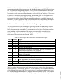
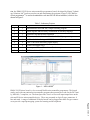
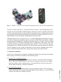
Paper ID #12960 Microcontrollers for Non-Electrical Engineering Students - Do We Need to Teach Assembly Language? Dr. Shouling He, Vaughn College of Aeronautics & Technology Dr. Shouling He is an associate professor of Engineering and Technology at Vaughn College of Aeronautics and Technology, where she is teaching the courses in Mechatronics Engineering and Electrical Engineering Technology. Her research interests include modeling and simulation, microprocessors and PLCs, control system designs and Robotics. She has published more than 45 journal and conference papers in these research areas. Dr. Yuhong Zhang, Texas Southern University Dr. Fangyang Shen, New York City College of Technology (CUNY) Fangyang Shen received his Ph.D. from Auburn University. He had fifteen years’ research and teaching experience in wireless networks, computer education and high performance computing. He had four years’ experience as a computer engineer. He is currently a faculty at New York City College of Technology (CUNY) and published over thirty journal and conference papers. He also served as guest editor and associate editor for Journals, such as Parallel Computing and Computer and Electrical Engineering and chair for multiple international conferences. Dr. Shen is an engineering technology and computer education expert with global view. Page 26.1151.1 c American Society for Engineering Education, 2015 Microcontrollers for Non-Electrical Engineering Students - Do We Need to Teach Assembly Language? Abstract Nowadays, most engineering departments offer microcontroller (or microprocessors) related courses due to the broad applications of computers. For Electrical and Computer Engineering (ECE) or Electrical and Computer Engineering Technology (ECET) department, students normally take two or three courses to learn microcontrollers (or microprocessors), such as assembly language programming, embedded system designs, computer interfacing and computer organization. However, for a non-ECE program, such as Mechanical Engineering, Manufacturing Engineering or Mechatronics Engineering program, students most likely only take one Microcontrollers (or Microprocessors) course. Then, teaching non-ECE students from the architecture of a microcontroller to broad applications in both low-level and high-level programming languages can be very challenging. In this paper, we present a unique approach that has been applied in the Microcontrollers course in the past few years. We have limited the content for the exercises in a low-level language, i.e. assembly language, in (1) understanding how the machine code works, (2) comprehending the flow of control for a high-level language in a real-time system, e.g. the time delay is generated by multiple loops, the assembly language is used to demonstrate how it works, (3) the needs for a microcontroller to use hardware architecture, such as stack and interface operations. The course schedule is in assembly language programming for about 30% of time and 70% of time is in embedded C programming. The course has been taught this way for Mechatronics Engineering students for three years. The result is very positive and encouraging. The future improvement can consist of (1) making a list for the required knowledge for the course, so that students can prepare themselves before they come to the class; (2) developing different levels of problems so that students can practice based on their levels. Page 26.1151.2 1. Introduction Microcontrollers and microprocessors are playing an important role in a wide range of engineering applications. Engineers from many disciplines benefit from microcontrollers and microprocessors in solving engineering problems. In most colleges or schools of engineering, microcontroller courses are taught by the electrical and computer engineering programs and in some cases by mechanical or mechatronics engineering programs. Traditionally, the course focuses on teaching assembly language programming since an assembly language is the mnemonic form of the machine code. An instructor can systematically discuss the organization of a microcontroller (or microprocessor), i.e. ALU, CPU, data flow, registers, and memory, while students take exercises in the assembly language to better understand system architecture of the microcontroller (or microprocessor). Further, in an advanced course, such as embedded systems or computer interfacing, a high-level programming language, such as embedded C, will be taught with applications using microcontrollers. However, for non-electrical and computer engineering students, since their primary courses are in their professional areas such as mechanical, mechatronics or manufacturing engineering, etc, the course credits for them to learn microcontrollers, embedded systems or even high-level programming language are very limited. Under the circumstance, teaching the microcontrollers (or microprocessors) for non-electrical engineering students has several challenges. The first challenge is in the hardship to cover so many types of microprocessors and microcontrollers and various programming languages within a limited amount of time during a semester1. The second challenging factor is in students possibly having different interests and knowledge backgrounds for microcontrollers (or microprocessors) 2: while the majority of students have not been exposed to any microcontrollers (or microprocessors), some students have already possessed advanced programming experience from high school Robotics lessons or pure hobbies. Both types of students might feel that an assembly language is not quite attractive: the former students may not be able to follow the problem solving approach in digital electronics and microprocessors so quickly and the latter students couldn't see the direct help to solve some advanced problems, such as programming smart phone or tablet applications. Especially, from the professional development point of view, when non-ECE engineering students come to a Microcontroller course, they are anticipated to effectively solve problems in their professional areas, rather than a deep understanding of the structure inside a microcontroller (or a microprocessor). Therefore, as educators, we have to ask the problem: is the traditional approach to teach the Microcontrollers (or Microprocessors) course adequate for non-ECE engineering students? From a practical perspective, assembly languages are seldom used to solve problems in the real world since it is very easy to make bugs and quite difficult to find and debug them. Most industrial employers may prefer engineering graduates to master at least one high-level programming language for microcontroller applications. Hence, the further question is: do we need to teach the assembly language of a microcontroller in the microcontroller course for non-electrical engineering students? To answer it, we consider the following questions may assist us in approaching a logical conclusion: Page 26.1151.3 1) How does learning assembly language programming help students understand a microcontroller (or microprocessor)? 2) If we need to choose some parts of an assembly language to teach, what topics should we choose? This paper will be organized in the following way: in the next section, we will analyze the microcontroller related courses taught in the Electrical and Computer Engineering program at a college where one of the authors was teaching. Further, we will discuss how an assembly language may help students understand microcontrollers and what topics we should teach using assembly language. The third and fourth sections present the course layout, taught at Vaughn college, and the evaluated results. Conclusion will be given in the fifth section. 2. Analysis on teaching a microcontroller course with or without an assembly language In terms of teaching an introductory microcontroller course without assembly language, the Electrical Engineering Technology (EET) program at Purdue University has successfully taught students using embedded C3. However, as far as our knowledge is concerned, there hasn’t been found evidence of a university teaching purely embedded C in an introductory microcontroller course in an ECE program. Furthermore, several microcontroller textbooks 4,5,6 popularly used in U.S. universities have covered both the assembly language and embedded C in almost all samples, which really provides the flexibility for an instructor to choose what to teach. On the other hand, due to the fact that too much information needs to be covered in an introductory microcontroller course, choosing proper topics to teach becomes very important. To teach an assembly language in a Microcontroller (or Microprocessor) course, people working in the area of embedded systems may provide the following reasoning: 1) Assembly language is the mnemonic form of machine language. For some hardware features, for example, port access, an assembly language is the most efficient way to program a microcontroller (or a microprocessor). 2) A simple rule of thumb, “90% of the time is spent executing 10% of the code”, has been generally known by computer engineers. Therefore, to complete a task with fully making use of a processor, i.e. push it to the limits in terms of coding efficiency, cost, performance and power consumption, an assembly language is still the best choice. 3) Learning assembly language can help students understand more about microcontroller structure7. Particularly, for instruction formats, the flow of control structure, the hardware stack operations as well as the interrupts, an assembly language has to be used to show the architecture of a microcontroller (or a microprocessor) and do exercises. For above arguments, we can analyze as follows: Page 26.1151.4 1) Most modern embedded C compilers have already adopted bit-wise operations and memory mapped IO. Therefore, in terms of port or pin access, majority embedded C language compilers for a microcontroller (or microprocessor) have similar functions as the corresponding assembler in its assembly language. 2) An engineer in non-electrical and computer engineering major may seldom have the opportunity to independently develop a software package with time-to-market and cost efficient constraints for a microcontroller program design. Particularly, with the rapid development of computer industry, the coding efficiency for the memory size and CPU speed may become less important compared to other design factors in manufacturing, mechanical or mechatronics engineering areas. 3) It's widely acknowledged that learning assembly language can help understand how a computer executes a program, how a control structure, such as for-loop and if-statement, can be converted into machine code, how a real-time system is designed to satisfy the time constraint and as well as how an interrupted function works. From the analysis, we can see that complete exclusion of assembly language from a Microcontroller course may not be a good idea. As educators in the area of Electrical and Computer Engineering, we know that students need to learn digital electronics so that they gain the knowledge of how a binary (or machine) code is generated. Assembly language is the mnemonic form of the machine code, which is used to explain how a computer (hardware) executes a computer program (software). Therefore, the elimination of assembly language may result in difficulty explaining the physical connection between computer hardware and software. However, limiting the assembly language study only for students to understand how a computer works, we can save a lot of time to enhance students' programming skills in a high-level language, such as embedded C. From the point view of an educator, we consider the major difference between the assembly language of a microcontroller and the embedded C language is that the former can be used to explain the working principle of a computer more easily and the latter can be exploited to solve engineering problems more efficiently. Table1 Course Topics for Assembly Language Programming and Embedded Systems Assembly Language Programming Embedded Systems Introduction to Microprocessor & Assembly Languages Introduction to Embedded Microcontroller 2 8086 Family Hardware Specification PIC16F Microcontroller Architecture 3 Memory and Bus Architectures Introduction to Embedded C Programming 4 Assembly Language Fundamentals Arrays, Pointers and Function Calls 5 Real Mode Addressing Port Operations and Interrupts 6 Stack and Procedures Timers and Timer 0 Programming 7 Interrupts: DOS Function Call and BIOS Timer1 and Capture/Compare Module 8 Conditional Jumps and Loops Timer 2 and PWM Module 9 High-Level Logic Structures Serial I/O, SPI and I2C 10 Arithmetic1: Multiplication and Division UART/USART Communications 11 Arithmetic2: Shift/Rotate Instructions Page 26.1151.5 1 Table 1 shows the course layouts to teach students in the ECE department assembly language programming using the 8086 microprocessor and embedded systems using PIC16F microcontrollers. For non-electrical engineering students, we are expected to combine the two courses and provide both fundamental knowledge of microcontrollers and certain experience to apply the microcontroller to solve some practical problems in the real world. By our analysis, we can remove the topics 9-11 in assembly language programing, and insert the topics 4-6 after the microcontroller architecture, which is the topic 2 in embedded systems. The advantage of the new course topic layout is in students learning both microcontroller architecture in assembly language and embedded C for some applications using the microcontroller. Thus compromising some topics in microcontroller for embedded systems, such as the serial communication, in the course. 3. Microcontroller course taught for Mechatronics Engineering students The microcontroller course for mechatronics engineering students at Vaughn college is scheduled in the first semester of junior year. The students at junior year standing have learned MATLAB programming course and a C++ programming course. After several times of adjustments, including careful examination of the program outcomes and the course objectives, PIC18F microcontrollers, developed by Microchip Technology Inc8, are used for the Microcontroller course. The course topics are listed in Table 2. Table 2: Course Topics and Lecture Hours Devoted to Each Topic Week # 1 Hours 2 Topics Microprocessor architecture and PIC18 microcontroller 2 2 PIC18 assembly language, directives, instruction formats 3 2 Branch, looping and time delay 4 2 The stack and function calls 5-6 4 Introduction to embedded C programming, data type and arithmetic operators and bitwise operators, flow of control 7 2 Function calls and arrays in embedded C with interfacing a liquid crystal display (LCD) module 8 2 PIC18 features and analog-to-digital (A/D) conversions 9 Course Review - Midterm Exam 10-12 6 Timer programming and interrupt programming 13-14 4 Capture-compare-PWM programming 15 Course Review - Final Exam Page 26.1151.6 Table 3 shows the laboratory projects in the laboratory exercise sections, where the content of laboratory project #3 is included in Appendix A. For the laboratory exercises, MPLAB Integrated Development Environment (IDE)8 as shown in Figure 1 is used to program the source code in PIC assembly language and embedded C language. MPASM assembler and PIC C18 Compiler are used to convert the source code into the corresponding machine code. For the implementa- tion, the EB006 V9 PICmicro microcontroller programmer board, developed by Matrix Technology Solutions Ltd9, has been used to test and demonstrate the program (Figure 2). PIC Kit2 incircuit programmer10 is used to download the code into PIC18F microcontrollers, which is also shown in Figure 2. Table 3: Laboratory Projects Lab No. 1 Hours 3 Topics Introduction to MPLAB IDE, simple assembly program 2 3 Status register and time delay examination in assembly language 3 3 Function calls and the stack operation 4 6 Microcontroller hardware board and embedded C programming 5 6 LCD module Interfacing with PIC Microcontroller 6 6 ADC Conversion and analog signal display 7 6 Timer0 and digital clock 8 6 Interrupts and Timer0/Timer1 overflow interrupt 9 6 PWM module and DC motor control Figure 1: MPLAB IDE8 EB006 V9 PICmicro board is a low cost and flexible microcontroller programmer. This board can be used with conventional microcontroller programs that generate hex code for the PIC family, MPLAB, C compilers, etc. The board provides ‘clean’ access to all input/output lines on the relevant PICmicro microcontroller device. These are presented on 9-pin D-type connectors: 8 bits and earth. A range of additional E-blocks boards can be plugged into these D-type connectors to provide a rapid prototyping system for learning and development. Page 26.1151.7 Figure 2: EB006 V9 PICmicro microcontroller programmer board9 and PIC Kits2 programmer10 As shown in Table 2 and Table 3, we only used first four weeks, i.e. one-third laboratory times, to do the exercises for the PIC assembly language. The topics covered (1) machine code formats with the opcode and operand; (2) status register for jump instructions; (3) implementing time delay using jump instructions and calculating exact time delay in assembly instructions; (4) examining the hardware stack through the implementation of function calls. After the first four weeks, we start to review C++ or MATLAB program for the flow of control in a high-level language and introduce the port operations for PIC18F microcontrollers. Students began to program in embedded C with bitwise operations and flow of control. In lab 5, students are taught to wire an LCD module and display some text information on the module. Then, ADC conversion and timer operations are introduced in lab 6 and lab 7. Lab 8 is devoted to interrupt programming. Since students already know the stack operation, interrupt concepts are relatively easier for students to accept. Finally, the laboratory exercises end by examining control of DC motors using PWM signal and the basic concepts about capture and compare modes. 4. Result and Evaluation For the class, a final project was assigned. Students individually choose the topics and complete them in groups. In Fall 2014, students chose the following topics: (1) Connect Four in a Digital Approach Connect Four is a two-player game which uses a vertical 6×7 grid of 42 LEDs to the game pieces. There are red and black pieces, one color for each player. Game pieces are dropped down one column at a time, and the goal is to win by having four of the same color pieces line up either horizontally, vertically or diagonally. Page 26.1151.8 (2) An Armed Alarm System The armed alarm system disables when the correct password is entered. If the wrong password is entered, the alarm sounds and warning lights will flash. Otherwise, a green LED light will turn on to indicate everything is all right. (3) Digital Tachometer and Display The device can detect a rotating speed of an object via an IR sensor. The microcontroller counts the number of counts to calculate the RPM of the rotating object. (4) Safety Storage System The system is designed to ensure the safety of employees working in walk-in cold rooms at -30˚C inside a freezer warehouse with the size of a football field. The safety storage system can provide a supervisor with an employee’s location by means of an LCD display and an LED signal. As a result, 100% percent of students completed the project in embedded C program. In the final exam, more conceptual problems in both assembly language and embedded C language were given. 100% students successfully passed the course examination. 87.5% of the students got very good grades in solving the problems with the assembly language. Mechatronic Engineering is a new program at Vaughn college, it received ABET accreditation in Fall 2014. From 2012 to 2014, four groups of Mechatronics Engineering students have completed their capstone degree projects. All four groups of students have used one or two microcontroller in their projects, ranging from PIC18F microcontroller, AVR microcontroller, Arduino Uno and Arduino Mega as well as other driver boards. Due to the solid knowledge background of microcontroller architecture, they haven’t shown any difficulty in using other microcontroller boards. Furthermore, due to the acquaintance with embedded C in the PIC microcontroller, they were quickly and independently familiarized with the high-level language programming environment of other microcontrollers and programs. Student evaluation of the course is encouraging. Students have learned a lot from the course. The knowledge of the assembly language, especially in embedded C language, helped them to think about more projects for various courses. However, as we have expected due to the difficulty of programming languages, the common complaint of students is the workload of the course, particularly, students have to practice both assembly language and embedded C language. Most students state that this course is the most intensive course in their semesters. One important improvement can be to make a list for the required knowledge for the course, which allows students to prepare for the class in advance. The second improvement is to develop different levels of problems so that students can practice based on their levels. 5. Conclusion In this paper, we have discussed teaching a Microcontrollers course for non-electrical engineering students. The proposed coverage is based on the limited credits available and practical expectation for the students in non-electrical engineering majors. Our goal is to make the microcontroller more practical without loss of essential knowledge necessary for students to learn from the microcontroller course, i.e. making the microcontroller as a design tool to solve engineering problems rather than spending considerable amount of time to learn assembly language programming skills. Page 26.1151.9 Bibliography 1. A. F. Mondragon and A. Becker-Gomez, "So many educational microcontroller platforms, so little time!", The 119th ASEE Annual Conference & Explosion, San Antonio, Texas, June 10-13, 2012. 2. S. He, " Laboratory design for introductory course of microprocessors", 2013 IEEE Frontiers in Education Conference (FIE), 2003. 3. R. H. Barnett, S. Cox & L. D. O’Cull, Embedded C Programming and the Atmel AVR. Delmar Learning, Clifton Park, NY, 2003. 4. M. Mazidi, R. McKinlay, & D. Causey, PIC Microcontroller and Embedded Systems using Assembly and C for PIC18, Prentice Hall, 2007. 5. B. B. Brey, Applying PIC18 Microcontrollers - Architecture, Programming , And Interfacing using C and Assembly, Prentice Hall, 2008. 6. H.W. Huang, PIC Microcontroller: An Introduction to Software and Hardware Interfacing", Delmar Cengage Learning, 2007. 7. N. Salzman, P. H. Meckl, "Microcontrollers for mechanical engineers: from assembly language to controller implementation", The 120th ASEE Annual Conference & Explosion, Atlanta, Georgia, June 23-23, 2013. 8. Microchip Technology Inc, www.microchip.com, accessed by Jan. 2015. 9. Matrix Technology Solutions Ltd, "E-block User Manual", www.matrixtsl.com, accessed by Jan. 2015. 10. Microchip Technology Inc, "PICkitTM2 Programmer/Debugger User's Guide", 2008, www.microchip.com/pickit2, accessed by Jan. 2015. Page 26.1151.10 Appendix A An Sample of Laboratory Projects Function Call and the Stack This laboratory project familiarizes the students with the function call instruction and the stack. References Textbook Chapter 3.2. In this lab, we will learn how the stack works while a function call is executed. We will run single-step and go through two programs using the MPLAB simulator. Setup [1] Turn on the personal computer and enter your folder. [2] Create a new folder in C drive, C:\CoureName&Number_yourIntials\lab3 in which you store all of your work. [3] Create a new project named lab3 and then create a file named as lab31.asm. Type the following program. Select the menu item Project Build All (Relocatable). You should see a new output window in MPLAB IDE followed by “Build Succeeded” message. ;******************************************************************* ; Lab31.asm: The program calls the function DELAY two times to ; generate time delays. ;******************************************************************* list p=18F458 ;list directive to define processor #include <p18f458.inc> ;specific variable definitions MYREG EQU 0x08 ORG 0x0000 BACK MOVLW 0x55 MOVWF PORTB CALL DELAY MOVLW 0xAA MOVWF PORTB CALL DELAY GOTO BACK ;--------- This is the delay subroutine -------------------------ORG 60H ; Subroutine started at 60H DELAY MOVLW 0x3 MOVWF MYREG AGAIN NOP ; No operation,but take one instruction cycle. NOP DECF MYREG, F BNZ AGAIN NOP RETURN END Page 26.1151.11 Part1 - Execution of Call Instructions [1] On the MPLAB IDE menu, select Debugger Select Tool MPLAB SIM menu item. This specifies that the project will run in simulation mode, apart from any microcontroller hardware. [2] [3] [4] [5] [6] [7] [8] [9] Select Configure Configuration Bits menu item. The pop-up window should show that the configuration bits are set in code, do not check it and set Oscillator as HS and Watchdog Timer as Disabled. Close the Configuration Bits window. Select the Osc/Trace tab in the Debugger Simulator Settings window. Set the Processor Frequency as 8 MHz. Click the OK button. Reassemble the file in the project by hitting F10. Select View Program Memory menu item. Find the location of the main program and the called program (subroutine). Explain the reason why the subroutine is placed at the address 0×0050. Select the menu item View Hardware Stack, which shows the stack and return address window. Select the menu item View Watch. This shows the values of selected SFRs and defined variables (GPRs or Symbols). Now, highlight the SFR WREG and add it to the window. Similarly, add the registers, PORTB, PCL and Status. Close the Project window and Output window by clicking the close sign on the up-right corner of each window. Select the Window Tile Horizontally menu item so that you can see (1) the source code; (2) watched registers; (3) hardware stack; (4) program memory. Move your mouse in the source program and click it to activate the window and press F7 to step through the program instruction by instruction. In the File Register window and Watch window, notice the register at the Program Counter Low (PCL) register (at 0xFF9) and the Stack. Fill the following table for the contents of the five registers after each instruction is executed. Table A1: Stack Operation for Function Calls Instruction\Register PCL The Stack (TOS) MOVWF PORTB (Before the first call) CALL DELAY In the called program NOP (After the BNZ AGAIN instruction) RETURN In the main program MOVWF PORTB (Before the second call) CALL DELAY In the called program NOP (After the BNZ AGAIN instruction) Page 26.1151.12 RETURN [10] Now, reset the MALAB SIM by selecting the Debugger Select Tool None menu item. Then, selecting the Debugger Select Tool MALB SIM menu item again. Step into the call function (the first call) and observe the STATUS register. (1) Do all instructions in the subroutine affect the STATUS register? Explain. (2) If not, indicated the instructions that affect the STATUS register. What value is stored in the STATUS register when the instructions that affect the STATUS register in the function call are executed? Write down the values of the five flags, Negative, Overflow, Zero, Digital Carry and Carry after the following instructions are executed and explain the reason. (a) DECF MYREG, F with the first loop, i.e. from MYREG = 3 to MYREG = 2: (b) DECF MYREG, F with the third loop, i.e. from MYREG = 1 to MYREG = 0: Part2 - Execution of Nested Call Instructions [1] Create a new file and name it as lab32.asm. Type the following program to observe the nested call. Add the register of TOS (Top-of-Stack) to the Watch window to see how the stack pointer moves. ;* ;****************************************************************** ; Lab32.asm: A nested function call. ;****************************************************************** list p=18F458 ; list directive to define processor #include <p18f458.inc> ; specific variable definitions COUNT EQU 0x07 MYREG EQU 0x08 ORG 0x000 MAIN MOVLW 0 MOVWF COUNT BACK CALL DISPLAY GOTO BACK ;-------- Display subroutine ------------------------------------DISPLAY INCF COUNT, F MOVFF COUNT, PORTB CALL DELAY RETURN ;-------- Delay subroutine --------------------------------------ORG 50H ; Subroutine started at 50H DELAY MOVLW 0x3 MOVWF MYREG AGAIN NOP ; No operation, but take one instr. cycle. NOP DECF MYREG, F BNZ AGAIN NOP RETURN END Page 26.1151.13 Table A2: Stack Operation for Nested Function Calls Instruction\Register PCL The Stack Top-of-Stack MOVWF COUNT CALL DISPLAY In the subroutine DISPLAY MOVFF COUNT, PORTB CALL DELAY In the subroutine DELAY NOP (outside of the AGAIN loop) RETURN In the subroutine DISPLAY RETURN When you finished your laboratory project successfully 1. Flag down the instructor. 2. Show your codes and results. 3. Have your instructor grade your lab. 4. Keep your program and lab handout for further study. Page 26.1151.14