1
Risk assessment of Safety Critical Systems
An approach
using LEGO Mindstorms
for prototyping
Kine Kvernstad Hansen
Siv Oma Rogdar
Karine Sørby
22 November 2002
N ORWEGIAN U NIVERSITY
D EPARTMENT
OF
OF
C OMPUTER
S CIENCE
AND
T ECHNOLOGY
AND I NFORMATION
S CIENCE
Abstract
This report presents a study using Lego Mindstorms as a prototype medium for safety critical systems.
The main focus of the study is on safety, but design and implementation of a prototype is also included.
The LEGO Mindstorms prototype represents a safety critical robot production cell where an industrial
robot is working. The robot represents a threat to anyone approaching it and must be turned off
immediately if a person tries to enter the area where it is working. To ensure the safety of the system,
three safety analysis techniques are applied: HAZOP, FTA and FMEA. All design representations
are created in UML, and UML use cases and sequence diagrams are used as input to the HAZOP
study. UML use cases provided a good means for identifying hazards, while the sequence diagrams
were suitable to aid in deciding causes and consequences of the hazards identified. However, the
use of LEGO Mindstorms as a prototype medium for safety critical systems is not recommended.
Limitations found in LEGO Mindstorms and available programming environments make it difficult to
reflect the needs of a real-world system. Also, the lack of detailed product information on the LEGO
Mindstorms products and the firmware available for Mindstorms, complicates the identification of
hazards in the system.
2
Preface
This report is written in the course SIF8094 ”Specialization in Software Engineering”, taught at the
Norwegian University of Science and Technology (NTNU). The course is part of the 9th semester in
the Master of Science degree at the Department of Computer and Information Science (IDI).
We would like to thank our university supervisor prof. Maria Letizia Jaccheri and co-supervisor
prof. Tor Stålhane for their guidance and feedback. We would also like to thank research fellow
Siv Hilde Houmb for useful advice and guidance, as well as participation in the HAZOP study, Kai
Hansen from ABB for comments on UML and Pavel Petrovic for useful technical advice on LEGO
Mindstorms.
Trondheim, November 22, 2002
Kine Kvernstad Hansen
Siv Oma Rogdar
3
Karine Sørby
Contents
1
.
.
.
.
.
.
.
.
.
.
.
.
.
.
.
.
.
.
.
.
.
.
.
.
.
.
.
.
.
.
.
.
.
.
.
.
.
.
.
.
.
.
.
.
.
.
.
.
.
.
.
.
.
.
.
.
.
.
.
.
.
.
.
.
.
.
.
.
.
.
.
.
.
.
.
.
.
.
.
.
.
.
.
.
.
.
.
.
.
.
.
.
.
.
.
.
.
.
.
.
.
.
.
.
.
.
.
.
.
.
.
.
.
.
.
.
.
.
.
.
.
.
.
.
.
.
.
.
.
.
.
.
.
.
.
.
.
.
.
.
.
.
.
.
.
.
.
.
.
.
.
.
.
.
.
.
.
.
.
.
.
.
.
.
.
.
.
.
9
9
10
10
12
13
13
14
Safety
2.1 Hazard analysis . . . . . . . . . . . . . .
2.2 Risk estimation and evaluation . . . . . .
2.3 Treating risk - principles for safe design .
2.4 Choice of programming language in SCS
2.5 Standards for developing SCS . . . . . .
.
.
.
.
.
.
.
.
.
.
.
.
.
.
.
.
.
.
.
.
.
.
.
.
.
.
.
.
.
.
.
.
.
.
.
.
.
.
.
.
.
.
.
.
.
.
.
.
.
.
.
.
.
.
.
.
.
.
.
.
.
.
.
.
.
.
.
.
.
.
.
.
.
.
.
.
.
.
.
.
.
.
.
.
.
.
.
.
.
.
.
.
.
.
.
.
.
.
.
.
.
.
.
.
.
.
.
.
.
.
.
.
.
.
.
16
16
23
24
26
27
Technical context - LEGO Mindstorms
3.1 RCX Brick: The Robotics Command eXplorer
3.2 Motors . . . . . . . . . . . . . . . . . . . . . .
3.3 Sensors . . . . . . . . . . . . . . . . . . . . .
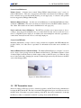
3.4 IR Transmitter tower . . . . . . . . . . . . . .
3.5 Communication . . . . . . . . . . . . . . . . .
.
.
.
.
.
.
.
.
.
.
.
.
.
.
.
.
.
.
.
.
.
.
.
.
.
.
.
.
.
.
.
.
.
.
.
.
.
.
.
.
.
.
.
.
.
.
.
.
.
.
.
.
.
.
.
.
.
.
.
.
.
.
.
.
.
.
.
.
.
.
.
.
.
.
.
.
.
.
.
.
.
.
.
.
.
.
.
.
.
.
.
.
.
.
.
.
.
.
.
.
28
28
28
28
31
32
4
Requirement specification
4.1 Description of the system . . . . . . . . . . . . . . . . . . . . . . . . . . . . . . . .
4.2 Functional requirements . . . . . . . . . . . . . . . . . . . . . . . . . . . . . . . .
4.3 Non-functional requirements . . . . . . . . . . . . . . . . . . . . . . . . . . . . . .
33
33
33
35
5
Choice of COTS
5.1 Choice of programming language . . . . . . . . . . . . . . . . . . . . . . . . . . .
5.2 Hardware considerations - Choice of sensors . . . . . . . . . . . . . . . . . . . . . .
38
38
40
6
Design
6.1 Use cases . . . . . . . . . . . . . . . . . . . . . . . . . . . . . . . . . . . . . . . .
6.2 Deployment diagram . . . . . . . . . . . . . . . . . . . . . . . . . . . . . . . . . .
6.3 Sequence Diagrams . . . . . . . . . . . . . . . . . . . . . . . . . . . . . . . . . . .
42
42
49
51
2
3
Introduction
1.1 Problem description . .
1.2 Scope . . . . . . . . . .
1.3 Research method . . . .
1.4 Motivation . . . . . . .
1.5 Related work . . . . . .
1.6 Introduction to Concepts
1.7 Structure of the report .
.
.
.
.
.
.
.
.
.
.
.
.
.
.
.
.
.
.
.
.
.
.
.
.
.
.
.
.
.
.
.
.
.
.
.
.
.
.
.
.
.
.
.
.
.
.
.
.
.
.
.
.
.
.
.
.
4
CONTENTS
7
HAZOP Analysis
7.1 Description of the HAZOP process
7.2 Results of the HAZOP study . . .
7.3 Discussion . . . . . . . . . . . . .
7.4 Conclusion . . . . . . . . . . . .
.
.
.
.
60
60
63
65
66
8
Fault Tree Analysis
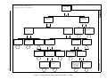
8.1 Fault tree construction . . . . . . . . . . . . . . . . . . . . . . . . . . . . . . . . .
8.2 Analysis . . . . . . . . . . . . . . . . . . . . . . . . . . . . . . . . . . . . . . . . .
8.3 Discussion and Conclusion . . . . . . . . . . . . . . . . . . . . . . . . . . . . . . .
67
67
68
72
9
Construction
9.1 Final deployment . . . . . . . . . . . .
9.2 Communication between physical nodes
9.3 Class diagrams . . . . . . . . . . . . .
9.4 Final sequence diagrams . . . . . . . .
.
.
.
.
74
74
76
77
81
10 Failure Mode and Effect Analysis
10.1 Description of the FMEA process . . . . . . . . . . . . . . . . . . . . . . . . . . .
10.2 Results of the FMEA study . . . . . . . . . . . . . . . . . . . . . . . . . . . . . . .
10.3 Discussion and Conclusion . . . . . . . . . . . . . . . . . . . . . . . . . . . . . . .
84
84
84
85
11 Testing and safety validation
11.1 Safety validation . . . .
11.2 Test plan . . . . . . . . .
11.3 Test results . . . . . . .
11.4 Discussion . . . . . . . .
.
.
.
.
86
86
86
89
91
12 Discussion, Conclusion and Further work
12.1 Discussion . . . . . . . . . . . . . . . . . . . . . . . . . . . . . . . . . . . . . . . .
12.2 Conclusion . . . . . . . . . . . . . . . . . . . . . . . . . . . . . . . . . . . . . . .
12.3 Further work . . . . . . . . . . . . . . . . . . . . . . . . . . . . . . . . . . . . . .
92
92
93
93
A Requirement specification version 1.0
A.1 Description of the system . . . . . . . . . . . . . . . . . . . . . . . . . . . . . . . .
A.2 Functional requirements . . . . . . . . . . . . . . . . . . . . . . . . . . . . . . . .
A.3 Non-functional requirements . . . . . . . . . . . . . . . . . . . . . . . . . . . . . .
95
95
95
97
.
.
.
.
.
.
.
.
.
.
.
.
.
.
.
.
.
.
.
.
.
.
.
.
.
.
.
.
.
.
.
.
.
.
.
.
.
.
.
.
.
.
.
.
.
.
.
.
.
.
.
.
.
.
.
.
.
.
.
.
.
.
.
.
.
.
.
.
.
.
.
.
.
.
.
.
.
.
.
.
.
.
.
.
.
.
.
.
.
.
.
.
.
.
.
.
.
.
.
.
.
.
.
.
.
.
.
.
.
.
.
.
.
.
.
.
.
.
.
.
.
.
.
.
.
.
.
.
.
.
.
.
.
.
.
.
.
.
.
.
.
.
.
.
.
.
.
.
.
.
.
.
.
.
.
.
.
.
.
.
.
.
.
.
.
.
.
.
.
.
.
.
.
.
.
.
.
.
.
.
.
.
.
.
.
.
.
.
.
.
.
.
.
.
.
.
.
.
.
.
.
.
.
.
.
.
.
.
.
.
.
.
.
.
.
.
.
.
.
.
.
.
.
.
.
.
.
.
.
.
.
.
.
.
.
.
.
.
.
.
.
.
.
.
.
.
.
.
.
.
.
.
.
.
.
.
.
.
.
.
.
.
.
.
.
.
.
.
.
.
.
.
.
.
.
.
.
.
.
.
.
.
.
.
.
.
.
.
.
.
.
.
.
.
.
.
.
.
.
.
.
.
.
.
.
.
.
.
.
.
.
.
.
.
.
.
.
.
.
.
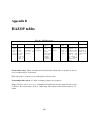
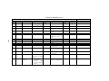
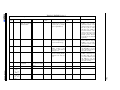
B HAZOP tables
100
C FMEA tables
113
D Source code
116
E User Manual
130
F Glossary
131
G Abbreviations
133
5
List of Figures
1.1
Overview of development process . . . . . . . . . . . . . . . . . . . . . . . . . . .
11
2.1
2.2
2.3
Overview of the risk management process . . . . . . . . . . . . . . . . . . . . . . .
Flow chart of the HAZOP study process . . . . . . . . . . . . . . . . . . . . . . . .
Precedence for safe design . . . . . . . . . . . . . . . . . . . . . . . . . . . . . . .
17
20
24
3.1
3.2
3.3
The LEGO Mindstorms RCX . . . . . . . . . . . . . . . . . . . . . . . . . . . . . .
Infrared Emitter/Detector . . . . . . . . . . . . . . . . . . . . . . . . . . . . . . . .
LEGO Mindstorms IR Tower . . . . . . . . . . . . . . . . . . . . . . . . . . . . . .
29
31
32
4.1
Robot production cell . . . . . . . . . . . . . . . . . . . . . . . . . . . . . . . . . .
34
6.1
6.2
6.3
6.4
6.5
6.6
6.7
6.8
6.9
6.10
6.11
6.12
6.13
6.14
Overall system use case diagram . . . . . . . . . .
Stop CutRob use case diagram . . . . . . . . . . .
Centralized architecture . . . . . . . . . . . . . . .
Decentralized architecture with IR communication
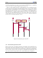
Start when the operator leaves SCZ . . . . . . . . .
Stop when the operator enters SCZ . . . . . . . . .
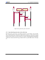
Stop initiated by OFF button connected to SCZ . .
Stop on sensor-RCX battery low . . . . . . . . . .
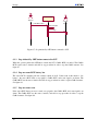
Stop on sensor error . . . . . . . . . . . . . . . . .
Boot sensor RCX . . . . . . . . . . . . . . . . . .
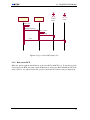
Boot CutRob RCX . . . . . . . . . . . . . . . . .
Shut down sensor RCX . . . . . . . . . . . . . . .
Shut down CutRob RCX . . . . . . . . . . . . . .
Shut down CutRob RCX in centralized system . . .
.
.
.
.
.
.
.
.
.
.
.
.
.
.
44
45
50
51
52
53
54
55
56
56
57
57
58
59
8.1
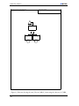
8.2
Main Fault Tree . . . . . . . . . . . . . . . . . . . . . . . . . . . . . . . . . . . . .
Generic Fault Tree . . . . . . . . . . . . . . . . . . . . . . . . . . . . . . . . . . .
69
70
9.1
9.2
9.3
9.4
9.5
9.6
9.7
9.8
Decentralized architecture without IR communication
Use of Emitter-Detector sensor. Taken from [HiT] .
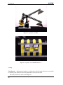
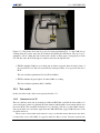
A picture of the robot production cell. . . . . . . . .
Class diagram for Production system . . . . . . . . .
A picture of CutRob . . . . . . . . . . . . . . . . .
A picture of an ON/OFF button box . . . . . . . . .
A picture of the safety critical zone . . . . . . . . . .
Start CutRob when ON button is pushed . . . . . . .
75
77
78
79
80
80
81
82
6
.
.
.
.
.
.
.
.
.
.
.
.
.
.
.
.
.
.
.
.
.
.
.
.
.
.
.
.
.
.
.
.
.
.
.
.
.
.
.
.
.
.
.
.
.
.
.
.
.
.
.
.
.
.
.
.
.
.
.
.
.
.
.
.
.
.
.
.
.
.
.
.
.
.
.
.
.
.
.
.
.
.
.
.
.
.
.
.
.
.
.
.
.
.
.
.
.
.
.
.
.
.
.
.
.
.
.
.
.
.
.
.
.
.
.
.
.
.
.
.
.
.
.
.
.
.
.
.
.
.
.
.
.
.
.
.
.
.
.
.
.
.
.
.
.
.
.
.
.
.
.
.
.
.
.
.
.
.
.
.
.
.
.
.
.
.
.
.
.
.
.
.
.
.
.
.
.
.
.
.
.
.
.
.
.
.
.
.
.
.
.
.
.
.
.
.
.
.
.
.
.
.
.
.
.
.
.
.
.
.
.
.
.
.
.
.
.
.
.
.
.
.
.
.
.
.
.
.
.
.
.
.
.
.
.
.
.
.
.
.
.
.
.
.
.
.
.
.
.
.
.
.
.
.
.
.
.
.
.
.
.
.
.
.
.
.
.
.
.
.
.
.
.
.
.
.
.
.
.
.
.
.
.
.
.
.
.
.
.
.
.
.
.
.
.
.
.
.
.
.
.
.
.
.
.
.
.
.
.
.
.
.
.
.
.
.
.
.
.
.
.
.
.
.
.
.
.
.
.
.
.
.
.
.
.
.
.
.
.
.
.
.
.
.
.
.
.
.
.
.
.
.
.
.
.
.
.
.
.
.
.
.
.
.
.
.
.
.
.
.
.
.
.
.
LIST OF FIGURES
9.9 Stop CutRob when OFF button is pushed . . . . . . . . . . . . . . . . . . . . . . .
9.10 Stop CutRob when movement is detected . . . . . . . . . . . . . . . . . . . . . . .
82
83
11.1 Test Robot . . . . . . . . . . . . . . . . . . . . . . . . . . . . . . . . . . . . . . . .
11.2 Testing with the test robot . . . . . . . . . . . . . . . . . . . . . . . . . . . . . . . .
88
89
A.1 Drawing illustrating the production cell . . . . . . . . . . . . . . . . . . . . . . . .
96
7
List of Tables
2.1
2.2
2.3
Guideword interpretations for PES . . . . . . . . . . . . . . . . . . . . . . . . . . .
Fault tree symbols. . . . . . . . . . . . . . . . . . . . . . . . . . . . . . . . . . . .
Relation between hazard identification techniques . . . . . . . . . . . . . . . . . . .
18
21
23
6.1
6.2
6.3
Short description of main use cases . . . . . . . . . . . . . . . . . . . . . . . . . . .
Centralized vs. decentralized system . . . . . . . . . . . . . . . . . . . . . . . . . .
Physical nodes in system . . . . . . . . . . . . . . . . . . . . . . . . . . . . . . . .
43
49
50
7.1
7.2
7.3
7.4
7.5
7.6
Guidewords used in the HAZOP study.
Consequence values . . . . . . . . . .
Likelihood ranges . . . . . . . . . . .
Risk Class Definitions . . . . . . . . .
Risk classification . . . . . . . . . . .
HAZOP roles . . . . . . . . . . . . .
.
.
.
.
.
.
61
61
61
62
62
62
11.1 Test results . . . . . . . . . . . . . . . . . . . . . . . . . . . . . . . . . . . . . . .
90
B.1
B.2
B.3
B.4
B.5
B.6
B.7
B.8
B.9
B.10
B.11
B.12
B.13
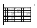
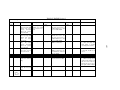
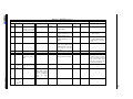
HAZOP template . . . . . . . .
HAZOP Session 1 . . . . . . . .
HAZOP Session 1 . . . . . . . .
HAZOP Session 1 . . . . . . . .
HAZOP Session 2 . . . . . . . .
HAZOP Session 2 . . . . . . . .
HAZOP Session 2 . . . . . . . .
HAZOP Session 2 . . . . . . . .
HAZOP Session 2 . . . . . . . .
HAZOP Session 2 . . . . . . . .
HAZOP Session 2 . . . . . . . .
HAZOP Session 2 . . . . . . . .
HAZOP Session 2 - Control Unit
.
.
.
.
.
.
.
.
.
.
.
.
.
.
.
.
.
.
.
.
.
.
.
.
.
.
.
.
.
.
.
.
.
.
.
.
.
.
.
.
.
.
.
.
.
.
.
.
.
.
.
.
.
.
.
.
.
.
.
.
.
.
.
.
.
.
.
.
.
.
.
.
.
.
.
.
.
.
.
.
.
.
.
.
.
.
.
.
.
.
.
.
.
.
.
.
.
.
.
.
.
.
.
.
.
.
.
.
.
.
.
.
.
.
.
.
.
.
.
.
.
.
.
.
.
.
.
.
.
.
.
.
.
.
.
.
.
.
.
.
.
.
.
.
.
.
.
.
.
.
.
.
.
.
.
.
.
.
.
.
.
.
.
.
.
.
.
.
.
.
.
.
.
.
.
.
.
.
.
.
.
.
.
.
.
.
.
.
.
.
.
.
.
.
.
.
.
.
.
.
.
.
.
.
.
.
.
.
.
.
.
.
.
.
.
.
.
.
.
.
.
.
.
.
.
.
.
.
.
.
.
.
.
.
.
.
.
.
.
.
.
.
.
.
.
.
.
.
.
.
.
.
.
.
.
.
.
.
.
.
.
.
.
.
.
.
.
.
.
.
.
.
.
.
.
.
.
.
.
.
.
.
.
.
.
.
.
.
.
.
.
.
.
.
.
.
.
.
.
.
.
.
.
.
.
.
.
.
.
.
.
.
.
.
.
.
.
.
.
.
.
.
.
.
.
.
.
.
.
.
.
.
.
.
.
.
.
.
.
.
.
.
.
.
.
.
.
.
.
.
.
.
.
.
.
.
.
.
.
.
.
.
.
.
.
.
.
.
.
.
.
.
.
.
.
.
.
.
.
.
.
.
.
.
.
.
.
.
.
.
.
.
.
.
.
.
.
.
.
.
.
.
.
.
.
.
.
.
.
.
.
.
.
.
.
.
.
.
.
.
.
.
.
.
.
.
.
.
.
.
.
.
.
.
.
.
.
.
.
.
.
.
.
.
.
.
.
.
.
.
.
.
.
.
.
.
.
.
.
.
.
.
.
.
.
.
.
.
.
.
.
.
.
.
.
.
.
.
.
.
.
.
.
.
.
.
.
.
.
.
.
.
.
.
.
.
.
.
.
.
.
.
.
.
.
.
.
.
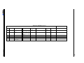
100
101
102
103
104
105
106
107
108
109
110
111
112
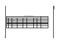
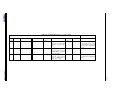
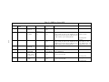
C.1 FMEA template . . . . . . . . . . . . . . . . . . . . . . . . . . . . . . . . . . . . . 113
C.2 FMEA on CutRob RCX . . . . . . . . . . . . . . . . . . . . . . . . . . . . . . . . . 114
C.3 FMEA on Sensor RCX . . . . . . . . . . . . . . . . . . . . . . . . . . . . . . . . . 115
8
Chapter 1
Introduction
This chapter contains a brief presentation of the project, its scope and the research method used.
Information about related work is given in section 1.5, and basic concepts in safety are defined in
section 1.6. The structure of the report is described in section 1.7.
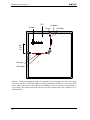
1.1 Problem description
A robot production cell is a closed area where one or more industrial robots (cutting robots, welding
robots etc.) work together. Depending on the current activities performed by each robot, some areas
are safe to enter while others will be unsafe or dangerous. The safety system shall allow people to
enter the safe areas for maintenance and other important activities without interfering with the robots’
work. If a person tries to enter a dangerous area, the robots operating in this area must be turned off
immediately in order to avoid accidents.
The task of this project is to design and implement a prototype of a safety critical robot production
cell where an industrial robot is working. The design and implementation process shall result in a
functioning system, which can later be used for further experimentation. The production cell shall be
implemented as a prototype of the real system using LEGO Mindstorms technology, and the main focus of the development process shall be on safety. Three types of hazard analysis shall be performed:
HAZOP, FTA and FMEA.
The project consists of the following activities:
1. Specification of functional and non-functional requirements including safety requirements
2. Design
The design shall be represented by UML diagrams.
3. Safety analysis
Three safety related activities shall be performed in order to ensure that the final system is safe
enough:
• Identification of risk
What can go wrong and how? This is mainly concerned with the relationship between the
control system, the robot and the person that enters the production cell. HAZOP is the
main tool for this activity.
9
Introduction
• Identify safety and reliability requirements for each component in the system
This activity includes the identification of important firewalls and barriers. FTA is the
most important tool for this activity.
• Analysis of the consequences of component failure in the currently chosen architecture
This shall be done in order to see if all necessary barriers are in place. FMEA is an
important tool for this activity.
4. Construction and coding of the robot production cell, including the LEGO robots and sensors
5. Functional testing and safety validation
1.2 Scope
The intention of this project is not to develop an advanced prototype in LEGO. The project focuses
on the safety aspects of the prototype to be developed. Hence, the scope of our work is to analyze
the requirements and design of the system according to safety, and to use the results of these analysis
in order to achieve an acceptable level of safety. During design, more effort will be put on ensuring
safety than on providing a flexible architecture suitable for extensions.
To view the system as safety-critical, we have chosen to pretend that the simulated industrial
robot presents an actual threat to anyone approaching it. Without this abstraction, an analysis of
safety aspects would be meaningless. This means that even if the prototype is built of LEGO and
thus represents no real threat, consequences as death and injury are used when assessing criticality
of hazards. Thus, the distinction between prototype and real-world in this project is obliterated when
analyzing the system. When considering requirements, limitations of the prototype medium is taken
into account. When analyzing safety, real-world consequences are considered. We considered this
mix of concepts to be necessary in order to solve the problem.
1.3 Research method
This section briefly describes the development activities performed in the project. First, each of the
phases, as well as the connections between them, are described. Then, a discussion of the applicability
of the approach in safety critical systems is presented.
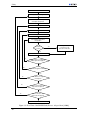
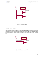
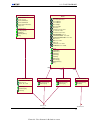
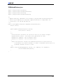
1.3.1 Process description
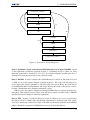
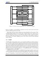
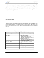
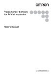
The development process followed in the project is divided into eight phases. All of these are briefly
described below. Figure 1.1 illustrates how each of the phases are related to each other. As indicated
in the figure, the output of some phases may affect documents produced or decisions taken in earlier
phases of the process. For instance, requirements are updated after each hazard analysis. The process
of safety validation is included in several phases; HAZOP, FTA, FMEA and Testing. This is not
indicated in the figure.
Phase 1: Requirements specification The first step is to analyze the system in order to elicit the
requirements. Input to this phase is the problem description, as well as information about the possibilities and restrictions of the development medium, i.e. LEGO Mindstorms. The output of this phase
is a requirements specification.
10
1.3. RESEARCH METHOD
Requirements specification
(1)
(3)
(5)
Construction of UML diagrams
(2)
(6)
HAZOP
(4)
(8b)
FTA
Construction
(8a)
(7)
FMEA
(9)
Implementation
(10)
Testing and safety validation
Figure 1.1: Overview of development process
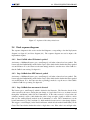
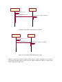
Phase 2: Preliminary design - Construction of UML diagrams to use as input to HAZOP Based
on the requirements specification produced in phase 1, a preliminary design is carried out. Each
functional requirement is described by a use case, and sequence diagrams describing the flow of
information between physical devices in the system are created.
Phase 3: HAZOP In order to identify risks, a HAZOP analysis is carried out. The analysis is based
on UML use cases and sequence diagrams produced in phase 2. The results from this analysis are
used to improve the system requirements to ensure the safety of the system. Hence, the results derived
from HAZOP will affect both requirements and design. Based on the results of this analysis, a choice
between a decentralized and a centralized architecture is made.
UML use cases and sequence diagrams used during HAZOP will not be used later in the development phase. Thus, updated versions of these items will not be created even if the results of HAZOP
introduce the need for changed or additional requirements.
Phase 4: FTA In phase 4, a fault tree analysis is carried out. There are two reasons for performing
this analysis; Firstly, to identify safety and reliability requirements for each component of the system,
secondly, to identify important barriers. Inputs to this phase are the results deduced from the HAZOP
analysis. Identified consequences in HAZOP are used as top-events in the fault tree.
11
Introduction
After this phase, the requirement specification may have to be updated. Furthermore, some results
will be used as inputs to further design.
Phase 5: Construction In this phase, class diagrams and final sequence diagrams are constructed.
These diagrams will be used as input for implementation.
Phase 6: FMEA On the final design, analysis of the consequences of component failure is performed. This is necessary in order to ensure that all important barriers are in place. FMEA is used for
this purpose.
Phase 7: Implementation This phase includes construction and coding of the individual robots,
including actuators and sensors, as well as system integration.
Phase 8: Testing and safety validation This is the final phase. The system is tested, and safety
validation is performed through testing of the safety requirements.
1.3.2 Validation of the process
The approach described above, where only one iteration of each safety analysis is performed, should
not be adopted by others developing safety critical systems. When developing real-world systems,
safety analysis should be repeated each time a change is introduced and all documents updated in
order to reflect the actual system under development [oD00a]. Ideally, the development process should
have followed the life cycle process described in a standard, i.e. IEC 61508. A short introduction to
this standard is given in section 2.5. Strict time limitations made such an approach impossible in this
project, and the approach described above was adopted. The use of this simplified approach can be
justified because of the fact that the system developed presents no real threat to people or environment,
it only simulates a real-world situation. If, however, the prototype should ever be realized as a realworld system, a more thorough development approach must be conducted. In this case the use of only
one iteration will not be sufficient.
Another area for discussion is the choice of which hazard analysis techniques to use. A description
of the three techniques mentioned above (HAZOP, FTA and FMEA), as well as an explanation of the
need to perform hazard analysis, is given in chapter 2. Other techniques for hazard analysis are not
considered in this report since the project was constrained to these methods.
1.4 Motivation
Our motivation for choosing this project is among other things:
• To learn about safety and get practice in conducting safety analysis.
• To get practice designing and developing real-time systems using our theoretic knowledge about
general software engineering.
None of the team members had any experience in any of these two fields, and we liked the idea
of using LEGO Mindstorms for the purpose of learning and experimenting with the combination of
safety and real-time systems.
12
1.5. RELATED WORK
1.5 Related work
No material is found on previous research on the use of LEGO Mindstorms as a prototype medium
for safety-critical systems. However, research is performed on developing a reliable communication
protocol for leJOS and on the suitability of using LEGO in education. Regarding safety, one area of
research is on the use of UML in safety related work.
Currently, work on providing leJOS with a reliable communicating system is performed [Legb].
This work is a successor of a project developing a reliable communication protocol for communication
between the RCX and the IR tower. However, a known bug to the software developed in the project
is that the protocol is very slow [Lega]. Furthermore, the protocol does not allow communication
between two RCXs.
[Knu00] mention the value of LEGO as a tool for teaching a variety of topics, including robot construction, real-world programming and artificial intelligence. LEGO Mindstorms is used for teaching
purposes at a wide range of levels, from primary schools to universities. Among these are Duke,
University of Southern California, Lawrence Technological University and Universitat Osnabruck
[Knu00]. Research on the potential of using LEGO Mindstorms for introducing young people to the
science of computer programming is currently performed at the University of Glasgow [dcs].
Some research has been carried out on the use of UML in safety related work. An example is found
in [HG02], which discusses how patterns and UML can be utilized in a safety related system. The
approach described includes the conduct of a hazard analysis based on sequence diagrams describing
the flow of information in use cases. One use case is created for each requirement, and FTA is used as
hazard analysis. In [WSS99], the use of UML use cases as input to a HAZOP analysis on an airplane
landing system is described. Other projects and research where UML is integrated with safety are
described in [Hau01]. More research on the use of UML is conducted in the area of security-critical
systems. [BDF+ 02] and [HBLS02] define a UML profile for risk assessment, extending the UML
standard with stereotypes and rules for specialized diagrams.
1.6 Introduction to Concepts
To give the reader some background for reading the rest of the report, definitions of the main safety
concepts are included in this section.
Safety - Safety is freedom from accidents or losses. [Lev95, p.181]
Hazard - A hazard is a state or set of conditions of a system that, when combined with certain
environmental conditions, inevitably will lead to an accident [Lev86, Lev95]
Risk - Risk is a combination of the frequency or probability of a specified hazardous event, and
its consequence [Sto96, p.60].
Safety critical system - A safety critical system is a system that by failing can cause harm to life,
property or environment [WSS99].
Safety related system - The term ”Safety related systems” is in this report used as a synonym for
safety critical systems. It is some times used to describe a system of lower criticality than a safety
critical system.
13
Introduction
1.7 Structure of the report
The report consists of 12 chapters, each of which are listed below.
Chapter 1: Introduction: provides information about the project, its scope, description of the
research method followed, motivation and an introduction to concepts. Furthermore a description of
the report structure is included.
Chapter 2: Safety: contains a brief introduction to subjects related to the development of safety
critical systems. This includes an introduction to hazard analysis and the management of risks, including principles for safe design. Furthermore, criterias for choice of programming language and a
brief introduction to standards are given.
Chapter 3: Technical Context - LEGO Mindstorms:
the project prototype.
presents the technical equipment used in
Chapter 4: Requirements Specification: describes the prototype’s requirements. Both functional
and non-functional requirements are presented, including safety requirements.
Chapter 5: Choice of COTS: explains the choice of COTS used in the system, both the choice of
programming language and the choice of hardware components.
Chapter 6: Design: presents the preliminary design of the system through use case descriptions
and use case diagrams, deployment diagrams and sequence diagrams.
Chapter 7: HAZOP Analysis:
describes and evaluates the HAZOP study performed on the system.
Chapter 8: Fault Tree Analysis:
system.
Chapter 9: Construction:
describes and evaluates the fault tree analysis performed on the
contains class diagrams and final sequence diagrams.
Chapter 10: Failure Mode and Effect Analysis:
formed on the system.
describes and evaluates the FMEA analysis per-
Chapter 11: Testing and Safety Validation: presents the test plan, the test results and the corrections done to the system based on the test results.
Chapter 12: Discussion, Conclusion and Further work:
sults in this project and discusses areas for further work.
The report also consists of several appendices:
14
evaluates and summarizes the main re-
1.7. STRUCTURE OF THE REPORT
Appendix A: Requirements specification version 1.0: Version 1 of the requirements specification.
UML use cases and sequence diagrams used as input to HAZOP are based on this version of the
requirements.
Appendix B: HAZOP tables
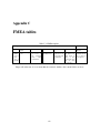
Appendix C: FMEA table
Appendix D: Source code
Appendix E: User Manual
Appendix F: Glossary
Appendix G: Abbreviations
Appendix H: Bibliography
15
Chapter 2
Safety
This chapter provides a brief introduction to subjects related to the development of safety critical
systems. Emphasis is put on the risk management process. In addition to this, criterias for the choice
of programming language and a brief presentation of safety standards, are included. The chapter
will give the reader an introduction to the methods applied during development of the prototype.
Terminology connected to hazards analysis is not included in this part, and the reader is referred to
appendix F for a definition of the expressions used.
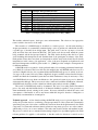
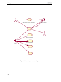
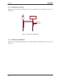
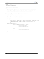
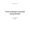
An outline of the risk management process is presented in figure 2.1. The process is iterative and
consists of seven phases, of which five are sequential and two are parallel. During the first phase the
context for the risk analysis is defined. In this phase the system is described and acceptance criteria
and constraints defined. The two following phases partly overlap, and are described in section 2.1. The
fifth phase in the risk management process concentrates on the acceptance criteria, where each risk is
evaluated against the acceptance criteria defined in phase 1. Basic principles for safe design used to
treat risk are presented in section 2.3. All phases iterate both with the other phases and themselves,
and the whole process iterates through the monitor and review activity [Hou02]. When all relevant
risks are accepted, development can proceed with further design and implementation.
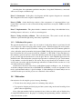
2.1 Hazard analysis
Hazard analysis is seen as a necessary first step to eliminate or control potential hazards of a system.
Once hazards are identified, their importance can be assessed and appropriate steps may be taken to
remove them or to mitigate their effects. In some cases, simply knowing that a hazard may exist may
provide sufficient information to eliminate or control it. In other cases, in-depth analysis of the causes
of the hazard is required. In either case the result of the analysis must be documented and used in the
further development of the system [Sto96].
Existing techniques for performing hazard analysis on a system differ according to different dimensions [Hau01], e.g. depth of analysis, way of conducting analysis, whether they are quantitative or
qualitative, and search method used. Which method to use, must be decided for each specific project.
It is often advantageous to use a combination of different methods, since each method provides different information about the system under consideration. Thus, use of different techniques might make
it easier to both discover new hazards (bottom-up approaches) and find causes for specific hazards
(top-down approaches).
Hazard analysis should be performed continuously throughout the development of a system, with
increasing depth and extent as more information is obtained about the system under consideration.
16
2.1. HAZARD ANALYSIS
Identify Context
Identify Hazard
Determine
Likelihood
Determine
Consequence
Monitor and Review
Communicate and Cons ult
Analyze Hazard
Estimate Level of Risk
Evaluate Risks
Accept Risks
Yes
No
Treat Risk
Figure 2.1: Overview of the risk management process. Modified from [Sta99].
However, an emphasis on early identification of hazards is necessary so that corrective action can be
taken before final design decisions are made.
Below, three of the most common techniques for hazard identification will be presented. These
are HAZOP, FMEA and FTA, and all of these will be conducted in this project. The first two use
a bottom-up approach, the latter a top-down approach. A guide for when to use the three methods
and how to combine them is given in section 2.1.4. The description of the techniques is meant as a
brief introduction to the methods. [IBN96] provides a short overview of these and other established
analysis techniques.
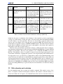
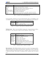
2.1.1 HAZOP
A HAZOP (Hazard and Operability) study is a bottom-up hazard identification technique which purpose is to identify potential hazards and operability problems caused by deviations from design intent.
The method was originally developed within the chemical industries in the early 1960s and was later
approved upon and published by the Chemical Industries Association in London. Since then, the technique has been adopted by other industries and the introduction of software-based systems in control
applications has necessitated transfer to the field of software engineering. In the UK, The Ministry of
Defence has developed a standard explaining how to conduct HAZOP studies for systems including
programmable electronic systems (PES).
A HAZOP study typically requires several HAZOP study meetings and should be carried out by
a team possessing broad knowledge of the system and its operation. The optimal size of this team is
5 to 7 and should include a leader with experience in HAZOP analysis and a technical secretary that
takes care of documentation, as well as experts on all parts relevant to the system under consideration.
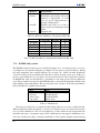
17
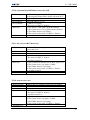
Safety
Guide word
No
More
Part of
Other than
Eary
Late
Before
After
Example Interpretation for PES
No data or control signal passed.
More data is passed than intended.
Incomplete data or control signals.
The data signals are complete but incorrect.
The signal arrives too early with reference to clock time.
The signal arrives too late with refernce to clock time.
The signal arrives earlier than intended within a sequence.
The signal arrives later than intended within a sequence.
Table 2.1: Example guideword interpretations for PES [oD00b].
This includes technical experts, developers, users and maintainers. The selection of an appropriate
team is critical to the success of the study.
The execution of a HAZOP study is described as a creative process. At each study meeting a
design representation is systematically examined using a series of guidewords, which each describes
a specific type of deviation from design intent. The guide word is used as a prompt, to focus the
study and elicit ideas and discussion [RCC99]. The guide words chosen must match the system
being examined and the design representations. The study leader should produce the list of guide
words including their interpretations and distribute them to the participants in advance of the study.
Each guideword may have more than one interpretation and the study leader should list all relevant
interpretations in the context of its application. A list of the most frequently used guidewords and
their usual interpretation in PES is given in table 2.1. [oD00b] provides examples on interpretations
for different attributes.
A HAZOP study is recognized to be the preferred method of conducting preliminary hazard analysis [oD96]. For systems in the lowest risk class this might be the only HAZOP study necessary. For
systems in a higher risk class it is recommended that the HAZOP study process is carried out at various stages of the system’s life cycle; When a high-level design is available, when a detailed design is
available and when the documented system has been built. Furthermore, it may be necessary to carry
out a HAZOP study in cases when a modification to the operational system is proposed or when the
environment has changed. This is necessary in order to refine and extend the identification of hazards.
A HAZOP study should be used in conjunction with the safety analysis activities [oD00a].
The result of a HAZOP study must be documented. The style of recording shall be determined
prior to the study and shall include details of all hazards identified, regardless of any protection or
alarm mechanisms already existing in the system. Necessary information include the causes and
consequences of the hazard, as well as any means within the design for detection of mitigation or
alternatively recommendations for mitigation.
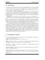
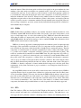
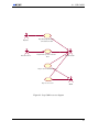
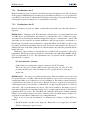
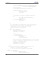
Technical approach A flow chart describing the HAZOP study process is given in figure 2.2. Basically, the procedure involves considering a design representation of the system and systematically
questioning every part of it in order to establish how deviations from the design intent may arise. Each
component of a system and each interconnection between components possesses one or more entities,
which each possesses one or more attributes. The study team should consider each attribute in turn.
The process is carried out as a structured brainstorming using the list of predefined guidewords. Each
relevant guideword is applied to each attribute so that the search for deviations is carried out in a
18
2.1. HAZARD ANALYSIS
structured manner. When all relevant guide words have been applied to the given attribute the other
attributes of the entity under consideration are examined in turn. Later, the rest of the entities are
considered the same way. In cases where a possible deviation is found when applying a guideword
to an attribute the study team investigates the causes and consequences as well as the protection or
indication mechanism of the deviation. When assessing whether deviations and their consequences
might have a negative effect on the safe and efficient operation of the system, one should not take any
credit for protective systems or instruments which are already included in the design [Lih]. However,
after assessing consequences, protective systems already included in the design must be considered to
check whether they are adequate.
2.1.2 FMEA
FMEA (Failure Modes and Effects Analysis) was formally introduced with the introduction of the
US military standard MIL-P-1629 in the late 1940s. It was used for aerospace development to avoid
errors on small sample sizes of costly rocket technology [Inc]. FMEA was then reintroduced in the
1970s when Ford Motor Company used it in the automotive field. Now it has become mandatory
with QS9000, which is the automotive analogy to the iso standard ISO9000. More information about
FMEA and this standard can be found in [Smi].
FMEA is a bottom-up approach for identifying hazards in a technical system. It requires thorough
knowledge of the system under consideration, both of its components and its requirements. The system is divided into subsystems, which should all be identified before starting the analysis. Then the
components of each subsystems are analyzed systematically in order to find possible failure modes,
i.e. possible ways in which a component could fail to perform its desirable function [fmea]. The
results are systematically documented in a tabular FMEA form. For each component, all possible operational states, e.g. open/closed, active/non-active, are considered. For each identified failure mode,
the possible causes and consequences, or failure effects, are identified, and alternative countermeasures are proposed. Both local and global effects should be considered. The former includes effects
that only affect the unit being analyzed, the latter also affects other units in the system. The purpose
of FMEA is to identify components or features which should be improved to meet the given safety
requirements of the system, and in turn to propose activities to avoid dangerous situations from occurring [fmeb].
By using FMEA, failures in the system will be detected early in the construction phase. FMEA is
especially effective if used on systems where a failure in a system component is the most likely cause
of the system failure [Rau91]. However, the fact that the FMEA method analyzes each and every
part of the system, makes this form of risk analysis very complex. All failure modes with its causes
and effects are to be documented for each component, even if the effects are not critical. This means
a lot of useless documentation. Also, since the focus of the analysis is on failures in the technical
components, the human and procedural failures are easily forgotten in this risk analysis approach.
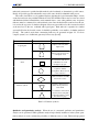
2.1.3 FTA
Fault Tree Analysis (FTA) was developed by Bell Telephone Laboratories in 1962 and is one of
the most widely used methods in system hazards and reliability analysis. The method uses a topdown approach and is primarily a means for analyzing causes of threats, not identifying threats. An
19
Safety
Start
Explain overall design
Select interconnection or component
and explain design intent
Select entity
Select attribute
Select guide word
Select attribute-guide-word
interpretation
Deviation
possible?
Yes
Investigate causes,
consequences and
protection or indication
No
Document
No
All interpretation for combination of
attribute-guide-word applied?
Yes
No
All guidewords applied to attribute?
Yes
No
All attributes of entity
investigated?
Yes
No
All entities on interconnection/
component investigated?
Yes
No
All interconnections and
components investigated?
Yes
End
Figure 2.2: Flow Chart of the HAZOP Study Process. Adopted from [oD00a].
20
2.1. HAZARD ANALYSIS
undesired system state is specified and the method works backwards to determine its possible causes.
Ideally, all possible ways the undesirable event could occur, should be identified in the process.
The result of an FTA is a set of graphical displays depicting the logical interrelationships of basic
events that can lead to the predefined undesired event. The identified causes may be events associated
with hardware failures, human failures, environmental factors or any other pertinent event. A separate
fault tree must be constructed for each undesired event. Once the undesirable event has been chosen,
it is used as the top event of a fault tree diagram. Necessary preconditions for this event are described
at the next level of the tree, combined with logical gates. Each subnode is expanded in a similar
way until all leaf nodes describe events of calculable probability or are unable to be further analyzed
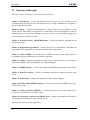
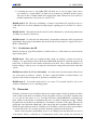
[Lev86] . The symbols used when constructing fault trees are presented in figure 2.2. For more
complex systems, use of additional gates may be necessary [Lev95].
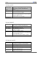
Symbol
AND gate
Logical gates
OR gate
Meaning
Output occurs only if all
inputs occur.
Output occurs if at least one
of he inputs occur.
An event that results from a
combination of events
through a logic gate.
States
Basic event
Undeveloped event
Transfer down
Transfer symbols
Transfer up
A basic fault event that
requires no further
development. These are leaf
nodes in the tree.
A fault event that is not fully
traced to its source.
Transfer symbol used for
further development in a
cause-chain.
Used when the same branch
is involved in several paths
and when the fault tree spans
more than one page.
Table 2.2: Fault tree symbols.
Qualitative and quantitative analysis When the tree is constructed qualitative and quantitative
analysis can be performed. While qualitative analysis helps identify weaknesses in the system, quantitative analysis is used to estimate the probability of different events to occur. The knowledge gained
21
Safety
through analysis is used in order to delineate high-level requirements for safety [Lev86] and may be
used to decide whether it is necessary to introduce safeguards or barriers to prevent a specific failure
to occur.
Both qualitative and quantitative analysis use the concept of a minimal cut set, that is the set of
basic events that cannot be reduced in number for the top-event to occur. To identify this set the fault
tree is reduced to a logically equivalent tree showing the intersections of basic events sufficient to
cause the top event. This means that intermediate events are removed from the tree.
Qualitative analysis evaluates the minimal cut set according to the number of events necessary for
the top-event to occur, as well as according to the type of events involved. [Rau91] categorizes events
involved in three groups: human error, failure of active equipment and failure of passive equipment,
ranked in the order of decreasing criticality. Quantitative analysis can only be performed in cases
where it is possible to estimate the probability of basic events. Applying probabilities to the events
in the minimal cut set allow calculations of the probability for the top-event to occur. A detailed
description of how to perform quantitative analysis on fault trees is given in [Rau91].
Software FTA FTA can also be applied to software. In that case, a fault tree is built based on the
system’s source code. The analysis can be performed on undesirable conditions to determine conditions that need to hold for the undesirable condition to occur. The starting point for the analysis
is the point in the code that performs the potentially undesirable outputs. The code is then analyzed
by deducing how the program can reach that point with the set of values producing the undesirable
output. The analysis is used for verification, as the code must have been written in order to generate
the trees [Lev95].
Advantages and limitations
The following list some of the advantages and limitations of FTA.
Advantages[Cen]:
• Factors external to hardware, software or process can be incorporated into the analysis. This is
an advantage over bottom-up approaches that do not take human and environmental factors into
account.
• FTA only considers relevant failure modes.
• The graphical representation of the fault tree provides an understandable representation of fault
relationships and facilitates the identification of critical factors.
Limitations:
• Unexpected causes will not be included in the analysis.
• The method assumes independence of events when performing probability calculations, an assumption that is not always correct.
• The quality of the output is critically dependent on the expertise of the analysts.
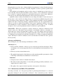
2.1.4 Relation between FMEA, FTA and HAZOP
According to [Lev95], one of the greatest problems in performing hazard analysis is to select the
appropriate technique for the system under consideration. Since each method provides a different
22
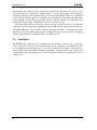
2.2. RISK ESTIMATION AND EVALUATION
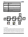
To →
↓ From
HAZOP
FTA
FMEA
HAZOP
FTA
FMEA
HAZOP identifies hazards
at different levels of abstraction.
Hazards identified by HAZOP are inserted in fault
trees based on abstraction
level and the relationships
between the hazards.
A fault tree may be part of
another fault tree, i.e. the
top incident of one fault
tree may be a causing incident in another fault tree.
The analysis of a failure
mode in FMEA may identify a scenario leading to
an unwanted hazard. This
may represent a path in the
fault tree.
Hazards identified by HAZOP may be understood as
failure modes and considered as starting points for
FMEA.
Basic events (leaf nodes)
in the fault tree may be understood as failure modes
and considered as startingpoints for FMEA.
Basic failure modes may
lead to hazards that are basic failure modes in another FMEA.
A basic event (leaf node)
in the fault tree may correspond to a subsystem on
which HAZOP may be applied.
A failure mode in FMEA
can associate a subsystem
on which HAZOP can be
applied.
Table 2.3: Relation between hazard identification techniques [BDF + 02].
insight into the system, a combination of the techniques is often required to provide a comprehensive
coverage of possible hazards. Usually, the results of bottom-up approaches like HAZOP and FMEA
are used as input to top-down approaches. However, it is also possible to apply the methods in the
opposite order. An example of use of this approach is described in [BDF +02], where the leaf nodes
of the fault tree are applied as input to a HAZOP and FMEA analysis. The relation between the three
hazard analysis techniques presented in this report, with emphasis on how they can be applied as
input/output to each other, is given in table 2.3.
There has been performed little experimental evaluation of different hazard analysis techniques.
One experiment concludes that if a compromise between HAZOP and FMEA has to be made, HAZOP
should be chosen [Fal97]. However, some guidelines for use of HAZOP and FMEA are given in
[RCC99]. The guideline consists of a number of questions about the design representation of the
system under consideration. Applying these questions to the design may help decide which method is
most appropriate to use, or possibly how to combine them to achieve a thorough understanding of the
system. In essence, the main advice is that HAZOP only should be applied in cases where failure can
arise through the interactions between components, while FMEA should only be conducted in cases
where information about possible failure modes of components and sub-systems involved is available.
Often, the use of HAZOP before an FMEA results in a more focused and efficient FMEA since failure
modes found during FMEA may be ignored if they have been identified as non-hazardous during a
HAZOP.
2.2 Risk estimation and evaluation
For each identified hazard, the associated risk should be estimated. This analysis consists of two
phases: consequence evaluation and frequency evaluation. The objective of the first activity is to
analyze and evaluate the consequence of an identified hazard. The objective of the latter activity is to
23
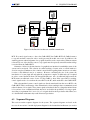
Safety
HAZARD ELIMINATION
Substitution
Simplification
Decoupling
Elimination of human errors
Reduction of hazardous materials or condtions
HAZARD REDUCTION
Decreasing cost
Increasing effectiveness
Design for controllability
Barriers
Lockins
Lockouts
Interlocks
Failure minimization
Safety Factors and margins
Redundancy
HAZARD CONTROL
Reducing exposure
Isolation and containment
Protection systems and fail-safe design
DAMAGE REDUCTION
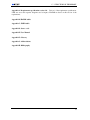
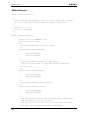
Figure 2.3: Precedence for safe design [Cora].
analyze and evaluate the frequency of the risk. Frequencies can be evaluated based on historic data,
simulations or subjective opinions. Often, FMEA is applied for consequence evaluation, while FTA
is applied for frequency evaluation [BDF + 02].
When the consequence and frequency have been estimated, the two values should be combined
into an estimate for the level of risk for each hazard. This is often done by using a risk matrix that
displays rules for assigning risk values for different combinations of frequencies and consequences.
An example of a risk matrix is given in table 7.5. If one or both values are qualitative, the risk value
should be ranked category values. If both are numeric values, the values should be multiplied.
Based on the estimated risk value, a risk is either accepted or not. If a risk is accepted, it is given
the lowest priority and will not be further evaluated. Risks that are not accepted, are assigned a higher
priority [BDF+ 02].
2.3 Treating risk - principles for safe design
In order to deal with hazards identified during analysis, the design should incorporate basic principles
for safe design. Ideally, all potential hazards should be eliminated, producing a system that is intrinsically safe. However, as achieving total safety is usually impossible, principles for hazard elimination
must be complemented with other techniques. In figure 2.3, options for safe system design are listed
in the order of precedence that is standard for system safety [Lev86], [Lev95], [Corb]. The figure provides an overview of different techniques used in each of the four safety options. The four approaches
are complementary.
Below, a short introduction to each of the four methods are included. For more information on
approaches or techniques belonging to these approaches, the reader is referred to [Cora]. In addition
to applying principles for safe design, specific safety constraints can be placed on system software or
hardware and on human operators.
24
2.3. TREATING RISK - PRINCIPLES FOR SAFE DESIGN
Any hazards that cannot be fully resolved within the system-level design must be traced down
to component requirements, such as software requirements. This traceability is very important, as it
is the only way to ensure that remaining hazards are eliminated or controlled within the context of
individual components [Corb]. Thus, safety will frequently impose constraints on component design
and implementation.
Hazard elimination Hazard elimination is the least expensive and the most effective way of removing hazards. Techniques for achieving this includes substitution, simplification and reduction
of hazardous materials or conditions. One example of substitution is to use simple hardware protection mechanisms instead of a computer, which necessitates greater complexity, to enforce safety
constraints. Simplification applies to both software design and the use of a programming language that
encourages the production of simple and understandable programs. Choice of programming language
is further discussed in section 2.4. Reduction of hazardous materials is achieved by only including
code that is absolutely necessary to achieve the required functionality. Elimination of unused code
has implications for the suitability of using COTS in safety critical systems [Lev95]. Additional functionality and code may lead to hazards and make software hazard analysis more difficult. According
to Leveson, reuse may decrease safety because of the complacency it engenders and because the specific hazards of the new system were not considered when the software was originally designed and
constructed. [Lev95].
Hazard reduction The preferred alternative to hazard elimination is to prevent or minimize the
occurrence of hazards, i.e. reduce the frequency with which the hazard is expected to occur. This can
be achieved by designing the system for controllability or through the use of barriers. The first includes
the use of feedback to allow corrective actions to be performed before significant damage is done. The
latter approach involves introducing a barrier between the hazards and the potential victims. A barrier
may prevent dangerous operations from being performed unless it is safe (interlocks) or keep people
away from dangerous parts of the system until it has become safe (guards). Interlocks use sensors
to detect the state of the system in order to detect dangerous conditions while guards use actuators
to prevent exposure to danger. An example of guards is the use of automatic barriers on railway
crossings. In cases where a barrier is identified to ensure safety, the barrier should be included in the
safety requirements of the system.
Hazard control The third option is to control the hazard if it occurs, i.e. reduce the likelihood of
the hazard leading to an accident. This is achieved by using some form of automatic safety devices
[Lev86]. Limiting exposure includes coding principles stating that critical flags and conditions should
be written as close as possible to the code they protect. Furthermore, systems should always start out
in a safe state. An example of isolation and containment is physical barriers such as concrete walls.
Examples on protection systems and fail-safe designs are watchdog timers that time software to see if
it appears to have gone dead.
Damage reduction Damage minimization may take the form of warning devices, procedures and
training to help personnel react to hazards [Lev86].
25
Safety
2.4 Choice of programming language in SCS
Choice of programming language is regarded as a key issue when implementing safety-related systems
[Sto96]. Some languages offer safety enhancing language features, such as good-exception handling
mechanisms, while others have been found to be particularly error prone. A programming language
that is not only simple itself, but encourages the production of simple and understandable programs
should be used. [Sto96] describes three aspects to consider in choosing a language. Each of these
factors are briefly described below.
Characteristics of the language Carré [Sto96] has identified several characteristics of a programming language that has implications for the safety of the system:
• logical soundness: is there a sound, unambiguous definition of the language?
• complexity of definition: complexity in the definitions of the language features result in complexity within compilers and other support tools, which can lead to errors.
• expressive power: can program features be expressed easily and efficiently?
• security and integrity: can violations of the language definitions be detected before execution?
• verifiability: does the language support verification?
• bounded space and time requirements: can it be shown that time and memory constraints will
not be exceeded?
Even a programming language that is developed specifically for use in critical applications may not
be an ideal language when analyzed with respect to these characteristics. This is because many of the
above factors are in conflict, like having great expressive power often makes the language complex,
which increases the problems of verification and security. Even though no programming language is
”safer” than others (because only the program they produce may have this attribute), some languages
are more suitable than others for the production of critical software because they make it easier to
produce dependable code.
Availability and quality of support tools It is also important to consider the development tools
available to support a language. Especially, the quality of the compiler is an important issue. [Sto96]
states that for safety-critical systems, validation should be seen as a necessary requirement of the
compiler. A validation of a compiler is a process that is performed to determine conformity to the
language standard and such validation does not guarantee the correctness of the code generated by the
compiler.
Expertise within development team Programmers that are familiar with a programming language
are likely to make fewer mistakes and be more productive in this language, and this must be taken into
consideration when selecting a programming language.
26
2.5. STANDARDS FOR DEVELOPING SCS
2.5 Standards for developing SCS
A number of standards exist to guide the development of safety-critical systems. In the UK, the Ministry of Defence (MOD) has published a draft standard on the procurement of safety-critical software
in defence equipment (MOD 00-55) as well as an accompanying standard on HAZOP studies on systems containing programmable electronics (MOD 00-58). The standard establishes a set of procedures
and technical requirements for the development of safety critical software. In the USA, the MIL-STD882B standard, describes the system safety requirements of the U.S. Department of Defense (DOD)
in management, system design and software [IBN96]. Another widely used standard is the generic
standard IEC 61508 from The International Electrotechnical Commission (IEC). The standard covers aspects that need to be addressed when electrical and/or electronic and/or programmable devices
are used to carry out safety functions. The strategy of the standard is to derive safety requirements
from a hazard and risk analysis and to design the system to meet those safety requirements, taking all
possible causes of failure into account. The essence is that all activities relating to functional safety
are managed in a planned and methodical way, with each phase having defined inputs and outputs
[Bro00]. The approach of the standard is based on safety functions, i.e. actions that are required to
ensure that the risk associated with a particular hazard is tolerable. Each safety function is specified in
terms of its functionality (action required) and is assigned an appropriate safety integrity level (SIL).
The safety integrity level reflects the importance of correct operation, and determines the required
methods of design and implementation used for the system [Tho02]. More information on IEC 61508
can be found in [Bro00], [HKB99], [Bel99] and [Kro00].
27
Chapter 3
Technical context - LEGO Mindstorms
LEGO Mindstorms is the result of a collaboration between LEGO and the Massachusetts Institute
of Technology (MIT). The work, which started in 1986, lead to the development of a programmable
brick, a small unit capable of connecting to the external world through a variety of sensors and actuators [FGH+ 02]. Adding these computerized bricks, motors and sensors to the traditional plastic
bricks made it possible to design LEGO robots that could interact with the surroundings. Since 1998,
the LEGO Mindstorms Robotics Invention System (RIS) has been available for commercial use.
The following sections give a short introduction to the main elements of LEGO Mindstorms.
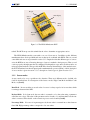
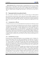
3.1 RCX Brick: The Robotics Command eXplorer
The Robotic Command eXplorer (RCX) brick (see figure 3.1) is the kernel of any Mindstorms robot
and is capable of interacting with the physical world through sensors and motors. The RCX brick
encloses a tiny computer based on a Hitachi H8 series microcontroller. The microcontroller chip also
contains 16 kB of ROM and 32 kB of RAM, 3 input ports that can accept a variety of LEGO sensors,
three output ports used to control actuators (controllable devices), one infrared port and one speaker,
as well as circuitry to provide for limited user interaction. The latter consists of an LCD, which can be
used to indicate the internal state of the RCX brick, and four buttons; On-Off, Run, Prgm and View.
The RCX is powered by six AA batteries.
3.2 Motors
Motors represent the actuators in LEGO Mindstorms and can be attached to the output ports of the
RCX. Two 9-volt motors are included in the RIS kit. The power level of the motors range from 0 to
7. By decreasing the power to a motor however, the output gets weaker.
Actuators are used to respond to stimuli. In most cases the stimulus is obtained from the environment via sensors.
3.3 Sensors
Sensors are used to obtain stimuli from the environment and are the only link with the outside world.
The stimuli are sent to the RCX through the RCX’s input ports, to which the sensors need to be at28
3.3. SENSORS
IR port
LCD display
Sensor
inputs
RUN
button
Motor
outputs
Figure 3.1: The LEGO Mindstorms RCX
tached. The RCX can process this stimuli data in order to determine an appropriate action.
The LEGO Mindstorms kits come with a core set of four sensors. In addition to this, different
manufacturers have developed additional sensors that can be combined with LEGO. The core set and
some additional sensors are presented in section 3.3.2. Despite the fact that different types of sensors
exist, the RCX has no way of knowing what type of sensor is attached to the input ports. Thus, to read
a sensor properly, the input must first be configured. Each input has a type and a mode that can be set
using appropriate methods. The type tells the RCX the electrical characteristics of the attached sensor,
the mode determines how the raw input signal is mathematically processed [Knu]. A brief description
of sensor modes is given in section 3.3.1, a description of sensor types is given in section 3.3.2.
3.3.1 Sensor modes
A sensor needs to be set to a specific mode to function. There are 8 different modes, of which only
6 will be described here. For descriptions of the last two modes, Edge Count Mode and Pulse Count
Mode, see [Bau00].
Raw Mode In raw mode the processed value of a sensor is always equal to its its raw value, which
is an integer between 0 and 1023.
Boolean Mode In boolean mode, the raw value is converted to a boolean value using a parameter
called the sensor slope. The value of this parameter can be from 0 to 31, and determines how the raw
value is converted. More details on the conversion process can be found in [Bau00].
Percentage Mode If a sensor is in percentage mode, the raw value is converted into a value between
0 and 100. High percentage values corresponds to low raw values.
29
Technical context - LEGO Mindstorms
Rotation Mode The rotation mode is only useful for the rotation sensor. The resulting value from
rotation mode is a cumulative rotation in increments of 22.5 degrees [Bau00].
Celsius and Fahrenheit Modes When using Celsius and Fahrenheit modes, raw values are converted into a Celsius temperature. When the Fahrenheit mode is used, the processed value needs to be
converted from Celsius to Fahrenheit.
3.3.2 Sensor types
This section gives a brief introduction to sensors available with LEGO. As mentioned above, the
LEGO Mindstorms kits come with a core set of four sensors. Since these sensors are limited in their
usefulness, some additional sensors available for use with LEGO will be described as well.
Core set of sensors
The core set of sensors available with LEGO Mindstorms include a light sensor, a touch sensor, a
rotation sensor and a temperature sensor. These are briefly presented below.
Light Sensor The light sensor can be used to distinguish between dark and light (e.g. if the light in
a room is turned on or off), to determine different colors of objects, or even to follow a line. The logic
behind this is the reflection of light from objects, which varies depending on their darkness. Dark
objects absorb more light than light objects, and therefore also reflects more light. To measure the
intensity of the reflected light, a small lens is attached to the front of the light sensor. In addition,
the light sensor consists of a red Light Emitting Diode (LED) and a phototransistor that responds to
incoming light [Bau00]. Not only does the sensor detect human visible light, it is also capable of
detecting IR light. The light sensor is in a percentage mode, where the scale goes from 0 (darkest) to
100 (brightest). The values from 40 to 60 is the most typical values.
Touch Sensor The touch sensor can be used as a switch (e.g. for turning a motor on or off), to detect
if a robot hits an obstacle etc. It is the most basic sensor available for LEGO, and consists of a small
push button built onto the end of a 2x3 brick. Both depress and release of the switch is detected, and
when in touch sensor mode, or boolean mode, giving the values 0 or 1.
Rotation Sensor The rotation sensor can be used to determine how much an axle has turned. The
axle is inserted into a hole in the middle of the rotation sensor brick. The relative rotation is measured
in increments of 22.5 degrees, which means that a rotation of 22.5 degrees gives a value of 1, while a
full rotation gives a value of 16 (360/22.5). An example of how the accuracy of measurement can be
increased by using gear reduction is described in [Bau00]. The rotation sensor is not part of the RIS.
Temperature Sensor The temperature sensor measures temperatures in Celsius or Fahrenheit, and
ranges from -20o C to +70o C and -3o F to +157o F. As with the rotation sensor, the temperature sensor
is not included in the RIS. More information on this sensor can be found in [Bau00].
30
3.4. IR TRANSMITTER TOWER
Sensors from Mindsensors
Distance Sensor A distance sensor named ”Sharp GP2D12 infrared distance sensor” can be obtained at Mindsensors. This sensor can precisely and reliably read distance from 10cm up to 80cm,
but it consumes more power than the RCX-active port can supply [tea]. A solution to this problem
has been suggested by Philippe Hurbain [Phi]
Reflective Obstacle Detector Another sensor from Mindsensors is the Infra Red Reflective Obstacle Detector (IRROD01). This sensor can detect an obstacle in front of the RCX within a distance of
20 to 30cm. More details can be found on the Mindsensors web page [tea].
Passive and Active Sensor Multiplexer The RCX has only three sensor input connectors, but according to [tea], the passive multiplexer lets you connect three Boolean sensors (touch sensors) at a
time to a single RCX sensor input port. In addition, the active multiplexer offers the opportunity to
connect three Actively Powered sensors to each single input port.
Sensors from HiTechnic
HiTechnic manufactures a range of sensors, many of which are compatible with LEGO Mindstorms
products. Below, one of the sensors is presented. For information about other sensors available, see
[HiT].
Infrared Emitter/Detector (Model AC1060) The Infrared Emitter/Detector (see figure 3.2) can be
used to detect objects passing between the Emitter and the Detector. The Emitter transmits a beam
of infrared light towards the Detector, which outputs a value to an RCX sensor port. When an object
moves between the units, changing the amount of infrared light received by the Detector, the RCX
sensor value changes [HiT].
Figure 3.2: Infrared Emitter/Detector
3.4 IR Transmitter tower
Instead of cabling, an IR tower is used to download programs to the RCX and for the communication
between the RCX and the PC. The data is transmitted through infrared ports on the IR tower and on
the RCX brick. Even when a program is running on the RCX, data can be transmitted to it through
the IR tower, either as commands from the PC or perhaps from another RCX brick.
31
Technical context - LEGO Mindstorms
Depending on the version, the RIS kit comes with either a serial port tower (in RIS 1.0 and 1.5) or a
USB tower (in RIS 2.0). The advantage of the USB tower is that it does not require batteries. However,
a disadvantage with the USB tower is that the Java Communications API is not compatible with USB
ports. How to overcome this problem is described in detail in [FGH + 02].
Figure 3.3: LEGO Mindstorms IR Tower
3.5 Communication
The memory of the RCX brick is limited. However, the ability to communicate between the RCX
brick and a PC makes it possible to expand the complexity of a robotic system. To transmit data, there
must be a program running on the RCX as well as a separate program running on the PC [Bau00].
Complex and memory-intensive code can be residing in the PC, and the PC can control the behavior of
the RCX. Data in the RCX can also be sent back to the PC to be analyzed. In addition, communication
between two RCX bricks is possible, which allows multiple RCXs to cooperate to accomplish a joint
mission [Bau00].
The IR tower can only receive data while the green LED is on, which is only when the PC sends
data. Thus, the PC must initiate all data transfer [Bag02]. A problem with this is that a signal can be
lost if the PC and the RCX send signals at the exact same time.
32
Chapter 4
Requirement specification
This chapter describes the requirements of the prototype to be implemented. First, a short description
of the system is presented. Functional requirements are presented in section 4.2 and non-functional
requirements are presented in section 4.3.
The requirement specification was changed after evaluating the results from the HAZOP study,
and the previous version of the requirements can be found in appendix A.
Because of time-constraints, the prototype will include only one industrial robot and hence only
one safety critical zone (SCZ). This constraint is reflected in the requirements.
4.1 Description of the system
The prototype simulates a production cell consisting of a cutting robot (CutRob) and sensors (see
figure 4.1). CutRob represents a threat to anyone approaching it. Hence, an area surrounding CutRob
is defined as a safety critical zone (SCZ), and CutRob must be turned off immediately if anyone tries
to enter it. The SCZ is enclosed by sensors. When the sensors detect movements into this zone,
CutRob will be turned off. Other areas in the production cell are free to be entered and hence called
safe areas.
Two button pairs, consisting of an ON button and an OFF button, are placed outside the SCZ.
Anyone who wants to enter the zone shall push the OFF button in order to turn CutRob off before
entering. However, if a person tries to enter without first pushing the OFF button, the sensors shall
detect the movement, and CutRob shall be turned off immediately. When a person has left the SCZ, he
can push the ON button and CutRob will start working again. To indicate whether CutRob is cutting
or not, red and green lights are placed above each entrance to the zone. When the red light is on,
CutRob is cutting and the OFF button must be pushed before entering the zone. When the green light
is on, it is safe to enter.
The system assumes that only one person is allowed to be in the production cell at a time and that
this is controlled by a reliable mechanism not included in the scope of the prototype.
4.2 Functional requirements
This section presents the functional requirements of the prototype. The requirements are numbered,
with the abbreviation F preceding the number.
33
Requirement specification
SCZ
CutRob
On button
Sensor
Off button
Min
20
cm
Red light
Green light
Figure 4.1: Drawing illustrating the whole robot production cell. In the upper left corner of the figure
is the safety critical zone where the CutRob is working. Guarding the SCZ are two sensor pairs. There
are also lights on the outside of the SCZ that show whether it is okay to enter the zone (green light) or
not (red light). The distance between the entrance to the SCZ and the nearest part of CutRob is set to
minimum 20 cm.
34
4.3. NON-FUNCTIONAL REQUIREMENTS
4.2.1 F1: Stop CutRob
CutRob shall stop working if the OFF button connected to the SCZ is pushed.
This is the normal way of setting CutRob in passive state before entering the SCZ. This procedure
should be part of a user manual for people allowed to enter the production cell.
4.2.2 F2: Start CutRob
CutRob shall start working if the ON button connected to the SCZ is pushed.
This is the only way of setting CutRob in active state after going out of the SCZ. This procedure
should be part of a user manual for people allowed to enter the production cell.
4.2.3 F3: Boot equipment
It shall be possible to boot all “control units”, i.e. the RCXs in the system.
Ideally, this should be possible to do from a central point. However, due to limitations in LEGO
Mindstorms, boot is only possible by pushing two buttons on the RCX, first the On-Off-button, then
the Run-Button.
4.2.4 F4: Shut down equipment
It shall be possible to shut down all “control units”, i.e. the RCXs in the system.
This is important in order to be able to perform maintenance on the system. Ideally, this should
be possible to do from a central point. However, due to limitations in LEGO Mindstorms, shut down
must be performed by pushing the On-Off-button on the RCX.
4.2.5 F5: Alert on sensor irregularity
An alarm shall be triggered if the sensor equipment is not working properly. This includes both sensor
error and lack of power in sensor.
This requirement is included to notify the operator of system irregularities.
4.3 Non-functional requirements
This section presents the non-functional requirements of the system. These requirements place restrictions on the product being developed and the development process, as well as specifying the external
constraints that should be met. The requirements are numbered, with the abbreviation N proceeding
the number.
4.3.1 N1: Reaction time of movement detection
The reaction time between detection of the operator in the SCZ to CutRob is in passive state should
be less than 1,8 seconds.
This number has been derived from setting the distance from the entrance of the SCZ to the nearest
part of CutRob to minimum 20 cm. Since the operator will keep a speed of 0,1 m/sec (the number is
obtained from experiments on LEGO Mindstorms devices using a test robot to simulate the operator),
this time should be sufficiently short for the intended system (0,1 m/sec * 1,8 sec = 0,18 m, which is
less than 20 cm).
35
Requirement specification
4.3.2 N2: Maintainability of LEGO Mindstorms devices
Replacement or addition of any LEGO Mindstorms devices should only have minor effects on software components directly interfacing the new/replaced device and no effects on software components
not interfacing the device. The requirement was found using the following scenarios:
• An additional sensor is added to the system.
• A sensor is replaced.
4.3.3 N3: Integrity of sensor RCX
The integrity of the sensor RCX must be verified by checking that the interval between receipt of
consecutive control signals from sensor RCX is never more than 2T(i). T(i) is the average time
between two consecutive control signals. In section 4.3.1, the reaction time of movement detection
was set to maximum 1,8 seconds, since this excludes the operator from reaching CutRob while CutRob
is cutting. Since the operator must not reach CutRob before it has stopped cutting in case of a sensor
RCX error, 2T(i) must be less than 1,8 sec and hence T(i) must be less than 0,9 sec.
4.3.4 N4: Development restrictions
• N4.1: All devices in the production cell, including sensors and actuators, shall be constructed
using LEGO Mindstorms and devices developed for integration with LEGO Mindstorms.
• N4.2: UML shall be used to model the system.
4.3.5 N5: Process requirements - Safety analysis
The emphasis on safety places constraints upon the development process. In order to make the system
as safe as possible, the development should be supported by three techniques for hazard analysis.
• N5.1: A HAZOP analysis should be applied on the preliminary design based on use cases and
sequence diagrams. The intent of this analysis is to identify how deviations from the design
may arise, and hence, identify possible hazards.
The result of this analysis should be used as input to safety requirements. Ideally the analysis should be repeated in cases when a modification to the system is proposed, or when the
environment has changed.
• N5.2: FTA should be applied to hazards identified as critical and catastrophic during HAZOP
in order to identify the causes of threats. The results of FTA should be used as input to safety
and reliability requirements for each component, including identification of important barriers.
Qualitatively analysis of the fault tree should be performed.
• N5.3: FMEA should be applied to basic events in the fault tree, created in step 2. The purpose
of this analysis is to analyze the consequences of component failure in order to check that all
necessary barriers are in place. The method should be applied before the implementation.
36
4.3. NON-FUNCTIONAL REQUIREMENTS
4.3.6 N6: Safety requirements
This section presents the safety requirements of the system, i.e. the shall not requirements, which
excludes unsafe situations from the possible solution space of the system” [KS98].
• N6.1 CutRob shall not be working if a person is inside the SCZ.
• N6.2 CutRob shall not be working if one or several of the movement detection sensors stop
working properly.
This is important to avoid undetected movements into the SCZ.
• N6.3 CutRob shall not be working if the battery status of the sensor RCX is low. This requirement implies that the sensor RCX must be able to detect when its battery power is low.
This is important to avoid circumstances where sensor is out of power while CutRob is cutting,
a coincidence that allows undetected movements into the SCZ.
• N6.4 CutRob shall not be working if the battery status of the CutRob RCX is low. This requirement implies that the CutRob RCX must be able to detect when its battery power is low.
This is important to avoid that CutRob “freezes” in active state when the batteries of the CutRob
RCX get to low to keep running the program. Updated after FMEA.
37
Chapter 5
Choice of COTS
This chapter describes the choice of COTS used in the system. As mentioned in chapter 2.3, use of
COTS may have a negative effect on safety. When developing safety critical systems, all software
including COTS need to be analysed to the level necessary to determine any impact or influence on
the identified system hazards [Lev95]. This means that all COTS should be thoroughly evaluated.
The development restriction stating that all devices in the production cell shall be constructed using
LEGO Mindstorms puts limitations on programming environment and language, as well as on types of
actuators and sensors to use in the system. Programming environments and programming languages
are considered in section 5.1. Section 5.2 discusses sensors compatible with LEGO in order to choose
the right type for this project.
5.1 Choice of programming language
This section gives a brief introduction to possible programming languages to use and evaluates them
according to safety. The choice of programming language is restricted to languages compatible with
LEGO or firmware available for use with LEGO Mindstorms.
A brief introduction to programming environments available for LEGO is given in section 5.1.1. In
section 5.1.2 languages compatible with these environments are compared according to the criteria’s
given in chapter 2.4. Conclusion and discussion of the final choice is given in 5.1.3.
5.1.1 Programming environment
The different programming environments available for the RCX may be classified according to whether
they make use of standard LEGO firmware or provides a replacement firmware. Here only environments belonging to the latter group will be taken into consideration. The reason for this is that tools
based on replacement firmware provides more power and flexibility [Bau00]. This is due to the fact
that standard LEGO firmware impose many limitations on programming capabilities. For instance,
floating-point numbers are not allowed and the maximum number of variables in a program is limited
to 32. Furthermore, only a limited number of threads are available for use and there is no access to
program the LCD or the buttons [Bag02].
Information about languages that make use of standard LEGO firmware, including the widely
used NQC, can be found in [Bau00] and [Bag02]. Here, only alternatives that provide a replacement
firmware is examined. These are pbFORTH, legOS, leJOS and TinyVM.
38
5.1. CHOICE OF PROGRAMMING LANGUAGE
5.1.1.1
pbFORTH
PbFORTH supports programming the RCX using FORTH and was one of the first replacement packages available for the RCX. The pb in pbFORTH stands for Programmable Brick. This version of
FORTH makes it possible to download a kernel to the RCX and interface it using a command-line
terminal. PbFORTH allows full access to program the LCD and buttons, and it has no restrictions on
the number of variables. However, because it does not come with an uploader, it must use the NQC
firmware uploader in order to upload to the RCX brick. Another disadvantage of the environment is
that no floating point numbers are available. However, code written in FORTH is recognized to be
efficient, powerful and portable [Bau00].
5.1.1.2
legOS
LegOS is an abbreviation for LEGO Operating System and is known as the most powerful and the
fastest development tool available for the RCX [Bag02]. When using legOS, the code is runned directly on the Hitachi processor. Hence, all limitations of the original RCX interpreter is bypassed.
Furthermore, the full power of the (RCX) hardware is unleashed by linking system routines to programs written in C or C++, which legOS compiles and loads in place of the firmware. As a result of
the combination of a strong language like C and the ability to control every device at a very low level,
programs can be run at a high speed.
Installation and compilation of legOS is regarded as difficult, especially under Windows. Other
drawbacks are that no floating-point numbers are available and that only the most basic classes and
methods are offered by the API [Bag02].Also, use of legOS software requires knowledge of C or C++
programming.
5.1.1.3
leJOS
LeJOS is an abbreviation for LEGO Java Operating System. This is an open source project and is
the youngest third-party solution on the Mindstorms programming scene. LeJOS is a successor of
TinyVM, featuring a fully functional implementation of the Java language. Unlike its predecessor,
the goal of leJOS is to be as complete and efficient as possible rather than very small. Hence, leJOS
offers a complete, state-of-the-art language that is fast, efficient and extremely portable [Bau00]. For
first time users, the availability and continuous development of graphical interfaces like leJOS Visual Interface and RCXDownload/RCXDirectMode, makes this system attractive. LeJOS is currently
available on UNIX-like and Win32 systems, and is under continuous development [Bau00].
One disadvantage of leJOS is the lack of garbage collection. This requires the programmer to be
mindful of reusing objects rather than using the keyword new to create new ones.
5.1.1.4
TinyVM
TinyVM (Tiny Virtual Machine) is the precursor to leJOS and can be thought of as leJOS micro
edition. The goal of the TinyVM project was to keep the memory as small as possible. In essence,
TinyVM is a small JVM (Java Virtual Machine) that features an API with native methods that provide
access to the RCX hardware resources. It is designed to be as compact as possible, thus lacking the
most complex features of a complete Java System. Only a subset of the typical Java API is supported,
but still it is relatively complete allowing threads, recursion, synchronization, arrays and exceptions.
Furthermore, it allows full access to the RCX brick.
39
Choice of COTS
There are some drawbacks with TinyVM, including lack of floating-point numbers, limited API
and no straightforward download for Windows. For more information, see [Bag02]. TinyVM might
be preferable in cases where tracking of navigation information and use of floating-point numbers are
unnecessary.
5.1.2 Evaluation of available programming languages
As mentioned above, the choice of programming language is restricted to Java, C and FORTH due to
compatibility with available operating systems for LEGO Mindstorms RCX. This section evaluates
two of these languages, Java and C, according to the criterias described in section 2.4. The evaluation
is based on research presented in [KWK02] and [Bar02]. FORTH is not further evaluated since none
of the team members are familiar with this language, a point that conflict with one of the three aspects
to consider when selecting a programming language for development of safety-critical systems (see
section 2.4).
In [KWK02] java was found to have both strengths and weaknesses with respect to safety. It’s
main strengths are that it is a strongly typed object-oriented language that provides an excellent
means of modularizing and structuring programs and it is well understood. Furthermore, Java supports concurrent execution of multiple threads and some key synchronization mechanisms. Java’s
main weaknesses with respect to the characteristics examined by [KWK02] are that reference types
are not generally amenable to static checking, side effects can occur in expression, and some returned
values may be quietly discarded. Moreover, the formal definitions and semantics that exist of Java
are mainly concerned with parts of the language. Timing analysis is also difficult to perform on Java
code, as is resource usage analysis.
In [Bar02], C is compared to Java with respect to what Barr recognizes as the three most essential
qualities of a language that should ensure safety. These qualities are the ability to support exceptions,
strict syntax rules and being strongly typed. Barr found that C fails on the first two counts, while java
meets all three requirements. Furthermore, java offers language-level support for multithreading, a
feature that, according to Barr, enhances program portability.
5.1.3 Conclusion
Based on the evaluation presented above and the fact that all team members have more experience with
Java than with C, Java was considered to be the most preferable language for this project. The only
disadvantage seem to be the lack of garbage collection in leJOS, a problem that should be considered
when implementing the system.
5.2 Hardware considerations - Choice of sensors
To ensure safety, use of reliable sensors is crucial. In the system developed, sensors are needed for
two purposes, to represent buttons and to detect movements into the SCZ. For the former purpose,
touch sensors will be used. For the latter purpose, several different sensors can be used.
Ideally, a type of sensor allowing constant measurement of the exact position of human beings in
the cell should be used. In real systems, this can be achieved using GPS or cameras. These or similar
solutions would have been preferable for the prototype described in this report. However, GPS is not
available with LEGO and cameras available with or developed for integration with LEGO Mindstorms
does not seem suitable for this purpose. Hence, the type of sensor to use must be chosen from the
types described in section 3.3. Of these, only touchsensor and infrared sensors seems appropriate.
40
5.2. HARDWARE CONSIDERATIONS - CHOICE OF SENSORS
None of these manage to measure exact position, but are able to detect movements at one specific
point in the cell. The solution using a touchsensor might be achieved by constructing a floor with
built in sensors. The solution using a sensor based on infrared light might be constructed by enclosing
the SCZ with the lightbeams of the sensor. The floor-solution was rejected due to the necessity of a
sensitive floor, a feature that seemed difficult to achieve.
Several different sensors measuring infrared light are available. Some of these are described in
section 3.3. Ideally, the different alternatives should be evaluated, based on detailed product information and testing. The former was not possible because the only information available was short
product descriptions from manufacturers. Furthermore, time limitations made it impossible to purchase and test all the different sensors under considerations. Hence, the final choice on which sensor
to use was based solely on the incomplete product discriptions available from manufacturers.
5.2.1 Conclusion
Based on descriptions available from the manufacturers, the Infrared Emitter/Detector described in
section 3.3.2, seemed most appropriate for the system.
41
Chapter 6
Design
This chapter presents the design of the system, described using UML. Four different UML diagrams
are used; use case, sequence, deployment and class diagrams. Section 6.1 includes the use case
diagrams, which are used to depict the overall functionality of the system and the actors involved.
Section 6.2 includes two alternative deployment diagrams for the system; one for a centralized and
one for a decentralized version. The deployment diagrams describes the physical location of software
components, as well as the connection to physical devices of interest to the software. Based on the
deployment diagram for a decentralized system and the use cases, sequence diagrams are generated to
show the collaboration between actors and physical devices including software. These are presented
in section 6.3. The class diagram is included in chapter 9, together with final sequence diagrams based
on the class diagram. These are not included in this chapter, as they are constructed after the HAZOP
and FTA studies. More information on UML diagrams can be found in [Fow99], [PS99] and [Dou99].
6.1 Use cases
This section describes the use cases of the system, derived from the functional requirements presented
in appendix A.2. Each use case represents a functionality offered by the system and shows how actors
interact with this functionality.
6.1.1 Actors
Actors are shown as stick persons in the sequence diagrams. In UML, an actor is defined as an object
that exists outside the scope of the system and that interacts with the system. An actor can be a human
user, a device with which the system must interact, or a legacy software system [Dou99].
Four types of actors were identified for the system:
• Operator The operator interacts with the system when booting or shutting down devices, and
when pushing the ON or OFF button outside the SCZ.
• Detection sensor Each detection sensor interacts with the system when sending mesured values
to the system.
• CutRob actuator CutRob actuator interacts with the system by receiving start and stop signals
from the system.
• Alarm Alarm interacts with the system by receiving start and stop signals from the system.
42
6.1. USE CASES
The detection sensor used in the system is regarded as an actor, instead of the operator. The
operator does not actively interact with the system when he enters the SCZ. In this case the separately
supplied sensor device is the initiating factor for the action. On the contrary, the ON and OFF buttons
are not regarded as actors. The reason for this is that in this case, the operator actively pushes the
button in order to interact with the system. The CutRob actuator and the alarm is regarded as actors
as they are separately supplied actuators.
6.1.2 Use case models
The use case diagram given in figure 6.1 depicts the overall functionality of the system, and the actors
involved. A brief description of the different use cases is given in table 6.1. The use case ’Stop
CutRob’ is decomposed into sub use cases. The use case diagram for these use cases is depicted in
figure 6.2.
Table 6.1: Short description of main use cases
Use case
Short description
Start when the operator leaves SCZ
CutRob shall automatically start cutting
when the operator leaves the SCZ
Stop CutRob
CutRob shall stop cutting:
- when the operator enters the SCZ
- when the operator/Operator press the
OFF button outside the SCZ
- if the battery in the sensor RCX gets low
- if sensor errors are detected
Boot Sensor RCX
The Sensor RCX can be booted by the operator
Boot CutRob RCX
The CutRob RCX can be booted by the operator
Shut down Sensor RCX
The Sensor RCX can be shut down completely by the operator
Shut down CutRob RCX
The CutRob RCX can be shut down completely by the operator
43
Design
Detection Sensor
Start when the operator leaves the
SCZ
CutRob actuator
Stop CutRob
Boot sensor RCX
Operator
Boot CutRob RCX
Shut down sensor RCX
Shut down CutRob RCX
Figure 6.1: Overall system use case diagram
44
Alarm
6.1. USE CASES
Operator
Stop initiated by OFF button
connected to the SCZ
Detection Sensor
Stop when the operator enters the
SCZ
CutRob actuator
Stop on sensor RCX battery low
Stop on sensor error
Alarm
Figure 6.2: Stop CutRob use case diagram
45
Design
6.1.3 Use case specifications
UC1: Start when the operator leaves SCZ
Actor
Brief description
Pre-conditions
Post-conditions
Basic flow
Alternative flow
Detection sensor, CutRob actuator
When the operator leaves SCZ, the sensor sends a movement signal to CutRob. To determine whether the movement is into or out of the zone, a zone state variable that
is either ”empty” or ”not empty” is used. This is changed
every time the sensor detects movement.
-The CutRob RCX is booted
-The sensor RCX is booted
- CutRob is cutting
- The status of CutRob is ”Active”
- The zone status is ”empty”
1. The sensor detects movement
2. The system verifies that the movement was out of the
SCZ, i.e. that the zone is empty
3. The system sets the status of the SCZ to ”empty”
4. The system verifies that all sensors are working
5. The system sends a start signal to CutRob
6. The system sets the status of CutRob to ”Active”
7. The CutRob actuator starts cutting
2a. The movement was into the SCZ (see use case UC2a)
4a. The system detects sensor errors (see use case UC2d)
UC2a: Stop when the operator enters SCZ
Brief description
Actor
Pre-conditions
Post-conditions
Basic flow
Alternative flow
46
When the operator enters the SCZ, the sensor sends a
movement signal to CutRob. To determine whether the
movement is into or out of the zone, a zone state variable that is either “empty” or “not empty” is used. This
is changed every time the sensor detects movement.
Detection sensor, CutRob actuator
-The CutRob RCX is booted
-The sensor RCX is booted
- CutRob is not cutting
- The status of CutRob is ”Inactive”
- The zone status is ”not empty”
1. The sensor detects movement
2. The system verifies that the movement was into the SCZ,
i.e. that the zone is no longer empty
3. The system sets the status of the SCZ to ”not empty”
4. The system sends a stop signal to CutRob
5. The CutRob actuator stops cutting
6. The system sets the status of CutRob to ”Inactive”
2a. The movement was into the SCZ (see use case UC1)
6.1. USE CASES
UC2b: Stop initiated by OFF button connected to SCZ
Brief description
Actor
Pre-conditions
Post-conditions
Basic flow
CutRob shall stop working when the operator initiates stop
by pressing the off button that is placed outside the SCZ
Operator, CutRob actuator
The CutRob RCX is booted
- CutRob is not cutting
- The status of CutRob is ”Inactive”
1. The operator or the operator push the off button
2. The system receives a stop signal from the off button
3. The CutRob actuator stops cutting
4. The system sets the status of CutRob to ”Inactive”
Alternative flow
UC2c: Stop on sensor-RCX battery low
Brief description
Actor
Pre-conditions
Post-conditions
Basic flow
CutRob shall stop working when the battery status of the
sensor unit is low
CutRob actuator, Alarm
- CutRob is not cutting
- The status of CutRob is ”Inactive”
- An alarm is turned on
1. The system detects that the sensor battery status is low
2. The system sends a stop signal to CutRob
3. The CutRob actuator stops cutting
4. The system sets the status of CutRob to ”Inactive”
5. An alarm is started
Alternative flow
UC2d: Stop on sensor error
Brief description
Actor
Pre-conditions
Post-conditions
Basic flow
CutRob shall stop working if a sensor error is detected
CutRob actuator, Alarm
- CutRob is not cutting
- The status of CutRob is ”Inactive”
- An alarm is turned on
1. The system detects a sensor error
2. The system sends a stop signal to CutRob
3. The CutRob actuator stops cutting
4. The system sets the status of CutRob to ”Inactive”
Alternative flow
47
Design
UC3: Boot sensor RCX
Brief description
Actor
Pre-conditions
Post-conditions
Basic flow
The sensor is booted by pushing two buttons on the sensor
RCX, first the on-off button, then the Run button
Operator
-The sensor RCX is not booted
-The sensor RCX has been booted
-The state of the SCZ is ”not empty”
1. The operator push the on-off button on the sensor RCX
2. The operator push the Run button on the sensor RCX
3. The sensor RCX is booted
4. The zone state is set to ”not empty”
Alternative flow
UC4: Boot CutRob RCX
Brief description
Actor
Pre-conditions
Post-conditions
Basic flow
CutRob is booted by pushing two buttons on the CutRob
RCX, first the on-off button, then the Run button
Operator
-The CutRob RCX is not booted
-The CutRob RCX has been booted
-CutRob is not cutting
-The status of CutRob is ”inactive”
1 The operator push the on-off button on the CutRob RCX
2. The operator push the Run button on the CutRob RCX
3. The CutRob RCX is booted
4. The system sets the status of CutRob to ”inactive”
Alternative flow
UC5: Shut down sensor RCX
Brief description
Actor
Pre-conditions
Post-conditions
Basic flow
Alternative flow
48
The Sensor RCX is shut down completely (powered down)
by pushing the On-Off button on the Sensor RCX
Operator
The sensor RCX is booted
The Sensor RCX is shut down
1.The operator press the on-off button on the Sensor RCX
2.The Sensor RCX shuts down
2a.The Sensor RCX was already shut down: The Sensor
RCX boots (see use case UC3)
6.2. DEPLOYMENT DIAGRAM
6.1.3.1
UC6: Shut down CutRob RCX
Brief description
Actor
Pre-conditions
Post-conditions
Basic flow
Alternative flow
The CutRob RCX is shut down completely (powered
down) by pushing the On-Off button on the CutRob RCX
Operator
The CutRob RCX is booted
- The CutRob RCX is shut down
1.The operator press the on-off button on the CutRob RCX
2.The CutRob RCX shuts down
2a.The CutRob RCX was already shut down: The CutRob
RCX boots (see use case UC4)
6.2 Deployment diagram
This section describes two alternative deployment diagrams for the system. One represents a centralized system, the other represents a decentralized system. The main differences between the two alternatives are summarized in table 6.2. A deployment diagram shows the physical relationships among
software and hardware components in the delivered system [Fow99]. Icons, inspired by [Dou99],
have been added to the figure to increase the readability of the diagrams. The physical devices used
in the diagrams are briefly described in table 6.3.
Decentralized
No control unit
No GUI
Sensor units perform logical operations.
Sensor units send stop
signal directly to CutRob.
Each component monitors
itself
Centralized
A central control unit
A GUI from which a user may monitor and control
the system is possible
Sensors transmit raw data to the control unit, which
performs logical operations.
Control unit sends stop signal to CutRob based on
calculations on raw values from sensors.
Control unit monitors and detects any errors in the
sensors and in CutRob.
Table 6.2: Centralized vs. decentralized system
6.2.1 Alternative 1: Centralized architecture
Figure 6.3 depicts the deployment diagram for a centralized architecture.
The architecture includes a central control unit, performing all logic in the system. The control
unit communicates with the RCXs through the IR tower. Based on signals received from sensor-RCX
or one of the buttons, further action is decided and appropriate signals sent to one of the output ports.
6.2.2 Alternative 2: Decentralized architecture with IR communication
Figure 6.4 depicts the deployment diagram for a decentralized architecture with IR communication.
The difference from the centralized architecture is the lack of a central control unit. Instead all
logic is performed in the different processors and signals are transferred directly from the sensor RCX
to the CutRob RCX via infrared light.
49
Design
Pysical device
Actuator
Brief description
The motor responsible for performing work when CutRob
is cutting.
Used to alert the operator in case of error.
Buttons represent the ON and OFF buttons outside the
SCZ, used by the operator in order to turn CutRob on or
off.
The software for the CutRob logic resides in the CutRob
RCX
Sensors responsible for detecting movements into the SCZ.
The IR-tower is used to transmit data between the control
unit (PC) and the RCXs
The software for the sensor logic resides in the sensor RCX
Alarm
Button
CutRob RCX
Detection sensors
IR-tower
Sensor RCX
Table 6.3: Overview of possible physical nodes in the system
Actuator
Sensor RCX
Control unit
IR
Alarm
Sensor
logic
Detection
sensor
CutRob RCX
IR
System
logic
IR-tower
Alarm
Sensor
logic
Buttons
Figure 6.3: Centralized architecture
6.2.3 Discussion
Using LEGO Mindstorms, communication between RCXs and between PC and RCX is through IR
signals. The main problem concerning safety with the alternatives discussed above is believed to be the
chance of losing signals whith this infrared transmission of signals. To deal with this, a design pattern
called “Watchdog” [Dou99] can be applied. This pattern is also mentioned in section 2.3 as a principle
for safe design. A watchdog is a component that receives messages from other components on a
periodic or sequence-keyed basis. If a signal occurs too late, the watchdog initiates some corrective
action [Dou99]. In this case, the critical signal that may be lost is the control signal from the sensor
50
6.3. SEQUENCE DIAGRAMS
Actuator
CutRob RCX
Sensor RCX
Alarm
Alarm
Sensor
logic
Detection
sensor
IR
CutRob
logic
Buttons
Figure 6.4: Decentralized architecture with IR communication
RCX. If a control signal occurs too late to the CutRob RCX, the CutRob RCX tells CutRob actuator
to stop and an alarm is started in order to notify personnel about this sensor error. In addition to the
watchdog pattern, acknowledgement of stop signals should be used to ensure safety. When movement
is detected by one of the detection sensors, stop signals must be repeatedly sent until an acknowledge
is received from the CutRob RCX.
Alternative 1 allows for the introduction of a graphical user interface from which the status of the
system can be monitored. This solution also makes tracking of events easier, as all information is
stored in one place. Furthermore, this solution is more flexible regarding future extensions as it makes
it easier to add additional sensors or actuators. However, considering the size of the system, the
introduction of a control unit will only make the system more complex, as additional code is required
in order to control the RCXs from a PC through the IR tower. Also, an additional link between the
RCXs means an additional source of error. For the CutRob to know if the sensor RCX is working,
control signals needs to be sent from the sensor RCX to the PC, and from the PC to the CutRob RCX.
With a decentralized system, control signals are directly transferred from the sensor RCX to the
CutRob RCX. This is an advantage of the decentralized system, resulting in faster communication and
reduced chances for lost signals. Every time a signal is transferred, there is a danger the infrared beam
is lost, and use of two communication links instead of one doubles the probability of loosing a signal.
According to requirement N8.1 (see A.3.8), a lost signal should result in production halt. Hence, use
of a decentralized architecture may result in increased production.
6.3 Sequence Diagrams
This section contains sequence diagrams for the system. The sequence diagrams are based on the
use cases from section 6.1 and the deployment diagram for the decentralized architecture (see section
51
Design
6.2.2).The sequence diagrams are created to be used as input to the HAZOP analysis, as a supplement
for the use cases. Thus, one sequence diagram is made for each use case.
Based on a safety evaluation, the choice of which architecture to choose should have been supported by results from a safety analysis. The preferred method would be to develop sequence diagrams
for both alternatives and run HAZOP on both. Since HAZOP is a time consuming process, the time
limit on the project made it necessary to choose one of the architectures without analyzing them using HAZOP. However, to develop a stronger foundation for the choice, it was decided that for the
main event in the system, HAZOP should be run on both solutions. Thus, section 6.3.10 presents a
sequence diagram for the use case “Stop when the operator enters SCZ”, indicating communication
between devices if a centralized architecture is chosen .
: Detection
Sensor
: Sensor RCX
sensor value
: CutRob RCX
: CutRob
actuator
[movement]
[SCZ not empty]
SCZ:=empty
start()
state:=active
start
Figure 6.5: Start when the operator leaves SCZ
6.3.1 Start when the operator leaves SCZ
The sensor sends a value, corresponding to the amount of received light, to the sensor RCX. The sensor
RCX determines if the amount of light indicate movement, i.e. if the operator has been detected, and
checks the status of SCZ. If movement is detected and the SCZ is not empty, the sensor RCX changes
the status of SCZ to empty, and sends a start signal to the CutRob RCX. The CutRob RCX sets the
state to active and calls its start procedure in order to start the CutRob actuator. See figure 6.5.
52
6.3. SEQUENCE DIAGRAMS
: Detection
Sensor
: Sensor RCX
sensor value
: CutRob RCX
: CutRob
actuator
[movement]
[SCZ not empty]
SCZ:=empty
start()
state:=active
start()
Figure 6.6: Stop when the operator enters SCZ
6.3.2 Stop when the operator enters safety critical zone
The detection sensor sends a value, corresponding to the amount of received light, to the sensor RCX.
The sensor RCX determines if the amount of light indicate movement, i.e. if the operator has been
detected, and checks the status of SCZ. If movement is detected and the SCZ is empty, the sensor RCX
changes the status of SCZ to not empty, and sends a stop signal to the CutRob RCX. The CutRob RCX
sets the state to inactive and calls its stop procedure in order to stop the CutRob actuator. See figure
6.6.
53
Design
: CutRob RCX
: Operator
: CutRob
actuator
push OFF button
state:=inactive
stop
Figure 6.7: Stop initiated by OFF button connected to SCZ
6.3.3 Stop initiated by OFF button connected to SCZ
When the operator pushes the OFF button outside the SCZ, CutRob RCX is notified. The CutRob
RCX sets the state to inactive and calls its stop procedure in order to stop the CutRob actuator. See
figure 6.7.
6.3.4 Stop on sensor-RCX battery low
The sensor RCX constantly performs a battery check on itself. If the result of this check is “low
battery”, the sensor RCX sends a stop signal to CutRob RCX, and a start signal to an alarm. The
CutRob RCX sets the state to inactive and calls its stop procedure in order to stop the CutRob actuator.
See figure 6.8.
6.3.5 Stop on sensor error
If the sensor RCX detects an error, it sends a stop signal to the CutRob RCX, and a start signal to an
alarm. The CutRob RCX sets the state to inactive, and calls its stop procedure in order to stop the
CutRob actuator. See figure 6.9.
54
6.3. SEQUENCE DIAGRAMS
: Sensor RCX
: CutRob RCX
: CutRob
actuator
: Alarm
*battery low?
[battery low] stop()
state := inactive
stop
start
Figure 6.8: Stop on sensor-RCX battery low
6.3.6 Boot sensor RCX
When the operator push the On-Off button on the sensor RCX, the RCX boots. To start the programs
downloaded to the RCX, the operator push the Run button on the sensor RCX, which then will set the
status of SCZ to “not empty” because the operator is inside the SCZ when booting. See figure 6.10.
55
Design
: Sensor RCX
: CutRob RCX
: CutRob
actuator
: Alarm
*error?
[error] stop()
stop
start
Figure 6.9: Stop on sensor error
: Operator
: Sensor RCX
push on-off button
[not booted]
boot
push Run button
SCZ:=not empty
Figure 6.10: Boot sensor RCX
56
6.3. SEQUENCE DIAGRAMS
: CutRob RCX
: Operator
push on-off button
[not booted]
boot
push Run button
state:=inactive
Figure 6.11: Boot CutRob RCX
6.3.7 Boot CutRob RCX
When the operator push the On-Off button on the CutRob RCX, the RCX boots. To start the programs
downloaded to the RCX, the operator push the Run button on the CutRob RCX, which then will set
the status of CutRob to “inactive” because the operator is inside the SCZ when booting. See figure
6.11.
: Sensor RCX
: Operator
push on-off button
[booted]
shut down
Figure 6.12: Shut down sensor RCX
57
Design
6.3.8 Shut down sensor RCX
When the operator push the On-Off button on the sensor RCX, the sensor RCX is shut down. See
figure 6.12.
: CutRob RCX
: Operator
push on-off button
[booted]
shut down
Figure 6.13: Shut down CutRob RCX
6.3.9 Shut down CutRob RCX
When the operator push the On-Off button on the CutRob RCX, the CutRob RCX is shut down. See
figure 6.14.
58
6.3. SEQUENCE DIAGRAMS
6.3.10 Shut down CutRob RCX in centralized system
: Sensor RCX
: Control Unit
: CutRob RCX
: Detection
Sensor
sensor value
sensor value
: CutRob
actuator
[movement]
[SCZ empty]
SCZ:=not empty
state:=inactive
stop()
stop
Figure 6.14: Shut down CutRob RCX in centralized system
59
Chapter 7
HAZOP Analysis
This chapter describes the HAZOP study carried out in the project. First, the HAZOP study is described, followed by analysis of the results. A discussion of the study is presented in section 7.3 and
final conclusions given in section 7.4. For an introduction to HAZOP, the reader is referred to chapter
2.
7.1 Description of the HAZOP process
7.1.1 Presentation of artifacts used
Before carrying out the HAZOP study, necessary items were prepared. These includes a system description and a list of guidewords. Furthermore, tables of possible consequence values and likelihood
ranges, as well as a matrix combining the consequences and likelihood in order to classify risk, were
prepared. Each of the artifacts are briefly described below. In addition to this, a table for documenting
the results, were prepared. The structure of this table is inspired by an example given by [Sto96] and
is presented in appendix B.
System description The system descriptions used for this HAZOP study include UML use cases,
sequence diagrams and a visual drawing of the system. These diagrams were prepared based on the
requirements specification and overall architectural decisions. UML diagrams are given in chapter 6.
The visual drawing is depicted in figure 4.1.
Guidewords [oD96] and [WSS99] presents recommendations and examples, respectively, of guidewords to use when conducting a HAZOP study. Based on these, a list of guidewords suitable for the
system under development was prepared. The final list, including interpretations of the guidewords,
is presented in table 7.1.
Consequence values For classifying hazards in terms of severity, a classification table, defined by
the UK Ministry of Defence for military computer-based systems [oD96], was used. Even if the
LEGO prototype represent no real threat, consequences as death and injury are used. Without this
relationship to the simulated real world system, an analyis of safety aspects would be meaningless as
it would be impossible to classify severity of hazards identified. The original table from [oD96] was
adjusted to not include multiple deats and injuries. This was necessary to reflect the fact that a hazard
60
7.1. DESCRIPTION OF THE HAZOP PROCESS
Guideword
Never
Too late
More
Early
Incomplete / Part of
Incorrect / Other than
Before
After
Interpretation
Event/action never takes place
Event/action takes place after it is expected
Something more than the expected event/action takes place
Event/action takes place before it is expected
An incomplete action is performed
An incorrect action takes place.
Happens before another event or action that is expected to precede it
Happens after another event or action that is expected to come after it
Table 7.1: Guidewords used in the HAZOP study.
in the system under consideration at most may result in the death or injury of one individual, as only
one individual is allowed to be in the production cell at any time. The final table is shown in table 7.2.
Category
Catastrophic
Marginal
Negligible
Definition
Death
Injury or occupational illness
At most a minor injury or minor occupational illness
Table 7.2: Consequence values taken from [oD96] and modified.
Likelihood ranges Table 7.3 shows the likelihood ranges used to categorize hazards according to
their likelihood to occur. The table was adapted from the UK Ministry of Defence [oD96].
Likelihood
Frequent
Probable
Occasional
Remote
Improbable
Incredible
Occurrence during operational life considering all
instances of the system
Likely to be continually experienced
Likely to occur often
Likely to occur several times
Likely to occur some time
Unlikely, but may exceptionally occur
Extremely unlikely that the event will occur at all,
given the assumptions recorded about the domain
and the system
Table 7.3: Likelihood ranges. Adopted from [oD96].
Risk classification IEC 61508 [Sto96] defines four risk classes (see table 7.4) and suggests relationships between the risk classes and the severity and frequency of the hazards (see table 7.5). The latter
table has been adjusted to reflect that only three levels of consequence values are used instead of four
as defined in the standard. The rationale for modifying possible consequence values are described
above.
61
HAZOP Analysis
Risk class
Class I
Class II
Class III
Class IV
Interpretation
Intolerable risk
Undesirable, and tolerable only if risk
reduction is impracticable or if the
costs are grossly disproportionate to
the improvement gained
Tolerable risk if the cost of risk reduction would exceed the improvement
gained
Negligible risk
Table 7.4: Risk Class Definitions. Adopted from IEC 1508.
Frequent
Probable
Occasional
Remote
Improbable
Incredible
Catastrophic
I
I
I
II
III
IV
Marginal
I
II
III
III
IV
IV
Negligible
II
III
III
IV
IV
IV
Table 7.5: Risk Classification. Adopted and modified from IEC 1508.
7.1.2 HAZOP study sessions
The HAZOP study followed the process described in chapter 2.1.1. As mentioned above, use cases
(see chapter 6.1) and sequence diagrams (see chapter 6.3) were used as system descriptions. During
the study, participants were assigned different roles (see table 7.6). Ideally, the team should have
consisted of experts in all areas mentioned in the table, as well as an expert on use cases. In this case,
the roles were simulated as no real experts were present and only the safety expert had experience
in HAZOP. The study was introduced by a presentation of the study process and the guidewords
used. The presentation was given by the HAZOP leader to ensure that all participants had the same
understanding of the study artifacts. This was necessary since only three of the four team members
had received the list of guidewords in advance.
Role
HAZOP leader
Secretary
Safety expert
Lego expert
Name
Kine Kvernstad Hansen
Siv Oma Rogdar
Siv Hilde Houmb
Karine Sørby
Table 7.6: HAZOP roles
The study was carried out as a structured brainstorming. Each use case were considered in turn.
When all guidewords had been applied to one use case, another use case was selected for investigation. For each combination of use case and guideword, possible deviations from design intent was
identified, and causes, consequences and possible countermeasures investigated. Furthermore, hazards were classified according to criticality and likelihood. The sequence diagrams and the drawing
62
7.2. RESULTS OF THE HAZOP STUDY
of the system were used to support the use cases, and applied in cases where the team was in doubt of
causes and consequences of the hazard under consideration. When assessing consequences, existing
barriers in the system were not taken into account. Hence, even though barriers were included in the
design, the team analyzed the hazard and its consequences and causes without taking existing barriers
into consideration. The scope of the study was limited to safety aspects, which means that hazards
that only affected production were neglected.
The study was divided into two sessions. Session 1 lasted two hours and covered the following use
cases:
• ”Start when ManRob leaves Safety Critical Zone (SCZ)” (see figure 6.1),
• ”Boot sensor RCX” (see figure 6.1)
• ”Stop initiated by OFF button connected to SCZ” (see figure 6.2) was covered with respect to
one guideword.
In session two, which lasted five hours, the remaining use cases were covered. These includes:
• ”Stop initiated by OFF button connected to SCZ” (see figure 6.2) (continued from session 1),
• ”Stop when ManRob enters SCZ” (see figure 6.2),
• ”Stop on sensor RCX battery low” (see figure 6.2),
• ”Stop on sensor error” (see figure 6.2),
• ”Boot CutRob RCX” (see figure 6.1),
• ”Shut down sensor RCX” (see figure 6.1)
• ”Shut down CutRob RCX” (see figure 6.1).
HAZOP on Control Unit The sequence diagrams used in the study were created assuming a decentralized architecture. In order to check whether our decision to make a decentralized system was
the right decsion to take, analysis on a solution using an alternative architecture was also included in
the study. This analysis was performed for only one use case and only two of the guideword were
applied. The sequence diagram describing the flow of information in the centralized architecture is
given in section 6.3.10.
7.2 Results of the HAZOP study
Analysis of the results indicates that some modifications should be made to the system. In the following sections, all hazards classified as I, II or III (see table 7.4 for definition of risk classes), are
discussed in turn and decisions taken about which countermeasures to apply in order to eliminate,
reduce or control the hazard. When deciding on countermeasures, the precedence of safe design
described in chapter 2.3 is taken into account. The numbering of items corresponds to the unique
numbering in the tables found in appendix B. A summary of the main results is given in section 7.4.
Hazards classified as category IV are not further analysed since the risk for this hazards is found to be
negligible.
63
HAZOP Analysis
7.2.1 Classification value I
Hazards classified as group I are defied as intolerable and given the highest priority. The only hazard
in this group was HAZOP item 59, describing the potential hazard caused by loss of stop signal from
sensor-RCX to control unit. To eliminate this risk from the system, the project group decided to design
a decentralized system, avoiding the use of a intermediate control unit.
7.2.2 Classification value II
Hazards classified as group II are defined as undesirable and tolerable only when risk reduction is
impractal.
HAZOP item 4 During the study, three alternative countermeasures to prevent unintentional start
of CutRob due to signal disturbance were discussed. Countermeasure 2, use of double sensor pairs,
was rejected as an external signal disturbance might affect both pairs. Countermeasure 3, check of IR
signal time, was also rejected as an external disturbance could last long enough to seem similar to a
human being’s movements. Instead, alternative 1, stating that CutRob only should be possible to start
by pushing an ON-button unreachable from the SCZ, was chosen. This alternative was chosen as it
eliminates the cause of the hazard, while the two other alternatives only reduce the probability that the
hazard will occur.
Elimination of the possibility for automatically start of CutRob, had consequences for the system
requirements. Initially the system was designed to automatically start CutRob when ManRob left the
SCZ (see requirement F5, A.2.5). This requirement, had to be replaced with the requirement ”F5:
Start initiated by on-button”:
F5: Start initiated by on-button
CutRob shall start working if the on-button connected to the SCZ is pushed.
This is the only way of setting CutRob in active state after going out of the SCZ. This
procedure should be part of the user manual (see E) for people allowed to enter the production cell.
HAZOP item 21 Two causes are considered in this context. These are hardware error in sensor and
lost signal from sensor to CutRob. Hazards caused by hardware error in sensor can be prevented by
ensuring that CutRob stops working in case of sensor malfunction. This feature is already included as
a requirement for the system (see section A.2.2). Hazards caused by lost signal can be prevented by
connecting the detection sensor directly to CutRob RCX or by improving the signal protocol between
components. The second alternative was chosen. This will be realized by introducing a protocol
using acknowledgements and a watchdog pattern. Use of a watchdog pattern can also be derived from
requirement N1.2 (see section ). The sensor RCX will continually send signals to CutRob, with value
0 if there is no movement detection, and value 1 if there has been a movement detection. If there is no
signal from the sensor RCX, CutRob must stop working immediately.
There are two reasons why the alternative of connecting sensor directly to CutRob RCX was
rejected:
1. The RCX includes only three sensor input ports. Hence there is not enough space on CutRob
RCX for connecting two pairs of sensors.
64
7.3. DISCUSSION
2. Connecting the sensors to the CutRob RCX will allow use of only one alarm. If the sensors
are connected to a separate RCX, one alarm can be connected to each RCX and the operator
will easily be able to identify which device triggered the alarm. This has also been stated as a
usability requirement to the system (see section A.3.5).
HAZOP item 27, 34 The cause contributing to a hazard of classification II, signal from sensor to
CutRob RCX lost, should be eliminated by improving the signaling protocl (see item 21 for discussion).
HAZOP item 58 The hazard described in item 58 will be eliminated by only allowing manual start
of CutRob (see item 4 for discussion).
HAZOP item 60 To reduce the risk of this hazard, a decentralized architecture will be designed and
implemented. Removing an intermediate unit should result in faster transfer of signals from sensor
RCX to CutRob RCX.
7.2.3 Classification value III
Hazards classified as group III are defined as tolerable if the cost of risk reduction would exceed the
improvement gained.
HAZOP item 4 Three causes are considered in this context; two relating to software error and one
relating to lost signal between Sensor RCX and CutRob RCX. Prevention of hazards caused by the
latter cause, is discussed for item 4 under classification level II. In order to reduce the likelihood of
hazards relating to software error, code inspection and extensive testing will be performed on the final
system.
HAZOP items 14, 21, 22, 27, 34, 35, 45 and 60 All of these items describes hazards where at least
one of the causes are related to software. In order to reduce the likelihood of these hazards, code
inspection and extensive testing must be performed on the final system.
HAZOP item 51 As described under item 21 (see section 7.2.2), hazard caused by sensor error
should be eliminated by use of a watchdog pattern.
7.3 Discussion
Evaluation of the first session found three main areas for improvements. Firstly, the guidewords didn’t
seem to fit the system under consideration. In fact, the guideword before was found to mean the same
as early, and after the same as too late. Secondly, the format of the HAZOP table could have been
better adjusted to the amount of information that was to be filled in during the meeting. Thirdly,
the guidewords should have been distributed to all members in advance of the study. However, the
participants found the initial walkthrough of the study useful and recommend all HAZOP studies to
initiate the study with a presentation of artifacts used. In addition to this the secretary reported that it
was a hard task both to be a secretary and at the same time participate in the discussion.
Based on the experience gained during session 1, two changes were introduced before session 2
of the analysis. Firstly, to make the job of documentation easier for the secretary, the form used for
65
HAZOP Analysis
documentation was printed on a larger paperformat. Secondly, the guidewords before and after were
removed from the list of guidewords. Comparing the two sessions showed signs of the fact that the
participants had gained some experience in how to carry out a HAZOP study. Hence, the last HAZOP
session was more effective. However, after three hours with intensive brainstorming the participants
found it difficult to focus on the process. This experience indicates that session 2 should have been
terminated at an earlier stage, dividing this session into two shorter sessions.
The initial startproblems are believed to result from absence of required expertise. As mentioned
earlier, three of the four participants, including the leader and the secretary, had no previous experience
in HAZOP. Furthermore, lack of experts on LEGO resulted in uncertainties of technical aspects and
difficulties in assessing criticality and frequency of failure. However, despite the absence of required
expertise, many hazards were identified in the brainstorming process.
7.4 Conclusion
The HAZOP study resulted in a list of countermeasures that should be applied in order to ensure the
safety of the system. The two most important results were the advantage of a decentralized system
over a centralized one, and the decision to only allow manuall start of CutRob. The former was
already applied. The latter resulted in changed requirements. Other important results were the need
for improvement of the signalling protocol, as well as exhaustive testing and code inspection to prevent
software errors.
66
Chapter 8
Fault Tree Analysis
This chapter describes and evaluates the fault tree analysis (see section 2.1.3) carried out in the project.
First, construction of the fault tree is described (section 8.1.1) followed by a presentation of the qualitative analysis performed on the tree (section 8.2). Discussion and conclusion of the study is given in
8.3. For an introduction to FTA, the reader is referred to chapter 2.
8.1 Fault tree construction
This section describes the construction of the fault tree. First boundary conditions for the analysis
is presented. The final fault tree constructed is described in section 8.1.2. A description of the link
between HAZOP and FMEA is included in section 8.1.3.
8.1.1 Boundary conditions
The analysis assumes that the architecture presented in deployment diagram 6.2.2 is used, i.e. a
decentralized solution with infrared communcation between Sensor-RCX and CutRob-RCX.
The fault tree analysis covers the entire system developed. The analysis assumes that the two
RCXs are booted, that CutRob is cutting and that only one person at a time is inside the production
cell. Except for signals that can disturb communication between the RCXs, external influences are not
taken into account in the analysis. Due to the lack of available information about the lego hardware
used in the prototype, hardware errors that occur in the fault tree are not further decomposed. Nor are
software errors further specified.
8.1.2 Description of the fault tree
Figure 8.1 shows the fault tree created from the top event: “Death of person caused by CutRob”. The
tree includes all possible causes which can result in the undesirable event. One generic fault tree is
present in the tree. This is “error in CutRob”, which is represented as a separate fault tree as it deals
with issues related to more than one intermediate event. This tree is presented in figure 8.2. A separate
fault tree could have been constructed for the hazard “Injury of person caused by CutRob”. This is
not included, however, as the causes for these two event will be identical.
67
Fault Tree Analysis
8.1.3 Input to FTA
In addition to general knowledge about the system, the result of the HAZOP study were used as input
to FTA. Consequences identified during the study were used as top events in the fault tree. This is
mentioned as a possible approach in section 2.1.4. Furthermore, causes present in the final fault tree
were compared with causes identified during HAZOP to ensure that no previous identified causes
were left out. In this process only causes contributing to hazards classified as class I, II or III and not
already eliminated due to changed requirements or design, were considered.
8.2 Analysis
This section describes the analysis performed on the fault tree. The analysis was conducted in order to
identify weaknesses in the system. The knowledge gained in this process is used to delineate highlevel
requirements for safety and to decide whether it is necessary to introduce additional barriers to prevent
the top event from occuring. Only a qualitative analysis was carried out. A quantitative analysis could
not be performed due to lack of estimates for the probability of basic event to occur.
The analysis is based on mimimal cut sets deduced from the main tree. These are listed below.
The numbering of items in the cut sets correspond to the numbering of nodes in the fault tree, where
BE stands for Basic Event. As can be seen from the list, 18 minimal cut sets were created. If all
events in any of these 18 minimal cut sets occur at any time, the top-event will occur. 4 of the cut sets
consists of only 1 input event, the rest consists of 2 input events.
The more events included in a minimal cut set, the less significant is the cut set because more
events must happen in order for the top event to occur [Rau91]. However, each cut set is investigated
in order to check whether additional barriers should be introduced and if this is possible with the
resources available.
The cut sets were automatically generated by CARA-FaultTree, a software tool used for constructing and analysing fault trees. For information about CARA, the reader is referred to [CAR].
8.2.1 Analysis of minimal cut sets including only one event
The minimal cut sets including one event
{BE1}
{BE2}
{BE12}
{BE13}
BE1: On-button pushed
It is impossible to reach the on-button from inside the SCZ. Hence, this event can never cause the top
event to happen.
BE2/BE12: Software error in CutRob RCX
Testing and code inspection should be sufficient to prevent this from happening.
BE13: Hardware error in CutRob
With the resources available, it is not possible to introduce any barriers. However, exhaustive testing
on the system must be performed.
68
CARA Fault Tree version 4.1 (c) Sydvest Sotfware 1999
Academic Licence for NTNU, Trondheim, Norway
Educational purposes only - not for commercial use
FTA: Death of person caused by CutRob in the SCZ
Death of person
caused by CutRob
in the SCZ
Or 1
CutRob doesn't stop
working when a
person enters the
SCZ
CutRob starts
working while
person is inside the
SCZ
And 1
Or 2
Button stop not
performed
Sensor stop not
performed
Or 3
Off button not
pushed
BE3
Off button not
working (hardware
error)
BE4
On-button pushed
BE1
Or 4
Error in CutRob
Movement not
detected
1
Sensor hardware
error
BE6
Or 7
69
BE8
Software error in
sensor RCX
Signal not sent
because of software
error in sensor RCX
1
Signal lost
BE7
Or 8
CutRob RCX is
sending a signal at
the same time as it
receives a signal
from sensor RCX
BE9
Figure 8.1: Main Fault Tree, drawn using the software tool CARA.
BE10
External signal
disturbance
BE11
8.2. ANALYSIS
Battery out of power
Error in CutRob
Or 6
Sensor RCX not
working
BE5
BE2
Stop signal not
received by CutRob
Or 5
Low measurement
frequency
Software error in
CutRob RCX
Fault Tree Analysis
CARA Fault Tree version 4.1 (c) Sydvest Sotfware 1999
Academic Licence for NTNU, Trondheim, Norway
FTA Transfer: Error in CutRob
Educational purposes only - not for commercial use
1
Error in CutRob
Or 12
Software error in
CutRob RCX
BE12
Hardware error in
CutRob
BE13
Figure 8.2: Fault tree showing the event “Error in CutRob”, drawn using the software tool CARA.
70
8.2. ANALYSIS
8.2.2 Analysis of minimal cut sets including two events
The minimal cut sets including two events:
{BE3,BE20}:Button not pushed and Battery out of power
{BE3,BE22}:Button not pushed and Software error in sensor RCX
{BE3,BE8}: Button not pushed and Low measurement frequency
{BE3,BE23}: Button not pushed and Sensor hardware error
{BE3,BE24}: Button not pushed and CutRob RCX is sending a signal at the same time as it receives
a signal from sensor RCX
{BE3,BE25}: Button not pushed and External signal disturbance
{BE3,BE11}: Button not pushed and Signal not sent because of software error in sensor RCX
{BE26,BE20}:Button not working and Battery out of power
{BE26,BE22}:Button not working and Software error in sensor RCX
{BE26,BE8}:Button not working and Low measurement frequency
{BE26,BE23}:Button not working and Sensor hardware error
{BE26,BE24}:Button not working and CutRob RCX is sending a signal at the same time as it receives
a signal from sensor RCX
{BE26,BE25}:Button not working and External signal disturbance
{BE26,BE11}:Button not working and Signal not sent because of software error in sensor RCX
In all the minimal cut sets including two events, the first event is always a cause of the event “Button
stop not performed”; either “Button not pushed” or “Button not working”. A person wanting to enter
the SCZ is supposed to stop CutRob by pushing the off-button, but if he should forget, a barrier in
form of a detection sensor is put in. Hence, the minimal cut sets is all combinations of events from
“Button stop not performed” and “Sensor stop not performed”, i.e. the second event of all these minimal cut sets is a cause of the event “Sensor stop not performed”.
BE3: Off button not pushed
If the button is not pushed, it is a human error that is impossible to control. However, red and green
lights can be used as “informative barriers”, telling the person trying to enter if CutRob is operating
or not. In addition, the detection sensor, which is already included, is a barrier.
BE4: Off button not working (hardware error)
The result of this event is equal to the event where the button is not pushed. We believe that it is more
likely that a person forgets to push the button than that the button is not working.
BE5: Low measurement frequency
Low measurement frequency would introduce a threat against safety, as a person might pass the sensor in between two measurements and thus not be detected. This risk can be eliminated by using a
sensor which constantly measures whether a detection has occured, a feature possessed by the infrared
Emitter-Detector (see section 3.3.2) planned used in the prototype .
BE6: Sensor hardware error
In case of sensor malfunction, a person entering the SCZ will not be detected. Fulfillment of require71
Fault Tree Analysis
ment N8.2 (see chapter 4) should prevent this from happening.
BE7: Signal not sent because of software error in sensor RCX
If the sensor RCX does not send a stop signal to CutRob when detecting movement into the SCZ,
CutRob will not stop working. Testing and code inspection will be performed to ensure this will not
happen.
BE8: Battery out of power
Low battery level in Sensor RCX may allow undetected movements into the SCZ. This possess a
threat to safety if CutRob actuator is cutting. Fulfillment of requirement N6.3 (see chapter 4) should
prevent this from happening.
BE9: Software error in sensor RCX
Testing and code inspection have to be performed to prevent this.
BE10: CutRob RCX is sending a signal at the same time as it receives a signal from sensor
RCX
The RCX is not able to receive a signal while sending a message. This may result in loss of a stop signal to CutRob RCX. To prevent this from occuring, two “barriers” will be introduced. Firstly, sensor
RCX must keep sending stop signals until it receives an acknowledgement from CutRob. Secondly,
CutRob RCX must be able to discover repeated losses of signals, and stop CutRob actuator from
working if consecutive signals are lost. To solve this, a watchdog pattern (see 6.2.3) will be applied in
CutRob RCX.
BE11: External signal disturbance
To ensure that CutRob stops even if a stop signal is lost because of external signal disturbance (for
instance from mobile phones or if something blocks the passage between the two RCXs), the same
barrier can be used as for BE10.
8.3 Discussion and Conclusion
As mentioned above, the purpose of conducting the fault tree analysis was to identify possible weaknesses in the system and to identify the need for additional barriers.
The qualitative analyses showed that four of the minimal cut sets constructed included only one
event. Ideally, all causes belonging to this group should be eliminated or additional barriers introduced
in order to decrease the risk that the top-event will occur. We have seen that hazard BE3 is eliminated
due to the fact that the ON-button is unreachable from the SCZ. We also believe that code inspection
should be sufficient in order to prevent hazards introduced by software errors inn CutRob RCX. For
BE13 it is not possible to introduce any additional barriers with the resources available. This means
that testing of the system must be performed to ensure that this error will not occur. In addition to this,
a failure mode and effect analysis will be carried out on final design on the two RCX’s in the system.
This will be done in order to identify possible unknown hazards caused by failure modes in the RCX
and to check that necessary barriers are in place to prevent such hazards from occuring.
Minimal cut sets involving two events were also included in the analysis. Each event in the
minimal cut sets is evaluated in order to identify possible barriers. The result of the analysis supports
72
8.3. DISCUSSION AND CONCLUSION
the need for previously identified barriers. This is especially true for the main barrier, use of sensor to
detect movement. Other barriers suggested includes use of a watchdog pattern in the CutRob RCX,
use of acknowledgement when sending stop signals and use of an sensor that constantly measures
whether a detection has occured. Furthermore, the need for testing and code inspection is recognized.
Some leaf nodes should have been further developed. This is especially true for leaf nodes concerning hardware or software errors. When it comes to hardware error, further decomposition is
impossible due to lack of knowledge about possible ways the hardware may fail. Nor can software
errors be further decomposed as class diagrams are not constructed.
73
Chapter 9
Construction
This chapter describes the construction phase. First, some changes in the preliminary design are
explained in section 9.1 and a final deployment diagram for the prototype is composed based on these
changes. In section 9.2, communication between physical nodes are described. The class diagram is
presented in section 9.3 and each class is described. The sequence diagrams in section 9.4 are based
on the class diagram.
9.1 Final deployment
In the prototype constructed, the code is divided on two RCXs. The RCXs need to communicate.
The sensor RCX needs to notify the CutRob RCX if CutRob should be stopped because of movement
detection into the SCZ. Also, the CutRob RCX needs to know if the sensor RCX is functioning, thus
actually detecting possible movements into the SCZ. One approach to communication is through the
IR port on the RCXs. This approach was discussed in section 6.2.3. While exploring the LEGO
Mindstorms equipment, the project team found an alternative way for the RCXs to communicate.
This alternative does not use infrared (IR) communication through the IR ports on the RCXs, which
was planned for during the preliminary design. Instead, an Emitter-Detector sensor can be used by
attaching the beam emitting part of the sensor to one RCX (in this case the sensor RCX) and the beam
receiver part to the other RCX (in this case the CutRob RCX). In this way one RCX is continuously
emitting beam light while the other is continuously receiving beam light. The sensor RCX will control
the amount of beam sent and by sending maximum amount of beam light, it can signal that it is up and
running. By changing the amount of beam sent, by setting the power level of the sensor to medium,
it will signal that the CutRob shall stop cutting. In this way it signals that there has been a movement
detection. If an error has occurred, there will be no beam light emitted, which signifies that CutRob
must stop cutting immediately. Also, if the sensor RCX is not up and running, there will be no power
to the beam, the CutRob RCX will detect that there is no beam light, and hence stop CutRob. This is
further described in section 9.2.2.
The alternative approach was chosen based on the following argumentation:
• Avoidance of production halts If communicating through IR, it would be necessary to implement a strict communication protocol to ensure that every control signal from the sensor
RCX to the CutRob RCX arrived. If a control signal was lost, there would be no way for the
CutRob RCX to know whether the sensor RCX was functioning or not, and CutRob should be
stopped at once. The LEGO Mindstorms provide no documentation about how often a signal
74
9.1. FINAL DEPLOYMENT
from one RCX to another might get lost. If it is found that the signals get lost at a relatively
high frequency, this results in frequent unnecessary production halts. Production halts have no
affect on the safety, but is an annoying feature for the operators of the system. The alternative
approach of using a sensor pair had already been explored (because this was the same sensor
that was used at the entrances to the safety critical zone), and the project team had never experienced any problems on the sensors. This approach was therefore considered less likely to cause
unnecessary production halts.
• Safety aspects The project team considered both approaches safe. The sensor pair approach
to communication would react faster on sensor errors though, because the CutRob RCX would
be noticed immediately when the beam light was lost. The IR communication approach would
wait 2T(i) until any countermeasures to the sensor error was done.
• Memory considerations The LEGO Mindstorms RCX has a limited amount of memory (see
section 3.1). A communication protocol implemented using acknowledge would require more
code, and hence more memory, than the alternative approach. The alternative approach would
therefore be more suited for the LEGO Mindstorms RCX.
Because the alternative approach of communication using a sensor pair was chosen, none of the
deployments presented in chapter 6 were adapted. Instead, the final deployment diagram given in
figure 9.1 was used.
Actuator
Sensor RCX
Alarm
CutRob RCX
Cutter
Detective
Detection
sensor
Communicator
Alarm
MyButtonListener
DetectionListener
Detection
sensor
Buttons
Figure 9.1: Decentralized architecture without IR communication
75
Construction
Other design issues Two possible approaches for detecting changes in sensors were considered;
polling and use of event listeners. The event driven approach was chosen for this project. Event
listeners are used to monitor the sensors. Once a sensor is triggered, the corresponding listener is
notified and appropriate action taken. This corresponds to the architectural style object orientation.
This style is further described in [Bos00], which states that use of this style has a positive effect on
safety.
9.2 Communication between physical nodes
This section describes communication between software components deployed to different physical
nodes. In the final system developed, software components on the two RCXs communicate via an
Emitter-Detector sensor. Both communication methods are described here because the prototype was
first designed using the IR communication approach. The project team considered communication
using a sensor pair more suitable for this prototype than communication through the IR ports on the
RCXs.
9.2.1 Communication via IR port
As described earlier, the prototype was planned implemented using the physical architecture presented
in section 6.2.2. In this solution, all communication between classes deployed to the different RCXs
was transferred via an infrared light. To prevent accidents caused by lost signals or malfunctions in the
sensor RCX (error or loss of power), a reliable communication protocol was adopted. This protocol
included two main safety features: use of acknowledgements on stop signals and use of a watchdog
pattern in the CutRob RCX. The former was used in order to guarantee that the sensor RCX would
keep sending stop signals until an acknowledgement was received. Hence, CutRob is guaranteed to
eventually receive the stop signal, as long as the sensor RCX and the CutRob RCX are functioning
correctly. The latter was used in order to ensure that the CutRob would stop working in cases where
no signals from the sensor RCX were received. Hence, the system would be protected against sensor
malfunctions.
9.2.2 Communication via sensor
In the final prototype, an Infrared Emitter-Detector sensor (see description section 3.3 in chapter 3) is
used to transmit signals from the sensor RCX to the CutRob RCX. The emitter part of the sensor is
attached to a motor output port on the sensor RCX and the detector part of the sensor is attached to
one of the sensor input ports of the CutRob RCX. The setup is similar to the setup displayed in figure
9.2, except that the motor (or 9V battery) is substituted with the sensor RCX. The Emitter-Detector
sensor used for communication is isolated from the environments in order to prevent external signal
disturbance. The isolation is achieved by enclosing the pair by LEGO bricks. The communication is
briefly described in the following paragraph.
The emitter attached to the sensor RCX continually emits an infrared beam. The amount of light
sent is based on the power of the motor to which the emitter is attached. At full power, the emitter
transmits a large amount of light, but as the power level decreases, so does the amount of light emitted.
If movement is detected by the other detection sensors, which are watching the entrances into the
SCZ, the power of the motor is decreased, making less light reach the receiver. This is detected in
the CutRob RCX by a listener that listens to changes in the amount of infrared light received by the
Detector. If the measured value of the received IR light exceeds a predefined threshold value, it is
76
Figure 9.2: Use of Emitter-Detector sensor. Taken from [HiT]
interpreted as movement detection, and CutRob stops working. This solution also ensures stop in
cases of sensor hardware error or loss of power in sensor, as both of these incidents triggers a change
in the received beam value.
The prototype was implemented using communication between the RCXs using a sensor pair. A
picture of the production cell is given in figure 9.3.
9.3 Class diagrams
This section contains the class diagram (see figure 9.4) of the system and descriptions of each class.
The class diagram shows the basic connections between the classes, which are deployed to different
physical nodes as shown in the deployment diagram in figure 9.1.
The system consists of 6 classes, 4 of which are deployed to the CutRob RCX and 2 of which
are deployed to the sensor RCX. The two RCXs are communicating through a detection sensor as
described in section 9.2.2.
Construction
Figure 9.3: The RCXs are located in the upper right corner of the picture with the Emitter-Detector
sensor enclosed in LEGO bricks to the right. To the left of the RCXs is the CutRob. There are two
entrances to the SCZ where sensors detect any movements. There are also ON and OFF buttons
located at the outside of each entrance.
9.3.1 Classes deployed to CutRob RCX
Class Cutter is the main class of the CutRob RCX, and is responsible for starting and stopping the
CutRob. A picture of the CutRob may be seen in figure 9.5.
Class MyButtonListener implements the interface josx.platform.rcx.SensorListener, which is provided by the leJOS API. MyButtonListener is responsible for listening to the ON and OFF buttons.
A picture of one of the units containing the ON/OFF buttons, which are located on the outside of the
SCZ, can be seen in figure 9.6.
Class DetectionListener implements the interface josx.platform.rcx.SensorListener. DetectionListener is responsible for listening to the detection sensor that is used to communicate with the sensor
RCX. If the emitter element of the detection sensor (which is attached to the sensor RCX) changes the
amount of light it emits, the receiver element of the detection sensor (which is attached to the CutRob
RCX) will receive a smaller amount of light than before, and hence the stateChanged() method of this
class is invoked.
9.3.2 Classes deployed to sensor RCX
Class Communicator is the main class of the sensor RCX, and is responsible for sending stop
signals to the CutRob RCX if one of the sensors detects movement, and if the sensor unit stops
78
9.3. CLASS DIAGRAMS
Communicator
Cutter
Sensor sensor1
Sensor sensor2
Motor beamEmitter1
Motor beamEmitter2
Motor beamCommunicator
voltage : int
Timer timer
Sensor detectionControl
Sensor onButton
Sensor offButton
Motor redLight
Motor greenLight
Motor motor
errorStop : boolean = false
stop : boolean = false
detected : boolean = false
$ MOTORPOWER : int = 7
$ LOSTTHRESHOLD : int = 1022
$ DETECTEDTHRESHOLD : int = 250
$ MIN : int = 0
$ MAX : int = 1023
voltage : int
sensorValue : int = 1024
$ TIMERLIMIT : int = 30000
Communicator()
sendStopSignal()
startAlarm()
getBatteryStatus()
main()
communicator
Cutter()
handleOnOff()
handleValue()
startCutting()
stopCutting()
startAlarm()
setErrorStop()
getErrorStop()
getBatteryStatus()
main()
cutter
cutter
cutter
Detective
DetectionListener
MyButtonListener
MyTimerListener
$ threshold : int = 900
$ min : int = 0
$ max : int = 1023
DetectionListener()
stateChanged()
MyButtonListener()
stateChanged()
MyTimerListener()
timedOut()
Detective()
stateChanged()
calculate()
SensorListe
ner
TimerListener
79
Construction
Figure 9.5: A picture of CutRob
Figure 9.6: A picture of an ON/OFF button box
working.
Class Detective implements the interface josx.platform.rcx.SensorListener. Detective is responsible
for listening to the detection sensors that guards the doorways into the SCZ.
The safety critical zone can be seen in figure 9.7.
80
9.4. FINAL SEQUENCE DIAGRAMS
Figure 9.7: A picture of the safety critical zone
9.4 Final sequence diagrams
The sequence diagrams in this section are the final diagrams, corresponding to the final deployment
diagram (see figure 9.1) and class diagram (9.4). The sequence diagrams are used as input to the
implementation phase.
9.4.1 Start CutRob when ON button is pushed
An instance of MyButtonListener gets a stateChanged() call when a button has been pushed. The
listener calls the handleOnOff() method in the Cutter object which checks whether the button pushed
was an ON button. If so, the Cutter uses the startCutting() method to start the motor of the CutRob so
that the CutRob starts cutting. See figure 9.8.
9.4.2 Stop CutRob when OFF button is pushed
An instance of MyButtonListener gets a stateChanged() call when a button has been pushed. The
listener calls the handleOnOff() method in the Cutter object which checks whether the button pushed
was an OFF button. If so, the Cutter uses the stopCutting() method to stop the motor of the CutRob
so that the CutRob stops cutting. See figure 9.9.
9.4.3 Stop CutRob when movement is detected
The listener gets a stateChanged() which is defined in the Detective. The Detective checks if the
value received by the sensor, causing the state change, is a legal value. If it is not, an alarm is started
through the startAlarm() method in the Communicator. If the value received is a legal value, the
calculate() method is used to find whether the value is large enough to signify a detection, and in
that case the sendStopSignal() method in the Communicator is used. The Communicator sets the
beamCommunicator’s power to medium (3), which makes the beam receiver’s value change (higher).
This triggers a stateChanged() in the DetectionListener, which calls the method handleValue() in the
Cutter. The Cutter checks whether the value is a legal value or not. If the value is not an illegal value,
81
: Cutter
: MyButtonListener
stateChanged(Sensor, int, int)
handleOnOff(Sensor)
[sensorPushed == onButton] startCutting()
Figure 9.8: Start CutRob when ON button is pushed
: Cutter
: MyButtonListener
stateChanged(Sensor, int, int)
handleOnOff(Sensor)
[sensorPushed == offButton] stopCutting( )
Figure 9.9: Stop CutRob when OFF button is pushed
CutRob is stopped and an alarm is triggered. If the value is so high it could have been a total miss
of beam light, this might signify an error in the sensor RCX, and therefore CutRob is stopped and an
alarm is triggered. See figure 9.10
: Detective
: Communicator
: Cutter
: DetectionListener
stateChanged(Sensor, int, int)
[max < newValue < min] startAlarm( )
[min < newValue < max]calculate(int)
[beamValue > threshold] sendStopSignal( )
beamCommunicator.setPower(3)
beamCommunicator.forward()
stateChanged(Sensor, int, int)
handleValue(int)
power to 3 makes the
beam receiver's value
higher and a state change
in DetectionListener
occurs.
[max < sensorValue < min] startAlarm(String)
stopCutting()
[sensorValue > lostthreshold] startAlarm(String)
stopCutting()
[sensorValue > detectedthreshold] stopCutting( )
83
Figure 9.10: Stop CutRob when movement is detected
9.4. FINAL SEQUENCE DIAGRAMS
Setting the
beamCommunicator's
Chapter 10
Failure Mode and Effect Analysis
This chapter describes and evaluates the FMEA study carried out in the project. First, the study
process is described (section 10.1), followed by a presentation of the results of the study (section
10.2). Discussion and conclusion of the study is given in section 10.3. For an introduction to FMEA,
the reader is referred to chapter 2.
10.1 Description of the FMEA process
Based on final design, a failure mode and effect analysis was carried out. The aim of this analysis was
to analyse the consequences of component failures in the currently chosen architecture and to ensure
that necessary barriers were in place.
The study was only carried out for the two components including software as no information about
possible failure modes of LEGO Mindstorms products is available. The decision to limit the analysis
to these two components was inspired by [RCC99], stating that FMEA only should be conducted in
cases where information about possible failure modes of components is available. The choice of only
performing FMEA on the two RCXs is also supported by [fSRCES00], suggesting that this study
might be focused on the most critical parts of a system. CutRob RCX was identified as the most
critical component when analysing the fault tree in chapter 8. Sensor RCX is critical as this is the
only device working to prevent intentional accidents. FMEA is applied in order to further investigate
how these two RCXs may fail.
During analysis, results were documented in a table. The structure of this table is inspired from
tables given in [Sto96] and [Rau91]. The format of the table, including interpretation of the columns,
is found in table C.1. The result is a list of possible failures connected to the component under
consideration, together with their corresponding causes and a note on alternative countermeasures.
10.2 Results of the FMEA study
As mentioned above, the results were documented in tables. These are found in appendix C.
One previous unidentified error was identified during FMEA: The hazard that CutRob or Sensor
RCX does not respond to stimuli from the system. For both devices this failure mode will occur if the
RCX is out of memory and has serious effects on the system if CutRob actuator is in active state. If
this failure mode occur, it is not possible to stop CutRob actuator from working, neither by pushing
the OFF-button nor by sensor detection. This failure mode was previously identified during testing
84
10.3. DISCUSSION AND CONCLUSION
of the RCX. In addition to this, all technical hazards already identified during HAZOP and FTA were
identified in this analysis as well.
As the hazard described above represents a major threat to safety, it must be eliminated in order
for the system to be developed. Two alternative solutions were considered. One solution would be to
include an additional RCX, that could take over control in case of malfunction of the “normal” RCX.
Another solution could be to increase the amount of memory available. None of these solutions are
possible in the system developed. Instead the team will put a lot of effort in exhaustive testing of the
system, as well as code inspection in order to ensure that this hazard will not occur in the prototype
developed. However, if testing shows that the incident can not be prevented from happening, the
system should not be realized.
The results also demonstrate the need for regular check on battery status. This feature is already
included for the sensor RCX in the safety requirements for the system (see requirement N7.3. section
4). The requirements are updated to also apply for the CutRob RCX. In addition to this, the analysis
highlighted the need for code inspection and testing.
10.3 Discussion and Conclusion
Only a fraction of the time used for carrying out HAZOP and FTA was needed for conducting the
FMEA study. We believe this is caused by two factors. Firstly, only a few components were considered
in the study. Secondly, due to earlier analysis performed on the system, the analyst possessed greater
knowledge of the system and its potential hazards. Some time, however, was spent learning how to
perform FMEA.
One disadvantage with FMEA is that only technical causes are considered in the analysis. This
can be seen from the results. Neither human nor environmental factors are included. Another disadvantage of the method is that FMEA deals with only one component at a time and considers all other
components to be working as intended. The method is therefore not suitable for revealing critical
combinations of component failures. An example of this, is that errors due to external signal disturbance between the two RCXs are not identified in the analysis. This was identified as an error during
HAZOP and is also included as a cause in the fault tree analysis. Furthermore, the result of the risk
analysis strongly depends on the teams understanding of the system.
It can be discussed whether assessment of criticality should have been included in the analysis. In
this case an extended variant of FMEA, called FMECA, would have been performed. However, as no
real information about hardware used in the project is available from the manufacturers, this was not
performed.
The main result of the study was the identification of a hazard caused by lack of memory in one
of the RCXs. No solutions were found to eliminate the risk of this hazard from occurring. Instead
effort must be put on testing and code inspection to minimize the likelihood of memory overflow.
Furthermore, the need for regular check on battery status is recognized.
85
Chapter 11
Testing and safety validation
This chapter describes the testing and safety validation carried out in the project. A short description
of safety validation is given in section 11.1. Section 11.2 contains a test plan, describing the tests
performed on the prototype. Results of the tests are given in section11.3. During implementation, unit
testing was performed by every code implementer. This form for testing was not formally documented
and hence not included here.
11.1 Safety validation
The purpose of safety validation is to verify that all safety related parts of the system meet the specification for safety requirements. The validation is carried out according to a safety validation plan,
and the main validation methods are analysis and test [fSRCES00]. Main inputs for the validation
planning are the safety requirements. As a result of the validation, it is possible to see whether the
safety critical system meets the safety requirements since all the safety requirements are evaluated
[fSRCES00].
In this project, safety validation has been performed throughout the development through HAZOP,
FTA and FMEA. In addition to this, safety validation is included as a part of the final tests on the
system. In the test plan presented below, safety validation is covered by tests T14, T15 and T16.
11.2 Test plan
Several kinds of tests may be performed on a system. Some of the most important are system tests,
module tests and unit tests. The system developed is relatively small and easily understood. Since
unit testing and module testing was performed by each developer during implementation, this chapter
only covers the system tests of the prototype developed.
The plan for the system test was worked out from the requirements to the system (see chapter 4).
The system test will show whether the functional and non-functional requirements are fulfilled and if
the system behaves as expected. Part of the safety validation process is done through these tests, as
requirements to safety are tested through test T14, T15 and T16. tests.
The test will be executed Nov 17 by the project team. Any potential deficiencies in the system
will be corrected on Nov 18 and 19.
Listed below are the different tests that will be performed on the system.
86
11.2. TEST PLAN
• T1 Test whether CutRob stops when the OFF-button is pushed.
This tests whether requirement F1 is fulfilled.
• T2 Test if CutRob starts working when the ON button is pushed.
This tests whether requirement F2 is fulfilled.
• T3 Test if the CutRob RCX and the sensor RCX are booted when manually pushing the On-Off
button on their RCX.
This tests whether requirement F3 is fulfilled.
• T4 Test if the CutRob RCX and the sensor RCX are shut down when manually pushing the
On-Off button on their RCX.
This tests whether requirement F4 is fulfilled.
• T5 Test if the time between a detection of movement in the SCZ and CutRob is stopped is less
than 1,8 sec.
This tests whether requirement N1 is fulfilled.
• T6 Test that if the interval between the receipt of two consecutive control signals in CutRob
RCX is more than 1,8 sec, CutRob is stopped and an alarm is triggered.
This tests whether requirement N3 and F5 is fulfilled.
• T7 Test if an additional sensor may easily be added to the system.
This tests whether first part of requirement N2 is fulfilled.
• T8 Test if an existing sensor may easily be replaced.
This tests whether second part of requirement N2 is fulfilled.
• T9 Verify that all devices in the production cell are constructed using LEGO Mindstorms and
devices developed for integration with LEGO Mindstorms.
This tests whether requirement N4 is fulfilled.
• T10 Verify that a HAZOP analysis has been performed on the system.
This tests whether requirement N5.1 is fulfilled.
• T11 Verify that a FTA analysis has been performed on the system.
This tests whether N5.2 is fulfilled.
• T12 Verify that a FMEA analysis has been performed on the system.
This tests whether requirement N5.3 is fulfilled.
87
Testing and safety validation
• T13 Verify that UML has been used as a modelling tool of the system.
This tests whether requirement N4.2 is fulfilled.
• T14 Test if CutRob stops working when operator enters the SCZ.
This tests whether requirement N6.1 is fulfilled.
To test that CutRob actually stops working when operator enters the SCZ without first pushing
the OFF button, a LEGO robot programmed to move into the SCZ is used (see figure 11.1 for
a picture of the test robot and figure 11.2 for a picture of the test execution). The code for this
robot is included in appendix D (FollowValue.java).
Figure 11.1: The robot used for testing
• T15 Test if CutRob stops working and an alarm is triggered when a movement detecting sensor
stops working properly. This test is divided into sub tests that tests on different kinds of sensor
errors:
– T15a Test whether CutRob stops working and an alarm is triggered when there is no beam
emitted by one of the sensors. This is done by cutting the power supply to a sensor.
– T15b Test whether CutRob stops working and an alarm is triggered when the beam measured gets an illegal value (less than zero and more that 1023).
– T15c Test whether CutRob stops working and an alarm is triggered when the cable from
the sensor receiver is not connected to the RCX. The test is performed by removing the
cable while CutRob is working.
This tests whether requirements N6.2 and F5 are fulfilled.
88
11.3. TEST RESULTS
Figure 11.2: The picture shows the robot used for testing requirement T14, i.e. that CutRob stops
working when the operator enters the SCZ without first pushing the OFF button. The robot is programmed to follow a black line and a black track is drawn on white paper covering the floor in the
cell. The line enters the SCZ through one entrance and leaves through the other.
• T16 Test whether CutRob stops working and an alarm is triggered when the battery status of
the sensor RCX is low. The test is performed by inserting a battery of low power into the sensor
RCX.
This tests whether requirements N6.3 and F5 are fulfilled.
• T17 Test whether the green light is off when CutRob is working.
This tests whether requirement N6.5 is fulfilled.
11.3 Test results
In this section the results of the test are presented in table 11.1.
11.3.1 Comments to test T6
The test could have been done by inserting an additional RCX that controlled the beam emitter of a
sensor and started a timer as it reduced the beam emitted (which signifies in movement detection in
the sensor RCX). The extra RCX would have to be connected to the motor on the CutRob actuator,
and stop the timer as it received the signal from the CutRob RCX that stopped CutRob because of the
movement detection.
The test was not done in this way because it is easy to see that the reaction time from some device
is between the sensors till CutRob is stopped is much less than a second. Since the reaction time
89
Testing and safety validation
Test
T1
T2
T3
T4
T5
T6
T7
T8
T9
T10
T11
T12
T13
T14
T15a
T15b
T15c
T16
T17
Approved
X
X
X
X
X
X
X
X
X
X
X
X
X
X
N7.2
X
N7.2
X
X
Rejected
Comments
Tested on the off buttons on both entrances to the SCZ
Tested on the on buttons on both entrances to the SCZ
Done manually (see section 11.3.1 below)
See 11.3.2 below.
Adding one sensor OK. For addition of more than one sensor, see section 11.3.3.
Replacement OK, no changes needed in code.
F5
F5
See chapter 7
See chapter 8
See chapter 10
See chapter 6
Works on both entrances to the SCZ
No alarm is triggered. See 11.3.4 below
No alarm is triggered. See 11.3.4 below
This was also tested on CutRob with positive results.
Table 11.1: Test results
should be less than 1,8 seconds, no exact measurement was done.
11.3.2 Comments to test T7
The prototype was implemented using control signalling through use of a sensor pair, which emits
signals continuously. Therefore this was easy to test by disconnecting the sensor emitter motor from
the port on the sensor RCX, and hence not emitting any beam. The result was a stop of CutRob.
11.3.3 Comments to test T8
These 3 lines of code are needed in the constructor in class Communicator to activate one additional
sensor:
sensor2.setTypeAndMode(1, 0);
sensor2.activate();
sensor2.addSensorListener(new Detective(this));
Since the RCX only has ports for three sensors, it is not possible to add more than one sensor to
the existing prototype. To do this, one must either use a sensor multiplexer or add another RCX to the
system. The multiplexer does currently not have any Java API, but it is possible to use the multiplexer
if programming in C and using the operating system legOS.
90
11.4. DISCUSSION
11.3.4 Comments to test T15a and T15c
The tests showed that CutRob was stopped, but there was no alarm triggered to notify the operator
about the sensor error. This is because there is no way to separate between a movement detection and
no beam emitted by the sensor or no beam received by the sensor. Therefore, in both tests requirement
N6.2 was fulfilled, but F5 was not.
11.4 Discussion
The tests indicate that all safety requirements are fulfilled. There are only minor lacks in the prototype,
and the main functions, i.e. the production functions and issues concerning safety, are fulfilling their
mission. The lacks in the prototype are caused by limitations in the LEGO Mindstorms equipment
and are discussed above.
Due to time restrictions, code inspection was not performed.
91
Chapter 12
Discussion, Conclusion and Further work
12.1 Discussion
The development process carried out in this project, where only one iteration of each safety analysis is
performed, should not be adopted by others developing safety critical systems. When developing realworld systems, safety analysis should be repeated each time a change is introduced and all documents
should be updated in order to reflect the actual system under development [oD00a]. Ideally, the
development process should have followed the life cycle process described in a standard, e.g. IEC
61508, but time restrictions made such an approach impossible. The use of the simplified approach
carried out in this project can be justified because of the fact that the system developed presents
no real threat to people or environment; it only simulates a real-world situation. If, however, the
prototype should ever be realized as a real-world system, a more thorough development approach
must be conducted. In that case more than one iteration will be necessary.
Another area for discussion is the choice of hazard analysis used. Alternatives to HAZOP, FTA and
FMEA are not considered in this report since the project was constrained to these methods. However,
we felt that both HAZOP and FMEA provided a good overview of possible unwanted incidents,
HAZOP mostly on interconnections, FMEA on component level and the effect these components
put on the system. None of these two methods provided a well structured and easily understandable
picture of the sequences of events that resulted in the particular unwanted incident. FTA, however,
provided a good description of how different events relates to each other, and the method was useful
for structuring the results from HAZOP.
Experience gained during HAZOP indicates that UML use cases and sequence diagrams are suitable
input to this study and that they complement each other. As used in this project, use cases combined
with guidewords provided a good means for identifying hazards, while sequence diagrams provided
a good means to aid in deciding causes and consequences of the hazards identified. However, due
to the limited size of the project, further research need to be conducted in this area before general
conclusions can be drawn.
Two alternative designs were considered in the project, one including a centralized control unit
and one representing a decentralized design. A safety evaluation of these alternatives indicated that a
decentralized design is preferable, a result which can be explained by the absence of an intermediate
medium. When implementing a centralized system, all communication goes via the control unit.
92
12.2. CONCLUSION
This means that for each signal sent between two devices, the probability of lost signals is doubled.
This has a negative effect on production, but does not affect safety since CutRob is supposed to stop
if control signals are lost. However, the time between movement detection and stop will increase
when adding intermediate mediums, a fact that may have a negative effect on safety. The belief that
a centralized design will increase the risk of hazards is also supported by the HAZOP study. The
evaluation assumed that the production cell consists of one only robot. Some arguments support the
use of a centralized design, however. For instance, when using a centralized solution, it is easier to log
the incidents in the system. The systematisation of incidents in the system can be useful for improving
the system.
12.2 Conclusion
In this project, a LEGO Mindstorms prototype for a safety critical production cell is designed and
implemented, as required. The final prototype fulfils all non-functional requirements, including safety
requirements. However, one of the functional requirements was not implemented due to restrictions
in devices.
Based on the project experience, we do not recommend the use of LEGO Mindstorms as a prototype medium for safety critical systems. The reason for this is that limitations in equipment make it
difficult to implement a prototype reflecting the needs of a real world system. Furthermore, lack of
information about products available from LEGO Mindstorms and the firmware available for Mindstorms, makes it difficult to identify all possible failure modes for these devices. Another problem is
the limited amount of memory available. Preliminary testing performed on LEGO RCX indicated that
if a memory overflow occurs, the RCX will “freeze” in the current state and not react to input. Such a
fail condition will represent a threat to safety.
12.3 Further work
We believe there are several possibilities for further work. In the following we present a list of work
that we consider being the most important. This list includes extensions of the prototype developed
and further research on methods applied during development.
• Extension of prototype
One requirement from the original requirement specification is not implemented due to restrictions in devices used:
– F5: Alert on sensor irregularity
The prototype implemented could also be extended to allow more than one person in the production cell and to include several SCZs. These extensions will require repetition of the whole
development process including requirements specification since constraints about the system
will no longer be valid. If this work is carried out, the safety analysis should be performed as a
series of iterations. This is necessary in order to ensure that changes introduced to the system
are exposed to the same analysis as the rest of the system. Furthermore, experiments should
be conducted on LEGO Mindstorms devices in order to allow more accurate estimates of risk
introduced by these components.
93
Discussion, Conclusion and Further work
• Further investigation of use of UML in safety critical systems
Even though the experience gained in this project indicates that UML diagrams are suitable
as input to HAZOP study, no clear conclusions can be drawn. The reason for this is twofold.
Firstly, as none of the team-members have previous knowledge about development of safety
critical systems, no comparison to alternative methods can be made. Secondly, the limited size
of the system developed makes our study less representative. Hence, the investigation should
be applied to more complex systems in order to draw a more general conclusion regarding this
matter. In order to provide a clear answer to this research question, UML should be used as
input to safety analysis in a more complex system. Furthermore, research might be conducted
in order to check to suitability of UML as input to other types of safety analysis, for instance
FTA and FMEA.
Although the work in this report has focused solely on the technological aspects of safety analysis,
there are also managerial issues that should be considered. Concentrating only on technical issues and
ignoring managerial and organizational deficiencies will not result in safe systems. An example of
an organizational issue that could be of interest is the introduction of a report system for incidents or
near incidents caused in the system. A routine for this should be introduced with the introduction of
the safety-critical system.
94
Appendix A
Requirement specification version 1.0
This is the first version of the requirement specification. This version was the basis for the UML use
cases and sequence diagrams used as input to the HAZOP study.
This chapter describes the requirements of the prototype to be implemented. First, a short description of the system is presented. Functional requirements are presented in section A.2 and nonfunctional requirements are presented in section A.3.
Because of time-constraints the prototype will include only one industrial robot and hence only
one safety critical zone (SCZ). This constraint is reflected in the requirements.
A.1
Description of the system
The prototype represents a production cell consisting of a cutting robot (CutRob) and sensors (see
figure A.1). CutRob represents a threat to anyone approaching it. Hence, an area surrounding CutRob
is defined as a safety critical zone (SCZ), and CutRob must be turned off immediately if anyone tries
to enter it. The SCZ is enclosed by sensors. When the sensors detect any movements into this zone,
CutRob will be shut off. Other areas in the production cell are free to be entered and hence called safe
areas.
A shut-off button is placed on the outside of the safety critical zone. Anyone who wants to enter
the safety critical zone are supposed to press this button in order to turn off CutRob. However, if a
person tries to enter the SCZ without first pressing the shut down button, CutRob shall be turned off
immediately.
The system assumes that only one person is allowed to be in the production cell at a time and that
this is controlled by a reliable mechanism not included in the scope of the prototype.
A.2
Functional requirements
This section presents the functional requirements of the prototype. The requirements are numbered,
with the abbreviation F preceding the number.
A.2.1 F1: Stop when ManRob enters SCZ
CutRob shall stop working when ManRob enters the SCZ.
95
Requirement specification version 1.0
Figure A.1: Drawing illustrating the production cell
96
A.3. NON-FUNCTIONAL REQUIREMENTS
A.2.2 F2: Stop on sensor error
CutRob shall stop working if one or more sensors stop working properly.
This is important to avoid undetected movements into the SCZ.
A.2.3 F3: Stop on low battery status
CutRob shall stop working if the battery status of the sensor RCX is low.
This is important to avoid circumstances where sensor is out of power while CutRob is cutting, a
coincidence that allow undetected movements into the SCZ.
A.2.4 F4: Stop initiated by off-button
CutRob shall stop working if the stop-button connected to SCZ is pushed.
This is the normal way of setting CutRob in passive state before entering the SCZ. This procedure
should be part of the “operating manual” for people allowed to enter the production cell.
A.2.5 F5: Start when ManRob leaves SCZ
CutRob shall automatically start working when ManRob leaves the safety critical zone.
This requirement is included to ensure maximum production in the cell.
A.2.6 F6: Boot equipment
It shall be possible to boot all “control units”, i.e. the RCXs in the system.
Ideally, this should be possible to do from a central point. However, due to limitations in LEGO
Mindstorms, only a manually initiated boot is possible.
A.2.7 F7: Shut down equipment
It shall be possible to shut down all “control units”, i.e. the RCXs in the system.
This is important in order to perform maintenance on the system. Ideally, this should be possible
to do from a central point. However, due to limitations in LEGO Mindstorms, only manually shut
down is possible.
A.2.8 F8: Alert on sensor irregularity
An alarm shall be turned on if sensor equipment is not working properly. This includes both sensor
error and lack of power in sensor.
This requirement is included to notify the operator of system irregularities.
A.3
Non-functional requirements
This section presents the non-functional requirements of the system. These requirements place restrictions on the product being developed and the development process, as well as specifying external
constraints that should be met. The requirements are divided into the following categories:
The requirements are numbered, with the abbreviation N proceeding the number.
97
Requirement specification version 1.0
A.3.1 N1: Reliability
• N1.1: The reaction time between detection of ManRob in SCZ to CutRob is in passive state
should not exceed 240ms. Assuming that the distance between sensor and the nearest part
of CutRob is minimum 0.12 meter and the maximum speed ManRob entering the SCZ is 0,5
m/sec, this time should be sufficiently short for the intended system.
• N1.2: The interval between receipt of consecutive control signals from sensor must never be
more than 2T(i), where T(i) is average time between two consecutive control signals. T(i) is set
to 100 ms.
A.3.2 N2: Availability
The availability of the system depends on MTTF for equipment used. LEGO Mindstorms does not
provide this information for the equipment used. Hence, it is not possible to specify a testable requirement for availability.
A.3.3 N3: Maintainability
Replacement or addition of any unit should only have minor effects on components directly interfacing
the new/replaced unit. The requirement was found using the following scenarios:
• An additional sensor is added to the system.
• A sensor is replaced.
A.3.4 N4: Integrity
The integrity of sensors must be checked by checking that the predefined time interval (T(i)) between
two consecutive control signals are not exceeded. Any inconsistencies must be viewed as a sensor
error. T(i) is set to 100 ms.
A.3.5 N5: Usability
In case of system error, an alarm should indicate which device is “affected”.
A.3.6 N6: Development restrictions
All devices in the production cell, including sensors and actuators, shall be constructed using LEGO
Mindstorms and devices developed for integration with LEGO Mindstorms.
A.3.7 N7: Process requirements - Safety analysis
The emphasis on safety places constraints upon the development process. In order to make the system
as safe as possible, the development should be supported by three techniques for hazard analysis.
• N7.1: A HAZOP analysis should be applied on the preliminary design based on use cases and
sequence diagrams. The intent of this analysis is to identify how deviations from the design
may arise, and hence, identify possible hazards.
98
A.3. NON-FUNCTIONAL REQUIREMENTS
The result of this analysis should be used as input to safety requirements. Ideally the analysis should be repeated in cases when a modification to the system is proposed, or when the
environment has changed.
• N7.2: FTA should be applied to hazards identified as critical and catastrophic during HAZOP in
order to identify the causes of threats. The result should be used as input to safety and reliability
requirements for each component, including identification of important fire walls and barriers.
Qualitatively analysis of the fault tree should be performed.
• N7.3: FMEA should be applied to basic events in the fault tree, created in step 2. The purpose
of this analysis is to analyze the consequences of component failure in order to check that all
necessary barriers are in place. The method should be applied before the implementation.
A.3.8 N8: Safety requirements
This section presents the safety requirements of the system, i.e. “the shall not requirements, which
excludes unsafe situations from the possible solution space of the system” [KS98].
• N8.1 The system shall not permit CutRob to work in cases where one or more sensors are not
working properly, either because of error or loss of power.
• N8.2 CutRob shall not be working if SCZ is not empty.
This place restrictions on the different devices of the system:
• Sensor unit
– Always react within specified time requirement
– Message to CutRob must always contain correct information
– Always detect loss of battery power
– STOP signal must always be sent if needed
– START signal must never be sent if person in SCZ
• CutRob
– Always react to STOP signal
99
Appendix B
HAZOP tables
Table B.1: HAZOP template
Use Case
HAZOP
item
Unique
number
used for
references to
the table
Guideword
Hazard
Consequences
Currently
used
guideword.
Possible
guidewords are
listed in
table 7.1
Hazards identified for the given
combination of
use case and
guideword
Possible consequences of
the hazards
Consequence
value
The
seriousness
of
the
consequences
.
Can be either
catastrophic,
marginal or
negligible
(see table 7.2)
Causes
Possible
causes of the
hazards
Date
Likelihood
value
The likelihood of the
hazard to
occur (see
table 7.3)
Classification
Countermeasure
Catastrophic,
marginal or negligible. See tables
7.4 and 7.5 for
definitions and
how to assign
the hazards to
the
different
classification
classes
Possible countermeasures for
eliminating, reducing or controling the hazard
Doesnt’t affect safety - Phrase used when the described hazard only has effect on production. In most
cases no further analysis is performed.
N/A - Impossible to combine use case with guideword in the system
No meaning in this context - No effect on neither production nor production
Empty cell at the start of a row (e.g. itemnumber and guideword missing) means that the content
is similar to the content in the row above. Other empty cells indicates that no further analyis is conducted.
100
Use Case: Start when the operator leaves SCZ
HAZOP Guideword Hazard
item
1
Never
CutRob does not start
Consequences
Table B.2: HAZOP Session 1
Consequence
value
No production, but
does not affect safety
Too late
CutRob starts too late
3
More
CutRob starts cutting
”heavily”
Delay in production,
but does not affect
safety
Injury
(CutRob
is damaged,
i.e.
CutRob’s
knife
loosens and hits the
operator)
Likelihood
value
Classification
Improbable
IV
Sensor RCX does not
work
Sensor does not work
CutRob RCX does not
work
CutRob actuator does not
work
CutRob RCX battery is flat
Signal from sensor to
CutRob was lost or not
sent
Error in signal from sensor
The system is down
No power supply to the
system
The sensor is turned off
An external element disturbs the signal
CutRob RCX and sensor
RCX are not facing each
other
The sensor pair is not facing each other
101
2
Causes
Date: October 24 2002
Marginal
SW error in CutRob RCX.
HW error in cutRob RCX
Countermeasure
Use Case: Start when the operator leaves SCZ
5
Incomplete CutRob starts up incompletely
6
7
Incorrect
Before
(same
as
for
”Early”)
After
(same as
for ”Too
late”)
8
Consequences
the operator dies
Consequence
value
Catastrophic
Causes
Date: October 24 2002
Likelihood
value
Remote
Classification
Countermeasure
II
SW error in Sensor RCX
causes a wrongly detection
a of movement message
Improbable
III
SW error in CutRob RCX
makes it believe it has
received a signal without
having done so
CutRob or the operator
has lost something that has
fallen in front of the sensors
Improbable
III
Improbable
III
1.Sensor RCX can only tell
CutRob to stop (not start).
(On-button needed on the
outside of SCZ.) 2.Use double sensor pairs to certify
that there was actually a
movement detection. 3.Verify that it has been a big
and slow object (like a human/the operator) that has
passed the sensors (check IR
signal time).
1.Testing 2. Code inspection
3.Sensor RCX can only tell
CutRob to stop (not start).
(On-button needed on the
outside of SCZ.)
1.Testing 2.Sensor RCX can
only tell CutRob to stop (not
start). (On-button needed on
the outside of SCZ.)
1.Place sensor far away from
CutRob so that things may
not fall in front of the sensors 2.Sensor RCX can only
tell CutRob to stop (not
start). (On-button needed on
the outside of SCZ.)
External disturbance of
signal between sensors in
a sensor pair (e.g. mobile
phone signal/radiation)
Delay in production,
but does not affect
safety
N/A
102
HAZOP tables
HAZOP Guideword Hazard
item
4
Early
CutRob starts cutting
while the operator is
still inside SCZ
Table B.3: HAZOP Session 1
Table B.4: HAZOP Session 1
Use Case: Boot sensor RCX
HAZOP Guideword Hazard
item
9
Never
Sensor RCX is not
booted and never
starts
10
Too late
11
12
13
More
N/A
Early
N/A
Incomplete Sensor does not work
properly, but appears
booted.
14
Sensor RCX boots,
but too late
Incomplete N/A
Incorrect
Sensor boots incorrectly and sets flag
to the wrong value
(empty SCZ)
Consequences
Consequence
value
No production, but
does not affect safety
Sensor boots so late
that the operator is
out of SCZ when
it boots.
CutRob
will then be started
next time the operator moves into SCZ.
Likelihood
value
Classification
Countermeasure
Incredible
IV
1.Direction
determining
sensor.
2.Double set of
sensors. 3.Code inspection
4.CutRob can only stop
automatically on movement
detection, not start. (Need
a on-button for this case to
work.)
Improbable
III
1.Testing 2.Code inspection
The start button on sensor
RCX is never pushed
Catastrophic
Sensor does not detect anything, and
hence CutRob never
starts. Does not affect safety
Next time the operator moves inside
SCZ, CutRob starts
and the operator may
be hurt or die.
Causes
Date: October 24 2002
Sensor RCX never starts
when start button is
pushed becuase of SW or
HW errors
A small HW error (so
small that it is ignored).
SW error
SW errors. OS (Lejos) errors.
Catastrophic
SW error in sensor RCX
103
HAZOP Guideword Hazard (Deviation)
item
15a
Never
CutRob never stops
when pressing OFF
button, but sensor
detects
movement
when the operator
enters the SCZ
15b
Never
CutRob never stops
when pressing OFF
button and sensor
does
not
detect
movements
16a
Too late
CutRob stops too
late,
but sensor
detects
movement
when the operator
enters the SCZ
16b
Too late
CutRob stops too late
and sensor does not
detect movement
17
18
19a
More
N/A
Early
N/A
Incomplete CutRob is in inactive
state, but is still cutting.
19b
Incomplete CutRob is in active
state, but is not cutting.
Incorrect
(Same
as
for
”Never”)
20
Consequences
No consequence as
CutRob stops when
sensor detects movement
Table B.5: HAZOP Session 2
Consequence
value
Negligible
Causes
Date: October 27 2002
Likelihood
value
Classification
Countermeasures
Improbable
IV
Check of button status in
a control unit (check that
when button is pushed,
something has been done).
Touch sensor error. Cable from touch sensor to
CutRob RCX error. SW
error in CutRob RCX
the operator dies
Catastrophic
Sensor does not work.
Touch sensor error. Cable from touch sensor to
CutRob RCX error. SW
error in CutRob RCX
SW error in CutRob RCX.
HW error. Data error.
No consequence
Negligible
the operator dies
Catastrophic
SW error in CutRob RCX.
HW error. Data error. Signal disturbance. SW error
in sensor RCX.
Incredible
IV
Check of button status in a
control unit. Double set of
sensors.
the operator dies
Catastrophic
SW error in CutRob RCX.
OS errorOctober 27 2002
Incredible
IV
1.Testing 2.Code inspection
3. When receiving second
signal of state change from
the sensor; don’t reject signal, but carry out stop procedure again. 4.Turn on alarm
No consequence
Negligible
SW error in CutRob RCX
Incredible
IV
104
Use Case: Stop initiated by off-button connected to SCZ
Use Case: Stop when the operator enters SCZ
HAZOP Guideword Hazard (Deviation)
item
21
Never
CutRob never stops
even though the operator has entered SCZ.
22
23
24
25a
25b
26
Too late
More
Early
Incomplete
(Same as
for 19a)
Incomplete
(Same as
for 19b)
Incorrect
(Same
as
for
”Never”)
CutRob stops too late
N/A
N/A
CutRob is in inactive
state, but is still cutting.
CutRob is in active
state, but is not cutting.
CutRob never stops
even though the operator has entered SCZ.
Consequences
the operator dies
the operator dies
Table B.6: HAZOP Session 2
Consequence
value
Catastrophic
Catastrophic
Causes
Date: October 27 2002
Likelihood
value
Remote
Classification
Countermeasures
II
SW error in Sensor RCX
SW error in CutRob RCX
Signal from sensor to
CutRob is lost
Improbable
Improbable
Remote
III
III
II
Signal from sensor is sent
too late
Improbable
III
Too much or too slow
code in sensor RCX or/and
CutRob RCX makes the
processing of code take
too long.
Incredible
IV
1.Double pair of sensors
2.Detect HW errors in sensor, in order to stop CutRob
and turn on an alarm
1.Testing 2.Code inspection
1.Testing 2.Code inspection
1.Connect sensor directly to
CutRob RCX 2.Improve signal protocol
1.Double pair of sensors.
2.Testing 3.Increase sampling frequence
1.Testing 2.Code inspection
HW error in sensor
105
Table B.7: HAZOP Session 2
Use Case: Stop on sensor RCX battery low
HAZOP Guideword Hazard (Deviation)
item
27
Never
CutRob never stops
because sensor will
not detect movement
the operator dies.
Consequence
value
Catastrophic
Causes
Likelihood
value
Improbable
Classification
Countermeasures
III
1.Testing 2.Code inspection
Error in signal between
CutRob RCX and sensor
RCX (signal incorrect)
Signal
lost
between
CutRob RCX and sensor
RCX
Improbable
III
1.Testing 2.Code inspection
3. Turn on alarm
Remote
II
1.Connect sensors directly
to CutRob RCX 2.Turn on
alarm 3.Improve signal protocol
1.Testing 2.Code inspection
SW error in sensor RCX or
CutRob RCX
28
Too late
CutRob stops too late
the operator dies
Catastrophic
Too much or too slow
code in sensor RCX or/and
CutRob RCX makes the
processing of code take
too long.
Incredible
IV
29
30
31a
More
N/A
Early
N/A
Incomplete CutRob is in inactive
state, but is still cutting.
the operator dies
Catastrophic
SW error in CutRob RCX.
OS errorOctober 27 2002
Incredible
IV
31b
Incomplete
(same as
19b)
Incomplete
No consequence
Negligible
Incredible
IV
33
CutRob is in active
state, but is not cutting.
Alarm not started
1.Testing 2.Code inspection
3.When receives second signal of state change from the
sensor; don’t reject signal,
but carry out stop procedure
again 4.Turn on alarm
Operator is not notified, hence battery
will not be replaced,
and no production.
Does not affect
safety
Incorrect
(same
as
for
”Never”)
106
32
HAZOP tables
Consequences
Date: October 27 2002
Table B.8: HAZOP Session 2
Use Case: Stop on sensor error
HAZOP Guideword Hazard (Deviation)
item
34
Never
CutRob never stops
Consequences
the operator dies
Consequence
value
Catastrophic
Causes
Sensor RCX has not detected error(s) in sensor.
Signal lost, no error message from sensor RCX to
CutRob RCX.
SW error in CutRob RCX.
Date: October 27 2002
Likelihood
value
Improbable
Classification
Countermeasures
III
1.Testing 2.Code inspection
Remote
II
Improbable
III
1.Connect sensor to CutRob
RCX 2.Improve signal protocol
1.Testing 2.Code inspection
3.Turn on alarm.
1.Testing 2.Code inspection
35
Too late
CutRob stops too late
the operator dies
Catastrophic
Too much or too slow
code in sensor RCX or/and
CutRob RCX makes the
processing of code take
too long.
Improbable
III
36
37
38a
More
Early
Incomplete
(same as
for 19a)
N/A
N/A
CutRob is in inactive
state, but is still cutting.
the operator dies
Catastrophic
SW error in CutRob RCX.
OS errorOctober 27 2002
Incredible
IV
38b
Incomplete CutRob is in active
(same as
state, but is not cutfor 19b)
ting.
Incorrect
(same
as
for
”Never”)
No consequence
Negligible
Incredible
IV
39
1.Testing 2.Code inspection
3.When receives second signal of state change from the
sensor; don’t reject signal,
but carry out stop procedure
again. 4.Turn on alarm
107
Table B.9: HAZOP Session 2
Use Case: Boot CutRob RCX
HAZOP tables
42
43
44
45
More
Early
Incomplete
Incorrect
N/A
N/A
N/A
CutRob starts up in
active state
Consequences
Consequence
value
Causes
Likelihood
value
Classification
Countermeasures
Catastrophic
SW error in CutRob RCX
Improbable
III
1.Testing 2.Code inspection
No production, but
does not affect safety
Delayed production,
but does not affect
safety
Operator dies
108
HAZOP Guideword Hazard (Deviation)
item
40
Never
CutRob RCX never
starts
41
Too late
CutRob starts too late
Date: October 27 2002
Table B.10: HAZOP Session 2
Use Case: Shut down sensor RCX
HAZOP Guideword Hazard (Deviation)
item
46
Never
No meaning in this
context
47
Too late
No meaning in this
context
48
More
N/A
49
Early
N/A
50
Incomplete No meaning in this
context
51
Incorrect
Sensor RCX shuts
down (without any
button pushed by operator)
Date: October 27 2002
Consequences
Consequence
value
Causes
Likelihood
value
Classification
Countermeasures
CutRob cuts, the operator not detected
and the operator dies
Catastrophic
OS error, HW error
Improbable
III
Sensor RCX sends control signal to CutRob RCX.
CutRob stops when signal
missing.
109
Table B.11: HAZOP Session 2
Use Case: Shut down CutRob RCX
Consequences
Consequence
value
Causes
Likelihood
value
Classification
Countermeasures
No production, but
does not affect safety
110
HAZOP tables
HAZOP Guideword Hazard (Deviation)
item
52
Never
No meaning in this
context
53
Too late
No meaning in this
context
54
More
N/A
55
Early
N/A
56
Incomplete No meaning in this
context
57
Incorrect
CutRob RCX shuts
down (without any
button pushed by operator)
Date: October 27 2002
Table B.12: HAZOP Session 2
Alternative scenario: the operator has collided with the sensor or turned on the line and CutRob has been set to inactive, but the operator has not entered the SCZ
Date: October 27 2002
58
1.Parallel sensor pairs to
check the direction of the
operator. 2.Sensor RCX can
only tell CutRob to stop (not
start). (On-button needed on
the outside of SCZ.)
CutRob will be put
in active state next
time the operator enters the SCZ.
the operator dies
Catastrophic
Sensor cannot detect direction of movement or
detect when the operator
turns.
Remote
II
111
Table B.13: HAZOP Session 2 - Control Unit
HAZOP Guideword Hazard (Deviation)
item
59
Never
CutRob never stops
Consequences
the operator dies
Consequence
value
Catastrophic
60
the operator dies
Catastrophic
Too late
CutRob stops too late
Causes
Signal from sensor never
received by control unit
because of protocol failure.
Processing of code/data
too slow in all or one of
CutRob RCX, sensor RCX
and control unit.
Signal from sensor to control unit or from control
unit to CutRob RCX or
both takes too long
Date: October 27 2002
Likelihood
value
Probable
Classification
Countermeasures
I
Improbable
III
1.Better protocol for messages from sensor to tower
2.Decentralized system (no
control unit as intermediate
unit)
1.Testing 2.Code inspection
Remote
II
Decentralized system (no
control unit as intermediate
unit)
112
HAZOP tables
Stop when the operator enters SCZ
Appendix C
FMEA tables
Table C.1: FMEA template
Component
Item
Unique
number
used for
references to
the table
Operational
Mode
E.g. active, passive
Date
Failure Mode
Possible Cause
Local Effect
System Effect
Possible
failure modes of
the operational
mode
under
consideration.
Possible cause for
the failure mode
Effect on devices
connected to the
component under
consideration.
System effect of
the failure mode.
This means effects on other
components than
the one under
consideration.
Failure Reducing
Measure
Action taken to
eliminate the failure or reduce its
consequences.
Empty cell at the start of a row means that the content is similar to the content in the row above.
113
Item
1
Operational
Mode
Off
2
On
Date: November 18. 2002
Failure Mode
Possible Cause
Local Effect
System Effect
RCX cannot be
turned on
Low Battery
CutRob actuator
will not work
No production, but does not affect safety
CutRob actuator
is not told to start
or stop
No control of connected devices. Hence, CutRob
never told to change state. May cause death or injury
of person in SCZ
Low battery
CutRob actuator
is not told to start
or stop
No control of connected devices. Hence, CutRob
never told to change state. May cause death or injury
of person in SCZ
RCX cannot be
turned off
Hardware error
The total system cannot be shut down
RCX turns off unintentionally
Action not invoked when it
should have been
Low battery
None,
until
batteries out of
power
CutRob actuator
will not work
CutRob actuator
not told to stop
May cause death or injury if person enters the SCZ
Testing
Wrong action invoked
Software error
CutRob actuator
not told to stop
May cause death or injury if person enters the SCZ
Code inspection
Testing
Does not respond
to stimuli
Hardware error
RCX out of memory
Software error
Failure Reducing Measure
Avoid use of memory exhaustive methods
Code inspection
Testing
Regularly check on battery status in order to
stop CutRob before battery level is too low
No production, but does not affect safety
Code inspection
114
Table C.2: FMEA on CutRob RCX
CutRob RCX
Table C.3: FMEA on Sensor RCX
Sensor RCX
Item
1
Operational
Mode
Off
2
On
Failure Mode
Possible Cause
Local Effect
System Effect
RCX cannot be
turned on
Low Battery
RCX does not
start
No production, but does notaffect safety
Stop-signal
sent
Even if movement detected, communication sensor
keeps sending the value it sent straight before the
RCX went out of memory. Hence, CutRob may cause
death or injury to person entering the SCZ
Does not respond
to stimuli
Hardware error
RCX out of memory
not
Stop-signal
sent
RCX cannot be
turned off
Hardware error
RCX turns off unintentionally
Action not invoked when it
should have been
Low battery
None,
until
batteries out of
power
Movement cannot be detected
Stop-signal not
sent
Wrong action invoked
Software error
115
Low battery
Software error
Stop-signal
sent
not
not
Even if movement detected, communication sensor
keeps sending the value it sent straight before the
RCX went out of memory. Hence, CutRob may cause
death or injury to person entering the SCZ
None
No production (because CutRob turned off in case of
sensor malfunction)
CutRob is not told to stop. May cause death or injury
if person enters the SCZ
CutRob is not told to stop. May cause death or injury
if person enters the SCZ
Date: November 18. 2002
Failure Reducing Measure
Avoid use of memory exhaustive methods
Code inspection
Testing
Regularly check on battery status in order to
stop CutRob before battery level is too low
Testing
Code inspection
Testing
Code inspection
Appendix D
Source code
Cutter.java
import
import
import
import
import
import
import
josx.platform.rcx.Sensor;
josx.platform.rcx.SensorConstants;
josx.platform.rcx.Motor;
josx.platform.rcx.Button;
josx.util.Timer;
josx.platform.rcx.Serial;
josx.platform.rcx.Sound;
/**
* The Cutter is the main class of the CutRob RCX, and is responsible for the
* starting and stopping of CutRob.
**/
public class Cutter {
private boolean errorStop = false;
private static final int MOTORPOWER = 7;
private static final int LOSTTHRESHOLD = 1022;
private static final int DETECTEDTHRESHOLD = 250;
private static final int MIN =0;
private static final int MAX =1023;
private int voltage;
private boolean stop = false;
private boolean detected = false;
private int sensorValue = 1024;
Motor motor = Motor.A;
Motor greenLight = Motor.B;
Motor redLight = Motor.C;
Sensor onButton = Sensor.S1;
Sensor offButton = Sensor.S2;
Sensor detectionControl = Sensor.S3;
116
private Timer timer;
private static final int TIMERLIMIT = 30000;
/**
* Sets type and mode of the sensors, activates the sensors and adds
* sensorlisteners to the sensors.
**/
public Cutter() {
onButton.setTypeAndMode(SensorConstants.SENSOR_TYPE_TOUCH,
SensorConstants.SENSOR_MODE_BOOL);
onButton.activate();
onButton.addSensorListener(new MyButtonListener(this));
offButton.setTypeAndMode(SensorConstants.SENSOR_TYPE_TOUCH,
SensorConstants.SENSOR_MODE_BOOL);
offButton.activate();
offButton.addSensorListener(new MyButtonListener(this));
detectionControl.setTypeAndMode(SensorConstants.SENSOR_TYPE_TOUCH,
SensorConstants.SENSOR_MODE_RAW);
detectionControl.activate();
detectionControl.addSensorListener(new DetectionListener(this));
timer = new Timer(TIMERLIMIT, new MyTimerListener(this));
timer.start();
while(getBatteryStatus() == true){
try{
Button.RUN.waitForPressAndRelease();
System.exit(0);
}catch(Exception ie){
startAlarm("exp");
}
}
}
/**
* This method determines which button has been pushed. If the on
* button is pushed, the startCutting() method is called, while the
* stopCutting() method is called if the off button is pushed. Also, the
* setDisplay() method is called to print either on or off in the
* display of the RCX.
**/
public void handleOnOff(Sensor sensorPushed){
if(sensorPushed == offButton){
stopCutting();
}
117
Source code
else if(sensorPushed == onButton)
startCutting();
}
/**
* This method determines if the new sensor value is a legal value,
* and if the value indicates a movement detection or a sensor error.
**/
public void handleValue(int value){
sensorValue = value;
if(sensorValue < MIN){
startAlarm("<min");
}
else if(sensorValue > MAX){
startAlarm(">max");
}
else if(sensorValue > LOSTTHRESHOLD){
sensorValue = 1024;
stopCutting();
startAlarm("sens");
}
else if(sensorValue > DETECTEDTHRESHOLD){
stopCutting();
}
}
/**
* This method starts the motor connected to CutRob, turns on the
* green light and turns off the red light.
**/
private void startCutting(){
if(getErrorStop() == false){
motor.setPower(MOTORPOWER);
motor.forward();
greenLight.stop();
redLight.setPower(3);
redLight.forward();
}
}
/**
* This method stops the motor connected to CutRob, turns on the red
* light and turns off the green light.
**/
public void stopCutting(){
motor.stop();
redLight.stop();
greenLight.setPower(3);
greenLight.forward();
118
}
/**
* This method starts an alarm.
**/
public void startAlarm(String error){
while(!Button.VIEW.isPressed()){
stopCutting();
Sound.systemSound(true, 3);
setErrorStop(true);
josx.platform.rcx.TextLCD.print(error);
}
}
/**
* This method sets the variable errorStop, used to control that CutRob
* shall not be started again after a stop because of an error.
**/
public void setErrorStop(boolean error){
errorStop = error;
}
/**
* This method gets the variable errorStop.
**/
private boolean getErrorStop(){
return errorStop;
}
/**
* This method finds out wether the battery voltage is sufficient
* (above 6) or not.
* Returns true if battery is fine. If it is below 6000, an alarm is
* triggered and "low" is written at the rcx display.
**/
public boolean getBatteryStatus(){
voltage = josx.platform.rcx.Battery.getVoltageMilliVolt();
if(voltage >= 6000)
return true;
else{
startAlarm("low");
return false;
}
}
/**
* Creates a new Cutter object
**/
public static void main(String[] args){
Cutter cutter = new Cutter();
}
}
119
Source code
DetectionListener.java
import josx.platform.rcx.Sensor;
import josx.platform.rcx.SensorListener;
/**
* This class implements the interface josx.platform.rcx.SensorListener.
* DetectionListener is responsible for listening to the detection sensor that
* is used to communicate with the sensor RCX.
* If the emitter element of the detection sensor (which is attached to the
* sensor RCX) changes the amount of light it emits, the receiver element of
* the detection sensor (which is attached to the CutRob RCX) will receive a
* smaller amount of light than before, and hence the stateChanged()
* method of this class is invoked.
**/
public class DetectionListener implements SensorListener{
Cutter cutter;
public DetectionListener(Cutter cutter){
this.cutter = cutter;
}
/**
* This method is called if the canonical value of the sensor changes
* @param Sensor sensor - The sensor that generated the event
* @param int oldValue - The old sensor value
* @param int newValue - The new sensor value
*
* When this method is called, the handleValue method of the Cutter class
* is called with the newValue in order to determine the needed actions
**/
public void stateChanged(Sensor sensor, int oldValue, int newValue){
cutter.handleValue(newValue);
}
}
120
MyButtonListener.java
import
import
import
import
josx.platform.rcx.Sensor;
josx.platform.rcx.SensorConstants;
josx.platform.rcx.Sound;
josx.platform.rcx.SensorListener;
/**
* MyButtonListener implements the interface josx.platform.rcx.SensorListener,
* which is provided by the leJOS API. MyButtonListener is responsible for
* listening to the ON and OFF buttons.
**/
public class MyButtonListener implements SensorListener{
Cutter cutter;
public MyButtonListener(Cutter cutter){
this.cutter = cutter;
}
/**
* This method is called if the canonical value of the sensor changes
* @param Sensor sensor - The sensor that generated the event
* @param int oldValue - The old sensor value
* @param int newValue - The new sensor value
*
* When this method is called, the handleOnOff method of class Cutter is
* called with the sensor variable in order to determine which button is
* pushed, and what actions to take.
**/
public void stateChanged(Sensor sensor, int oldValue, int newValue){
cutter.handleOnOff(sensor);
}
}
121
Source code
MyTimerListener.java
import josx.util.TimerListener;
/**
* MyTimerListener implements the interface josx.platform.rcx.TimerListener,
* which is provided by the leJOS API. MyTimerListener is responsible for
* checking the battery status of the CutRob RCX on every timeout.
**/
public class MyTimerListener implements TimerListener{
Cutter cutter;
public MyTimerListener(Cutter cutter){
this.cutter = cutter;
}
/**
* This method is called every 30 second. It will check the battery status
* and stop CutRob and trigger an alarm if the status is too low.
**/
public void timedOut(){
if(cutter.getBatteryStatus() == false){
cutter.stopCutting();
cutter.startAlarm("low");
}
else{
cutter.setErrorStop(false);
}
}
}
122
Communicator.java
import
import
import
import
import
import
import
josx.platform.rcx.Motor;
josx.platform.rcx.Button;
josx.platform.rcx.Sensor;
josx.platform.rcx.SensorConstants;
josx.platform.rcx.Serial;
josx.platform.rcx.Sound;
josx.platform.rcx.TextLCD;
/**
* The Communicator handles all communication from the Sensor RCX to the
* CutRob RCX. When the Detective object has detected movements close
* to CutRob (at the border of the safety critical zone), it notifies the
* communicator which in turn tells CutRob to stop.
*
* @version 1.0 .11.02
* @author Siv Oma Rogdar
**/
public class Communicator{
Motor beamEmitter1 = Motor.A;
Motor beamEmitter2 = Motor.B;
Motor beamCommunicator = Motor.C;
Sensor sensor1 = Sensor.S1;
Sensor sensor2 = Sensor.S2;
private int voltage;
public Communicator(){
beamEmitter1.setPower(7); //Must be set to full speed (7)
beamEmitter1.forward();
beamEmitter2.setPower(7); //Must be set to full speed (7)
beamEmitter2.forward();
beamCommunicator.setPower(7);
beamCommunicator.forward();
sensor1.setTypeAndMode(SensorConstants.SENSOR_TYPE_TOUCH,
SensorConstants.SENSOR_MODE_RAW);
sensor1.activate();
sensor1.addSensorListener(new Detective(this));
123
Source code
sensor2.setTypeAndMode(SensorConstants.SENSOR_TYPE_TOUCH,
SensorConstants.SENSOR_MODE_RAW);
sensor2.activate();
sensor2.addSensorListener(new Detective(this));
if(getBatteryStatus() == false){
TextLCD.print("low");
startAlarm();
}
//If RUN button is pushed, the program is terminated.
try{
Button.RUN.waitForPressAndRelease();
System.exit(0);
}catch(InterruptedException e){
startAlarm();
}
}
/**
* This method signals the CutRob RCX that CutRob must be stopped.
* This is done by setting the power of the beam emitter to 3
* (medium power) so that less beam reaches the beam
* receiver connected to the CutRob RCX.
**/
public void sendStopSignal(){
beamCommunicator.setPower(3);
beamCommunicator.forward();
try{
Thread.sleep(100);
}catch(InterruptedException ie){
startAlarm();
TextLCD.print("exp");
}
//Sets the power of the beam emitter back to full is the normal
//state of the beam value (means that sensor unit is alive and
//there is no movement detection)
beamCommunicator.setPower(7);
beamCommunicator.forward();
}
/**
* This method is called if the alarmWorks on off buttons on both
* entrances to the SCZ should be triggered
* To turn off the alarm, the VIEW button may be pushed.
**/
public void startAlarm(){
while(!Button.VIEW.isPressed()){
Sound.systemSound(true,3);
124
try{
Thread.sleep(1000);
}catch(InterruptedException e){
}
}
}
/**
* This method finds out wether the battery voltage is sufficient
* (above 6) or not.
* Returns true if battery is fine. False if not.
**/
private boolean getBatteryStatus(){
voltage = josx.platform.rcx.Battery.getVoltageMilliVolt();
if(voltage >= 6000)
return true;
else
return false;
}
public static void main(String[] args){ //throws InterruptedException?
Communicator communicator = new Communicator();
}
}
125
Source code
Detective.java
import
import
import
import
import
import
josx.platform.rcx.Sensor;
josx.platform.rcx.SensorConstants;
josx.platform.rcx.LCD;
josx.platform.rcx.SensorListener;
josx.platform.rcx.Motor;
josx.platform.rcx.Serial;
/**
* The Detective object detects movement between the sensors and notifies
* the communicator.
*
* @author <a href="mailto:rogdar<at>idi<dot>ntnu<dot>no">Siv Oma Rogdar</a>
*/
public class Detective implements SensorListener{
Communicator communicator;
private static final int threshold = 900;
private static final int min = 0;
private static final int max = 1023;
/**
* Create a Detective object.
**/
public Detective(Communicator comm){
this.communicator = comm;
}
/**
* This method is called if the canonical value of the sensor changes
* @param Sensor sensor - The sensor that generated the event
* @param int oldValue - The old sensor value
* @param int newValue - The new sensor value
*
* When this method is called, the calculate method is called with the
* new and old values in order to calculate the change in value
**/
public void stateChanged(Sensor sensor, int oldValue, int newValue){
if(newValue < min)
communicator.startAlarm();
else if(newValue > max)
communicator.startAlarm();
else
calculate(newValue);
}
126
/**
* This method calculates whether there has been a movement detection or not.
*
* @param int beamValue - The new sensor value from stateChanged()
**/
private void calculate(int beamValue){
if(beamValue > threshold){
communicator.sendStopSignal();
}
}
}
127
Source code
FollowValue.java
import josx.platform.rcx.*;
/**
* The FollowValue class programs a robot to follow a black line. The robot
* can only do leftturns. This may easily be changed to rightturns.
*
* @version 1.0 17.11.02
* @author Siv Oma Rogdar
**/
public class FollowValue {
private
private
/**
* This
**/
private
{
static int THRESHOLD = 750;
static int value;
method makes the robot move forward.
static void forwarding()
Motor.A.forward();
Motor.C.forward();
}
/**
* This method makes the robot turn right. May be
* used if the robot shall to rightturns instead of leftturns
* in the circle.
**/
private static void turn_right()
{
Motor.A.forward();
Motor.C.backward();
}
/**
* This method makes the robot turn left.
**/
private static void turn_left()
{
Motor.A.backward();
Motor.C.forward();
}
/**
* Main method which sets the sensor type and mode to light sensor
* and raw mode, and activates the sensor.
* The motor power of the robot are set and the robot is started.
* The robot may be stopped and program terminated by
128
* pressing the VIEW button on the robot RCX.
**/
public static void main(String argv[]) throws
java.lang.InterruptedException{
Sensor.S2.setTypeAndMode(3, 0x00);
//Type 3=light sensor, Mode 0x00 = raw mode.
Sensor.S2.activate();
Motor.A.setPower(2);
Motor.C.setPower(2);
Motor.A.forward();
Motor.C.forward();
while (Button.VIEW.isPressed() == false){
if (Sensor.S2.readValue() > THRESHOLD)
forwarding();
else
turn_left();
}
}
}
129
Appendix E
User Manual
This section outlines the most important content of the user manual for the safety critical zone. The
user manual must be read before entering the SCZ. Anyone entering without having read this manual,
enters on own risk.
Booting CutRob
CutRob is booted by pushing the On-Off button and the Run button on the CutRob RCX. In order to
start cutting, the sensors must also be booted, and the ON button outside the SCZ must be pushed.
Booting Sensors
The sensors are booted by pushing the On-Off button and the Run button on the sensor RCX.
Starting CutRob
To start cutting, push the ON button outside the SCZ.
Stopping CutRob
To stop cutting, push the OFF button outside the SCZ.
Entering the SCZ
Before entering the SCZ, push the OFF button outside the SCZ. A green light over the gate is lit,
which indicates that it is safe to enter.
Lights Over the gates, a red and a green light is placed to indicate if CutRob is cutting or not. Green
light means CutRob is not cutting and the SCZ is safe to enter. Red light means CutRob is cutting
and the SCZ is not safe to enter.
130
Appendix F
Glossary
Accident - An accident is an undesired and unplanned (but not necessarily unexpected) event that
results in (at least) a specified level of loss [Lev95].
ALARP - As low as reasonably practicle
Bottom-up approach - The analysis begins with single failures (events) and the consequences are
concluded [fSRCES00].
Consequence - The outcome of an event expressed qualitatively or quantitatively, being a loss, injury, disadvantage or gain. There may be a range of possible outcomes associated with an event
[Sta99].
Deviation - An excursion from design intent[RCC99].
Error - A discrepancy between a computed, observed or measured value or condition and the true,
specified or theoretically correct value or condition [Sta99].
Failure - A termination of the ability of a functional unit to perform a required function [Sta99].
Failure mode - A way in which a product or process could fail to perform its desired function (design
intent or performance requirements) as described by the needs, wants, and expectations of the internal
and external Customers [fmea].
Failure Mode and Effect Analysis - (FMEA) - A procedure by which potential failure modes in
a technical system are analysed. An FMEA can be extended to perform what is called failure modes,
effects and criticality analysis (FMECA). In a FMECA, each failure mode identified is ranked according to combined influence of its likelihood of occurrence and the severity of its consequences [Sta99]
Fault - An imperfection or deficiency in the system which may, under some operational conditions,
contribute to an error [oD96]
Fault Tree Analysis - A system engineering method for representing the logical combinations of various system states and possible causes which can contribute to specified event (called the top event)
131
Glossary
[Sta99]
Guideword - Word or phrase which expresses and defines a specific type of deviation from design
intent [oD96].
Hazard - A state or set of conditions of a system that when combined with certain environmental
conditions inevitably will lead to an accident [Lev86] [Lev95].
Hazard analysis - An analysis for the purpose of exploring the hazards which may be caused by
the system or which may affect the system [oD00a].
HAZOP Study - A formal systematic examination, by a team under the management of a trained
leader, of the design intentions of a new or existing system or parts of a system, to identify hazards,
mal-operations or mal-function of individual entities within the system and the consequences on the
system as a whole and on its environment. It typically includes several HAZOP Study Meetings
[oD96].
Incident - An event that involves no loss (or only minor loss) but with the potential for loss under different circumstances [Lev95].
Interconnection - The link between two components (at whatever level) within a system, which
exists because of (and is defined by) an interaction between the components. This link may be logical
or physical [oD96].
Likelihood - Use as a qualitative description of probability or frequency [Sta99]
Minimal cut set - Basic events in a fault tree that will cause the top event and which cannot be
reduced in number [Lev95].
Risk - A combination of the frequency or probability of a specified hazardous event, and its consequence [Sto96, p.60]
Safety - Freedom from accidents or losses [Lev95]
Safety critical system - Systems that by failing can cause harm to life, property or environment
[WSS99].
Safety integrity - The likelihood of a safety critical system achieving its required safety features
under all the stated conditions within a stated measure of use [oD96].
Safety integrity level - An indicator of the required level of safety integrity [oD96].
Safety related system - In this report used as a synonym for safety critical systems. Some times
used to describe a system of lower criticality than a safety critical system.
Top-down approach - The analysis begins with top event and the initiating factors are concluded
[fSRCES00].
132
Appendix G
Abbreviations
COTS - Commercial Off The Shelf
EUC - Equipment Under Control
FMEA - Failure Modes and Effect Analysis
FTA - Fault Tree Analysis
HAZOP - Hazard and Operability Analysis
IEC - International Electrotechnical Commision
MTTF - Mean Time To Failure
PES - Programmable Electronic Systems
SCZ - Safety Critical Zone
SCS - Safety Critical System
UML - Unified Modelling Language
133
Bibliography
[Bag02]
B. Bagnall. Core LEGO MINDSTORMS Programming. Prentice Hall PTR, 2002.
[Bar02]
Michael Barr. Is C Passing? Embedded.com, May 2002.
[Bau00]
D. Baum. Definitive Guide to LEGO MINDSTORMS. Apress, 2000.
[BDF+ 02]
F. den Braber, G. Dahll, R. Fredriksen, B. A. Gran, S. H. Houmb, E. Mork-Knudsen,
K. Papadaki, M. S. Lund, K. Stølen, T. S. Gustavsen, and J. Ø . Aagedal. Guidelines and
templates for model-based risk assessment. Technical report, Institutt for Energiteknikk
(IFE), 2002.
[Bel99]
R. Bell. IEC 61508: Functional safety of electrical/electronic/programme electronic
safety-related systems: Overview. Control of Major Accidents and hazards Directive
(COMAH)- Implications for Electrical and Control Engineers, 1999.
[Bos00]
J. Bosch. Design and use of Software Architectures. ACM Press, 2000.
[Bro00]
S. Brown. Overview of IEC 61508: Design of electrical/electronic/programmable electronic safety-related systems. Computing & Control Engineering Journal, pages 6–12,
February 2000.
[CAR]
CARA - Computer Aided Reliability Analysis.
Available from:
http://www.sydvest.com/Products/products.htm [Accessed 01.11.2002]. Developed by
Sydvest Software.
[Cen]
Reliability Analysis Center.
Fault Tree Analysis.
http://rac.iitri.org/USER/fta.pdf [Accessed 18.10.2002].
[Cora]
Safeware Engineering Corporation.
Designing for Safety.
Available from:
http://www.safeware-eng.com/software-safety/design.shtml [Accessed 08.10.2002].
[Corb]
Safeware Engineering Corporation. Overview of a Software Safety Approach. Available from: http://www.safeware-eng.com/software-safety/approach.shtml [Accessed
08.10.2002].
[dcs]
Portable robotics laboratories for introducing young people to the science of computer
programming. Available from: http://www.dcs.gla.ac.uk/ rod/legolab/EPSRCform.htm
[Accessed 07.11.2002].
[Dou99]
B. P. Douglas. Doing Hard Time: Developing real-time systems with UML, objects,
frameworks, and patterns. Addison-Wesley, 1999.
134
Available
from:
BIBLIOGRAPHY
[Fal97]
M. Falla. Advances in Safety Critical Systems - Results and achievements from the
DTI/EPSRC R&D Programme in Safety Critical Systems. 1997. Available from:
http://www.comp.lancs.ac.uk/computing/resources/scs/, [Accessed 09.10.2002].
[FGH+ 02]
G. Ferrari, A. Gombos, S. Hilmer, J. Stuber, M. Porter, J. Waldinger, and D. Laverde.
Programming LEGO Mindstorms with Java. Syngress, 2002.
[fmea]
FMEA:
Definitons
and
Acronyms.
Available
http://www.fmeca.com/ffmethod/definiti.htm [Accessed 06.10.2002].
[fmeb]
FMEA: History. Available from: http://www.fmeca.com/ffmethod/history.htm [Accessed 06.10.2002].
[Fow99]
M. Fowler. UML Distilled Second Edition: A brief guide to the standard object modeling
language. Addison-Wesley, 1999.
from:
[fSRCES00] STSARCES Standards for Safety Related Complex Electronic Systems. Annex 8:
Safety Validation of Complex Components, 2000.
[Hau01]
H. J. Hauge. A survey of Software Safety. Technical report, NTNU, 2001.
[HBLS02]
S. H. Houmb, F. den Braber, M. S. Lund, and K. Stølen. Towards a UML profile for
model-based risk assessment. In Critical systems development with UML - Proceedings
of the UML’02 workshop, pages 79–91, September 2002.
[HG02]
K. T Hansen and I. Gullesen. Utilizing UML and patterns for safety critical systems. In
Critical systems development with UML - Proceedings of the UML’02 workshop, pages
147–154, September 2002.
[HiT]
HiTechnic.
HiTechnic Products and Accessories.
http://www.hitechnic.com/products.htm [Accessed 23.10.2002].
[HKB99]
K. A. L. van Heel, B. Knegtering, and A. C. Brombacher. Safety lifecycle management.
a flowchart presentation of the IEC 61508 overall safety lifecycle model. Quality and
Reliability Engineering International, 15(6):493–500, 1999.
[Hou02]
S. H. Houmb. Stochastic Models and Mobile E-Commerce: Are stochastic models
usable in the analysis of risk in mobile e-commerce. Master’s thesis, Østfold University
College, 2002.
[IBN96]
U. Isaksen, J. P. Bowen, and N. Nissanke. System and Software Safety in Critical
Systems, 1996.
[Inc]
Quality Associates International Inc. History of FMEA’s. Available from: http://qualityone.com/services/fmeahistory.cfm [Accessed 17.10.2002].
[Knu]
J. Knudsen.
Imaginations run wild with Java Lego robots.
Available
from: http://www.javaworld.com/javaworld/jw-02-2001/jw-0209-lejos p.html [Accessed 20.11.2002].
[Knu00]
J. Knudsen.
Mindstorms in Education,
http://www.oreillynet.com/ [Acessed 01.11.2002].
2000.
Available
Available
from:
from:
135
BIBLIOGRAPHY
[Kro00]
H. von Krosigk. Functional safety in the field of industrial automation: The influence of
IEC 61508 on the improvement of safety-related control systems. Computing & Control
Engineering Journal, pages 13–18, February 2000.
[KS98]
G. Kotonya and I. Sommerville. Requirements Engineering: Processes and Techniques.
John Wiley and Sons, 1998.
[KWK02]
Jagun Kwon, Andy Wellings, and Steve King. Assessment of the Java Programming
Language for use in High Integrity Systems. Technical report, Department of Computer
Science, University of York, UK, 2002.
[Lega]
Lego-teams at IAU.DTU.DK: LEGO3 - Advanced programming of the LEGO RCX
for education. Available from:http://www.iau.dtu.dk/ lego/lego3/index.html [Accessed
13.11.2002].
[Legb]
Lego-teams at IAU.DTU.DK: MNK - Communicating with the LEGO RCX. Available
from: http://www.iau.dtu.dk/ lego/lejoscom/index.html [Accessed 13.11.2002].
[Lev86]
N. G. Leveson. Software safety: Why, what, and how. Computing Surveys, 18(2):
125–163, June 1986.
[Lev95]
N.G Leveson. Safeware: System Safety and Computers. Addison-Wesley, 1995.
[Lih]
M. Lihou.
Hazard & operability analysis (1 of 2).
http://www.lihoutech.com/hzp1frm.htm [Accessed 18.10.2002].
[oD96]
Ministry of Defence. Defence Standard 00-56 issue 2: Safety Management Requirements for Defence Systems, part 1: Requirements, 1996.
[oD00a]
Ministry of Defence. Defence Standard 00-58 Issue 2: Hazop Studies on Systems containing Programmable Electronics, part 1: Requirements, 2000.
[oD00b]
Ministry of Defence. Defence Standard 00-58 Issue 2: Hazop Studies on Systems containing Programmable Electronics, part 2: General Application Guidance, 2000.
[Phi]
GP2D12 distance sensor. Available from: http://philohome.free.fr/sensors/gp2d12.htm
[Accessed 17.10.2002].
[PS99]
R. Pooley and P. Stevens. Using UML: Software engineering with objects and components. Addison-Wesley, 1999.
[Rau91]
M. Rausand. Risikoanalyse: Veiledning til NS 5814. Tapir Forlag, 1991.
[RCC99]
F. Redmill, M. Chudleigh, and J. Catmur. System Safety: HAZOP and Software HAZOP.
John Wiley and Sons, 1999.
[Smi]
M. T. Smith. Failure Mode and Effects Analysis Sample Slides. Available from:
http://www.qs9000.com/FMEA/index.htm [Accessed 17.10.2002].
[Sta99]
Australian Standard(1999). Risk Management, 1999. AS/NZS 4360;1999. Strathfield:
Standards Australia.
[Sto96]
N. Storey. Safety-critical computer systems. Addison-Wesley, 1996.
136
Available from:
BIBLIOGRAPHY
[tea]
Mindsensors team. Mindsensors. Available from: http://www.mindsensors.com [Accessed 12.10.2002].
[Tho02]
L. R. Thorsen. Extreme programming in safety-related systems. Master’s thesis, NTNU,
2002.
[WSS99]
K. J. Wedde, T. Stålhane, and E. Swane. Designing safety critical systems using UML,
November 17, 1999. SINTEF Telecom and Informatics.
137