1
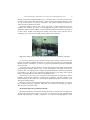
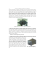
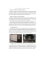
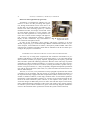
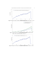
FACTA UNIVERSITATIS Series: Mechanical Engineering Vol. 9, No 1, 2011, pp. 49 - 60 EXPERIMENTAL SETUP FOR EXAMINATION OF AIR CLEANERS FROM SMALL PRODUCTION SOURCES UDC 66.074.5 Miomir Raos, Ljiljana Živković, Nenad Živković, Amelija Đorđević Faculty of Occupational Safety in Niš, University of Niš, Serbia E-mail: [email protected] Abstract. In the laboratory for air quality control at the Faculty of Occupational Safety in Niš, with the purpose of development and scientific activities, an experimental setup for examination of air cleaner from small production sources was designed. The experimental setup has to provide information about parameters of gas mixture and parameters of test air cleaners, necessary for evaluation of operational characteristics and limits of application. Examination of main flow thermal parameters, on an observed filter-ventilation system, was conducted on the experimental line designed for air flow rates up to 2000m3/h. Within the experimental line, the proper equipment for measurement and simulation was designed. This as well as the pollutant presence simulation and the measurement of important parameters was done in real time. The simulation of microclimate air parameters as a carrier gas was done with external air conditioning equipment. Key words: Experimental Setup, Air Canal, Air Cleaner, Data Acquisition EXPERIMENTAL EQUIPMENT CONCEPT The experimental equipment can be described as in its narrow and broad sense, where the experimental equipment in its broader sense implies the system "examination line/air conditioning equipment". This concept can be illustrated as follows [1]: Fig. 1. Experimental setup – block schematic Received May 23, 2010 Acknowledgments. This work has been funded by the Serbian Ministry for Science under the projects No. III-43014. 50 M. RAOS, LJ. ŽIVKOVIĆ, N. ŽIVKOVIĆ, A. ĐORĐEVIĆ A representation of the experimental line is given in Fig. 2. 6 4 2 5 3 1 7 Fig. 2. Experimental line (Solid Works 3D); 1 – primary air ducts; 2 – mechanical impurities cleaner module; 3 – secondary air duct; 4 – gaseous impurities cleaner module; 5 – tertiary air duct; 6 – exhaust into the atmosphere; 7 – centrifugal fan; The experimental equipment in the most narrow sense represents the experimental line itself, which is based on a system of air ducts, a drive unit, and an air conditioning equipment. The experimental equipment in the broader sense, apart from the aforementioned elements, implies appropriate modules which give it a measuring and simulating character. Transport ducts for the gas mixture The basis of transport ducts for the gas mixture are the primary, secondary, and tertiary transport air ducts with a round cross-section of 200mm in diameter. Ducts are made of plastic (PVC) with proper resistance to mechanical and chemical influences. Ducts are connected by an appropriate overlap, 100mm in length, and a corresponding rubber gasket. This type of connection enables proper hydraulic characteristics and minimizes an intake of parasite air through the connecting points. Apart from that, the duct made of plastic have proper smoothness on the inner surface, which minimizes friction and affects the formation of a regular flow structure across and along the duct. The primary transport duct is 1930[mm] in length, placed at the beginning of the experimental line, and its role is to transport air from an enclosed space (room) – carrier gas, to a module for mechanical impurities purification. A significant length of primary duct has to enable the flow stabilization through the experimental line. There are connections for temperature, relative humidity, and velocity transmitters on the primary duct, as well as a connection 6[mm] in diameter for manometer inlet of the differential pressure transmitter. An Fig. 3. The inner surface of primary air duct with important part of the primary duct is the module for transmitters dosing mechanical test impurities into the air flow Experimental Setup for Examination of Air Cleaners from Small Production Sources 51 through a particularly designed solution. Fig. 3 shows the inner view of the primary transport duct (inlet grid for flow stabilization is removed for picture-taking purposes), where we can see the position of velocity, temperature, and relative humidity transmitters, as well as the filter chamber in the back. Secondary transport duct for gas mixture represents a connecting duct between two modules of air purifiers. In essence, it is a straight-line duct with a round cross section of 200[mm], which connects diffusers of the module for mechanical impurities purification to those of the module with adsorption loading. The length of this transport duct is 1020[mm]. Fig. 4 shows the secondary transport duct with connections. Fig. 4. Secondary transport duct with temperature and relative humidity transmitter As we can see from Fig. 4, the secondary transport duct contains connections for temperature and relative humidity transmitter, two connections (6[mm]) for connecting differential pressure transmitters, as well as a system for infiltration of chemical impurities into the air flow. The tertiary part of the gas mixture transport duct leads from the outlet of the module with adsorption loading to the drive unit, i.e. the centrifugal fan. The length of the tertiary transport duct is 2770[mm], and it bridges the altitude difference between experimental line and drive unit. This can be achieved by double diversion of air duct, which ends in elastic connection and axial inlet into the centrifugal fan case. The tertiary air duct has proper connections for transmitters of temperature, relative humidity, and chemical impurities concentrations. In addition, the duct contains a connection 6[mm] on the surface for connecting the differential pressure transmitter of the adsorption loading module. Moreover, this part of the experimental line has a manual regulation flap, as an auxiliary mechanism for flow regulation, which has five positions for defining gas mixture flow from zero to maximum rate. Mechanical impurities purification module Mechanical impurities purification module represents a compact I/O line segment of the experimental line with a square cross section. It consists of a flat part, parallelepipedshaped, with 600[mm] in length, connected to two opposite-oriented diffusers. Total 52 M. RAOS, LJ. ŽIVKOVIĆ, N. ŽIVKOVIĆ, A. ĐORĐEVIĆ length of the module is 1270[mm]. The length is the result of a design solution which allows for flow and spatial characteristics and connects the round cross section of the duct with the square cross section of the module. Sides of modules and diffusers are made of PVC plates by vacuum press technique. The result is proper compactness and strength, as well as smoothness of inner walls of the modules, which is very important because of low hydraulic resistance. Such good flow characteristics of the modules, together with mechanical ones of the PVC, represent a good solution for overcoming vibration in case of gas mixture flows. Connection of the diffuser with the module body was done with a flange, hold screws, and screw nuts with a proper gasket in the flange. Fig. 5 shows the module for mechanical impurities purification. Fig. 5. Module for mechanical impurities purification Panel-type filter elements with proper standard dimensions are housed inside the module for mechanical impurities purification. With proper adjustments it is possible to house panel filter elements with nonstandard dimensions as well as cylindrical filter elements. Filter elements are housed within the flanges of connected elements, after the front diffuser or before the rear diffuser. It is possible to arrange a joint action of the rough and absolute filter (one ahead of the other) in order to determine the efficiency of removing impurities by filter elements. Module for chemical impurities purification Module for chemical impurities purification represents a compact I/O line segment of the experimental line with two opposite-oriented diffusers and a connecting square cross section element. It is made of plastic PVC plates by vacuum press technique, thus attaining proper compactness, strength, and smoothness of inner walls of the module. This is very important because of high mechanical resistance to vibration. Total length of the module is 1270[mm]. Connection of the diffuser with the module body is done with a flange, hold screws, and screw nuts with a proper gasket in the flange. The module for chemical impurities purification houses adsorption cartridges loaded with charcoal. Fig. 6 shows charcoal cartridge pack, manufactured by Eco–engineering company, Fig. 6. Charcoal cartridge pack, ECO Engineering Bor. Experimental Setup for Examination of Air Cleaners from Small Production Sources 53 The basic function of the module for chemical impurities purification is provision of proper housing and position for charcoal cartridges, as well as proper flow characteristics of the gas mixture when passing through the adsorption bed. Drive unit The drive unit represents a set of mechanical, electrical, and electromechanical devices in the experimental line, which have to charge and initiate the base element – gas mixture. Specifically, the drive unit includes a device for forced air circulation – fan, fan drive, electric motor, and frequency regulator for rotation frequency. All elements are parts of the drive unit of the experimental line. If we also include the air condition unit, we can add the cooling system compressor, air heaters, energetic part of the humidifier, as well as drives of the axial fans of the condenser unit and evaporating unit. Fan Flow of the gas mixture through ducts and modules of the purifiers is achieved by force of the centrifugal fan with direct drive. The fan unit is placed at the end of the experimental line and acts as a suction fan. The fan is marked PCRV 2000, as manufactured by a domestic manufacturer Eco-engineering from Bor. The fan is made as a combination of thermo-plastic and steel materials, with PVC, PP, and ABS for all parts coming in contact with aggressive gases. Impeller of the fan is directly connected to the shaft of the electric motor to provide proper and long lasting operation of the device. Suction and delivery duct of the fan is connected by a flexible connection to other parts of the installation in order to reduce vibration. The centrifugal fan is driven by a three-phase asynchronous motor with a squirrel-cage rotor (0.75 kW). In order to regulate velocity of the air, the electric motor is charged by a frequency regulator Siemens, Sinamics G110 [6]. The electric motor synchronic speed, or impeller of the fan, changes with the frequency of the electric current, which affects the gas mixture flow velocity in the ducts. Fig. 7 shows a utilized centrifugal fan and a frequency regulator unit. Fig. 7. Centrifugal fan, Eco-Engineering; frequency regulator unit, SIEMENS G110 54 M. RAOS, LJ. ŽIVKOVIĆ, N. ŽIVKOVIĆ, A. ĐORĐEVIĆ Module for simulation of mechanical impurities Module for simulation of mechanical impurities represents a mechanical assembly made of galvanized plate, placed on the suction duct before the first module for mechanical impurities purification. This module doses mechanical test impurities (standard test dust) with a predefined concentration. Within this module there is a test dust bunker, an anchor with a carrier for fine dosing of the test dust, and a dosing pipe. Module for simulation of chemical impurities Module for simulation of chemical impurities has to meet the requirements for controlled dosing of test chemical impurities. The module contains a reservoir/source of the test chemical compound used as a test impurity (isobutylene [2]), proper measuring and control equipment, as well as elements for infiltration into the air duct. The source/reservoir of the test impurities is a vessel (cylinder) into which the chemical test compound is loaded, and which contains measuring and control equipment. The measuring and control equipment contains a manometer for control of the cylinder exit pressure, a manometer for exit pressure control toward the air duct, and control valves for adapting entry and exit pressure of the vessel to atmospheric pressure. There is also a separator for connecting to a device for gas concentration measurement and gas calibration. Air conditioning device An important factor for efficiency of the purifying process are flow and thermal conditions of the gas mixture in which the filter elements are used during the purifying process. For the simulation of flow and thermal conditions an air conditioning device was used which had to provide given temperature, relative humidity, and flow rate parameters, entitled K.O. D 18V, and manufactured by a domestic manufacturer EI. The device is a split air conditioner with a separate condenser and evaporator, as shown in Fig. 8. Fig. 8. Controller–evaporator and condenser of the air conditioning device The cooling section is compressor-type with the power of 18.6[kW] and R22 coolant. Its cooling capacity ranges from 16.2[kW] (at 22[C]), or 15.5[kW] of sensitive heat, to 18.6[kW] (at 27[C]) of total, or 17[kW] of sensitive heat. The humidifier is steam-type with 4.35[kg/h] steam production and the power of 3.3[kW] with a plastic container. The heating section is a group of three three-phased electric heat pipes, with the capacity of 32 [kW]. Experimental Setup for Examination of Air Cleaners from Small Production Sources 55 Module for data acquisition With the purpose of examining the characteristics of the filter elements and experimental line, a system for measurement and data acquisition was designed. Fig. 9 shows a utilized measurement and data acquisition system. Fig. 9. Acquisition system The measurement system consists of sensors and transmitters of physical and nonelectrical quantities, a device for measurement, a personal computer, and a source of direct current as transmitter power supply. Nine measurement points were realized: M1 – inlet velocity of air flow in the intake air duct, realized by using velocity transmitter type TN 00398935, manufactured by JUMO, GmbH, M2 – temperature and relative humidity in the intake air duct, realized by using transmitter type 90702, manufactured by JUMO, GmbH [3], M3 – differential pressure of the first filter element, realized by using differential pressure transmitter type 4304, manufactured by JUMO, GmbH [4]. Fig. 10 shows the transmitter of velocity, temperature and relative humidity (on the left), and the transmitter of differential pressure (on the right): Fig. 10. Transmitters of velocity, temperature, relative humidity and diff. pressure, JUMO GmbH M4 – temperature and relative humidity of air in the secondary air duct, M5 – concentration of the gaseous chemical test impurities (conditional measurement point), in the secondary air duct, realized by using mobile concentration measuring unit Thermo, model 580S II, M6 – differential pressure of the secondary filter element, M7 – concentration of the gaseous chemical test impurities in the tertiary air duct, M8 – temperature and relative humidity of the air in the outlet duct, M9 – room temperature (enclosed space), realized by using a resistant temperature transmitter with a current output type 90.2523/12, manufactured by JUMO, GmbH. 56 M. RAOS, LJ. ŽIVKOVIĆ, N. ŽIVKOVIĆ, A. ĐORĐEVIĆ Device for data registration (Logoscreen) Transmitters of nonelectrical quantities are connected to a device for data processing and registration, through measurement circuits of the device. After that, data is processed in order of evaluation, combination with other measuring signals by a desired mathematical model, and storage of measured values for each channel separately in a time sequence. The device for data registration is a microprocessor electronic device which contains analogue and digital inputs, electrical communication interfaces, graphical display for data visualization, keys, and interface to Fig. 11. Frontal view of the Logoscreen device user in the form of dropdown menus. In order for the visualization, device settings, and memory expansion to be more flexible, Logoscreen [5] is connected through a RS232 communication interface to a personal computer, with installed PCA software, developed by JUMO GmbH. After measuring has been completed, internally stored data are submitted to the PC for further processing for the purpose of visualization. EXPERIMENTAL VALIDATION OF FILTER - VENTILATION LINE PARAMETERS The usual way of testing filter compartments falls within the determination of performance and efficiency of the filter fills. On the other hand, it is very important that the filter-ventilation assembly be properly adjusted, regarding both the capacity (speed and flow) and other operational and design parameters. Because of the wide range of possible combinations of filter-ventilation assemblies, it is necessary to select the range of experimental research projects in the area of interest (working environment, specific work operations, living environment, etc.). Only an optimally designed and adjusted experimental line with the appropriate filters (filter units) can yield reasonable and useful results suitable for further analysis. The first, or zero tests, were performed on a fully equipped experimental line without a simulation of test pollutants, with the purpose of verifying the designed parameters of the experimental setup equipped with filter compartments (units). The zero tests were performed in standard conditions, which imply standard values of flow-thermal quantities, temperatures, relative humidities, and flows or velocities of gas mixture through the elements of the filter-ventilation system. Likewise, as the response of the system, we observed the changes of differential pressure on filter units and their impact on the aerodynamic and thermodynamic parameters of the system. The results of zero testing of the filter-adsorber system of filter-ventilation are given in the following diagrams (sudden decreases in the measured values represent the moment the system was disconnected): Experimental Setup for Examination of Air Cleaners from Small Production Sources 57 Fig. 12. Volumetric air flow in the filter-ventilation system (m3/h) over time (temp. st.; r.H. st.) Fig. 13. Change of pressure on/below the filter for mechanical impurities (dust) (mbar 100 = Pa), filter F20 (rH st., temp. st.) Fig. 14. Change of air velocity in the channel as a function of time (temp. st., rH st.) 58 M. RAOS, LJ. ŽIVKOVIĆ, N. ŽIVKOVIĆ, A. ĐORĐEVIĆ Fig. 15. Temperature changes over time (temp. st. rH st.) Fig. 16. Change of relative humidity in the filter-ventilation system over time (temp. st. rH st.) Fig. 17. Change of differential pressure of the adsorption filter over time (temp. st., rH st.) Experimental Setup for Examination of Air Cleaners from Small Production Sources 59 CONCLUSION Standard temperature and relative humidity imply the prescribed level of temperature and humidity in the examination of filter units (22 ° C and 50% rH), which have to be provided by the air conditioning system, taking into account the inevitable minimum variation as a result of deviations of real air processing from the desired values. Most figures show a functional dependence of flow and thermal parameters compared to the number of samples of the measuring and acquisition system (function of time). It is important to observe the changes in microclimatic parameters at different places in the system because these changes can be a direct result of the effect of filter materials and individual test pollutants on the state of gas mixture which passes through the filter-ventilation system. Changes in the gas mixture affect the process of purification and efficiency of the filter, the method and quality of the functioning of the whole system, efficiency, etc. The diagrams show the change in temperature, humidity, air velocity in the filter-ventilation system, flow and pressure drops at the very filter compartments, or vacuum behind filter barriers as a result of the position of the fan at the end of the suction pipe. Positions of transmitter temperature, relative humidity, air velocity and differential pressure are predefined and unchangeable up to the end of experimental research. Thus, the legend of each diagram contains the position of the corresponding transmitter (instead of its serial number) in order to facilitate better understanding of the view. Variations of the measured values are within the limits of standard deviations. The occurrence of oscillations of measured parameters is attributed to the inertia of the system and the appearance of turbulence and vortex, especially in cases of increased air velocity, lower humidity, and higher temperatures. Sampling of the acquisition system takes 5 or 10 seconds, with intent to display measured parameters as they are, without approximation, linearization or subsequent processing of the measured values. REFERENCES 1. M. Raos, Investigation of integrated air purifier from low power emission sources, Ph. D. Thesis, University of Niš, Faculty of Occupational Safety, 2008. 2. Isobutylene CAS:115-11-7, Product Identification, Airgas Inc., Randor, PA, USA, 1998. 3. JUMO, Transducers for temperature and humidity, User Manual, Uputstvo 90.1000 – 90.1305, JUMO Wien, Osetereich, M. K. Jucheim GmbH&Co, Fulda, Germany, 2005. 4. JUMO, Pressure and differential pressure transmiters, Typ 4304, B 40.4304, 01-05/00445307, M. K. Jucheim GmbH&Co, Fulda, Germany, 2004. 5. Logoscreen, User manual, B95.5010.0.1, 6.99/00369008, JUMO, M. K. Jucheim GmbH&Co, Fulda, Germany, 2004. 6. Sinamics G110, Operating Instruction (Compact), Siemens, Automation & Drives, Issue 11/04. 60 M. RAOS, LJ. ŽIVKOVIĆ, N. ŽIVKOVIĆ, A. ĐORĐEVIĆ EKSPERIMENTALNA LINIJA ZA ISPITIVANJE PREČISTAČA GASOVA IZ MALIH IZVORA EMISIJE Miomir Raos, Ljiljana Živković, Nenad Živković, Amelija Đorđević U okviru laboratorije za kontrolu kvaliteta vazduha na Fakultetu zaštite na radu u Nišu, a za potrebe razvojnih i naučno istraživačkih aktivnosti, koncipirana je eksperimentalna linija za ispitivanje prečistača gasova iz malih izvora emisije. Eksperimentalna linija treba da pruži informacije o parametrima gasne smeše i parametrima test prečistača gasova, neophodim za ocenu radnih karakteristika i granicama upotrebe. Ispitivanje strujno termičkih parametara od značaja, posmatranog filtro-ventilacionog sistema vršeno je na eksperimentalnoj aparaturi koncipiranoj za protoke gasne smeše do 2000m3/h. U okviru eksperimentalne ispitne linije, formirana je odgovarajuća merno – simulaciona aparatura i postupak simulacije prisustva zagađujućih materija, kao i merenja parametara od značaja vrši se u realnom vremenu. Simulacije mikroklimatskih parametara vazduha kao nosećeg gasa, vrše se eksternim uređajem za kondicioniranje vazduha. Ključne reči: eksperimentalna aparatura, ventilacioni kanal, prečistači gasova, akvizicija podataka