1
K0903 11/02
6160RF
Keypad/Transceiver
Installation and Setup Guide
GENERAL INFORMATION
The 6160RF keypad/transceiver is a combination unit that combines the functions of the following devices:
• 6160 Alphanumeric Addressable Keypad
• 5881H RF Receiver
• 5800TM Transmitter Module
The 6160RF Keypad/Transceiver may be used on any control panel that supports 5800 Series wireless devices
(e.g., VISTA 10P, VISTA-15P, VISTA-20P).
FEATURES
• Supports wireless key transmitters (e.g.; 5804) and bi-directional transmitters (e.g.; 5804BD. 5827BD).
• Supports wireless keys with high-security (encryption) capability (e.g.; 5804E).
• Provides a nominal range of 200' for the RF transmitters (some transmitters have a shorter range).
• Supports RF jam detection when the receiver is enabled.
• Capable of sending status signals (Armed, Ready, etc.) to bi-directional units such as 5804BD, 5804BDV and
5827BD.
UL
The following transmitters are not intended for use in UL installations: 5804, 5804BD, 5804BDV, 5804E and 5827BD.
INSTALLING THE 6160RF
Locate the 6160RF in an area and at a height where
it is convenient for user operation. The 6160RF must
be at least 10 ft from the control panel to ensure
proper operation of the RF receiver.
Mounting And Wiring
The 6160RF has terminal blocks for connection to
power and data wires. Removing the keypad’s case
back provides access to the terminal blocks.
The 6160RF can be surface mounted directly to
walls, or to a single- or double-gang electrical box.
Follow these steps to mount and wire the keypad:
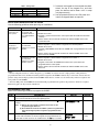
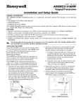
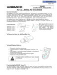
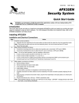
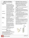
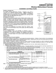
1. Detach the case back by pushing up into one of
the two slots at the bottom of the keypad with the
blade of a small screwdriver (this will push in the
release snap), then pull that side of the case back
away. Repeat for the other side. Refer to Figure 1
for location of the case back release snaps.
2. Pass the wiring from the control panel through
the opening in the case back. (see the control
panel’s instructions for proper run lengths.)
a. If surface wiring is being used, wiring may be
routed through the top or the bottom left-side
breakout in the case back. The breakouts must
be punched out using a screwdriver before
mounting the case back.
b. If desired, wires may be strain-relieved to the
wire tie point on the inside of the case back
with a tie wrap (not supplied).
3. Mount the case back to a wall or to an electrical
box using the 25mm-long self-tapping screws
supplied (mollies for drywall are not supplied).
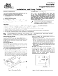
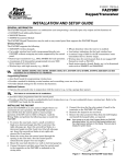
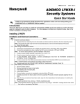
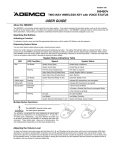
4. Connect the power and data wires from the
control panel to the terminals on the 6160RF as
indicated in Figure 2 and Table 1.
ARMED
READY
Y +
G
+
+
+
+
WIRING TERMINALS
(TO CONTROL PANEL)
Figure 1. Removing the Case Back
Figure 2 - 6160RF Wiring Details
6160RF-002-V1
MOUNTING
RELEASE
SNAPS
6164RF-003-V0
NOTE:
TO REMOVE REAR COVER
PUSH IN THE TWO MOUNTING
SNAPS LOCATED ALONG THE
BOTTOM OF THE KEYPAD
AND LIFT COVER UP.
Table 1 - Wiring Table
Keypad
▲ G (Data Out)
+
Y (Data In)
y
Control Panel
Data In
-Aux Pwr (GND)
+Aux Pwr
Data Out
5. Re-attach the keypad to the mounted case back.
Attach the top of the keypad first, and then
press the bottom section down until it snaps
into place securely.
Wire Color
Green
Black
Red
Yellow
6. Peel off protective film on the LED panel and
install the keypad labels as required.
APPLICATION GUIDELINES FOR THE 6160RF
Use the following guidelines when planning an installation:
If…
This is the only
transceiver on
the system,
And…
You want to use both
the receiver and
transmitter function
on a single-partition
system,
Then…
• Set the keypad to a device address assigned to the desired partition.*
• Enable the receiver.
• Program a system House ID in the control panel (this will enable the transmitter
function).**
• Set the wireless devices that will communicate with this 6160RF to the same
system House ID.
There is another
receiver or
transceiver on
the system,
You want to use only
the transmitter
function on a second
partition,
• Set the keypad to a device address assigned to the desired partition.*
• Disable the receiver.
• Program a DIFFERENT House ID in the 6160RF than is programmed in the control
panel.*/ **
• Set the wireless devices that will communicate with this 6160RF to the same
House ID as the 6160RF.
You want to use only
the transmitter
function on a singlepartition system,
• Set the keypad to a device address assigned to the Partition 1.
• Disable the receiver.
• Program a House ID in the 6160RF that matches the system House ID
programmed in the control panel.*
• Set the wireless devices that will communicate with this 6160RF to the same
House ID.
Notes:
* On Vista-40 panels and above, wireless keypads (e.g., 5827BD) can only be used on a single partition. This partition is
programmed in field 1*48, and must match the partition assigned to the 6160RF. Wireless keys can be used on more than one
partition, using a House ID programmed in the 6160RF and the devices. In this case, the wireless keys must be assigned to the
same partition as the 6160RF.
** On Vista-20P panels, the 6160RF will use the House ID programmed in the panel for the partition to which it is assigned.
Wireless keypads can only be used on Partition 1.
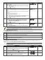
PROGRAMMING THE 6160RF
Refer to the following procedure to program the 6160RF:
STEP
1.
DESCRIPTION
Enter the program mode by pressing the [1] and [3] keys simultaneously for
a few seconds within 60 seconds after applying power.
2.
(Keypad Address) Enter the two-digit keypad address. Press the [✳] key to
continue.
DISPLAY
CHOICES
'32%((6)77= <<
00-31
6)')-:)6
32?= 3**A
1= ON
0 = OFF
Notes: (1) Refer to the control panel’s installation instructions for the
acceptable keypad addresses.
(2) On the VISTA-40 and above the 6160RF’s partition assignment must
match the RF keypad partition assignment programmed in field
(1*48).
3.
(Receiver Enable) Enter [1] to enable, or [0] to disable Receiver. Enable the
receiver if RF transmitters or wireless keypads are programmed into the
control and no other receivers are enabled. Press the [✳] key to continue.
2
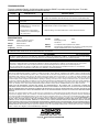
STEP
4.
DESCRIPTION
(Receiver Address) If receiver is enabled, enter the two-digit receiver
address. (01-30).
Note:
DISPLAY
CHOICES
6)'%((6)77= <<
00-30
,397)-(= <<
00-31
,-+,7)'96-8=
3**?= 32A
1= Enable
0 = Disable
(-7%&0),7():#
23?= =)7A
1= YES
0 = NO
Refer to the control panel’s installation instructions for the acceptable
receiver addresses.
Press the [✳] key to continue.
5.
(House ID) This prompt will only appear if the receiver is disabled. If the
receiver is enabled the 6160RF will use the House ID programmed in the
panel.
Refer to the Application Guidelines on the previous page when selecting a
House ID.
To program a House ID: Enter 01-31.
To disable the transmitter: Enter 00
Note: All devices that you want to receive status from the 6160RF must be set
to the same House ID as the 6160RF (refer to Table on Page 1).
Press the [✳] key to continue.
6.
(Enable High Security Mode) Enter [1] to select High Security Mode.
Note: If this mode is enabled, the 6160RF will only recognize encrypted
devices. If this mode is disabled, the 6160RF will recognize both
encrypted and non-encrypted devices. *
Press the [✳] key to continue.
7.
(Disable High Security Devices) Press the [✳] key to skip this prompt and
exit Program Mode.
Note: If you need to disable encrypted devices, refer to the Disabling High
Security Devices section.
* When operating the system in High-Security mode, 5804BD wireless keys will still function. If you want the system to
recognize only encrypted wireless devices, program only encrypted devices in the system.
ACTIVATING HIGH SECURITY DEVICES
This following procedure should be followed if using High-Security (encrypted) devices.
STEP
DESCRIPTION
1.
Follow the normal procedure for programming the device into the control panel (refer to the Installation Instructions for
the device that you are programming). Exit out of Programming Mode.
2.
Put the control panel in Go/ No Go Test mode. (See the Installation Guide for the panel being installed.)
3.
Follow the instructions supplied with each wireless device to enroll the device in High-security mode. The 6160RF will
momentarily display the serial number of the device.
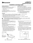
DISABLING HIGH SECURITY DEVICES
This mode gives you the ability to disable high security on all wireless keys that have been enrolled in the
6160RF. This is particularly useful if a user loses a wireless key.
!
STEP
1.
2.
3.
Once high-security (encrypted) devices have been disabled, they will only operate if the 6160RF is set to listen to both
encrypted and non-encrypted devices (programming step 6, above). To completely disable the devices, they must be deleted
from the control panel.
DESCRIPTION
After the keypad has been powered for at least 60 seconds hold down
the [1] and [3] keys at the same time for 3 seconds. The current keypad
address will be displayed. (You cannot change the keypad’s address at
this point.) Press the [✳] key to continue.
(Delete High Security Devices) Press the [1] key to remove all highsecurity (encrypted) devices. Press the [✳] key to continue.
If YES was selected in Step 2 the unit will display a confirm request to
delete the stored high security device. Press the [1] key to accept,
followed by the [✳] key to exit the programming mode.
3
DISPLAY
CHOICES
'32%((6)77= <<
00-31
(-7%&0),7():#
23?==)7A
%6)=39796)#
23?==)7A
1= YES
0 = NO
1= YES
0 = NO
TROUBLESHOOTING
The error messages listed in the following table cause the 6160RF to produce a single ding tone. The table
describes the error messages and the corrective actions.
Display
Probable Cause
Corrective Action
Lb
Low battery in the wireless key
1. Replace the battery if the wireless key has a replaceable battery.
Open Ckt
No data is being received from the
control panel.
Verify that the keypad DI (yellow) wire is connected properly.
Check 09
1. The control panel does not see the
6160RF Receiver, or the Receiver
is not functioning.
1a. Verify that the keypad DI (yellow) and DO (green) wires are connected properly.
2. Another device on the keypad
terminals is not communicating to
the control panel.
2. Verify the wiring connections between the control and all other devices.
2. Replace the transmitter if the wireless key does not have a replaceable battery.
1b. Verify that the control’s receiver address is correct.
SPECIFICATIONS
Physical:
5-3/8” H x 7-3/8” W x 1-1/4” D
(137mm x 187mm x 32mm)
Wiring:
Refer to Table 1
Range:
200 ft (60.9 m) nominal
Frequency:
345 MHz
Current:
Standby
Backlighting on and
Sounder on
50mA
Display:
2 x 16 alphanumeric supertwist LCD, backlit
Sounder:
Tone Generator Integrated Circuit. (fire alarm is loud pulsing tone;
burglary/audible panic alarm is continuous tone)
150mA
FOR DETAILS ON THE LIMITATIONS OF THE ENTIRE ALARM SYSTEM, REFER TO THE INSTALLATION INSTRUCTIONS FOR THE
CONTROL PANEL BEING INSTALLED IN CONJUCTION WITH THIS DEVICE.
FCC ID CFS8DL6160RF
FCC STATEMENT
This device complies with Part 15 of the FCC rules. Operation is subject to the following two conditions: (1) This device may not cause harmful
interference, and (2) This device must accept any interference received, including interference that may cause undesired operation.
FEDERAL COMMUNICATIONS COMMISSION (FCC) Part 15 STATEMENT
This device complies with part 15 of the FCC rules. Operation is subject to the following two conditions: (1) This device may not cause harmful
interference, and (2) this device must accept any interference received, including interference that may cause undesired operation.
The user shall not make any changes or modifications to the equipment unless authorized by the Installation Instructions or User's Manual.
Unauthorized changes or modifications could void the user's authority to operate the equipment.
ADEMCO LIMITED WARRANTY
Alarm Device Manufacturing Company, a Division of Pittway Corporation, and its divisions, subsidiaries and affiliates ("Seller"), 165 Eileen Way,
Syosset, New York 11791, warrants its products to be in conformance with its own plans and specifications and to be free from defects in materials and
workmanship under normal use and service for 24 months from the date stamp control on the product or, for products not having an Ademco date
stamp, for 12 months from date of original purchase unless the installation instructions or catalog sets forth a shorter period, in which case the shorter
period shall apply. Seller's obligation shall be limited to repairing or replacing, at its option, free of charge for materials or labor, any product which is
proved not in compliance with Seller's specifications or proves defective in materials or workmanship under normal use and service. Seller shall have no
obligation under this Limited Warranty or otherwise if the product is altered or improperly repaired or serviced by anyone other than Ademco factory
service. For warranty service, return product transportation prepaid, to Ademco Factory Service, 170 Michael Drive, Syosset, New York 11791.
THERE ARE NO WARRANTIES, EXPRESS OR IMPLIED, OF MERCHANTABILITY, OR FITNESS FOR A PARTICULAR PURPOSE OR
OTHERWISE, WHICH EXTEND BEYOND THE DESCRIPTION ON THE FACE HEREOF. IN NO CASE SHALL SELLER BE LIABLE TO ANYONE
FOR ANY CONSEQUENTIAL OR INCIDENTAL DAMAGES FOR BREACH OF THIS OR ANY OTHER WARRANTY, EXPRESS OR IMPLIED, OR
UPON ANY OTHER BASIS OF LIABILITY WHATSOEVER, EVEN IF THE LOSS OR DAMAGE IS CAUSED BY THE SELLER'S OWN NEGLIGENCE
OR FAULT.
Seller does not represent that the products it sells may not be compromised or circumvented; that the products will prevent any personal injury or
property loss by burglary, robbery, fire or otherwise; or that the products will in all cases provide adequate warning or protection. Customer understands
that a properly installed and maintained alarm may only reduce the risk of a burglary, robbery, fire or other events occurring without providing an alarm,
but it is not insurance or a guarantee that such will not occur or that there will be no personal injury or property loss as a result. CONSEQUENTLY,
SELLER SHALL HAVE NO LIABILITY FOR ANY PERSONAL INJURY, PROPERTY DAMAGE OR OTHER LOSS BASED ON A CLAIM THE
PRODUCT FAILED TO GIVE WARNING. HOWEVER, IF SELLER IS HELD LIABLE, WHETHER DIRECTLY OR INDIRECTLY, FOR ANY LOSS OR
DAMAGE ARISING UNDER THIS LIMITED WARRANTY OR OTHERWISE, REGARDLESS OF CAUSE OR ORIGIN, SELLER'S MAXIMUM LIABILITY
SHALL NOT IN ANY CASE EXCEED THE PURCHASE PRICE OF THE PRODUCT, WHICH SHALL BE THE COMPLETE AND EXCLUSIVE REMEDY
AGAINST SELLER. This warranty replaces any previous warranties and is the only warranty made by Seller on this product. No increase or alteration,
written or verbal, of the obligations of this Limited Warranty is authorized.
i.¢l
K0903 11/02
165 Eileen Way, Syosset, NY 11791
Copyright 2002 PITTWAY CORPORATION