1
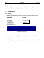
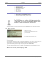
User's manual
Pressurized
enclosure system
F870S
Manual_F870S_v1.0.0_2011.doc
F870S
Inhalt
Page 2
Content
1
2
Operation instruction for Explosion protected device............................................................................ 4
Introduction: Pressurized enclosure system F870S.............................................................................. 5
2.1
Explosion protection: pressurized enclosure ................................................................................. 5
2.2
Pressurized enclosure according to EN 60079.............................................................................. 5
2.3
Pressurized enclosure system F870S ........................................................................................... 6
2.3.1
Simultaneous PID- control of cabinet pressure and flow rate ................................................ 6
2.3.2
Enlarged, free programmable range of operation................................................................... 7
2.3.3
Lowered cabinet stressing due to smaller pressure and pressure gradients ......................... 8
2.4
Components of pressurized enclosure system F870S .................................................................. 8
2.4.4
Leakage compensation........................................................................................................... 9
2.4.5
Continuous flow .................................................................................................................... 10
2.4.6
F870S - Application using „Containment Systems “ ............................................................. 10
2.5
Peripherals ................................................................................................................................... 11
2.5.1
Ex i- external sensory: ES872 .............................................................................................. 11
2.5.2
Configuration module: CM873 .............................................................................................. 11
2.5.3
Operating panels .................................................................................................................. 11
2.5.4
Common operating panels: BT 854.1 and BT 855.1 ............................................................ 11
2.5.5
Intelligent operating panel type BT871 ................................................................................. 11
2.5.6
Disconnector unit SR852 and power relay SR853 ............................................................... 11
2.6
Features in operation zone 21 (Dust) .......................................................................................... 12
2.6.1
Purging period -> cleaning period: cleaning the housing inside ........................................... 12
2.6.2
Additional marking ................................................................................................................ 12
2.7
Additional information: EC- type certificate F850-SYST .............................................................. 12
2.8
Conformity with standards ........................................................................................................... 12
3 Installation and Connection ................................................................................................................. 13
3.1
Mounting ...................................................................................................................................... 13
3.1.3
Control unit FS870S ............................................................................................................. 13
3.1.4
Particle barrier....................................................................................................................... 13
3.1.5
Proportional solenoid valve................................................................................................... 13
3.1.6
Operator panels BT8xx.x ...................................................................................................... 13
3.1.7
Disconnector unit SR852 and power relay SR853 ............................................................... 14
3.2
Connecting and Commissioning .................................................................................................. 14
3.2.1
Connection hints ................................................................................................................... 15
3.2.2
Switching power off ability .................................................................................................... 15
3.2.3
Intrinsically safe (Ex i-) connection of FS870S ..................................................................... 16
3.2.4
Connections FS870S of protection class (Ex e) ................................................................... 16
3.2.5
Default parameter ................................................................................................................. 17
3.2.6
Ex works parameter – Reset ................................................................................................ 18
3.3
Maintenance................................................................................................................................. 18
3.4
Repairs......................................................................................................................................... 18
4 Operation............................................................................................................................................. 19
4.1
Human interface........................................................................................................................... 19
4.1.1
Display .................................................................................................................................. 19
4.1.2
Joystick ................................................................................................................................. 19
4.1.3
Log file (show Log) ............................................................................................................... 19
4.1.4
How to enter and leave the bypass mode ............................................................................ 20
4.2
Parameter input and parameter query ......................................................................................... 21
4.2.1
Operation menu .................................................................................................................... 21
4.2.2
Parameter input menu .......................................................................................................... 21
4.2.3
Menu exposition.................................................................................................................... 22
4.3
Alarm and malfunction indications ............................................................................................... 23
4.3.4
Alert....................................................................................................................................... 23
4.3.5
Error messages..................................................................................................................... 23
5 Annex .................................................................................................................................................. 24
5.1
Technical Details.......................................................................................................................... 24
5.1.6
Pneumatic data ..................................................................................................................... 24
5.2
Type codes................................................................................................................................... 25
5.3
Marking ........................................................................................................................................ 26
Gönnheimer Elektronic GmbH
Tel.: +49 (6321) 49919-0
Fax: +49 (6321) 49919-41
F870S
5.4
5.5
5.6
5.7
5.8
5.9
5.10
Inhalt
Page 3
Dimensions .................................................................................................................................. 27
Mounting examples ...................................................................................................................... 29
Flow diagram................................................................................................................................ 29
Block diagram .............................................................................................................................. 30
Transport, Storing, Disposal and Repairs .................................................................................... 31
Sequence of operation diagram................................................................................................... 32
List of Parameters .................................................................................................................... 33
The symbols WARNING, CAUTION, NOTE
This symbol warns of a serious hazard. Failure to observe this warning may
result in death or the destruction of property.
This symbol warns of a possible failure. Failure to observe this caution may
result in the total failure of the device or the system or plant to which it is
connected.
This symbol highlights important information.
Safety Measures: to read and to comply
Warning! Extreme caution is advised when handling this device. High
electrical discharge is possible and can be fatal.
Work on electrical installations and apparatus in operation is generally forbidden in
hazardous locations, with the exception of intrinsically safe circuits. In special cases
work can be done on non-intrinsically safe circuits, on the condition that during the
duration of such work no explosive atmosphere exists.
Only explosion protected certified measuring instruments may be used to ensure
that the apparatus is voltage-free. Grounding and short-circuiting may only be carried out, if there is no explosion hazard at the grounding or short circuit connection.
Danger of static charge!
Clean only with humid cloth!
Do not open when an explosive dust atmosphere is present!
Gönnheimer Elektronic GmbH
Tel.: +49 (6321) 49919-0
Fax: +49 (6321) 49919-41
F870S
1
1 Operation instruction for explosion protected device
Page 4
Operation instruction for Explosion protected device
Application and Standards
This instruction manual applies to explosion-protected devices of types below. This apparatus is
only to be used as defined and meets requirements of EN 60 079 particularly EN60 079-14
"electrical apparatus for potentiality explosive atmospheres".
Use this manual in hazardous locations, which are hazardous due to gases and vapors according to the explosion group and temperature class as stipulated on the type label. When installing
and operating the explosion protected distribution and control panels you should observe the
respective nationally valid regulations and requirements.
General Instructions
Work on electrical installations and apparatus in operation is generally forbidden in hazardous
locations, with the exception of intrinsically safe circuits. In special cases work can be done on
non-intrinsically safe circuits, on the condition that during the duration of such work no explosive
atmosphere exists.
Only explosion protected certified measuring instruments may be used to ensure that the apparatus is voltage-free. Grounding and short-circuiting may only be carried out, if there is no explosion hazard at the grounding or short circuit connection.
To achieve an impeccable and safety device operation, please take care for adept transportation, storage and mounting, as well as accurate service and maintenance. Operation of this device should only be implemented by authorized persons and in strict accordance with local
safety standards.
The electrical data on the type label and if applicable, the "special conditions" of the test certificate BVS 10 ATEX E 112are to be observed.
For outdoor installation it is recommended to protect the explosion protected distribution and
control panel against direct climatic influence, e.g. with a protective roof. The maximum ambient
temperature is 40°C, if not stipulated otherwise.
Terminal compartment in Increased Safety
When closing, it is to be ensured that the gaskets of the terminal compartment remain effective,
thus maintaining degree of protection IP 54 according to EN 60529. Close unused entries by
impact-proof stopping plugs, which are secured against self-loosening and turning.
Do not open the device in Ex area, as long the device is energized.
Inside area with explosive dust do clean the inner of the housing of the dust before closing the
housing.
Maintenance Work
The gaskets of Ex e enclosures are to be checked for damages and replaced, if required. Terminals, especially in the Ex e chamber are to be tightened. Possible changes in color point to
increased temperature. Cable glands, stopping plugs and flanges are to be tested for tightness
and secure fitting.
Intrinsically Safe Circuits
Erection instructions in the testing certificates of intrinsically safe apparatus are to be observed.
The electrical safety values stipulated on the type label must not be exceeded in the intrinsically
safe circuit. When interconnecting intrinsically safe circuits it is to be tested, whether a voltage
and/or current addition occurs. The intrinsic safety of interconnected circuits is to be ensured.
(EN 60079-14, section 12)
Gönnheimer Elektronic GmbH
Tel.: +49 (6321) 49919-0
Fax: +49 (6321) 49919-41
F870S
2 Pressurized enclosure system F870S
Page 5
2 Introduction: Pressurized enclosure system F870S
2.1
Explosion protection: pressurized enclosure
The use of pressurized enclosures allows the operation of ‘non explosion protected’ devices
in hazardous areas inside zone 1 and zone 2. The protection type ‘pressurization’ is based
on the principle of maintaining a constant pressure using air or a protective gas to prevent
an explosive mixture forming near the device inside the pressurized enclosure.
Before start-up, the pressurized enclosure must be purged with air or protective gas to remove any explosive mixture that may be inside the enclosure.
2.2
Pressurized enclosure according to EN 60079
Since the second issue of the standard EN 50016 (May, 1996) control devices for the protection type "pressurized enclosure" are classified as security related devices.
At that time, the notified bodies, (PTB, EXAM, TUEV NORD, etc.) declared that an ex pcontrol device must fulfill the category 3 of EN 954-1. This concept was taken over also in
the standards EN 60079 ff.
After the replacement of EN 954-1 by the standards IEC / EN 61508-1 and -2, respectively
EN ISO DIN 13849-1 and -2 and DIN EN 50495 a security level of at least SIL 2 is required
for a pressurized enclosure control unit according to EN 60079-2. This is a valid arrangement between the German notified bodies.
Figure 1: Performance levels
The pressurized enclosure system F870S reaches performance level „d“ according to
EN 13849 and therefore it reaches SIL Level 2 according to IEC / EN 61508.
Gönnheimer Elektronic GmbH
Tel.: +49 (6321) 49919-0
Fax: +49 (6321) 49919-41
F870S
2.3
2 Pressurized enclosure system F870S
Page 6
Pressurized enclosure system F870S
2.3.1 Simultaneous PID- control of cabinet pressure and flow rate
Based on the first introduction of proportional valve technology within pressurized enclosure
systems (patented system Gönnheimer F850) an additional active proportional valve was
integrated to the F870S in the outlet.
Figure 2: block diagram simultaneous pressure and flow control
This concept permits simultaneous PID-regulation of cabinet pressure and flow rate and
generates new solutions and possibilities for pressurized enclosure systems and attachments.
Gönnheimer Elektronic GmbH
Tel.: +49 (6321) 49919-0
Fax: +49 (6321) 49919-41
F870S
2 Pressurized enclosure system F870S
Page 7
2.3.2 Enlarged, free programmable range of operation
In comparison to common Ex p control systems, the FS870S offers an increased and free
programmable range of operation (characteristic pressure / flow curve).
The conventional systems are characterized by a fixed pressure / flow curve (see e.g.
FS850S) with an offset, caused by the opening pressure of the passive mechanical outlet
valve. This typical opening pressure (2... 4 mbar at standard systems) is required to minimize the system leakage rate during normal operation.
Fixed curves by control
devices with flow measurement with plate orifice
Figure 3: Range of operation
The input and output sided PID-control loops allow the FS870S to perform in the whole
range of operation (see figure 2).
Gönnheimer Elektronic GmbH
Tel.: +49 (6321) 49919-0
Fax: +49 (6321) 49919-41
F870S
2 Pressurized enclosure system F870S
Page 8
2.3.3 Lowered cabinet stressing due to smaller pressure and pressure gradients
During the purging phase a high flow rate should be achieved to shorten the purge time.
Based on their construction, conventional Ex p- systems show only a smooth rising of the
flow rate while increasing the cabinet pressure.
In this aspect, the FS870S with its reduced flow restriction and back pressure is superior to
any conventional Ex p system.
Within midrange flow rates, the load to the Ex p- cabinet walls is up to four times lower in
comparison to conventional systems!
2.4
Components of pressurized enclosure system F870S
The pressurized enclosure system F870S contains at least the control unit FS870S and a
solenoid valve. Each can be mounted in- or outside the enclosure. Furthermore several remote controls (operation panels) are available to improve ease of operation. It is also possible to connect intrinsically safe sensors to the control unit FS870S.
The pressurized enclosure system F870S has two basic operation modes:
•
Pressurization using leakage compensation
•
Pressurization using continuous flow of protective gas.
Gönnheimer Elektronic GmbH
Tel.: +49 (6321) 49919-0
Fax: +49 (6321) 49919-41
F870S
2 Pressurized enclosure system F870S
Page 9
2.4.4 Leakage compensation
Within this operation mode the unit generate and hold a pressure level of at lest 0.8 mbar
(80 Pa) inside the Ex p- cabinet.
The use of a proportional solenoid valve prevents wasting of the purge medium while the
pre purging procedure as well later in basic operation mode.
In tradition to the control unit GÖNNHEIMER FS850S, the first Ex p- control unit using proportionally working pressure and flow control, the FS870S works as well as an input-sided
pressure regulator:
The proportional solenoid valve is the actuator of a PID- control and regulates the incoming
purge medium accordingly to the leakage of the cabinet. The benefits of pressure feedback
control are:
1. Considerable less consumption of protective gas - additional costs for proportional valve will
be amortized soon
2. Increased service reliability achieved by constant pressure inside enclosure - increasing leakage caused by e.g. ageing of the enclosure will be balanced and sudden failure is pre vented
3. Almost no flow noise and only a small protective gas consumption using a solid enclosure
Figure 4: Consumption of protective gas
Another advantage using a proportional solenoid valve is; that pressure control is also used
during purging. A set-point pressure will be achieved in the enclosure, while the flow volume, that leaves the enclosure, will be recorded and integrated over time, until the required
purge volume is achieved. The advantages are:
1. A defined pressure while purging - pressure sensitive parts of the enclosure, like membrane switch panels or windows, will not be overloaded.
2. Purge volume accuracy is achieved by integration of the purge medium flow volume at
the outlet. Wasting purge medium is no more a topic of today.
The use of the F870S system leads to a considerable stress relief of the Ex p cabinet and
sensitive parts like foil keyboards, windows etc.. In comparison to conventional Ex p- systems, the FS870S requires a much lower cabinet pressure to achieve a comparable flow
rate. (Example: A reduction of the cabinet pressure by 5 mbar leads to 50 kg / m² decreased load at the cabinet walls).
Gönnheimer Elektronic GmbH
Tel.: +49 (6321) 49919-0
Fax: +49 (6321) 49919-41
F870S
2 Pressurized enclosure system F870S
Page 10
2.4.5 Continuous flow
The control unit FS 850S incorporates the operation mode „continuous flow“. This operation
mode is necessary, for example if an analyzer produces an explosive atmosphere inside
the enclosure (containment system). The operation mode continuous flow flushes the enclosure permanently. After the (pre-) purging procedure (purging process) a set-point flow
rate is adjusted during normal operation. A flow rate minimum will be monitored also.
This system design allows a simultaneous PID- control of cabinet pressure and flow rate
and opens new possibilities within the construction of pressurized enclosure systems and
applications.
In operation mode "continuous flow" the FS870S is capable to lower the flow rate from a
high value during purging to a low value during normal operation at a constant, low cabinet
pressure level. (Example: 3 liters/sec. to 0.3 liters/sec. decrease without pressure variation)
Figure 5: time diagram
2.4.6 F870S - Application using „Containment Systems “
„Containment Systems“ are defined as parts of a device within a pressurized enclosure,
which could emit combustible gas (or occasionally an explosive environment: zone 1, explosive mixture) from within the enclosure.
In order to receive an Ex p-System including a „Containment System“, which is failsafe according EN 60079-2, with the attribute 'no emission', the following conditions must be met:
1.
The flammable substance inside the containment system is in the gas or vapor phase
when operating between the specified temperature limits
2.
The minimum pressure specified for pressurized enclosure is at least 50 Pa higher than
the maximum pressure specified for the containment system
3.
An automatic safety device initiates, if the pressure difference falls below 50 Pa.
This automatic safety device can be activated by a difference pressure switch, looped into
the external alarm loop (terminal 5/6 on FS870S). If an alarm occurs on this loop, the control device FS870S will turn off the ignition-capable device immediately. After alarm canceling the control device FS870S starts operation automatically with the purging procedure.
The external alarm loop is made by a normaly closed connection method.
Gönnheimer Elektronic GmbH
Tel.: +49 (6321) 49919-0
Fax: +49 (6321) 49919-41
F870S
2.5
2 Pressurized enclosure system F870S
Page 11
Peripherals
2.5.1 Ex i- external sensory: ES872
The intrinsically safe bus interface is used to transmit measurement values from the external proportional sensor module ES872 to the control unit. This allows the integration of additional safety control features into the purge control system.
This interface is also suitable for e.g. temperature or other sensors.
2.5.2 Configuration module: CM873
Using the same Ex i- bus, the customer can connect the optional configuration module
CM873 to load application specific configuration data and parameters into the control unit
without further manual programming.
The handling is quite simple: plug this CM873 into the intended port and restart the control
device.
2.5.3 Operating panels
For the control unit FS870S several operating and visualizing panels are available. These
panels consist of the explosion protection class 'intrinsically safe' and are considerably advantageous, particularly when the control unit is mounted inside the enclosure.
2.5.4
Common operating panels: BT 854.1 and BT 855.1
• On/Off-Switch
• Key-operated switch for bypass
• LED-indicator for READY and ON
The connection to the control unit consists of 6 wires.
2.5.5 Intelligent operating panel type BT871
This operation panel indicates operation and malfunction reports as plain text. The 5 membrane switches offer total command of the control unit. Status, actual pressure, flow rate as
well as remaining purge time are always available.
The connection to the control unit consists of only 4 wires.
Signal lamps on BT871
The BT871 has three colored signal lights (LED). These report system states and warnings.
2.5.6 Disconnector unit SR852 and power relay SR853
According to EN 60079-2 all non- intrinsically safe connections of the ignition capable apparatus must be disconnect, if the protection gas pressure falls below the safety limit. In many
applications more than the two connector terminals on the control unit FS870S are needed.
In these cases the disconnector unit SR852, with 8 respectively 16 galvanically separated
connectors, is considerable helpful.
The power relay S853 provides 4 lines with switching power of 250V, 16 A.
Gönnheimer Elektronic GmbH
Tel.: +49 (6321) 49919-0
Fax: +49 (6321) 49919-41
F870S
2.6
2 Pressurized enclosure system F870S
Page 12
Features in operation zone 21 (Dust)
2.6.1 Purging period -> cleaning period: cleaning the housing inside
In zone 21 the housing must not be purged in comparison to the operation in gas zone 1.
The operator has to insert the purging volume zero “0 [l]” into the parameter menu.
Purging in the presence of combustible dust would generate a dangerous explosive atmosphere inside the cabinet.
In the zone 21 the purging period is replaced by a cleaning period, viz. the operator has to
remove thoroughly the combustible dust inside before he is energizing the electrical parts
inside the cabinet.
After cleaning the pressure inside of the cabinet prevent an infiltration of dust.
2.6.2 Additional marking
The cabinet must contain a well viewable sign with the following content:
„WARNING: REMOVE ALL DUST FROM THE INSIDE OF THE ENCLOSURE BEFORE
CONNECTING OR RESTORING THE ELECTRICAL SUPPLY“
On Ex p cabinets suitable for zone 21, which can be opened without tools, has to be placed
the following mark:
„WARNING: DO NOT OPEN WHILE ENERGIZED UNLESS IT IS OBVIOUS THAT NO
COMBUSTIBLE DUST IS PRESENT“
2.7
Additional information: EC- type certificate F850-SYST
Gönnheimer features as manufacturer of Ex p- Systems a comprehensive ATEX Ex pSYSTEM Certification of a notified body.
Provides a economical solution for small quantities
•
•
•
•
•
certified for Ex- Zone 1
enhanced for Dust- Ex, Zone 21 (category 2D)
the first ATEX certification of this type in Europe
matches > 80% of all individual customer systems
enhanced pressure ranges: 27mbar, 350mbar and 1 bar.
Costumer advantages:
+ usual delivery time, + usual quality,+ usual costs,+ no additional efforts
2.8
Conformity with standards
The explosion proof control unit FS870S meets requirements of listed standards in the attachment (Declaration of conformity). They were developed, manufactured and tested in
accordance with state-of-the-art engineering practice and ISO9001:2008.
Gönnheimer Elektronic GmbH
Tel.: +49 (6321) 49919-0
Fax: +49 (6321) 49919-41
F870S
3 Mounting and connection
Page 13
3 Installation and Connection
3.1
Mounting
3.1.3 Control unit FS870S
The control unit can be placed inside a hazardous area. The location (inside or outside the
enclosure) as well as the position is almost arbitrary.
The control unit has 4 holes on the rear plate for mounting, although fixing only with the
screw connection of intake or outlet is sufficient.
While mounting observe local safety guidelines and
the regulative DIN EN 60079-14.
The reference input of the device (M5 thread on the
left side) should be in the ex area.
If the device is mounted inside the Ex p- housing, the reference input
must be connect to the ambient by a pipe connection.
The solenoid valve(s) and the control unit (respectively pressure monitor) should be mounted on the
enclosure as far away from each other as possible
(E.g. space diagonal arrangement), to achieve a total
purging.
3.1.4 Particle barrier
The control device contains a particle barrier according to EN 60079-2. Therefore it is allowed to exhaust the purge medium direct onto the ex area.
3.1.5 Proportional solenoid valve
The proportional working solenoid valve (SVP…) should be mounted outside of the Ex p
cabinet. The mounting direction is arbitrary.
3.1.6
Operator panels BT8xx.x
° Operator panel BT871.0
The operating tableau BT871.0 (without rear) becomes directly mounted outside on the Ex
p- cabinet. Therefore 5 drillings must be made into the cabinet. Please refer the drilling
scheme in the appendix.
° Operator panel BT871.5
The operator panel BT871.5 contents a complete housing in protection class IP65. It could
be mounted arbitrary in hazardous area Zone 1. Please refer the dimension scheme in the
appendix for the position and diameter of drillings.
° Operator panel BT854.x
The BT854.0 consists of 2 signal lamps and an On/Off switch which are directly attached to
the Ex p- cabinet. For the BT 854.1 a key switch to active bypass mode is added. Please
refer the dimension scheme in the appendix for the position and diameter of drillings.
° Operator panel BT855.x
Gönnheimer Elektronic GmbH
Tel.: +49 (6321) 49919-0
Fax: +49 (6321) 49919-41
F870S
3 Mounting and connection
Page 14
The operating tableau BT855.x has got a complete housing (protection class IP65). It can
be mounted in the ex-area of Zone 1 at any place. Please refer the dimension scheme in
the appendix for the position and diameter of drillings.
3.1.7
Disconnector unit SR852 and power relay SR853
The disconnector unit SR852 and power relay SR853 could be placed in hazardous area
Zone 1. These are certified on its own in protection type Ex e.
3.2
Connecting and Commissioning
Figure 6: electrical block diagram
Gönnheimer Elektronic GmbH
Tel.: +49 (6321) 49919-0
Fax: +49 (6321) 49919-41
F870S
3 Mounting and connection
Page 15
3.2.1 Connection hints
Conditions for the Ex e clamps
Min. and max. clamping torque
Min. und Max. wire cross- section
min. 0,3 Nm
max. 0,4 Nm
steep: 0,2 – 2,5 mm²
flexible: 0,2 – 2,5 mm²
Consider the following items while connecting und starting
LINE VOLTAGE!
Extreme caution is advised when handling this device. High electrical discharge is possible and can
be fatal.
Please note the following Standard of Compliance:
BVS 10 ATEX E 112 and the regulative DIN EN
60079-14.
Do not exceed terminal safety limits of each terminal.
See limits in technical details or declarations of conformity.
The breaking current of the built-in valve fuse must
correspond to the used solenoid valve
3.2.2
Switching power off ability
The maximum current limits (5 A) on the clamps 28,
29 and 30, 31 should not be exceeded at any time!
E.G. By an application of switched power supply a multiple higher current as the nominal max. current may occur. In this case a switching on
current limitation (e.g., NTC) must be added to avoid the off-limits high
current.
If this is missed the risk of welded relay contacts and within the loss of
the explosion protection exists!!
Gönnheimer Elektronic GmbH
Tel.: +49 (6321) 49919-0
Fax: +49 (6321) 49919-41
F870S
3.2.3
3.2.4
3 Mounting and connection
Page 16
Intrinsically safe (Ex i-) connection of FS870S
Clamps
Description
Limits
1,2
Digital input: Bypass
3,4
Digital input: On / Off
5,6
Digital input:: External alarm
7 (+)
8 (-)
9 (+)
10 (-)
LED- output: “System On”
U0
5,4V
U0
5,4V
U0
5,4V
U0
5,4V
U0
5,4V
Clamps
Description
correspondences
11-14
Port BT871
15-18
External
Pressure/temperature sensor: ES872
Ext. configuration module: CM873
11 (FS870S) – 1 (BT871)
12
2
13
3
14
4
15 (FS870S) – 1 (ext. device)
16
2
17
3
18
4
LED- output: “System Ready”
I0
6,2mA
I0
6,2mA
I0
6,2mA
I0
9,7mA
I0
9,7mA
P0
8,3mW
P0
8,3mW
P0
8,3mW
P0
13mW
P0
13mW
C0
100nF
C0
100nF
C0
100nF
C0
100nF
C0
100nF
L0
0,5mH
L0
0,5mH
L0
0,5mH
L0
0,5mH
L0
0,5mH
Connections FS870S of protection class (Ex e)
Clamps
Description
19, 20 (N -)
21, 22 (L +)
23 up to 27
28, 29
Line voltage, either neutral conductor at AC or minus pole at DC
Line voltage, either outer conductor at AC or plus pole at DC
Potential earth, PE
Working current circuit 1 (Relays 1),
30, 31
Um = 253V, Im = 5A, cos (ϕ) = 0,7
Working current circuit 2 (Relays 2),
32, 33
34, 35
36 (-),
37 (+)
38 (PE)
39 (TX-)
40 (TX+)
41 (RX-)
42 (RX+)
43 (nb.)
44 (nb.)
Um = 253V, Im = 5A, cos (ϕ) = 0,7
signal pressure alarm (Alarm), Um = 253V, Im = 5A
Terminals for solenoid valve fuse inside device
Output solenoid valve: 24V DC, connect the valve here
ETHERNET 10/100Mbit Um = 63V AC/DC
The claps 43-44 serve for the connection the not used ETHERNET wires
Gönnheimer Elektronic GmbH
Tel.: +49 (6321) 49919-0
Fax: +49 (6321) 49919-41
F870S
3 Mounting and connection
Page 17
3.2.5 Default parameter
Parameter defaults ex works.
Description
Structure
Language setting of FS870S
Language
Do you use a proportional (SVP..) or
digital (SVD…) working valve
Valve
Operation mode:
- Leakage compensation
- Continuous flow
Function of the free programmable alarm
contact
Contact order
Normally closed (NC)
Normally open (NO)
The external alarm loop is programmable
to work in special situation only
External sensor ES872 is connected to
the system or not
Parameter
Output function
NC/NO
Ext-Alert mode
English
SVP3
Leakage compensation
Bypass is active
NO
Inactive
No
Purge volume
500
Ltr.
Setpoint Pres.Purge
2.0
mbar
Monitored minimum flow while pre
purging phase
Min.Flow Purge
0,5
Ltr./s
Set point of flow controller while pre
purging phase
Setpoint-Flow Purge
2,0
Ltr./s
Setpoint - Pres.Oper
2,0
mbar
Min. Pressure
0,8
mbar
Max. Pressure
15,0
mbar
Purge volume
Set point of pressure controller while
normal operation (after pre purging
phase)
Monitored minimum pressure inside Ex p
housing - at all times
Monitored maximum pressure inside Ex
p housing - at all times
Pressure limit of alarm pressure
Code word main menu
Code word to activate bypass function
Network
Operation mode
Unit
ES872 connected
Set point of pressure controller while pre
purging phase
Codes
Settings
Display
Code word to switch on or off the ignition
capable apparatus inside the Ex p
cabinet
IP- Address
Subnet mask
Gateway
Gönnheimer Elektronic GmbH
Alarm Pressure
Menu code
0001
Bypass code
0002
On/Off code
0001
IP-Address
192.168.0.48
Subnet Mask
255.255.255.0
Gateway
Tel.: +49 (6321) 49919-0
192.168.0.1
Fax: +49 (6321) 49919-41
F870S
3.2.6
3 Mounting and connection
Page 18
Ex works parameter – Reset
Do RESET :
1. Press the joystick* while powering up the device until
“RESET appears on the display.
2. Enter RESET-Code: “1111”
3. Press the joystick
The ex works parameter are now active.
*: only on the control unit, not on the BT871
3.3
Maintenance
Depending upon purity of the assigned purging air the inlet and outlet opening of the
FS870S must regularly be examined on impurities (e.g. oil, dust, etc) or corrosion. In case
of serious impurities the operator should weigh the possibility of a punctual appropriate
cleaning by Gönnheimer Elektronic GmbH in relation to a spontaneous loss of the controller.
3.4
Repairs
Repairs of the controller as well as the accessories may be made only by the Gönnheimer
Elektronic
GmbH.
Gönnheimer Elektronic GmbH
Tel.: +49 (6321) 49919-0
Fax: +49 (6321) 49919-41
F870S
4 Operation
Page 19
4 Operation
The user has total control of the purging system F870S by the use the joystick on the control unit FS870S respectively by using the external operating panel BT871. Operation on
control unit FS870S panel BT871 is equal. Using the other operating panels only a restricted operation is possible.
4.1
Human interface
4.1.1 Display
The built-in graphical display indicates operation modes, actual data of pressure or flow
rate, as well as malfunctions.
Beside the status side the user can switch to the info side using the joysticks right move.
Status side
Info side
Purging
P = 2,0 mbar
Q = 3,5 l/s T = 20°C
Valve: 34%
U = 65V I = 162 mA
Throttle: 0,00
P = 0,8 mbar, Fl = 4 l/s
Description to Info- side:
Row
P = 2,0 mbar
Q = 3,5 l/s T = 20°C
Valve: 34%
U = 65V I = 162 mA
Throttle: 0,00
Description
Actual pressure inside Ex p cabinet
Flow rate through FS870S, air temperature
aperture rate of the input valve
Voltage and current at input valve (SVP)
Opening rate of the output valve
Positive values : Throttle opens
Negative values: Throttle gets tighter
4.1.2 Joystick
See process information to your Ex p system using the joystick inside of the FS870S. Confirm settings by pressing this joystick.
4.1.3 Log file (show Log)
The FS870S logs every important information of the Ex p system into an internal log file.
The logs get a time stamp. With this information the user gets useful information if something works unexpected.
The log file is located in the operation menu.
Gönnheimer Elektronic GmbH
Tel.: +49 (6321) 49919-0
Fax: +49 (6321) 49919-41
F870S
4.1.4
4 Operation
Page 20
How to enter and leave the bypass mode
Utilize bypass only, if it is sure that no explosive atmosphere is
inside the cabinet!
Fire certificate required!
The bypass mode is denied, if it is possible that an explosive atmosphere can arise inside the Ex p- housing!
The bypass can be activated with the joystick and the menu in the display as follows:
1. Press joystick 2 x times
2. Move joystick down one time: Select “Bypass”
3. Enter bypass code with the joystick “0002”
4. Change Bypass mode to active “Bypass ON”
5. Confirm the setting by pressing by pressing the joystick
The bypass is active immediately
Leave the bypass mode in the same way as enter.
Gönnheimer Elektronic GmbH
Tel.: +49 (6321) 49919-0
Fax: +49 (6321) 49919-41
F870S
4.2
4 Operation
Page 21
Parameter input and parameter query
The control unit has two types of menus
•
operation menu
•
Parameter input menu
4.2.1 Operation menu
Within the operation menu the user gets more information of the Ex p- system.
The menu is active by pressing the joystick. The structure of the menu is:
a. Actions
•
Contacts, with this function the relays contacts could be shut off
•
Bypass, with this function the bypass mode could be activated or deactivated
•
Menu (Parameter input menu), Start of the parameter input menu see below
b. Infos
•
Show log (see log file)
•
Clear log (erase log file)
•
Serial number (see the serial number of the device)
•
Inputs (see actual status of the Ex i- inputs)
c. Exit menu
4.2.2 Parameter input menu
Program the operation modes introduced above (paragraph 2) within the setup menu of the
FS870S. Read in this paragraph how to navigate and find the structure data and parameters.
Master code (M-Code) ex work is: 0001
Menu
Structure
The menu is structured in 4 divisions
• Structure
• Parameter
• Codes
• Network
The structure of the Ex p- system consists of
Language: menu language of the FS870S
Valve type: use of proportional valve or digital valve
Operation: operation mode „Leakage compensation“ or „continuous flow“
Output function: function of the free programmable relay output
NC / NO: Contact order: Normally closed (NC) or Normally open (NO)
Ext-Alert mode: The external alarm loop is working in special situations only
ES872: connection of an external sensor to the FS870S
Parameter
Parameter list:
• Purge volume
• Set point pressure Purge
Gönnheimer Elektronic GmbH
Tel.: +49 (6321) 49919-0
Fax: +49 (6321) 49919-41
F870S
4 Operation
•
•
•
•
•
•
•
•
Codes
Page 22
Min.FlowPurge:
Set point Flow Purge
Set point pressure operation
Min.Flow operation
Set point Flow operation
Min. Pressure
Max. Pressure
Alarm Pressure
This sub menu contains the 3 code words
• Menu Code: to enter he parameter input menu
• Bypass Code: to protect the bypass function
• E/A-Code: to switch the relay contacts off / on
The FS850S does not working while the menu is active.
- That means the solenoid valves and the ignition capable device inside the cabinet are switched off.
Find more details of the input parameter in “List of parameters” in the end of this manual.
4.2.3
Menu exposition
→ superior menu item
→ selected parameter (parameter name)
→ (next Parameter)
→ parameter content (value and unit)
Parameter query
If the operator wants only to take a look on the parameters, don’t want to change them, he
should choose the parameter query instead of entering the parameter input menu.
To do this enter the parameter input menu using the code word “1000”
The user steps through the menu as usual – the parameter can not be changed for sure.
Master code word for parameter query: “1000”
Gönnheimer Elektronic GmbH
Tel.: +49 (6321) 49919-0
Fax: +49 (6321) 49919-41
F870S
4 Operation
4.3
Alarm and malfunction indications
4.3.4
Alert
Page 23
Alert
Reason
Procedure
Ext. Alert
The external alarm occurred.
If the ext. alert loop is not needed,
switch off the monitoring of the
external loop in the parameter
input menu
4.3.5 Error messages
The error messages are shown on the display of the control unit and they are listed in the
internal log file with time stamp.
Error
Cause
Remedy
BT871 not connected
The BT871 was not recognized
Valve missing
There is no solenoid valve connected to the control unit
A READ error with the internal
EEPROM or the CM872 has occurred – the system data is corrupted
Internal error on the output valve
Internal error on the output valve
Internal error on the output valve
Internal error on the output valve
Check the wires, this is no direct
error – the FS870S works without
BT871 or refit a BT871
Connect a solenoid valve to the
appropriate claps
Switch the unit off and on if the error
remains send the unit back for
maintenance
Configuration error
Stepper motor failure
Stepper motor wire break
Stepper motor over current
Stepper motor over temperature
Stepper motor under voltage
Sensor error
Send the unit back for maintenance
Send the unit back for maintenance
Send the unit back for maintenance
Send the unit back for maintenance
Memory error
Internal error on the output valve
The pressure und flow sensors
work not correct and send corrupted data
RAM / ROM error occurred
Task error
Program task error
Valve Fuse blown
The valve fuse is blown or a wire
is broken
a) the connected valve do not
match to the programmed valve in
the parameter input menu
a) Change the solenoid valve or the
settings in the parameter input
menu
b) The solenoid valve is defect
b) Replace the solenoid valve
Valve over current
Gönnheimer Elektronic GmbH
Tel.: +49 (6321) 49919-0
Send the unit back for maintenance
Send the unit back for maintenance
Switch the unit off and on if the error
remains send the unit back for
maintenance
Switch the unit off and on if the error
remains send the unit back for
maintenance
Replace the fuse, check the wires
Fax: +49 (6321) 49919-41
F870S
5 Annex
Page 24
5 Annex
5.1
Technical Details
Control unit FS870S
General
Mounting
Group
Ex- protection
Certificates
Safety standards
Housing
Dimensions
Purging gas in- and outlets
Protection class
Material
Electrical
Power supply
Specifications Potential free
relay contacts
Pneumatics
Pressure range
Flow range
Configuration
Ambient temperature
Humidity
Parameter input
Visualization
Shut off delay
System diagnosis
Ethernet Option
Inside Hazardous Area (Zone 1/21)
2 II G/D
II 2 G, Ex e d mb ib [px] IIC T4
II 2 D, Ex tD [ibD] [pD] A21 IP65 T 100°C
ATEX: BVS 10 ATEX E 112
IECEx: IECEx BVS 10.0095
SIL 2 acc. to IEC 61508
Performance level “d” acc. to DIN EN ISO 13849
H x W x D: 220 mm x 120 mm x 90 mm
G1“ - inside thread
IP65 (except purging gas in- and outlet)
Aluminum, coated / RAL 7035
24 V DC; 110.. 230 V AC
250 VAC / 5A cos (ϕ) = 0,7
U ≤ 30 VDC, I ≤ 5 A, P ≤ 150 W
0 ... 18 mbar
Optional: 0 … 350 mbar
0 .. 10 ltr./sec. (0 .. 36 m³/h), at cabinet pressure < 10
mbar (hPa)
Extended measurement ranges on demand
-10°C ...+60°C (T4)
5-95%, non-condensing
Guided menus at graphic LC display
Selectable language
Single button programming and operation
Simultaneous clear text indication of multiple system
information and measurement values
Programmable 0..10 sec. (default 2 sec.)
Integrated log file memory
Ethernet interface and web server for remote system
monitoring
See EC type certificate for more information
5.1.6
Pneumatic data
Tolerance
+/- 5% of value
Maximum pressure (P max.)
adjustable: 0,0 mbar ... 20 mbar
Minimum pressure (P min. (operation)
adjustable: 0,8 mbar ... 20 mbar
Alert pressure (P alert)
adjustable: 0,0 mbar ... 20 mbar
Minimum flow
adjustable: 0,1 l/s ... 10 l/s
Gönnheimer Elektronic GmbH
Tel.: +49 (6321) 49919-0
Fax: +49 (6321) 49919-41
F870S
5.2
5 Annex
Page 25
Type codes
Control unit
FS870S
.
.
.
.
.
.
Mains voltage:
110 - 230 V AC.............................................................. .0
24 V DC......................................................................... .6
Nominal width:
Standard ............................................................................... .0
Custom .................................................................................. .x
Pressure range:
Standard........................................................................................ .0
extended
.x
Ethernet- Interface:
Not installed .......................................................................................... .0
Ethernet- interface................................................................................. .1
External sensor connector
Not installed.................................................................................................. .0
External sensor connector .......................................................................... .1
Hardware / Software- version
Standard .............................................................................................................. .0
Custom ................................................................................................................ .x
SV
Solenoid valve
.
-
Operation method:
digital ............................................................................. D
proportional ................................................................... P
Effective diameter:
2 mm ..................................................................................... .2
3 (if SVP: up to 300 ltr. Ex p cabinet ) ................................... .3
5 (if SVP: more than 300 ltr. Ex p cabinet)............................ .5
n mm(if SVD; size of installed nozzle).................................. .n
Coverage
Europe (ATEX) .............................................................................. -A
USA (NEC 500) ............................................................................ -U
Main voltage
24 V ....................................................................................................... 6
Design
Standard, wired 1,5 m, brass valve body .................................................... .0
Additional Ex e terminal box, brass valve body ........................................... .K
External Pressure sensor
ES872
External Pressure sensor ............................... ES872
Configuration module
CM873
Configuration module ..................................... CM873
Gönnheimer Elektronic GmbH
Tel.: +49 (6321) 49919-0
Fax: +49 (6321) 49919-41
F870S
5 Annex
Page 26
BT871
Operator panel
Intelligent Operator panel
Panel mounting type ................................... BT871.0
Type with separate IP65 housing................ BT871.5
BT85x
Operator panel
Operator panel for panel mounting
Without key-operated switch ....................... BT854.0
With key-operated switch „Bypass“............. BT854.1
Operator panel in separate IP65 housing
Without key-operated switch ....................... BT855.0
With key-operated switch „Bypass“............. BT855.1
Ex- solenoid valve fuse
Nominal
Order.Nr.
SVD.x.x
630 mA
SI870.5
SVP.x
1600 mA
SI870.7
5.3
Marking
Marking of FS870S
II 2 G Ex e d mb ib [px] IIC T4
II 2 D Ex tD [ibD] [pD] A21 IP 65 T100°C
Marking of BT871:
II 2 G Ex ib IIC T4
II 2 D Ex ibD T135°C
Marking of ES872:
II 2 G Ex ib IIC T4
II 2 D Ex ibD T135°C
Marking of CM873:
II 2 G Ex ib IIC T4
II 2 D Ex ibD T135°C
Gönnheimer Elektronic GmbH
Tel.: +49 (6321) 49919-0
Fax: +49 (6321) 49919-41
F870S
5.4
5 Annex
Page 27
Dimensions
Figure 7:
Dimensions FS870S
Figure 8:
Dimensions BT871
Gönnheimer Elektronic GmbH
Tel.: +49 (6321) 49919-0
Fax: +49 (6321) 49919-41
F870S
5 Annex
Page 28
Figure 9:
Dimensions SVP.3/5
Figure 10:
Dimensions SVD.L.x
Figure 11:
Dimensions BT85x.x
Gönnheimer Elektronic GmbH
Tel.: +49 (6321) 49919-0
Fax: +49 (6321) 49919-41
F870S
5.5
5 Annex
Page 29
Mounting examples
Figure 12:
Mounting examples
5.6
Flow diagram
The diagram shows the relationship between pressure inside of enclosure and the output
flow. The diagram is only valid, without reducing input or output diameters as well as flow
reducing pipes.
Gönnheimer Elektronic GmbH
Tel.: +49 (6321) 49919-0
Fax: +49 (6321) 49919-41
F870S
5.7
5 Annex
Page 30
Block diagram
Figure 13:
Electrical block diagram
Figure 14:
Pneumatical block diagram
Figure 15:
Pressure and flow
PID- loop back
controls in
FS870S
Gönnheimer Elektronic GmbH
Tel.: +49 (6321) 49919-0
Fax: +49 (6321) 49919-41
F870S
5 Annex
Page 31
5.8
Transport, Storing, Disposal and Repairs
Vibration-free in origin package, do not drop, handle carefully
Transport
Storing
Store the device dry, inside of the origin package
Disposal
When the explosion proof multipurpose distribution, switching and control
units are eventually disposed of, the national regulations governing the disposal of waste materials in the country concerned must be rigorously observed.
Defective parts may only be replaced by the Manufacturer or by personnel
specially trained and supervised by the Manufacturer. Only genuine spare
parts from the Manufacturer may be fitted.
Repairs
Gönnheimer Elektronic GmbH
Tel.: +49 (6321) 49919-0
Fax: +49 (6321) 49919-41
F870S
5.9
5 Annex
Page 32
Sequence of operation diagram
Figure 16: Flow chart operation diagram
Gönnheimer Elektronic GmbH
Tel.: +49 (6321) 49919-0
Fax: +49 (6321) 49919-41
F870S
5.10
5 Annex
Page 33
List of Parameters
System identification
FS870S. .
Installation no.:
Production no.:
Date:
Solenoid valve
Description
Structure
Language
Do you use a proportional (SVP..) or
digital (SVD…) working valve
Valve
Operation mode:
- Leakage compensation
- Continuous flow
Function of the free programmable alarm
contact
Contact order
Normally closed (NC)
Normally open (NO)
The external alarm loop is programmable
to work in special situation only
External sensor ES872 is connected to
the system or not
Parameter
Purge volume
Output function
NC/NO
Ext-Alert mode
Purge volume
options
(German, English, French ..)
(SVP, SVD)
- Leakage compensation
- Continuous flow
(No function, P lower PAlarm, Bypass is active,
Contacts are active, Cabinet
Purged, Fault)
Normally closed (NC)
Normally open (NO)
(Inactive, Pre purge, During
purge, pre + during purge,
After purge, Pre + after
purge, During + after purge,
Always)
(Yes, No)
Ltr.
Setpoint Pres.Purge
mbar
Monitored minimum flow while pre
purging phase
Min.Flow Purge
Ltr./s
Set point of flow controller while pre
purging phase
Setpoint-Flow Purge
Ltr./s
Setpoint - Pres.Oper
mbar
Min. Pressure
mbar
Max. Pressure
mbar
Set point of pressure controller while
normal operation (after pre purging
phase)
Monitored minimum pressure inside Ex p
housing - at all times
Monitored maximum pressure inside Ex
p housing - at all times
Pressure limit of alarm pressure
Code word main menu
Code word to activate bypass function
Network
Operation mode
ES872 connected
Set point of pressure controller while pre
purging phase
Codes
Settings
Display
Language setting of FS870S
BT 8
Code word to switch on or off the ignition
capable apparatus inside the Ex p
cabinet
IP- Address
Subnet mask
Gateway
Gönnheimer Elektronic GmbH
Alarm Pressure
Menu code
Bypass code
On/Off code
IP-Address
Subnet Mask
Gateway
Tel.: +49 (6321) 49919-0
Fax: +49 (6321) 49919-41