1
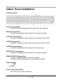
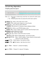
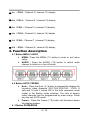
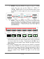
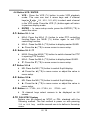
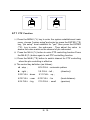
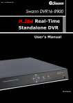
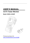
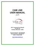
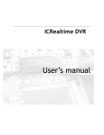
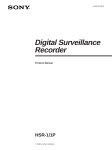
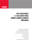
VM-16RT Video
Multiplexer for CCTV
User’s Manual
www.cctvcamerapros.com/cctv-multiplexers
Directory
1.System Features………………………………………………2
2. Rear Panel Installation………………………………………3
3. Front Key Operation…………………………………………4
4. Function description………………………………………..5
4.1Button MENU / AUDIO……………………………………….5
4.2 Button AUTO/ FREEZE………………………………………5
4.3 Button ZOOM/MODE ………………………………………..5
4.4 Button VCR / ENTER………………………………………...6
4.5 Button M4-A / ▲…………………………………………….6
4.6 Button M4-B / ▼…………………………………………….7
4.7 Button M8/◄………………………………………………...7
4.8 Button M9/►……………………………………………..…7
4.9 Button 1/9 / FULL, 2/10 / FULL, 3/11 / FULL…ect………….7
4.10 PAL/NTSC System………………………………………7
4.11 PTZ Function…………………………………………….7
5. Setup Menu Operation………………………………………9
5.1 Setup Main menu…………………………………………10
5.2 System Setup Menu………………………………………10
5.3 Display Setup Menu……………………………………….12
5.4 Camera Setup Menu………………………………………13
5.5 Auto Sequence Setup Menu……………………………..14
5.6 Event Setup Menu………………………………………….15
5.7 Event Report………………………………………………..16
5.8 Event List Clear Menu……………………………………..17
6. RS-232C and RS485 Interface………………………………18
1 / 19
2 / 19
1.System Features
- 4 channel audio input,1 channel audio output
- Connects up to 4/8/16 Video Camera
Adjustable Brightness, Contrast, Saturation, Hue and Sharpness
- High Resolution
720X480 60Hz for NTSC
720X576 50Hz for PAL
- Various Display Modes
4 /8/16 Split Mode
Full Screen Mode
PIP Screen Mode
Realtime 8 Split Mode
Non-realtime 16 Split Mode
Dual Split Mode
Auto Sequence Mode
- High Performance Freeze Function
Flicker Free Image Capture
- High Performance Zoom Function
Selectable Zoom Area
- Various Overlay Information
Camera Title
Real Time and Date
Loss Message
- Playback in DUAL QUAD or Full Screen Image
- Provide Various Event Input and Detection
Video Loss Detection
60 Event Report
Built-in Buzzer and Relay Output
- Remote Control by Infrared Transmitter and RS-232 connection (option)
- Camera Control by RS485 connection (option)
3 / 19
2.Rear Panel Installation
16 Split system
Camera Connection
Accept 16 loop composite video inputs from the camera.
Monitor Connection
Provide 1 composite video output for the main monitor.
VCR OUT Connection
Provide 1 composite video output for recording in the VCR.
VCR IN Connection
Accept 1 composite video input for playback from the VCR.
AUDIO IN Connection
Accept 4 composite audio inputs from the camera.
AUDIO OUT Connection
Provide 1 composite audio output for the main monitor.
RS485 / RS-232 Connection
Provide RS485 interface to control camera.
Provide RS-232 interface to be controlled by HOST.
Power Switch
1 : ON
○ : OFF
Power Jack Connection
DC 12V/1.5A, Center is positive
4 / 19
3.Front Key Operation
16 Split system front panel
Note: (*L) – Press key continuously more than one second to enter menu
options.
(**S) – Press key less than one second to enter menu options.
⑴ MENU (*L) : Enter or Exit main menu mode.
AUDIO (**S) : switch audio channel or turn off audio
⑵ AUTO (*L) : Auto channel switch ON/OFF
FREEZE (**S):Press it to freeze/un-freeze display windows.
⑶ ZOOM (*L) : Enter or exit ZOOM display mode.
MODE (**S) : Enter 16 Split ,picture in picture and Dual Split mode.
⑷ VCR (*L) : Enter Playback function
ENTER (**S) : Enter menu setup
⑸ M4-A / ▲ (*L) : Enter or Exit PTZ control function
M4-A / ▲ (**S) : Master QUAD display / up direction button
⑹ M4-B / ▼(**S) : Slave QUAD display / down direction button/switch
channel for PTZ controlling
⑺ M8/◄ (**S) : 8 Split display / left direction button
⑻ M9/► (**S) : 9 Split display / right direction button
⑼ 1/9 / FULL : Channel 1 ( channel 9) display
⑽ 2/10 / FULL : Channel 2 ( channel 10) display
5 / 19
⑾ 3/11 / FULL : Channel 3 ( channel 11) display
⑿ 4/12 / FULL : Channel 4 ( channel 12) display
⒀ 5/13 / FULL : Channel 5 ( channel 13) display
⒁ 6/14 / FULL : Channel 6 ( channel 14) display
⒂ 7/15 / FULL : Channel 7 ( channel 15) display
⒃ 8/16 / FULL : Channel 8 ( channel 16) display
4. Function description
4.1 Button MENU / AUDIO
● MENU: Press the MENU (*L) button to enter or exit menu
setup.
● AUDIO : Press the AUDIO (**S) button to switch audio
channel to listion in or turn off audio.
4.2 Button AUTO/ FREEZE
● Auto : Press the Auto (*L) button to sequentially display the
turned-on video channels (CH1,CH2,CH3,CH4…..CH16, 8
split and 16 split if turned ON in the Auto sequence setup
mode) in the display mode windows. The time of display
video channels can be programmed by menu setup. Press
any key exit AUTO mode.
● Freeze : Press the Freeze (**S) button will freeze/un-freeze
the display window.
4 .3 Button ZOOM/MODE
6 / 19
●
ZOOM : Press the ZOOM (*L) button to enter 2 * ZOOM
mode. The user can use the “M4-A
/ ▲ “, “M4-B / ▼ “,
“M8/◄“, “M9/►“buttons to move the ZOOM-in frame. Press
the ZOOM (*L) button again will return to previous display
mode.
●
MODE : Press the MODE (**S) to enter the MODE setup
mode. By default, the display modes are circulated as the
following sequence, Non-realtime 16 Split, realtime 8split,2
Picture-in-Picture, 1 Picture-in-Picture and Dual Split for
each MODE key .
ZOOM
MODE
ZOOM
MODE
ZOOM
MODE
ZOOM
MODE
16 Split
8 Split
8 Split
2 PIP
ZOOM
MODE
ZOOM
MODE
1PIP
Dual Split
In 8split and PIP mode, press “ENTER” key enter setup function for
select display channel and channel display area. Press up and down
(▲▼) key to select item to setup . Press left and right(◄►) key to
select which value we needed. Press “ENTER” key again to exit this
setup function.
In two screen compared mode, select any two channel to compared
screens. Press “ENTER” key enter setup function for select display
channel and circle display star area. Press up and down(▲▼) key to
select item to setup. Press left and right(◄►) key to select which
value we needed. Press “ENTER” key again to exit this setup
function.
7 / 19
4.4 Button VCR / ENTER
● VCR : Press the VCR (*L) button to enter VCR playback
mode. The user can use 4 arrow keys and 4 channel
keys(▲,▼,◄,►,1/9,2/10,3/11,4/12) to select each channel
in the VCR mode. Press the VCR (*L) button again will return
to previous display mode.
● ENTER : In menu setup mode ,press the ENTER (**S) to
select the value.
4.5 Button M4-A / ▲
●
●
●
M4-A: Press the M4-A (*L) button to enter PTZ controlling
function.Press the M4-B (*L) button again to exit PTZ
controllling function.
M4-A: Press the M4-A (**S) button to display master QUAD.
▲: Press the ▲ (**S) to move cursor in menu setup.
4.6 Button M4-B / ▼
●
M4-B: Press the M4-B (**S) button to switch channel for PTZ
in opening PTZ function.
● M4-A: Press the M4-A (**S) button to display slaver QUAD.
● ▼: Press the ▼ (**S) to move cursor in menu setup.
4.7 Button M8/◄
●
●
M8: Press the M8 (**S) button to switch 8 split display.
◄: Press the ◄ (**S) to move cursor or adjust the value in
menu setup.
4.8 Button M9/►
●
●
M9: Press the M9 (**S) button to switch 9 split display.
►: Press the ► (**S) to move cursor or adjust the value in
menu setup.
4.9 Button 1/9 / FULL, 2/10 / FULL, 3/11 / FULL…ect.
●
16 channel keys select camera to be displayed as full
screen.
4.10 PAL/NTSC System
System can be defined as NTSC or PAL standard with the
following method. The first method is power on with pressing
7/15 or 8/16 key and the second one is to define in the setup
menu.
8 / 19
Connect Power Cable
Connect Power Cable
7/ 15
8 / 16
FULL
FULL
PAL
NTSC
4.11 PTZ Function
⑴ Press the MENU (*L) key to enter the system establishment main
menu, choose "system setup"and enter by press the ENTER (**S)
key, "ptz setup" must establish for "yes" ,then press the ENTER
(**S) key to enter the sub-menu . Then adjust the value to
ensure the value match as the channel of ptz connected.
⑵ Press the M4-A (*L) button to enter PTZ controlling function.Press
the M4-B (*L) button again to exit PTZ controllling function.
⑶ Press the M4-B (**S) button to switch channel for PTZ controlling
when the ptz controlling is effective
⑷ The control key definition (as follows):
◄:stop;
8/16 FULL:automatic pattern
►:right;
1/9 FULL:left;
2/10 FULL:down
3/11 FULL:up;
(direction)
4/12 FULL: near
5/13 FULL: far
(focal distance)
6/14 FULL: big
7/15 FULL: small
(aperture)
9 / 19
10 / 19
5. Setup Menu Operation
The system provides a built-in GUI setup screen. For each menu, the key
function is described in the lower region to help operation. The following
figure shows the structure of GUI menu.
11 / 19
5.1 Setup Main menu:
Press MENU (*L) key to enter main menu setup.
Move cursor to the item of needed setup with ▲/▼.Press
◄/► to select the value. Press ENTER key to enter submenu.
Press MENU (**S) key to exit last menu.
Press MENU (*L) to exit main menu setup.
5.2 System Setup Menu
1) Press▲/▼ to select the item of setup .Press◄/► to select the value
;
2) DATA:there are three kinds of display format to data:MM-DDYY DD-MM-YY ,YY-MM-DD。Default:YY-MM-DD,07-07-07
3) TIME: time setup. HH:MM:SS is hour, minute and second.
Default:12:00:00.
4) SYSTEM FORMAT:PAL / NTSC. Default :PAL;
5) PTZ SETUP:If select YES, press ENTER to enter PTZ setup.
6) KEY LOCK: key lock. If select NO, after exit menu setup mode, all
key be locked except MENU key.
Default:OFF;
12 / 19
FACTORY RESET: comeback to factory setup. Press ◄/► to
select YES or NO. If select NO, press ENTER to enter into next dialog
box. Press ◄/► to select YES and press ENTER to comeback factory
setup. Default:NO
Factory Reset Menu
FACTORY RESET
WARNING!
THIS SYSTEM GETS TO LOSE
THE CURRENT SETTING VALUE
AND WILL BE INITIALIZED
WITH FACTORY RESET MODE.
ARE YOU SURE?
NO
YES
SELECT
ENTER
13 / 19
MENU EXIT
5.3 Display Setup Menu
DISPLAY SETUP
DISPLAY ON SCREEN
☑
☑
☑
SCREEN POSITION X : 0
Y : 0
BORDER LINE COLOR
BLACK
GRAY1
GRAY2
WHITE
OFF
SELECT
ADJUST
MENU EXIT
① DISPLAY ON SCREEN : Select YES or NO to display
camera title, data time in the screen. Press ▲ / ▼ to move
cursor, press ENTER to change state. Display “√”
② SCREEN POSITION:Select screen display area. X
position: -10 c +10. Y position: -4 ~ +3 . Default(X:0 ,Y:
0).
③ BORDER COLOR:Border colors have black, gray, white
and selected.
Default: GRAY2.
14 / 19
5.4 Camera Setup Menu
CAMERA SETUP
CAMERA : 01
TITLE : CAMERA01
SELECT
ADJUST
BRIGHTNESS
CONTRAST
SATURATION
HUE
SHARPNESS
:
:
:
:
:
0
0
0
0
0
MIRRORING
: OFF
MENU EXIT
Setup each camera’s title / brightness /contrast / saturation / hue /
sharpness and mirroring independently.
① CAMERA:Select the camera with ◄/►.Default: ch1.
② TITLE: Channel name setup. Press ▲/▼ to move cursor to
next character and press ◄/► to change character. Default:
CAMERA1
③ BRIGHTNESS:Brightness setup. From –100 to +100 can
be selected. Press long ◄/► key, value can be continued
changed. Default: 0
④ CONTRAST:Contrast setup. From –100 to +100 can be
changed. Press long ◄/► key, value can be continued
changed. Default: 0
⑤ SATURATION:Saturation setup. From –100 to +100 can be
selected. Press long ◄/► key, value can be continued
changed. Default :0
⑥ HUE : Hue setup. From –100 to +100 can be selected.
Press long ◄/► key, value can be continued changed.
15 / 19
Default :0
⑦ SHARPNESS : Sharpness setup. From 0 to 3 can be
selected. Press long ◄/► key, value can be continued
changed. Default :0
⑧ MIRRORING : Mirroring display camera screen. Default:
OFF
5.5 Auto Sequence Setup Menu
AUTO SEQUENCE DWELL TIME
16 CHANNEL
PAGE A 8
CAMERA1
CAMERA2
CAMERA3
CAMERA4
:
:
:
:
:
:
01
01
01
01
01
01
SEC
SEC
SEC
SEC
SEC
SEC
PAGE B 8
CAMERA9
CAMERA10
CAMERA11
CAMERA12
CAMERA5
CAMERA6
CAMERA7
CAMERA8
:
:
:
:
01
01
01
01
SEC
SEC
SEC
SEC
CAMERA13
CAMERA14
CAMERA15
CAMERA16
SELECT
ADJUST
: 01 SEC
: 01 SEC
: 01 SEC
: 01 SEC
: 01 SEC
:
:
:
:
01
01
01
01
SEC
SEC
SEC
SEC
MENU EXIT
Setup display times of AUTO sequence to each screen. There are
skip/1sec~99sec be selected.
Default: 1sec.
16 / 19
5.6 Event Setup Menu
Setup loss detection independently of channels.
① BUZZER/REKPORT : Control buzzer and relay in alarm,
video loss and motion states. Press ▲/▼/◄/► to select item
o and press ENTER to change state. “√” is ON. Default:
VIDEO LOSS: NO (√).
② BUZZER HOLD TIME:OFF/1ses~99ses can be selected.
Default: 5ses.
③ REPORT HOLD TIME:Report of relay.
④ Holding time. OFF/1ses~99ses can be selected. Default:
30sec.
17 / 19
5.7 Event Report
EVENT REPORT
1 OF 6 PAGE
NO
YY-MM-DD
HH:MM:SS
CH
EVENT
1
07-07-30
16:56:03
1
LOSS
2
07-07-30
16:56:03
2
LOSS
3
4
5
6
7
8
9
10
07-07-30
07-07-30
07-07-30
07-07-30
07-07-30
07-07-30
07-07-30
07-07-30
16:56:03
16:56:03
17:56:03
17:56:03
17:56:03
17:56:03
18:56:03
18:56:03
3
4
1
2
3
4
1
2
LOSS
LOSS
LOSS
LOSS
LOSS
LOSS
LOSS
LOSS
LIST CLEAR : NO
SELECT
SELECT PAGE
MENU EXIT
Display every report of alarm. Event report has 6 page totally and
10 recordings per page. Press ◄/► to change pages.
LOSS: video loss.
ALARM: exterior alarm
MOTION: motion detection.
LIST CLEAR: Clear the list of reports.
18 / 19
5.8 Event List Clear Menu
LIS T C LE AR
WAR NI NG!
THI S S YS TEM G ETS T O L OS E
THE CU RR ENT E VEN T LIS T
AND WI LL BE I NIT IA LIZ ED
WIT H B LI NK.
A RE YO U SUR E?
YES
NO
SEL ECT
E N TE R
19 / 19
M E NU EXI T
6. RS-232C and RS485 Interface
The host providing RS-232C interface can control this system remotely.
Receiving can be worked by 9600bps.
The detail receiving protocol are explained in Receive Protocol section.
System accepts only 1 byte to get commands from host .
Connection as follow:
The Explanation of connection as follow:
① Ground must be connected into together : The 5th foot of the serial
port connect to the 1th foot of the RS485/RS232 connection .
② The 3th foot of the serial port connect to the 3th foot of the
RS485/RS232 connection .
③ The 2th foot of the serial port connect to the 2th foot of the
RS485/RS232 connection .
20 / 19
Receive Protocol
Byte
1st
7
1
6
0
5
4
3
2
1
0
KEY
KEY
0
1
2
3
4
5
6
7
8
9
10
11
12
13
14
15
Description
NULL
Channel 1
Channel 2
Channel 3
Channel 4
Channel 5
Channel 6
Channel 7
Channel 8
Channel 9
Channel 10
Channel 11
Channel 12
Channel 13
Channel 14
Channel 15
KEY
21
22
23
24
25
26
27
28
29
30
31
32
33
34
35
36
Description
A Page 8 Unite
B Page 8 Unite
A Page 9 Unite
B Page 9 Unite
Non-realtime 16 Split
8 A Page
8 B Page
2 Picture-in-Picture
1 Picture-in-Picture
Dual Split
Auto Sequence
Playback
Freeze
Zoom
Menu
16
Channel 16
37
▼
17
18
19
20
Quad A Page(1-4)
Quad A Page(5-8)
Quad B Page(1-4)
Quad B Page(5-8)
38
39
40
41~63
Enter
No operation
21 / 19
▲
FREEZE 1
POWER
VCR
MENU
QUAD/ENTER
AUTO
CAM3/+
CAM4/ZOOM
3
2
4
CAM1/▲
CAM2/▼