1
USFOS USER’S MANUAL
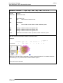
Input Description USFOS Control Parameters
6.1-1
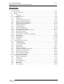
Table of Contents
6
Input Description....................................................................................................................... 6.1-1
6.1
General information .......................................................................................................... 6.1-1
6.2
Formats.............................................................................................................................. 6.2-1
6.2.1
Comments ................................................................................................................. 6.2-1
6.3
User input descrition ......................................................................................................... 6.3-1
6.3.1
General ...................................................................................................................... 6.3-6
6.3.2
Load control .............................................................................................................. 6.3-8
6.3.3
Dynamic Modelling Parameters.............................................................................. 6.3-18
6.3.4
Analysis Control Parameters ................................................................................... 6.3-26
6.3.5
Numerical Procedure Parameters ............................................................................ 6.3-30
6.3.6
Material/Plasticity Modelling.................................................................................. 6.3-32
6.3.7
Member Modelling.................................................................................................. 6.3-37
6.3.8
Joint Modelling ....................................................................................................... 6.3-47
6.3.9
Foundation Modelling ............................................................................................. 6.3-58
6.3.10 Fracture/Ductility Control ....................................................................................... 6.3-69
6.3.11 Fire(Temperature Response) Analysis .................................................................... 6.3-71
6.3.12 Ship Impact analysis................................................................................................ 6.3-79
6.3.13 External pressure Effects......................................................................................... 6.3-84
6.3.14 Super-element / Sub-structure Modelling ............................................................... 6.3-86
6.3.15 Miscellaneous.......................................................................................................... 6.3-92
6.3.16 Hydrodynamics ..................................................................................................... 6.3-100
6.3.17 Aerodynamics........................................................................................................ 6.3-124
6.3.18 Earthquake............................................................................................................. 6.3-131
6.4
Sesam structural File Format............................................................................................. 6.4-1
6.4.1
Geometry Data .......................................................................................................... 6.4-3
6.4.2
Connectivity Data...................................................................................................... 6.4-4
6.4.3
Cross Sectional Data ................................................................................................. 6.4-6
6.4.4
Element Data ........................................................................................................... 6.4-11
6.4.5
Material Data........................................................................................................... 6.4-12
6.4.6
Boundary Conditions............................................................................................... 6.4-14
6.4.7
Load and Temperature Increments.......................................................................... 6.4-17
6.4.8
Hydrodynamic Added Mass.................................................................................... 6.4-23
6.4.9
Nodes with point masses ......................................................................................... 6.4-24
6.4.10 Nodes with inital conditions.................................................................................... 6.4-25
6.4.11 Super-element definition ......................................................................................... 6.4-26
6.5
UFO Structural File Format .............................................................................................. 6.5-1
6.5.1
Analysis identification............................................................................................... 6.5-4
6.5.2
Nodal Data................................................................................................................. 6.5-4
6.5.3
Element Data ............................................................................................................. 6.5-9
6.5.4
Cross Section Data .................................................................................................. 6.5-22
6.5.5
Material Data........................................................................................................... 6.5-26
6.5.6
Misc Data ................................................................................................................ 6.5-32
6.5.7
UFO Examples ........................................................................................................ 6.5-34
2010-01-01
USFOS USER’S MANUAL
Input Description USFOS Control Parameters
6.1-1
6 INPUT DESCRIPTION
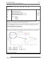
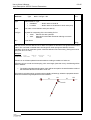
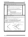
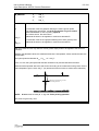
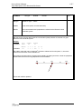
USFOS reads input from symbolic files.
The user may give all input on one file, or distribute the data on two or three files. All control
parameters are specified in the Analysis Control File. Structure data can also be read from this file, but is
usually given on one or two separate files. The specific content of these files is not important, as long as
all data are present. For convenience, these files are labelled "Structure file" and "Load file", cfr Figure
2.1.
These files may be written with a text editor, or generated by interactive preprocessor and load
generation programs.
USFOS is currently adapted to the SESAM analysis system, and reads structure data and load data
generated by the programs PREFRAME, WAJAC and WALOCO /3-5/.
The input records specific for USFOS nonlinear analysis are presented in Section 6.3. Structure input
and load input are presented in Section 6.4.
6.1 GENERAL INFORMATION
The input data are organized in records, each record starting with a record identifier of four to eight
characters. Each record may consist of one or more lines of data, terminating on the next record
identifier. Each line may be up to 132 characters long. The data items may be integer on real data.
The data records may be given in an arbitrary order.
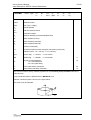
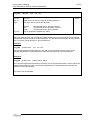
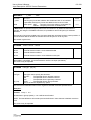
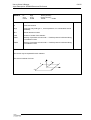
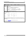
In this manual, each record is presented in a standard frame. Each frame represents either one single
record or a sequence of similar records.
2010-01-01
6.2-1
USFOS USER’S MANUAL
Input Description USFOS Control Parameters
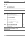
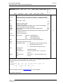
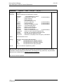
RECORD_IDENTIFIER Param_1 Param_2 Param_3 ... Param_n
Parameter
Description
Param_1
Description of 1st parameter
Default
Param_2
Description of 2nd parameter
values
Param_3
Description of 3rd parameter
if
...
Default
applic-
Param_n
Description of n'th parameter
able
Optional box for comments, notes, exceptions etc
6.2 FORMATS
Nearly all input data are read by SAM/FII, a FORTRAN free-format reader and decoder. This means
that the data items may be written anywhere on the line, as long as the specified order is satisfied. The
data items must be separated with at least one blank (exceeding blanks are ignored). Note that blank is
exclusively interpreted as a delimiter, and can not be used to specify a zero value as accepted by standard
FORTRAN READ.
Important:
All digits, letters and/or special symbols in a data item must be given consecutively without blanks.
6.2.1
Comments
Lines with following characters in the first column are interpreted as comments, and are simply ignored.
Comments may occur anywhere in the input data stream.
'
*
#
%
!
Example:
'THIS IS A COMMENT
# NOTE! COMMENTS ARE IGNORED BY THE PROGRAM
2010-01-01
6.2-2
USFOS USER’S MANUAL
Input Description USFOS Control Parameters
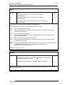
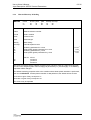
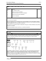
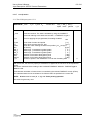
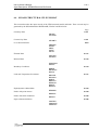
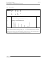
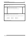
In-Line Comments:
The character ! may be used to terminate a data line, and data items on the rest of the line are just
ignored.
Example:
#
#
Mat_ID
MISOIEP 1
MISOIEP 2
#MISOIEP 2
E-mod poiss F_yield
2.10E+5 0.3
355
2.10E+5 0.3
340
2.10E+5 0.3
300
Density
8235.7
8235.7
8235.7
therm.exp.
0.0
0.0
! NEW 96-02-13
0.0
! OLD 96-02-13
This is a useful option in connection with modification/correction of input files.
Alphanumeric Data Items
An alphanumeric data item may consist of one or more characters. The first character is always a letter
(A-Z), while the remaining ones may be letters, digits or special symbols (except /, $, & and blank).
There is no upper limit to the number of characters in an alphanumeric data item. However, only the
first 8 characters will be decoded, and all characters in excess of this are simply ignored.
Integer Data Items
- All characters must be digits
The first digit may be preceded by + or Example:
0
1
-27
+66
Real Number Data Items
Real numbers data entry may consist of up to 3 components, i.e. an integer part i, a decimal part d, and
exponent part e. The following 4 basic forms are accepted:
(±)i
(±)i.
(±)i.d
(±).d
These may all be combined with exponent parts yielding the forms:
(±)iE(±)e
(±)i.E(±)e
(±)i.dE(±)e
(±).dE(±)e
Example:
0
+1.
-0.2E14 +17.E-3 1.8E+3
2010-01-01
6.2-3
USFOS USER’S MANUAL
Input Description USFOS Control Parameters
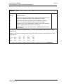
Text Strings
Text strings may consist of one or more characters, which may be letters (A-z), digits or special symbols.
72 characters are stored in a text string, beginning at the 9th character of the line.
Example:
This text string uses special characters & \ #
and will be stored as
t string uses special characters & \ #
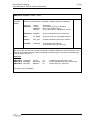
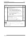
Numerical Operations on the Input
Some simple numerical operations is interpreded by the FII input reader. This means that the user may
define mathematical expressions in the input, for example in order to scale paremters. The
expressions are:
•
•
•
•
•
Adding
Subtraction
Multiplication
Division
Trig
(+)
(-)
(*)
(/)
(SIN(ang) and COS(ang), ang in radians)
Example 1, Scaling the yield stress:
MISOIEP 10 210000E6 0.3
355E6/1.15 7850 1.4E-5
! Material coeff 1.15 (ULS)
Example 2, Adding value to coordinate :
‘
NODE
ID
10
X
0.0
Y
10.0+1.23
Z
10.0
! Add 1.23 to the Y-coordinate
Example 3, Create a loadvector (1MN) depending on angle (here 30 degrees)
‘
NODELOAD
lCase
3
NodID
10
Fx
1.0E6*COS(30*PI/180)
Fy
Fz
1.0E6*SIN(30*PI/180) 0.0
2010-01-01
6.3-1
USFOS USER’S MANUAL
Input Description USFOS Control Parameters
6.3 USER INPUT DESCRITION
This section describes the input records specific for USFOS nonlinear analysis.
information MUST be supplied
The following
• inelastic material properties MISOIEP
(if the yield stress is not speficied in the structure file)
• control node(s)
CNODES
• loadcontrol
CUSFOS
(static analysis)
...or... CICYFOS
(cyclic analysis)
...or... DYNAMIC + LOADHIST + TIMEHIST
(dynamic analysis)
Remaining input records are optional.
In general, it is recommended to locate the “USFOS control parameters” in the “control file” (the “head
file”)
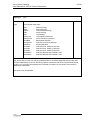
General
Page 6.3-6
Analysis identification
* HEAD
Print control
Data storage
Save additional data for XACT presentation
CPRINT
CSAVE
* XFOSFULL
1st line of text identifying the analysis
2nd line of text identifying the analysis
3rd line of text identifying the analysis
inprint outprint termprint
restart result print
Load control
Page 6.3-8
Static analysis
Cyclic (static) analysis
CUSFOS
CICYFOS
nloads
lcomb
lcomb
:
:
lcomb
nloads
lcomb
lcomb
:
:
lcomb
npostp
lfact
lfact
:
:
lfact
npostp
lfact
lfact
:
:
lfact
mxpstp
mxld
mxld
:
:
mxld
mxpstp
mxld
mxld
:
:
mxld
mxpdis
nstep
nstep
:
:
nstep
mxpdis
mxdisp
mxdisp
:
:
mxdisp
minstp
minstp
:
:
minstp
nstep
nstep
:
:
nstep
minstp
minstp
:
:
minstp
Load combination
Control displacement
COMBLOAD new_case oldcase1 fac1 oldcase2 fac2 ……
CNODES
ncnods
nodex idof
dfact
nodex idof
dfact
:
:
:
:
:
:
nodex idof
dfact
Static analysis, time history format
Dynamic analysis, time history format
Time history definition by points
Time history definition by Swith
Time history definition by S_Curve
Time history definition by Sine Curve
Time history definitions by points with const dT
STATIC
DYNAMIC
TIMEHIST
TIMEHIST
TIMEHIST
TIMEHIST
TIMEHIST
end_time
inc
dT_res d_Tterm mxdisp nstep
end_time
delta_t dT_res dT_term
histno Point time1 factor1 time2 factor2 ...
histno Switch dTime Factor T_start
histno S_Curve T1
T2 Factor
Power
histno Sine
Amp Per Phase
(tStart nPer)
histno ConstInc dTime fac1 fac2 fac_n
Dynamic analysis, load specification
Initialization Time
LOADHIST
INI_TIME
l_case time_hist
T_ini
minstp
2010-01-01
6.3-2
USFOS USER’S MANUAL
Input Description USFOS Control Parameters
Dynamic Modelling Parameters
Page 6.3-18
Structural damping - Rayley
Structural damping - time dependent
Damping Parameters. General
Element Damping
Mass formulation - lumped
Mass formulation - consistent
System Damping Formulation Switch
Initial velocity
Dynamic result. Nodal data
Dynamic result. Element data
Dynamic result. Global data
RAYLDAMP
DAMPRATIO
DAMPDATA
ELEMDAMP
LUMPMASS
CONSIMAS
SYSDAMP
INI_VELO
DYNRES_N
DYNRES_E
DYNRES_G
alpha1
alpha 2
Ratio 1 Ratio 2 Freq1 Freq2
History
Dammp_ID
Type
( data )
Dammp_ID
ListType
( ID-list )
rotmas
Switch
Type
Type
Type
Type
Time Vx Vy Vz rVx rVy rVz Id_1 Id_2
Node_ID
Dof (Node_2
Dof_2)
Elem_ID
End Dof
(opt)
Analysis Control Parameters
Page 6.3-26
Program parameters
Switch off 2 Surface model
Switch off Arc Length Control
Switch off Determinant check
Local Dent Formulation
Switch off Local Dent formulation
Override default max number of steps
Eigenvalue analysis
Bifurcation analysis
CPROPAR
SURF2OFF
ARC_OFF
DETEROFF
DENT_TYPE
DENT_OFF
CMAXSTEP
EIGENVAL
CBIFURC
epssol gamstp ifunc pereul ktrmax dentsw cmax ifysw detersw
type
max_step
KeyWord
idcomb idstep
Value
ibifsw
Numerical Procedure Parameters
Page 6.3-30
Iteration control
Iteration control “Light Version”
Control of repeated plastification/unloading
Time integration parameters
Predictor-corrector method
Direct implicit time integration
CITER
LITER
CUNFAL
CDYNPAR
PCOR_ON
PCOR_OFF
cmin cneg
itmax
max_on/off
alpha beta
itmax
isol
epsit
cmineg
gamma
Material/Plasticity Modelling
Page 6.3-32
Elasto-plastic material (beam-column)
Control of cross section yield surface size
Nonlinear spring definition
(spring property references)
Elastic-to-plastic transition parameters
and hardening parameters
Elastic-to-plastic transition parameters
and and hardening parameters
MISOIEP
GBOUND
MREF
matno E-mod poiss
zbm
geono zym
matno refx
refy
MPLASMON matno c1
c4
MPLASCYC matno c1
c4
a1
a4
a1
a4
yield
zyc
refz
density
zbc
refrx
term.exp
refry
refrz
c2
c5
c2
c5
a2
a5
a2
a5
c3
c6
c3
c6
a3
a6
a3
a6
Member Modelling
Page 6.3-37
Control of plastic hinges in members
Control of plastic hinge (alt. input)
Internal Hinge of Beam Elements
Define member initial imperfection groups
Assign initial imperfection to member
Linear dependencies/ Shim elements
Non-structural members
Structural members (override NONSTRU)
Linear Elements
Beam type definition
CELHINX
elnox ihin1
ihin2
PLASTHIN ihin1 ihin2
ihinm
BEAMHING ix1
iy1
iz1
ix2
iy2
iz2
GIMPER
impgrp impshpe angle
GELIMP
elnox impgrp
BLINDP2
insl
iem
ix
NONSTRU
ListType
STRUCTEL ListType
LIN_ELEM Form ListType
BEAMTYPE Type ListType
Analysis Calibration - Initial deformations
Initial deformation from Eigenvalue analysis
Grouted Members
Local Element Transformation Update
CINIDEF
BuckMode
Grouted
ElmTrans
ihinmid
elnox1
irx1
irx2
offset
elnox2
iry1
iry2
dent1
iy
iz
[ List ]
[ List ]
[ List ]
[ List ]
.....
irz1
irz2
dent2
elnox1 elnox2 ....
dentmid
irx
iry irz
Size/ColumnCurve
Pattern
LoadCase
EigenMode no
Scale Factor
GroutMatID
ListType
{ IDList }
Type nod/end ListType
{ IDList }
2010-01-01
6.3-3
USFOS USER’S MANUAL
Input Description USFOS Control Parameters
Joint Modelling
Page 6.3-47
Joint flexibility
Overlapping braces at joint with
local flexibility specified
Joint capacity check - minimum input
Joint capacity check - extended input
SHELL
OVERLAP
nodex elnox1 elnox2 d
nodex elnob1 elnob2 ....
CHJOINT
CHJOINT
Joint capacity check – MSL char.
Surface Size for Joints
User Defined Joint Gap
Joint Capacity Formulation
Joint Classification Interval
Control of plastic hinges at nodes
CHJOINT
JSURFSIZ
JOINTGAP
JNT_FORM
JNTCLASS
CNOHINX
nodex elnox1
nodex elnox1
alpha1 alpha2
brace1 axial
brace2 axial
:
:
bracen axial
nodex elnox1
Size_Y Size_B
Gap
NodeID
form_no
interval
nodex hinmx
t
elnox2 geono
elnox2 geono CapRule
alpha3 alpha4 alpha5 nbraces
torsion Mipb Mopb
torsion Mipb Mopb
:
:
:
torsion Mipb Mopb
elnox2 geono CapRule CapLevel
nodex1 nodex2 ...
(brace1 brace2 ..)
{ NodeID_List }
Qf
Foundation Modelling
Page 6.3-58
Spudcan element
SPUDMAT
MSPUD
Pile elements
PILE
Pile geometries (Single Pile)
Pile geometries (Pile Group)
PILEGEO
PILEGEO
matno Type
matno R
v
Vpre
C8
ID
Nodex1
Pile Geo
ID
Type
ID
Type
ß
GV
γ
GH
φ
GR
c
YFSW
Nodex2 Soil_ID Pile Mat
Local_coord
Imper
Do
T
Do
T
nPile
y_loc1 z_loc1
y_loc2 z_loc2
........
........
y_locn z_locn
Depht varying Pile Diam. and Thickn.
PILE_D-T
ID
Z_Mud Z_top1
Z_top2
......
Z_topn
Z_bott1
Z_bott2
.....
Z_bottn
(Do T)1
(Do T)2
.............
(Do T)n
Depht varying Soil Diam.(override default)
SOILDIAM
ID
Z_Mud Z_top1
Z_top2
......
Z_topn
Z_bott1
Z_bott2
.....
Z_bottn
(Do Dummy)1
(Do Dummty2
.............
(Do Dummy)n
Soil characteristics
SOILCHAR
ID
Type
Nonlinear Soil Spring Model
Spring Damping (Dashpot)
Automatic calculation of P-Y, T-Z and Q-Z
SPRI_MOD
SPRIDAMP
API_SOIL
model
DoF C
Elem_1 Elem_2……..
ID
Soiltype LoadType
{Data}
Z_Mud D_ref
F_fac
L_fac Z_top1
Z_top2
Z_top3
......
Z_topn
Z_bott1<Data>1
Z_bott2<Data>2
Z_bott3<Data>3
.....
.............
Z_bottn<Data>n
Fracture/Ductility Control
Page 6.3-69
Fracture check switch
Fracture criterion definition
User defined member fracture
CFRACT
MFRACT
USERFRAC
matno crit-ctod σu
εu
elnox Type
<Crit.>
εsa
2010-01-01
6.3-4
USFOS USER’S MANUAL
Input Description USFOS Control Parameters
Fire(Temperature Response) Analysis
Page 6.3-71
Member temperature fields
Member temperature fields
Temperature fracture check switch
Temperature fracture criterion definition
Temperature dependent material properties,
- steel
- aluminum
- user-defined reduction curve
- user-defined material
Load-case vs. time definition
Fire Collapse check
tygrad
tzgrad
BELTEMP
llc
elnox t0
ELEMTEMP llc
type
[data_set] iel1 iel2
CTFRACT
TFRACT
matno T-fract Sy-fract E-fract
STEELTDEP
ALUMTDEP
TDEPFUNC
USERTDEP
LCASETIM
FIRECHK
curve_no
curve_no
curve_no
mat_no dep_E
l_case time
LCase_Chk
(PFPCrackAng)
iel3
.....
mat no 1 mat no 2
........
mat no 1 mat no 2
........
type
[Data]
dep_yield
dep_plasticdep_exp.
YieldRed
ERed
TempLim
Ship Impact analysis
Page 6.3-79
Ship impact
Ship indentation characteristics
Dynamic ship impact
BIMPACT
ldcs
MSHIP
DYNIMPCT ldcs
Multiple impact Switch
MULT_IMP
elnox
ship
elnox
elpos
p1
elpos
energy extent xdir ydir
p2
p3
d1
V_ship Mass xdir ydir
NL_ship
Time
zdir
ship
zdir
External pressure Effects
Page 6.3-84
External hydrostatic pressure
Sea surface elevation
EXTPRES
SURFLEV
elnox1 elnox2 elnox3 .....
hisurf losurf density gravity
Super-element / Sub-structure Modelling
Page 6.3-86
Super elements
Sub-structure analysis
Shell sub-structure generation
Shell sub structure load
Define mesh density for pipe
Define mesh density for box
Define mesh density for I/H profile
SUPERELM Elem ID
nNodes Nodex_1
Nodex_2
....
Nodex_n
Material
SUBSTRU
Matno
SUBSHELL Elem_ID
SSH_LOAD Lcase Elem_ID Fx Fy Fz Typ Xc Phi_c ExtentX ExtentArc
MESHPIPE nLength nCirc
ElemID(s)
MESHBOX nLength nSide nTop nBott
ElemID(s)
MESHIPRO nLength nWeb nTop nBott
ElemID(s)
Miscellaneous
Page 6.3-92
'Mating' analysis/activation of members
Total load -> Incr. load preprocessing
Distributed load in local element system
Sliding Interface (contact search)
Make non-linear springs invisible
Element Group definition
Add node(s) to a given group
Redefine element material
Redefine boundary conditions
Special Switches
ACTIVELM
TOTL2INC
COROLOAD
SI
* INVISIBLE
GROUPDEF
GROUPNOD
CHG_MAT
CHG_BOUN
SWITCHES
ListType
lc-start lc-end
I_Case Elem_1
Type nMst nSlv
ListType
GroupID
GroupID
MatID
ix iy iz irx iry irz
KeyWord
l_case
elnox1
elnox2 ......
Elem_2 .......
{ Mst ID’s } {Slv ID’s}.
Id_1
Id_2 ......
ListType
[ List ]
Nod_1 Nod_2 ……. Nod__n
Typ
{ID list}
Typ
{ID list}
SubKey { Value }
2010-01-01
6.3-5
USFOS USER’S MANUAL
Input Description USFOS Control Parameters
Hydrodynamics
Page 6.3-100
Wave Definition
WAVEDATA
l_case
type
height
period
dir
Current depth-profile
CURRENT
l_case
speed
dir
surflev
depth
Current time dependency
CURRHIST
Account for relative velocity
Print of waveloads
Marine Growth profile
Defintion of Cd and Cm element by elem
Defining Cd by depth profile
Defining Cm by depth profile
Wave Kinematics Reduction Factor
REL_VELO
WAVCASE1
M_GROWTH
HYD_CdCm
HYDRO_Cd
HYDRO_Cm
Wave_KRF
Wave_KRF
Wave_KRF
BUOYANCY
FLOODED
FLOODED
MAXWAVE
MAXWAVE
WAVMXSCL
WET_ELEM
WAVE_INT
WAVE_INT
WAVE_INT
CURRBLOC
CURRBLOC
BUOYHIST
BUOYFORM
INTFLUID
SPOOLWAV
NONHYDRO
HYDROPAR
Time_1 f1
...
...
Time_n fn.
nAvrg
l_case1 iTotal
Z1
Add
T1
Z2
Add T2
Cd
Cm
Elm_1 Elm_2 ......
Z1
Cd1
Z2
Cd2
......
Z1
Cm1
Z2
Cm2
......
Factor
Factor ListType ID’s ….
Factor Profile….
l_case Write
Elm_1 Elm_2 Elm_3 .........
ListType ID’s …
Criterion
dT
EndT
Write
Keyword
LoadCase(s)
Scale
All
NIS
Elem_1 Elem_2 Elem_3 ..........
NIS
ListType ID’s ….
NIS
Profile….
Type
[Data]
Profile….
HistID ListType
{IDlist}
Form
ListType
{IDlist}
Density FillTyp HistID ListType {IDlist}
TimeBeforePeak Order dT StormLength Crit
ListType
{IDlist}
KeyWord
Value ListType {IDlist}
Wind Definition New Syntax
Wind History
Wind Cross Sect Basic Coefficients
Wind Cross Sect Coefficients. Combine
Assign Coefficients.to Element
WINDFIELD
WINDHIST
W_COEFFS
W_COEFFS
ELMCOEFF
l_case
DOF
ID
ID
ID
Type Ux Uy Uz Zo Zbott Rho power
Hist_ID
Type { Data }
Combine ID_drag ID_lift ID_mom
ListType IDs
Wind Definition Old syntax
WINDFIELD
l_case
T_ini
Aerodynamical parameters for cross sections
WINDPAR
Compute Max Wind
Max Wind options
Buoyancy Switch
Flooded Members
Wave load preprocessing
Wavel load scaling (due to units)
Switch ON hydro checking for all elem
Wave load integration points
Current Blockage Factor
Buoyancy History
Buoyancy Formulation
Internal Fluid / Free Surface Calculation
Spooll Irregular Wave to Peak
Non Hydrodynamic Elements
Hydrodynamic Parameters (Powerful)
phase surflev
X1
....
Xn
Z1
....
Zn
depth n
f1
...
fn.
f1
...
fn.
......
Aerodynamics
Page 6.3-124
Z_bott U10
power rho
WO_x WO_y WO_z
alpha beta
gamma n_ini
GeoID Type
height
np_t np_d
Ct ......
Cd .....
Cl ......
Cm ...
MAXWIND
MAXWIND
Criterion
Keyword
dT EndT Write
lCase .
NODEDISP
NODEVELO
NODEACC
SOILDISP
SOILACC
l_case
l_case
l_case
l_case
l_case
width
np_l np_m
Earthquake
Page 6.3-131
Prescribed nodal displacement
Prescribed nodal velocity (dynamic only)
Prescribed nodal acceleration (dynamic only)
Prescribed Soil displacement
Prescribed Soil acceleration (dynamic only)
dof_code
[Prescribed values for the dofs]
dof_code
[Prescribed values for the dofs]
dof_code
[Prescribed values for the dofs]
Type(=2) Pile_ID dof_code
[ values for the dofs]
Type(=1) z_Top z_Bott dof_code [ values for the dofs]
2010-01-01
6.3-6
USFOS USER’S MANUAL
Input Description USFOS Control Parameters
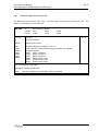
6.3.1
General
HEAD
1st line of text identifying the analysis
2nd line of text identifying the analysis
3rd line of text identifying the analysis
Character 9 to 80 from each line are stored as text strings
This record (of three lines) is given only once
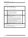
CPRINT
inprint outprint termprint
Parameter
Description
inprint
Code to specify amount input verification print
0:
1:
2:
3:
4:
5:
outprint
2:
3:
4:
termprint
2
Global history output
Results of each load step. Control node displacements
Status of heavily stressed elements
(Γ > -0.20)
+ Status of heavily stressed elements (Γ > -0.50)
+ Status of all elements
(Γ > -1.00)
+ All nodal displacements
Code to specify output to terminal / batch log file
0:
1:
1
Analysis identification, Key parameters and Load control data
+ Structural data
+ Input load data
+ Calculated load data (i.e. gravity)
+ Ecco of unprocessed input data
+ Internal FEM parameters
Code to specify amount of analysis print-out
0:
1:
Default
1
Screen output adapted to interactive running
Output adapted to batch running. The global history output is written
to the batch log file
This record controls the amount and format of print to terminal and to the Analysis Print File (Sect 8.1)
The data available for post-processing are unaffected by this record
This record is given only once
2010-01-01
6.3-7
USFOS USER’S MANUAL
Input Description USFOS Control Parameters
n
CSAVE
m
k
Parameter
Description
Default
n
Restart data is stored every "n'th" load step of each load
case/combination
0
m
Result data is stored every "m'th" load step of each load
case/combination
-10
k
Result data is printed at the 'out-file' every "k'th" step of each load
case/combination
1
This record is used to specify storage of restart and result data
If this record is skipped, restart + result data are stored for every step
If n = 0
If n = -i
then no restart data will be stored
then restart data will be stored every i'th step plus at the end of each load specification,
(CUSFOS/CICYFOS-line)
If m = 0 then no result data will be stored
If m = -j then result data will be stored every j'th step plus at the end of each load specification,
(CUSFOS/CICYFOS-line)
If k = 0
If k = -k
then no result data will be printed at the out-file
then result data will be printed every k'th step plus at the end of each load specification,
(CUSFOS/CICYFOS-line)
NOTE ! In connection with dynamic analysis the parameters n, m and k are 0/1 switches. The time
increment between result saving is controlled on the DYNAMIC record.
By default the switches are set to [ 0 1 1 ].
This record is given only once.
XFOSFULL
Parameter
Description
Default
If this record is specified, (no parameters), all available data are stored on
the raf-file for inspection by XACT.
By default, (to save disc space), some result types are not stored.
With this record the user may specify that all available result data should be stored on the raf-file.
This record is given once.
2010-01-01
6.3-8
USFOS USER’S MANUAL
Input Description USFOS Control Parameters
6.3.2
Load control
CUSFOS
nloads
lcomb
lcomb
:
:
lcomb
npostp
lfact
lfact
:
:
lfact
mxpstp
mxld
mxld
:
:
mxld
mxpdis
nstep minstp
nstep minstp
:
:
:
:
nstep minstp
Parameter
Description
nloads
Number of load specifications (lcomb+lfact+mxld+nstep+minstp). Used in
connection with restart of analyses (Sect 4.7)
npostp
Number of load steps in the post collapse range
mxpstp
Max load step size in the post collapse range
mxpdis
Max incremental displacements in the post collapse range. Suggested
value is 1.0
lcomb
Load combination or load case number
lfact
Load factor. Size of the initial (unscaled) load increment specified as a
factor of the reference load
mxld
The current load vector is repeated until the accumulated load reaches
the relative load level mxld, specified as a factor of the reference load
nstep
... OR until the current load vector has been incremented nstep times.
Both mxld and nstep may be specified at the same time; the load is
incremented until either of the conditions are satisfied. For a zero value of
mxld or nstep no test of upper limit is performed
minstp
Minimum load increment for automatic load step scaling. Specified as a
fraction of the total load combination or load case. (Not multiplied by
lfact). Suggested value is 0.001*mxld, where mxld is the maximum of the
mxld's within the actual load combination
Default
This record is used to specify the loading history, with load and displacement control parameters
(Sect 4.1 and Sect 4.2.2)
Note!
In a restart analysis the load history up to the step from which calculations resumes must
NOT be included in the CUSFOS record
This record is given only once and no default values exist
2010-01-01
6.3-9
USFOS USER’S MANUAL
Input Description USFOS Control Parameters
CICYFOS
nloads
lcomb
lcomb
:
:
lcomb
npostp
lfact
lfact
:
:
lfact
mxpstp
mxld
mxld
:
:
mxld
mxpdis
mxdisp nstep
mxdisp nstep
:
:
:
:
mxdisp nstep
minstp
minstp
:
:
minstp
Parameter
Description
nloads
Number of load specifications (lcomb+lfact+mxld+nstep+minstp). Used in
connection with restart of analyses (Sect 4.7)
npostp
Number of load steps in the post collapse range
mxpstp
Max load step size in the post collapse range
mxpdis
Max incremental displacements in the post collapse range. Suggested
value is 1.0
lcomb
Load combination or load case number
lfact
Load factor. Size of the initial (unscaled) load increment specified as a
factor of the reference load
mxld
Max load level for current load vector (Sect 4.1)
mxdisp
Max total displacement for current load vector
nstep
Max number of load steps for current load vector
minstp
Minimum load increment for automatic load step scaling. Specified as a
fraction of the reference load combination or load case. Suggested value
is 0.0001*mxld, where mxld is the max in the actual load combination
Default
This record is used to specify the loading history, with load and displacement control parameters
(Sect 4.1 and Sect 4.2.2). The current load vector (Sect 4.1) is incremented until the accumulated
load reaches the load level defined by mxld, OR until the total displacement reaches the
displacement level defined by mxpdis, OR when the load vector has been incremented nstep times
If a zero value is given for one (but not all) of the mxld, mxdisp or nstep parameters, that parameter is
disregarded
To run an input check simply specify zero values for both mxld, mxdisp and nstep. That is, the
specified load vector will be incremented zero times
Note!
In a restart analysis the load history up to the step from which analysis resumes must be
excluded. This record is given only once and no default values exist
2010-01-01
USFOS USER’S MANUAL
Input Description USFOS Control Parameters
COMBLOAD
6.3-10
Comb_Case
L_Case1
L_Case2
L_Case3
Factor1
Factor2
Factor3
L_Casen
Factorn
Parameter
Description
Default
comb-case
L_case1
The result of the combination is collected in a load case with number (ID)
= Comb_Case. This case is referred to in USFOS (CUSFOS or LoadHist).
Original definition of this case (if any) is override.
First Load_Case contributing to the combination.
Factor1
The loads in this load_case are multiplied with Factor1 etc.
With this record, the user defines a load combination to be generated and referred to in a USFOS
analysis. This option replaces the old ccomb option, (which had limitation on number of cases and no
individual scaling available).
Example:
‘
COMBLOAD
New Case
3
OldCase
4
3
10
13
Factor
1.3
2.0
0.7
-0.55
Generates a new load case 3 as follows:
l_case3 = (l_case4 * 1.3 + l_case3*2.0 + l_case10*0.7 - l_case13 *0.55)
The original loads, (case 4, 3, 10 and 13), are cleared after all combinations are processed.
NOTE! This option should be used for basic loads only (NodeLoad, BeamLoad, Pressure, Gravity).
This record may be repeated.
2010-01-01
USFOS USER’S MANUAL
Input Description USFOS Control Parameters
CCOMB
lcomb
ldcs1
ldcs2
6.3-11
ldcs3
Parameter
Description
Default
lcomb
Load combination number
ldcs1
First loadcase to enter the load combination
ldcs2
Second loadcase to enter the load combination
ldcs3
Third loadcase to enter the load combination
This record is used to combine input load cases into load combinations. In nonlinear analyses, the
load responses may NOT be superposed. Any superposition must apply to the loads themselves
(Sect 4.1)
If no CCOMB records are given, the program will use the input load case numbers. However, if this
record is used once, then all load specification will refer to load combination numbers and not to input
load case numbers
This record may be repeated
Note!
Maximum 3 loadcases per load combination
NOTE 2!! This command should be replaced by the new CombLoad option.
CNODES
ncnods
nodex
:
nodex
idof
:
idof
dfact
:
dfact
Parameter
Description
ncnods
Number of load control nodes. Used in connection with restart analyses
(Sect 4.7)
nodex
External (user-specified) number of control node
idof
Global degree of freedom to be used in the control displacement
1:
2:
3:
dfact
Default
X - displacement
Y - displacement
Z - displacement
Weight factor of the specified DOF
This record is used to specify the Control Displacement of the structure. The Control Displacement is
calculated as a balanced average of the specified DOF's multiplied with their respective weight factors
(Sect 4.2.2)
Also, the global displacements of these nodes are printed to the Analysis Control File (outprint > 0)
(Sect 8.1.4)
If only print is required at selected nodes, the nodes may be specified with dfact = 0.0
This record is given only once
2010-01-01
6.3-12
USFOS USER’S MANUAL
Input Description USFOS Control Parameters
STATIC
End_Time Delta_T dT_res dT_term
mxdisp
nstep
minstp
Parameter
Description
Default
End_Time
Continue the static analysis with the specified time increment to the
specified 'End_Time' is reached.
Delta_T
Time (load) increment to be used until 'End_Time' is reached.
dT_res
Time between saving of results on the 'raf'-file
dT_term
Time between print to terminal
D_T
mxdisp
Max total displacement
0.0
nstep
Max number of steps
minstp
Minimum load increment
10*D_T
0
0.001
This record is used to specify static initialization of a dynamic analysis with all loading controlled
through time.
NOTE ! This option should be used only when the structure responds almost linearly
(without yielding / step scaling)
and should not be used for pushover analysis.
Example:
STATIC
DYNAMIC
1.0
10.0
0.100
0.020
0.50
0.50
0.1
0.1
means that the first second is used to apply f.inst deadweight loadcases with no inertia effects
accounted for. From time = 1.0 the analysis is transferred to an ordinary dynamic analysis.
Mxdisp is not defined which means that this criteria is not active.
Nstep is not defined which means that an 'infinite' number of steps could be used to reach time=1.0.
Minimum step size is 0.001.
This record may be repeated.
2010-01-01
6.3-13
USFOS USER’S MANUAL
Input Description USFOS Control Parameters
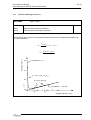
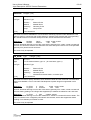
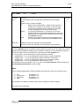
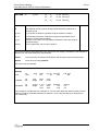
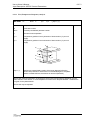
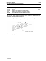
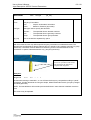
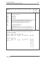
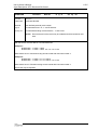
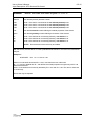
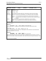
DYNAMIC
End_Time
Delta_T dT_res
dT_term
Parameter
Description
Default
End_Time
Continue the dynamic analysis with the specified time increment to the
specified 'End_Time' is reached.
Delta_T
Time increment to be used until 'End_Time' is reached.
dT_res
Time between saving of results on the 'raf'-file
dT_term
Time between print to terminal
10*D_T
D_T
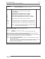
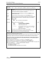
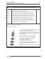
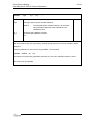
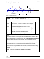
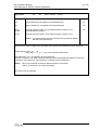
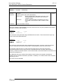
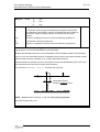
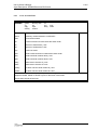
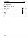
This record is used to specify dynamic analysis with all loading controlled through time.
This record may be repeated.
Example:
DYNAMIC
DYNAMIC
DYNAMIC
0.1
1.0
10.0
0.001
0.010
0.020
0.10
0.50
0.50
0.1
0.1
0.1
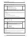
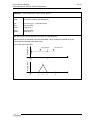
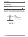
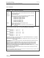
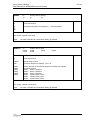
means that the dynamic analysis is started with a time increment of 0.001s which is kept until time =
0.1s is reached. Then the time increment is increased to 0.010s which again is changed to 0.020 at
time 1.0. The analysis will terminate at time = 10.0s.
Terminal print is updated each 0.1'th second, and results are saved each 0.5'th second.
In connection with the DYNAMIC option, the global step counter is updated each time the results are
saved, and the limitation of maximum steps (ref CMAXSTEP record) is affected by the total number of
steps saved only. In the example, the total number of saved steps is 1+2+18=21 (default maximum
steps to be saved is 512).
However, total number of (internal) analysis steps is: 100+90+450 = 640.
Reduced saving of results reduces both the disc space requirements and the cpu time.
∆T1
End-Time 1
∆T2
∆T3
End-Time 2
End-Time 3
Time
2010-01-01
6.3-14
USFOS USER’S MANUAL
Input Description USFOS Control Parameters
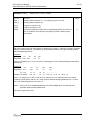
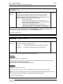
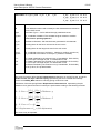
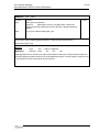
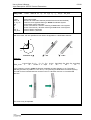
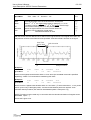
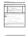
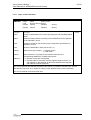
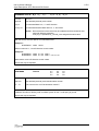
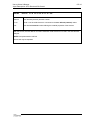
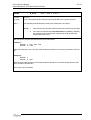
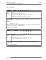
TIMEHIST
histno Points time1 factor1 time2 factor2 ...
Parameter
Description
histno
Time history number (user defined ID)
type
Time Hist Type = 1 (discrete points)
time1
factor1
time (seconds)
Scale factor 1
time2
factor2
time (seconds)
Scale factor 2
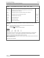
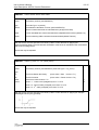
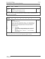
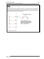
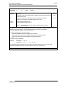
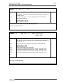
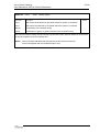
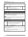
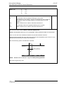
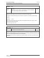
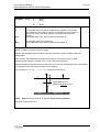
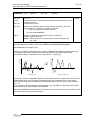
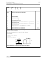
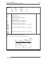
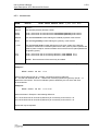
With this record, the user specifies a time history by discrete points.
Values between the tabulated points are interpolated, values outside the specified range are
extrapolated as indicated in the figure below.
Scaling factor
This record may be repeated.
interpolated
3
2
extrapolated
1
Time
t3
Scaling factor
t1 t2
3
1
t1
2
t2
t3
4
5
t4
t5
Time
2010-01-01
6.3-15
USFOS USER’S MANUAL
Input Description USFOS Control Parameters
TIMEHIST
histno Switch dTime factor Tstart
Parameter
Description
histno
Time history number (user defined ID)
type
Time Hist Type = 3 (switch)
dTime
Time between calculation of forces, (see WAVEDATA).
dTime=0 means that loads are calculated every analysis time step.
factor
Forces calculated from wave/current/wind are multiplied with this factor (default=1.0)
Tstart
Time for switching ON the actual environmental load (default Tstart=0)
With this record, the user specifies a time history used to control the time for applying the
wave/current/wing loads. The time between recalclation of the forces is controlled in this command as
well as force scaling factors.
This record may be repeated.
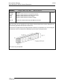
TIMEHIST
histno S_Curve T1 T2 ( factor power)
Parameter
Description
Def
histno
Time history number (user defined ID) Time Hist Type = 4 (s_Curve)
type
T1
Time for activation this history.
(Curve value = Zero
T2
Time for full value .
(Curve value = Factor for time > T2)
factor
Actual curve value for time > T2
1
power
power= 1 : Linear curve (straight line) from T1 to T2
2
for time < T1)
power = 2 : Second order (s-shaped) curve from T1 to T2
power = 3 : 3rd order (s-shaped) curve from T1 to T2
With this record, the user specifies a time history used to control the time for applying for example
deadweight and buoyancy gradually.
This record may be repeated.
2010-01-01
6.3-16
USFOS USER’S MANUAL
Input Description USFOS Control Parameters
TIMEHIST
histno ConstInc dTime Fac1 Fac2
Facn …
Parameter
Description
histno
Time history number (user defined ID)
type
Time Hist Type = ConstInc (type 6)
dTime
The constant time increment between the tabulated values
Fac 1
Fac 2
Scale factor 1
Scale factor 21
Fac n
Scale factor n
With this record, the user specifies a time history by discrete points, where the time between each
point is constant. (This is a special version of the “Points” time history type) and is recommended for
extreme long time series, (reduced memory requirement and faster simulation).
Values between the tabulated points are interpolated, values outside the specified range are
extrapolated..
This record may be repeated.
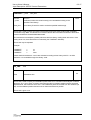
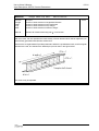
TIMEHIST
histno Sine
Amp Period Phase ( tStart nPer )
Parameter
Description
Def
histno
Time history number (user defined ID) Time Hist
type
Type = 2 (Sine Function)
Amp
Period
fPhase
tStart
nPer
Aplitude
Perod
Phase (degrees)
Start time for sine function. (Function value = 0 for T< tStart)
Number of Periods to apply
0
∞
With this record, the user specifies a time history following a sine function.
Amp
Time
This record may be repeated.
2010-01-01
6.3-17
USFOS USER’S MANUAL
Input Description USFOS Control Parameters
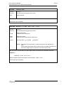
LOADHIST L_Case
Time_Hist
Parameter
Description
Default
L_Case
Loadcase number of the load vector(s) to be activated according to the
specified 'Time History'.
Time_Hist
Time History ID which is used to scale the specified loadvector(s).
This record is used to specify the loads to be activated during a dynamic analysis with all loading
controlled through time. The different time histories defines when the loads connected to these time
histories should be activated/scaled/deactivated.
The loadvectors are multiplied, (scaled) with the actual time history scaling factor at the time. If the
scaling factor is 0, the actual load is not activated, (see 'TIMEHIST' definition).
This record may be repeated.
Example:
LOADHIST
LOADHIST
LOADHIST
1
5
7
10
10
1000
means that both loadvectors 1 and 5 are activated according to time history with ID = 10 while
loadvector 7 is controlled through time history 1000.
INI_TIME
Time
Parameter
Description
Time
Initialization time.
Default
0.0
This record is used to specify an initialisation phase used f ex in connection with analyses of slender
structures. The “USFOS clock” is reset to zero when the time is reached, together with the structural
displacements, which also are set to zero. The initialisation phase is removed from the result file (raf
file), and the initialised position becomes the un-deformed reference position.
.
This record is given once.
2010-01-01
6.3-18
USFOS USER’S MANUAL
Input Description USFOS Control Parameters
6.3.3
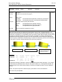
Dynamic Modelling Parameters
alpha1 alpha 2
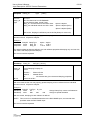
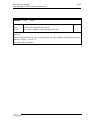
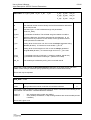
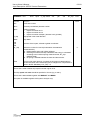
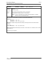
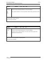
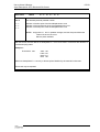
RAYLDAMP
Parameter
Description
Default
alpha1
Mass proportional damping coefficient
alpha2
Stiffness proportional damping coefficient
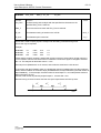
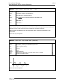
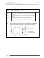
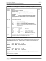
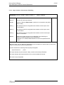
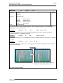
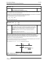
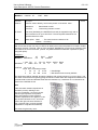
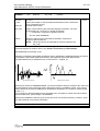
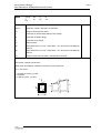
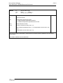
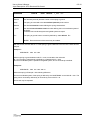
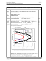
This record is used to control structural damping according to the Rayleigh damping model
If the damping ratio is known for two individual structural frequencies, the damping parameters may
be chosen as follows:
α1 =
2ω 1ω 2
( λ1ω 2 - λ 2 ω 1 )
ω 22 - ω 12
Damping ratio [ l ]
α2 =
0.6
2( ω 2 λ 2 - ω 1 λ 1 )
ω 22 - ω 12
Asymptote: w i = 0
0.4
l i = 1/2 ( a 1 /w i + a 2 w i )
0.2
Specified damping
l2
l1
0.0
0.0
Asymptote: l i = 1/2 a 2 w i
w1
2.0
w2
4.0
6.0
Angular frequency [w ]
2010-01-01
6.3-19
USFOS USER’S MANUAL
Input Description USFOS Control Parameters
DampRatio Ratio_1
Ratio_2 Freq_1 Freq_2 History
Parameter
Description
Default
Ratio_1
Ratio_2
Damping ratio at frequency 1 (1% damping is given as 0.01)
Damping ratio at frequency 2
Freq_1
Freq_2
Frequency 1 (given in Hz)
Frequency 2 (given in Hz)
History
Time history (optional) scaling the actual damping ratios as a function of
time. If omitted (or set equal to 0) the damping is kept constant during
the analysis.
0
With this record the the user may specify the damping to be used in a Dynamic Analysis. Rayleigh
damping coefficients (alpha_1 and alpha_2) are calculated on basis on the given damping ratios
and associated frequencies.
Example 1
'
d1
DampRatio 0.02
d2
0.01
fq1
0.1
fq2
10
means 2% damping at 0.1 Hz (T=10s) and 1% damping at 10 Hz. Constant damping ratios during
the analysis.
Example 2
'
d1
DampRatio 0.01
‘
'
ID Typ
TimeHist 101 points
d2
0.01
t1 f1
0.0 1.0
fq1
0.1
fq2
10
t2
10
Hist
101
f2 …….....................
1.0 11.0 5.0 12 .0 1.0 100.0 1.0
means 1% damping at 0.1 Hz (T=10s) and 1% damping at 10 Hz. Damping ratios are scaled
according to time history with id = 101, which means increased damping between time = 10 and
time = 12. Peak damping is 5% at time=11s.
NOTE ! This record is an extended alternative to the RAYLDAMP input, and override data
specified under the RAYLDAMP input.
This record is given only once.
2010-01-01
6.3-20
USFOS USER’S MANUAL
Input Description USFOS Control Parameters
DampData
Damp_ID
Type
[ Data ]
Parameter
Description
Default
Damp_ID
Type
ID to be referred to from ELEMDAMP
Kind of Damping data. Actual Types:
Rayl_All : Common data for all 6 dofs. Data:
Rayl_Ind: Individual data for the dofs. Data:
alpha1 & alpha2
alpha1 & alpha2 (Dof1)
alpha1 & alpha2 (Dof6)
Alfa1 and 2: Rayleigh Coefficients (see under RaylDamp for more info)
With this record the the user may specify general damping to be be referred to from individual
elements used in a Dynamic Analysis..
Example 1
'
DampID DampType
DampData 10010
Rayl_All .
DampData 10011
Rayl_All .
alpha1 alpha2
0.0
3.0E-4
1.0E-2 3.0E-4
Two damping data packets are defined. One with stiffness proportional damping only and one with
both mass- and stiff proportional damping.
This record could be repeated.
ElemDamp
Damp_ID
ListType [ Id-List ]
Parameter
Description
Damp_ID
ListType
Actual Damping Property ID
Actual
Element :
Element ID list
Material :
Material ID list
All
:
All elements are given the actual damping properties
ID-List
Actual List of ID’s
Default
With this record the the user may specify general damping to be be referred to from individual
elements used in a Dynamic Analysis..
Example 1
'
DampID
ElemDamp 10010
ElemDamp 10011
ListType ID_List
All
Mat
200
300
! Assign Damp Prop 10010 to all elements
! Assign to special thereafter
With this record, damping for each element is defined.
NOTE ! This record is an extended alternative to the RAYLDAMP input, and override data
specified under the RAYLDAMP input.
This record could be repeated.
2010-01-01
USFOS USER’S MANUAL
Input Description USFOS Control Parameters
6.3-21
LUMPMASS rotmas
Parameter
Description
Default
rotmas
Rotational mass scaling factor
0.01
This record is used to prescribe use of a lumped mass formulation for the structural finite element in
connection to dynamic analysis
If rotmas is set to zero the mass terms associated with rotation at the element nodes are zero, ref
USFOS Theory Manual Sect 14
This record is given only once.
CONSIMAS
This record is used to describe use of the consistent mass formulation ref USFOS Theory Manual
Sect 14
This record is given only once.
SYSDAMP
[Switch]
Parameter
Description
switch
Switch ON/OFF:
Switch = 0
Switch = 1
Default
:
:
0
Switch OFF system damping
Switch ON system damping
This record is used to switch ON system damping formulation, (forming a separate C0 matrix). By
default (if Sysdamp is not specified in the input), C0 is not established, and only Rayleigh system
damping is available.
It is recommended to switch Sysdamp ON, if discrete dashpot dampers are defined, (the dashpot
damping terms will be added to C0 matrix on top of the usual Rayleigh coefficients).
This record is given only once.
2010-01-01
6.3-22
USFOS USER’S MANUAL
Input Description USFOS Control Parameters
Ini_Velo
Type
Time
Vx Vy Vz
rVx rVy rVz
Parameter
Description
Type
Data type used to specify initial velocity at nodes:
Id_1
Id_2
.........
Default
Node
:
The specified Id's are node numbers which all should be
assigned to the initial velocity at the specified time.
Mat
:
The specified Id's are material numbers. All nodes "in
contact" with elements with the specified material
numbers will all be assigned to the initial velocity at the
specified time.
Time
Time for the velocity to be initialized
Vx
Vy
Vz
rVx
rVy
rVz
Velocoty X-component
Velocoty Y-componet
etc....
Velocoty component: rotation about X-axis
etc...
Id_1
Id_2
Node number 1 (if Type is Node) or Material no. 1 (if Type is Mat)
Node number 2 (if Type is Node) or Material no. 2 (if Type is Mat)
With this record the the user may specify initial velocity for a Dynamic Analysis..
Example 1 :
'
Typ Time
Ini_Velo Mat 0.0 1.5
Velo
0 0 0 0 0
Mat_ID
1001
will assign a X-velocity of 1.5 m/s to all nodes on the "body" with material ID 1001 from time= 0.0.
Example 2:
'
Typ Time
Ini_Velo Mat 10.0 0 2 0
Velo
0 0 0
Mat_ID
2002
will assign a Y-velocity of 2.0 m/s to all nodes on the "body" with material ID 2002 at time 10
seconds.
This record may be repeated.
2010-01-01
6.3-23
USFOS USER’S MANUAL
Input Description USFOS Control Parameters
Dynres_N
Type
Node_ID
Dof
( Node_2
Dof_2 )
Parameter
Description
Type
Actual Node result type:
Disp
:
Nodal Displacement
Vel
:
Nodal Velocoty
Acc
:
Nodal Acceleration
RelDis :
Relative displacement between 2 nodes/dofs, (extra node
and dof required)
Node_ID
Actual Node ID of which dynamic results should be saved
Dof
Actual Nodal degree of freedom:
1
:
X – displacement
2
:
Y – displacement
etc...
Node_2
Dof_2
Second node (relevant if RelDis only)
Secon node degrees of freedom (relevant if RelDis only)
Default
With this record the the user may specify nodal quantities to be saved every step during a Dynamic
Analysis independent on the 'raf'-file saving interval. Results are stored on a separate file named
<prefix>.dyn, and these time histories are accessed from XACT.
This record may be repeated.
2010-01-01
6.3-24
USFOS USER’S MANUAL
Input Description USFOS Control Parameters
Dynres_E
Type
Elem_ID
End
Dof
( opt )
Parameter
Description
Default
Type
Actual Element result type:
Disp
:
Element Displacement
Force
:
Element Force
Elem_ID
Actual Element ID of which dynamic results should be saved
End
Element end
Dof
Actuall local element degree of freedom:
1
:
X - displacement / Axial force
2
:
Y - displacement / Shear force, y-direction
If the element is a shell element, see description below.
Opt
If the element is a Shell Element, the forces could be projected into the
local coordinate system of a beam element. “Opt” is then the beam
element ID.
0
With this record the the user may specify element quantities to be saved every step during a
Dynamic Analysis independent on the 'raf'-file saving interval. Results are stored on a separate file
named <prefix>.dyn, and these time histories are accessed from XACT.
Dynres forces for Beam Elements always refer to local beam coordinate system.
Dynres forces for Shell Elements could be referred as follows:
'
• Forces are referring to Global Coord system ( default )
• Forces are referring to the Local Beam axix of a reference Beam Element
'
When forces are referring to a Beam, the specified DOF referres to The Beam's Local coordinate
system:
'
Example :
'
DynRes_Elem
Type
Force
elem
100
end
3
Dof
1
(BeamID)
1
! Shell Force Projected on Beam
The force component in the beam X-axis is used. '
Element 'end' means local shell element node.
This record may be repeated.
2010-01-01
USFOS USER’S MANUAL
Input Description USFOS Control Parameters
Dynres_G
6.3-25
Type
Parameter
Description
Type
Actual Global result type:
Wint
Wext
Wplast
Wkin
Wtot
WaveLoad
WaveOVTM
ReacBSH
ReacOVTM
WaveElev
ReacXDir
ReacYDir
ReacZDir
ReacXMom
ReacYMom
Default
:
:
:
:
:
:
:
:
:
:
:
:
:
:
:
Internal Energy
External Energy
Internal Plastic Energy
Kinetic Energy
Total Energy
Total Wave Load Forces
Wave Overturning moment.
Base Shear Reaction.
Reaction Overturning Moment
Surface Elevation
Reaction force. Global X- Direction
Reaction force. Global Y- Direction
Reaction force. Global Z- Direction
Reaction Moment about Global X axis
Reaction Moment about Global Y axis
With this record the user may specify global quantities to be saved every step during a Dynamic
Analysis independent on the 'raf'-file saving interval. Results are stored on a separate file named
<prefix>.dyn, and these time histories are accessed from XACT for time history and frequency
distribution presentation.
This record may be repeated.
2010-01-01
USFOS USER’S MANUAL
Input Description USFOS Control Parameters
6.3.4
6.3-26
Analysis Control Parameters
CPROPAR
epssol gamstp ifunc pereul ktrmax dentsw cmax ifysw detersw
Parameter
Description
Default
epssol
Numerical accuracy of the equation solver (Sect 4.6)
gamstp
Accepted value for overshooting the yield surface (Sect 4.2.2)
0.10
ifunc
FEM beam shape function (Sect 3.1)
1: Sine/cosine shape functions
3: 3rd degree polynomials
2: 3rd degree polynomials used when Px ≤ PEuler*pereul
Sine/cosine functions used when Px > PEuler*pereul
2
pereul
Level of transition from 3rd degree plonomial shape function to
sine/cosine shape function. Specified as a factor of the Euler buckling
load (Sect 3.1)
0.05
ktrmax
Max number recalculations of one load step due to element unloading
(Sect 4.1)
5
dentsw
Formulation of dented tubes and local buckling (Sect 3.4)
0: Only initially perfect cross section included
1: Local damages and dent growth included for tubes. Local buckling
of initially perfect rectangular and tube cross section included
1
cmax
Elastic spring-back is introduced when the current Stiffness Parameter
exceeds cmax (Sect 4.2.1)
999
ifysw
Parameter for elasto-plastic transition
0: Elasto-plastic transition performed
1: Elasto-plastic transition not performed
0
detersw
Determinant criterion for identification of load limit points or bifurcation
points
0: No determinant check
1: Determinant criterion active. Load increment is reversed when the
determinant changes sign
1
1.0E-20
This record may be used to change default program parameters
This record is given only once
2010-01-01
USFOS USER’S MANUAL
Input Description USFOS Control Parameters
6.3-27
SURF2OFF
Parameter
Description
Default
Switch off two-surface model, (Elasto-plastic transition not performed)
This record overrides default data and data specified on CPROPAR
record
ARC_OFF
Parameter
Description
Default
Switch off arc length control.
This record overrides default data and data specified on CPROPAR
record
DETEROFF
Parameter
Description
Default
Switch off determinant check.
This record overrides default data and data specified on CPROPAR
record
DENT_OFF
Parameter
Description
Default
Switch off formulation of dented tubes and local buckling.
This record overrides default data and data specified on CPROPAR
record
2010-01-01
USFOS USER’S MANUAL
Input Description USFOS Control Parameters
6.3-28
Type
DENT_TYPE
Parameter
Description
Default
Type
Dent formulation type. 0
:
Default dent formulation
0
Cyclic dent formulation
This record may be used to switch on the cyclic dent formulation.
This record is given once
CMAXSTEP Max_step
Parameter
Description
Default
Max_step
Max number of steps
512
This record may be used to increase the max number of analysis steps availabe.
This record is given once.
EIGENVAL KeyWord Value
Parameter
Description
Keyword
Keyword describing the actual “Value”:
Time
NumberOf
ModeScale
Algorithm
Shift
Value
Default
: Definition of the time when the eigenval is performed.
: Specification of nuber of eigenvector to compute.
: Scaling of eigenvectors in connection with visualization.
: Actual algoritm to use. (SubSpace or Lanczos)
: Shift parameter used if singular systems.
20
1.0
SSIT
0.0
Actual value
This record is used to perform an eigenvalue analysis for calculation of vibration frequencies and
corresponding modes, (Ref: EigenSolvers for structural problems by K.Bell). The
eigenvalues/modes are calculated, and the mode-shapes may be inspected in XACT. If the modes
are difficult to see (small displacements), specify the modescale, f ex wit ha value=10.
NOTE ! Specification of time is important. In order to get correct stresses (and thus correct
nonlinear stiffness), the eigenvalue calculations should be performed when the selfweigth
etc is introduced in the structure.
Available for DYNAMIC analysis only
This record could be repeated.
2010-01-01
USFOS USER’S MANUAL
Input Description USFOS Control Parameters
CBIFURC
6.3-29
idcomb idstep ibifsw
Parameter
Description
idcomb
Load combination to be reached before the bifurcation analysis
becomes active
idstep
Load step to be reached before the bifurcation analysis becomes active
ibifsw
= 0 or <blank>:
Default
0
Eigenvectors and eigenvalues are calculated and written to the print file
at the loadstep where bifurcation is detected.
The .bif file is generated with nodal loads corresponding to the
eigenvectors
= 1:
In addition the eigenvectors are written to the result file for XACT
presentation and the analysis is then terminated. Each eigenvector is
stored as global displacements for dummy load steps which follow the
last real loadstep in consecutive order
This record may be used switch on the bifurcation analysis
2010-01-01
6.3-30
USFOS USER’S MANUAL
Input Description USFOS Control Parameters
6.3.5
Numerical Procedure Parameters
CITER
cmin cneg itmax isol epsit cmineg
Parameter
Description
Default
cmin
Iterations omitted for current stiffness value between cmin and cmineg
0.000
cneg
Definition of "large" negative current stiffness
itmax
Max number of iterations
10
isol
Number of iterations between updating of stiffness matrix
1
epsit
Convergence criterion for iterations
cmineg
Iterations are omitted for current stiffness value between cmin and
cmineg
-2.0
0.0001
-cmin
This record may be used to switch on iteration, and to change default program parameters
Note!
Iterations should not be performed if the SHELL option is activated.
This record is given once
LITER
[itmax]
Parameter
Description
itmax
Max number of iterations
Default
1
This record may be used to switch on “Light” iteration, with possibility to change the itmax only.
The other parameters are fixed, (“CITER” default parameters, see above).
Note!
Iterations should not be performed if the SHELL option is activated.
This record is given once, and if CITER is specified (before LITER), these parameters are kept,
(except itmax).
CUNFAL max on/off
Parameter
Description
max on/off
Max number of subsequent load steps with plastification/elastic
unloading of a single element
Default
This record impose restrictions on repeated plastification/elastic unloading of single elements
If an element unloads/re-plastifies in more than max on/off subsequent load steps, elastic
unloading will be suppressed in the remaining steps
The restriction is removed the first time the element goes through a load step without trying to
unload. The restriction is also removed on the first load step of each new load vector (Sect 4.2),
e.g. if the external load is reversed
This record is given only once
2010-01-01
6.3-31
USFOS USER’S MANUAL
Input Description USFOS Control Parameters
CDYNPAR
alpha beta gamma
Parameter
Description
Default
alpha
Integration parameter controlling high frequency numerical damping
beta
Newmark integration parameter
0.25
gamma
Newmark integration parameter
0.50
0
To obtain high frequency numerical damping, select alpha in the range 0.3 to 0.0. The accuracy in the integration of the equation of motion is
maintained for this case by setting both beta and gamma negative.
USFOS will then automatically select the Newmark integration
parameters to:
γ = 1/2(1-2α)
ß = 1/4(1-α)2
-0.3 ≤ α ≤ 0.0
This record may be used to specify numerical integration parameters for the time integration of the
equation of motion according to the Hilber Hughes and Taylor alpha-dissipation method, ref USFOS
Theory Manual, Sect 14
PCOR_ON
Parameter
Description
Default
Predictor-Corrector approach used in the numerical integration of the
equation of motion. The solution of the equation of motion at a typical
time-step is then performed as a two-step procedure:
1.
2.
Predict increments in velocity and acceleration
Perform corrector steps. One or several corrector steps may be
specified on the CITER record
This record may be used to activate the Predictor-Corrector approach in the numerical time
integration of the equation of motion
Note!
This record may only be used in combination with the CITER record
PCOR_OFF
Parameter
Description
Default
Predictor-Corrector approach NOT used when solving the equation of
motion by means of numerical integration.
2010-01-01
6.3-32
USFOS USER’S MANUAL
Input Description USFOS Control Parameters
6.3.6
Material/Plasticity Modelling
MISOIEP
matno
c1
c4
E-mod poiss
a1
c2
a4
c5
yield
a2
a5
density term.exp
c3
a3
c6
a6
Parameter
Description
matno
Material reference number
E-mod
Elastic modulus
poiss
Poisson's ratio
yield
Yield strength
density
Mass density
term.exp
Thermal expansion ratio
c1
a1
c2
a2
.
.
.
c6
a6
Hardening parameter for x-force
Elasto-plastic growth parameter for x-force
Hardening parameter for y-force
Elasto-plastic growth parameter for y-force
Default
2.0⋅10-3
0.25
2.0⋅10-3
0.25
Ditto for z-force
x-moment
y-moment
z-moment
This record is used to specify material properties when USFOS is used as a stand alone program
or if the "host" analysis system does not supply all parameters (i.e. yield strength), or if hardening
properties will be changed
The default hardening properties refer to the condition where elasto-plastic transition is performed,
see record CPROPAR. If elasto-plastic transition is not performed, the default values are zero
c2-c6 are not given if they are equal to c1
a2-a6 are not given if they are equal to a1
This record may be repeated
2010-01-01
6.3-33
USFOS USER’S MANUAL
Input Description USFOS Control Parameters
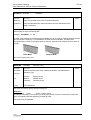
GBOUND
geono
zym
zbm
Parameter
Description
geono
Geometry number
m
zyc
zbc
Default
zy
Extension ("size") of the yield surface, relative to the bounding surface
(Sect 4.3.2). Material behaviour under monotonous loading
zbm
Extension ("size") of the bounding surface ("full plastic capacity")
(Sect 4.3.3). Material behaviour under monotonous loading
zyc
Extension of the "cyclic" yield surface, relative to the "cyclic" bounding
surface. (Material behaviour under cyclic loading)
zbc
Extension of the "cyclic" bounding surface. (Material behaviour under
cyclic loading)
This record is mandatory for general beams. For other cross sections it may be used to change
default values
Default z-yield values are determined by the ratio of elastic and plastic section modulus of typical
cross sections
I or H:
Box:
Pipe:
def =
def =
def =
zym
0.87
0.83
0.79
zbm
1.0
1.0
1.0
zyc
0.65
0.65
0.60
zbc
1.00
1.00
1.00
The record is only relevant if elasto-plastic transitation is performed, see record CPROPAR
2010-01-01
6.3-34
USFOS USER’S MANUAL
Input Description USFOS Control Parameters
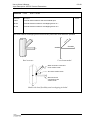
MREF
matno
refx
refy
refz
refrx
refry
refrz
Parameter
Description
matno
Material number
refx
Properties in local x-direction is defined by material with ID number refx
refy-refrz
Similar to refx for the other degrees of freedom
Default
This record is used to specify material properties for the nonlinear spring element (both 1 node
and 2 node)
This record may be repeated
Properties in the 6 DOF's are specified by referring to other material input (SESAM record MISOPL
or UFO records HYPELAST and ELPLCURV). Material numbers equal to zero means that the
spring has no stiffness in the actual degrees of freedom
If element type no 18 (spring to ground) refers to a "MREF" material, the element will be handled by
USFOS as a 1 node nonlinear spring to ground
If element type no 15 (2 node beam), refers to a "MREF" material, the element will be handled by
USFOS as a 2 node nonlinear spring
2010-01-01
6.3-35
USFOS USER’S MANUAL
Input Description USFOS Control Parameters
MPLASMON matno
c1
c4
a1
a4
c2
c5
a2
a5
c3
c6
Parameter
Description
matno
Material reference number
c1
a1
c2
a2
.
.c6
a6
Hardening parameter for x-force
Elasto-plastic transition parameter for x-force
Hardening parameter for y-force
Elasto-plastic transition parameter for y-force
a3
a6
Default
2.0⋅10-3
0.25
2.0⋅10-3
0.25
Ditto for z-force
x-moment
y-moment
z-moment
This record is used to specify material hardening parameters and elasto-plastic transition
parameters for the material under monotonous loading conditions
The default hardening properties refer to the condition where elasto-plastic transition is performed,
see record CPROPAR. If elasto-plastic transition is not performed, the default values are zero
c2-c6 need not be given if they are equal to c1
a2-a6 need not be given if they are equal to a1
Below, and example describes the “a”-parameter’s impact on the stress-strain curve. ((Typical Steel
material with E=210.000Mpa and Yield=355Mpa). The hardeing is fixed to 0.2% in the example.
Rigid
Medium
Soft
UltraSoft
(Green curve)
(Red curve)
(Blue Curve)
(Pink curve)
a = 2.0
a = 1.0
a = 0.25 (Default)
a = 0.15
This record may be repeated
2010-01-01
6.3-36
USFOS USER’S MANUAL
Input Description USFOS Control Parameters
MPLASCYC matno
c1
c4
a1
a4
c2
c5
a2
a5
c3
c6
Parameter
Description
matno
Material reference number
c1
a1
c2
a2
.
.
.
c6
a6
Hardening parameter for x-force
Elasto-plastic growth parameter for x-force
Hardening parameter for y-force
Elasto-plastic growth parameter for y-force
a3
a6
Default
0.014
0.84
0.024
0.34
Ditto for z-force
x-moment
y-moment
z-moment
This record is used to specify material hardening parameters and elasto-plastic transition
parameters for the material under cyclic loading conditions
The default hardening properties refer to the condition where elasto-plastic transition is performed,
see record CPROPAR. If elasto-plastic transition is not performed, the default values are zero
c2-c6 need not be given if they are equal to c1
a2-a6 need not be given if they are equal to a1
This record may be repeated
2010-01-01
6.3-37
USFOS USER’S MANUAL
Input Description USFOS Control Parameters
6.3.7
Member Modelling
CELHINX
elnox
ihin1
ihin2
ihinmid
Parameter
Description
Default
elnox
External (user-specified) element number
ihin1
Restriction code for plastic hinge development at first node
0: Plastic hinge free to develop
1: Plastic hinge is suppressed
ihin2
Restriction code for plastic hinge development at second node
ihinmid
Restriction code for plastic hinge development at midspan
This record may be used to suppress development of plastic hinges on specified elements
(Sect 4.5)
This record may be repeated
ihin1
PLASTHIN
ihin2
ihinmid
elnox1
elnox2
Parameter
Description
ihin1
Restriction code for plastic hinge development at first node
0:
1:
...
Default
Plastic hinge free to develop
Plastic hinge is suppressed
ihin2
Restriction code for plastic hinge development at second node
ihinmid
Restriction code for plastic hinge development at midspan
elnox1
elnox2
.
.
External (user-specified) element number 1
External (user-specified) element number 2
.
.
NOTE ! If no elements are specified, all beam elements get the actual
restriction code.
This record may be used to suppress development of plastic hinges on specified elements.
This record may be repeated
Example:
PLASTHIN
PLASTHIN
0 0 1
0 0 0
1010 1020 1030
Will suppress plastic hinge at midspan for all elements except for elements 1010, 1020 and 1030.
This record is an alternative to the *CELHINX* record.
2010-01-01
USFOS USER’S MANUAL
Input Description USFOS Control Parameters
ix1 iy1 iz1 irx1 iry1 irz1
ix2 iy2 iz2 irx2 iry2 irz2 elnox1 elnox2 .... elnoxn
BEAMHING
Parameter
Description
ix1
Fixation Code for Local X-Direction of node 1 of element :
0 : Fully Released
1 : Fully Connected
Fixation Code for Local Y-Direction of node 1 of element
Fixation Code for Local Z-Direction of node 1 of element
Fixation Code for Torsion Moment of node 1 of element
Fixation Code for Moment about Local Y-axis of node 1 of element
Fixation Code for Moment about Local Z-axis of node 1 of element
iy1
iz1
irx1
iry1
irz1
ix2
elnox1
elnox2
.
.
elnoxn
6.3-38
Default
Fixation Code for Local X-Direction of node 2 of element
etc...
External element number 1 to be defined with the actual internal hinge
External element number 2 to be defined with the actual internal hinge .
.
External element number n to be defined with the actual internal hinge
NOTE ! If no elements are specified, all beam elements will be defined
with the actual internal hinge definition.
This record is used to assign internal hinges to beam elements.
This record may be repeated.
Example:
BEAMHING 1 1 1 1 0 0 1 1 1 1 0 0
BEAMHING 1 1 1 1 1 1 1 1 1 1 1 1 1010 1020 1030 2010 2020 2030
Default internal hinge is changed from fully connected( default) to released bending degrees of
freedom at both ends of the elements, (applied to all beam elements).
However, elements 1010 1020 1030 2010 2020 and 2030 are defined with fully connected joints at
both ends, (the latest BEAMHING definition overrides previous definitions).
NOTE ! This option should be used with care!
Due to nonlinear geometrical effects, the release of some degrees of freedom could be
valid at the first step only.
This is obvious in connection with release of the two shear degrees of freedom (no 2 and
3) where the vertical component of the axial stiffness will become more and more
significant as the beam axis rotates.
2010-01-01
6.3-39
USFOS USER’S MANUAL
Input Description USFOS Control Parameters
impgroup impshape
GIMPER
angle
offset
dent1
Parameter
Description
impgroup
Reference number of imperfection group
impshape
Shape of initial deformation (Sine-functions)
0:
1:
2:
angle
dent2
dentmid
Default
Both ends rotated
End 1 undeformed
End 2 undeformed
Orientation of offset and dent. Specified in degrees counter-clockwise
from the local element z-axis
z
x
z
y
of
fs
M
z
et
q
dent
y
y
M
Section M-M
offset
Maximum offset divided by element length
dent1
Depth of dent divided by pipe diameter. First node
dent2
Depth of dent divided by pipe diameter. Second node
dentmid
Depth of dent divided by pipe diameter. Element midspan
This record is used to define initial deformations and damage conditions for tubes (Sect 3.4)
Note!
The effect of local dents is only included if the dent switch parameter dentsw = 1 (default)
(Sect 6.3.C)
This record may be repeated
2010-01-01
6.3-40
USFOS USER’S MANUAL
Input Description USFOS Control Parameters
GELIMP
elnox
impgroup
Parameter
Description
Default
elnox
External (user-defined) element number
impgroup
Reference number of imperfection group
This record is used to assign initial deformations or damage conditions to specified elements
This record may be repeated
BLINDP2
insl
iem
ix
iy
iz
irx
iry
irz
Parameter
Description
insl
Slave (dependent) node
iem
Element with master (independent) node(s). The coupled degrees of
freedom (DOFs) are referred to this local element coordinate system
ix
iy
iz
irx
iry
irz
Specification of linear dependent DOFs in local master element
coordinate system:
i.. = 0
i.. = 1
i.. = -1
Default
No coupling
The slave DOF is linearly dependent on the corresponding
master DOF(s) (including torsional effects for iy and iz,
Ref. /1/)
Only valid for iy and iz. Same as i.. = 1, but not including
torsional effects
This record is used to define dependent degrees of freedom (Sect 3.8)
The record is given once for every node with dependent degrees of freedom
2010-01-01
6.3-41
USFOS USER’S MANUAL
Input Description USFOS Control Parameters
NONSTRU
ListType { List }
Parameter
Description
ListType
Definition Type:
Element :
Material :
Geometry:
Group :
Visible :
{ List }
Default
Element ID list
Material ID list
Geometry ID list
Group ID list
The nonstructural elements are visualized in Xact,
(default invisible)
List of actual ID’s
This record is used to specify non structural beam elements (passive elements), and such elements
are excluded from the global stiffness formulation while the elements’ attracted loads are kept.
Example 1:
NonStru
NonStru
Element
Geom
1001 1002 2001 2002
27304 27305 27306
All beam elements referring to one of the cross section geometry ID’s: 27304, 27305 or 27306 will
become non structural. In addition, the elements 1001, 1002, 2001 and 2002 get “nonstru”.
Example 2:
NonStru
Mat
210355 210345
All beam elements referring to one of the material ID’s: 210355 or 210345 will become non
structural.
Example 3:
NonStru
Group
1111 2222 3333
All beam elements “member of” one of the Group ID’s: 1111, 2222 or 3333 will become non
structural.
Example 4:
NonStru
Visible
This command switches ON the visualization of the non structural members. By default, only
structural members are visulaized in Xact.
All parameters may be abbreviated, but enough characters to ensure non ambiguous definition is
required, (Geometry could be specified as Ge, Geo, Geom, etc, material as M, Ma, Mat, etc).
NOTE:
The command: “STRUCTEL” (structural elements) will override the NonStru definitions.
This record may be repeated
2010-01-01
USFOS USER’S MANUAL
Input Description USFOS Control Parameters
STRUCTEL
ListType { List }
Parameter
Description
ListType
Definition Type:
Default
Element :
Material :
Geometry:
Group :
{ List }
6.3-42
Element ID list
Material ID list
Geometry ID list
Group ID list
List of actual ID’s
This record is used to override non structural beam element(s) specified under NONSTRU. This
option is useful in connection with models where for example most elements with given geometry
ID’s should become non structural except some few, which should become structural.
NonStru
Geom
27304 27305 27306
StructEl
Element
1001 1002
All beam elements referring to one of the cross section geometry ID’s: 27304, 27305 or 27306 will
become non structural. However, the elements 1001 and 1002 (which refer to one of the specified
geometry ID’s) should remain structural.
Example 1:
This record may be repeated
LIN_ELEM
Type
ListType { List }
Parameter
Description
Type
For conventional beam, type = 0. (for riser beam, type=1).
ListType
Definition Type:
Element :
Material :
Geometry:
All
:
{ List }
Default
Element ID list
Material ID list
Geometry ID list
All elements become elastic, no further input
List of actual ID’s
This record is used to specify elements, which should be linear and the command is an alternative
to the more detailed PLASTHIN command. Development of plastic hinges is suppressed in all 3
nodes.
Lin_Elem
0
Geom
27304 27305 27306
Lin_Elem
0
Element
1001 1002
All beam elements referring to one of the cross section geometry ID’s: 27304, 27305 or 27306 will
become elastic (yielding in all 3 hinges are suppressed) in addition the elements 1001 and 1002.
Example 1:
Example 2:
Lin_Elem
1
Mat
210355 210345
All beam elements referring to one of the material ID’s: 210355 or 210345 will become elastic. The
beam formulation is the “integration point based” riser element, which also suppresses elastic
buckling if one element per member is used.
This record may be repeated
2010-01-01
6.3-43
USFOS USER’S MANUAL
Input Description USFOS Control Parameters
Size/ColumnCurve
CINIDEF
Pattern
LoadCase
Parameter
Description
Default
Size
Magnitude of initial imperfection or column curve number
Size < 0.1
Size > 1
:
:
e/L given directly
Column curve number
Pat
0
1
2
:
:
:
Use program default (=1)
Direction following member line load
Direction following global base shear
LoadCase
Load case to determine direction of initial imperfection
This record is used to switch on automatic calculation of initial member imperfection for calibration
of analysis model to buckling curves.
Implemented column curves are:
Number
10
15
20
30
41
42
43
44
45
51
52
53
54
55
61
62
63
66
67
68
70
Curve
API WSD / SSRC WSD
draft ISO / NORSOK
AISC
API LRFD
ECCS / NS / NPD Curve A
ECCS / NS / NPD Curve B
ECCS / NS / NPD Curve C
ECCS / NS / NPD Curve A0
ECCS / NS / NPD Curve E
DNV Curve A
DNV Curve B
DNV Curve C
DNV Curve A0
DNV Curve E
SSRC / CSA Curve 1
SSRC / CSA Curve 2
SSRC / CSA Curve 3
SSRC mean column curve 1
SSRC mean column curve 2
SSRC mean column curve 3
Chen column curve
(Lehigh characteristic curve 1)
(Lehigh characteristic curve 2)
(Lehigh characteristic curve 3)
(Lehigh mean curve 1)
(Lehigh mean curve 2)
(Lehigh mean curve 3)
Example
CINIDEF
10
1
3
Means that initial imperfections are assigned on all tubular members according to API WSD column
curve, in direction of the distributed loading for each member under load case 3.
This record is given only once.
2010-01-01
6.3-44
USFOS USER’S MANUAL
Input Description USFOS Control Parameters
BuckMode
Mode No
ScaleFact
Parameter
Description
Default
Mode No
Apply the specified eigen mode as initial imperfection
ScaleFact
Scale the selected eigen values and add to the user defined structural
nodal coordinates.
This record is used to apply initial imperfections based on an eigen value analysis performed
automatically as a pre processing task.
Example : BuckMode
5
0.1
An eigen value analysis automatically will be initiated prior to the ordinary collapse analysis, and the
5’th eigenmode is scaled by 0.1 and added to the initial nodal coordinates. The stress free
structural shape is shown in the figure below (to the left), while the final collapse mode is shown to
the right.
Initial Mode
Collapse Mode
This record is given only once.
GROUTED
GroutMat
ListType { List }
Parameter
Description
GroutMat
Material ID defining the Grout material parameters. (see MATERIAL)
ListType
Definition Type:
List
Element :
Material :
Geometry:
{ List }
List of actual ID’s
Default
Element ID list
Material ID list
Geometry ID list
This record is used to specify elements with grout.
Example 1:
Grouted 1020
Geom
27304 27305 27306
All elements referring to cross section (must be pipes) 27304, 27305 or 27306 will be “filled” with
grout wit material properties defined by material ID 1020
This record may be repeated
2010-01-01
6.3-45
USFOS USER’S MANUAL
Input Description USFOS Control Parameters
ElmTrans
Node ListType ID’s
Type
Unit
Type
Node Reference Type:
□ GlobNode
: “Node” refers to Node ID
□ LocNode
: “Node” refers to the element’s local node (end)
Node
Id of node or local element node (see above).
ListType
Keyword for interpreting of the succeeding ID- list
□ “elem” Element ID’s are specified
□ “Mat”
Material ID’s are listed. Elements referring to mat are
selected
ID’s
Actual ID list
[Deg]
With this record, the user defines how to define and update an element’s local-global transformation
matrix. This command is needed when zero length non linear springs are defined, since the
orientation of the local coordinate system cannot be defined in the normal way. (having local x-axis
going from end 1 to 2 etc).
Example1:
‘
ElmTrans
Type
GlobNode
NodeID
101
ListType
Elem
ID’s
12
Element no 12 will then update it’s transformation according to rotations of node 101.
If Element 12 is a 2-node non linear spring, with ~zero length, (less than 1mm), the following will be
done in addition:
□
The initial local-global transformation matrix will be set equal to the transformation matrix of
the first beam element connected to node 101.
This option is typically used in connection with modelling of bearings, where the properties should
follow the structure’s large displacements and rotations.
100
21
101
22
102
12
2010-01-01
USFOS USER’S MANUAL
Input Description USFOS Control Parameters
Example2:
‘
ElmTrans
Type
LocNode
End
1
ListType
Mat
6.3-46
ID’s
3 5 8
Means that all spring elements referring to materials 3, 5 or 8 will have the local coordinate system
defined by the beam element attached to end 1 of the spring in question. If the user is planning the
modelling of Zero length spring, the amount of input to define the local coordinate system could be
limited to just one line as described in this example.
This record could be repeated..
2010-01-01
6.3-47
USFOS USER’S MANUAL
Input Description USFOS Control Parameters
6.3.8
Joint Modelling
SHELL
nodex
elnox1 elnox2
d
t
Parameter
Description
Default
nodex
External node number referring to the joint where shell effects should be
considered
elnox1
External element number defining one of the two elements connected to
the node
elnox2
External element number defining the second chord element
d,t
Diameter and thickness of the chord at the joint, respectively (canned
joint). If omitted, the data for elnox1 is used
With this record, a complete shell analysis of the specified tubular joint will be included in the
analysis.
Note!
Internally in USFOS one extra element and extra nodes are introduced into the finite
element model, and the CPU consumption of the analysis increases somewhat.
Beam
Beam
Two extra nodes
One extra element
(shell property element)
Beam
Beam
2010-01-01
6.3-48
USFOS USER’S MANUAL
Input Description USFOS Control Parameters
OVERLAP
nodex
elnob1 elnob2 . . . . .
Parameter
Description
Default
nodex
External node number for the actual tubular joint
elnob1
External element number for overlapping brace no 1
elnob2
.
.
.
External element number for overlapping brace no 2
.
.
.
This record defines overlapping braces at the tubular joints where shell effects are specified
O
N
EL
NODEX
Real structure
B1
ELNOB2
Users beam model
Beam eccentric connected
to the surface node
One extra surface node
Beam eccentric
connected to the
surface node
Model with local flexibility and overlapping included
2010-01-01
6.3-49
USFOS USER’S MANUAL
Input Description USFOS Control Parameters
CHJOINT
nodex
Parameter
Description
nodex
External node number referring to the joint where shell effects should be
considered
elnox1
External element number defining one of the two elements connected to
the node
elnox2
External element number defining the second CHORD element
geono
Geometry reference number defining the diameter and thickness of the
chord at the joint (canned joint). If omitted or equal to 0, the data for
elnox1 is used.
Capacity rule switch:
irule = -1 : API (no more data required)
irule = -2 : DoE (no more data required)
irule = -3 : User defined capacity and surface definition, more data
required, (see next pages).
irule = MSL : MSL non-linear joint characteristics, (see next pages).
Irule = -101 : User defined Joint Springs, more data required, (see next
pages).
irule
elnox1
elnox2
geono
irule
Default
With this record, the capacity of each brace/chord connection at the tubular joint will be checked
according to a selected joint capacity equation.
This check will impose restrictions on the load transfer through each brace/chord connection at the
specified joint
By default the extra elements representing the connection capacities are general beam elements.
From version 7.4 it is possible to switch to Joint Springs using the record:
JNT_FORM 1
P_d curves are then derived from the actual capacities as follows:
Displacement = 0.1% of Chord diameter defines 'yielding' (confer JSURFSIZ)
Displacement = 1.0% of Chord diameter defines maximum force/moment
Displacement = 5.0% of Chord diameter defines end of maximum capacity
Displacement = 10 % of Chord diameter defines fracture of joint
The generated curves are printed in the '.out' - file, and the peak capacities will be printed using
the Verify/Element/Information option in Xact.
Beam
Beam
Two extra nodes
Two extra
elements
Beam
Beam
Conventional joint model
Joint with capacity check included
2010-01-01
6.3-50
USFOS USER’S MANUAL
Input Description USFOS Control Parameters
CHJOINT
nodex
elnox1 elnox2 geono rule
nbraces
brace1 Mref_ID1
brace2 Mref_ID2
bracen Mref_IDn
Parameter
Description
nodex
External node number referring to the joint where shell effects should be
considered
elnox1
External element number defining one of the two elements connected to
the node
elnox2
External element number defining the second CHORD element
geono
When user defined capacity is used, this parameter is dummy, but a
dummy parameter must be given
rule
Capacity rule switch = -101, User defined Joint Springs.
nbraces
Number of Braces connected to the actual joint
brace1
Brace element ID of first brace
Mref_ID1
ID of MREF-record defining the nonlinear spring properties of brace 1
connection.
Default
Data for all braces connected to the joint are required !
With this record, the capacity of each brace/chord connection of the tubular joint will be limited by
the user defined P_d curves defining the behaviour of the joint.
This check will impose restrictions on the load transfer through each brace/chord connection at the
specified joint
2010-01-01
6.3-51
USFOS USER’S MANUAL
Input Description USFOS Control Parameters
CHJOINT
nodex
alpha1
nbraces
brace1
......
elnox1 elnox2 geono rule
alpha2 alpha3 alpha4 alpha5
axial
torsion Mipb
Mopb
Parameter
Description
Default
nodex
External node number referring to the joint where shell effects should be
considered
elnox1
External element number defining one of the two elements connected to
the node
elnox2
External element number defining the second CHORD element
geono
Dummy when rule = -3
rule
Capacity rule switch=-3 : User defined capacity and surface definition.
alpha1-5
Parameters used to define the actual surface
nbraces
Number of braces connected to the actual joint
brace1
User defined element number of first brace element
axial
torsion
Mipb
Mopb
Axial capacity:
Torsion capacity:
In plane bending capacity:
Out of plane bending capacity:
brace1 - chord connection
brace1 - chord connection
brace1 - chord connection
brace1 - chord connection
Data for all braces connected to the joint are required
With this record, the capacity of each brace/chord connection at the tubular joint will be checked
according to the specified rule
This check will impose restrictions on the load transfer through each brace/chord connection at the
specified joint
When the USER-defined capacity is used (rule = -3), the following surface definition is applied:
P
Mj
Mj
α5
α1
⎛ ⎛ M z ⎞α 2 ⎛ M i ⎞α 3 ⎛ M 0 ⎞α 4 ⎞
⎛ P ⎞
⎟ +⎜
⎟ +⎜
⎟ ⎟ =1
⎜
⎟ +⎜⎜
⎜
P
M
M
M
M
xu
iu
ou
⎝
⎠
⎠
⎝
⎠
⎝
⎠ ⎟⎠
⎝⎝
2010-01-01
USFOS USER’S MANUAL
Input Description USFOS Control Parameters
CHJOINT
nodex
6.3-52
elnox1 elnox2 geono CapRule CapLevel Qf_SafetyCoeff
Parameter
Description
nodex
External node number referring to the joint where joint capacity and
non-linear joint behaviour should be considered
elnox1
External element number defining one of the two CHORD elements
connected to the node
elnox2
External element number defining the second CHORD element
geono
Geometry reference number defining the diameter and thickness of the
chord at the joint (canned joint). If omitted or equal to 0, the data for
elnox1 is used.
CapRule
Capacity rule:
MSL: MSL non-linear joint characteristics
CapLevel
Capacity level or capacity multiplier.
mean
: use mean value joint capacities
char
: use characteristic joint capacities
fcrack
: use the “first crack” curve
scalfact
Default
:
mean
joint capacities are set to mean value capacities
multiplied by scalfact, (where “scalfact“ is a
positive real number).
This option is only available with the MSL joint formulation.
Qf_Safety
Coeff
The Qf factor for joint capacities includes a safety factor (or partial
safety coefficient) in the chord stress utilisation factor.
1.0
With this record, the capacity of each brace/chord connection at the tubular joint will be checked
according to a selected joint capacity equation
This check will impose restrictions on the load transfer through each brace/chord connection at the
specified joint, and the non-linear joint characteristics will be included in the USFOS analysis.
Extra elements will be introduced in the FE model, and the behaviour of these elements assigned
according to the selected joint capacity rule or specified joint capacity, and the FE formulation
selected for the “joint elements”.
The joint capacity rule or joint capacity is specified by the CHJOINT record(s).
The FE formulation for the “joint elements” is selected by the JNT_FORM record.
Note that use of the MSL formulation is confidential under the contract of the MSL JIP project “Nonlinear joint modelling for ….”. Access to this formulation is limited to
- participants of the MSL JIP project
- their affiliated companies
- other parties acting under authorisation from the above
2010-01-01
6.3-53
USFOS USER’S MANUAL
Input Description USFOS Control Parameters
JSURFSIZ
zym
zbm
nodex1
nodex2
....
Parameter
Description
zym
Default
Extension ("size") of the yield surface, relative to the reference bounding
surface (Sect 4.3.2).
0.50
zbm
Extension ("size") of the bounding surface ("full plastic capacity")
relative to the reference bounding surface (Sect 4.3.3).
1.00
nodex1
nodex2
.
.
External node number of joint 1
External node number of joint 2
.
.NOTE ! If no nodes are specified, all joints defined get the actual
surface ratios.
With this record the user may change the default values of the ratio of elastic and plastic "section"
modulus of the joint model. It is then possible to scale the actual joint capacities,
(f.inst. calculated according to API, see CHJOINT).
This is an useful option in connection with:
Sensitivity studies where joint capacities are important
Cases where some joints are damaged (reducing the bounding surface)
Cases with reinforces joints (expanding the bounding surface)
etc...
This record may be repeated.
Example:
JSURFSIZ
JSURFSIZ
0.95 1.5
0.50 1.0
101 102 103
will change the yield surface size to 0.95 and the bounding surface size to 1.5 of the initial,
reference bounding surface for all joints except for nodes 101, 102 and 103.
2010-01-01
6.3-54
USFOS USER’S MANUAL
Input Description USFOS Control Parameters
JOINTGAP Gap
NodeID
Brace1
Brace2
……
Parameter
Description
Default
Gap
Actual Gap specified in current length unit
NodeID
Brace_i
.
.
Actual Joint, (CHJOINT must be specified for this joint)
The actual gap should be applied to the Braces (Elem ID’s) specified.
NOTE 1: If no node is specified, all joints defined get the actual gap.
NOTE 2: If no braces are specified, all braces get the actual gap.
With this record the user may override the gaps between braces, which are computed based on the
structural model, (member coordinates and offsets).
This is a useful option if the structural model does not describe correct gaps (f ex a model without
member eccentricities/offsets).
This record may be repeated.
Example 1:
‘
JOINTGAP
Gap
0.050
(NodID)
This will force a gap = 0.050 to be used in all relevant capacity calculations for all joints with
CHJOINT applied (does not influence T/Y capacities).
‘
Gap
NodID
Example 2:
JOINTGAP 0.050
JOINTGAP 0.070
1010
JOINTGAP 0.070
2010
JOINTGAP 0.070
3010
This will force a gap = 0.050 to be used in all relevant capacity calculations for all joints except for
joints 1010, 2010 and 3010, which will use a gap of 0.070.
Example 3:
‘
JOINTGAP
JOINTGAP
Gap
0.050
0.070
NodID
Brace1 Brace2
Brace3
1010
20100
20102
20101
This will force a gap = 0.050 to be used in all relevant capacity calculations for all joints except for
joint 1010, where the braces 20100, 20101 and 20102, which will use a gap of 0.070. The other
braces connected to joint 1010 will use a gap of 0.050.
Example 4:
‘
JOINTGAP
Gap
0.070
NodID
1010
Brace1 Brace2
20100 20101
Brace3
20102
This will force a gap=0.070 to be used for joint 1010, braces 20100, 20101 and 20102. The other
braces connected to joint 1010 as well as all other joints with ChJoint specified will use the gap
computed on basis on the structural model (coordinates and eventual offsets).
2010-01-01
6.3-55
USFOS USER’S MANUAL
Input Description USFOS Control Parameters
JNT_FORM
form
NodeIDs
Parameter
Description
Default
Form
FE formulation for the “joint elements” introduced by the CHJOINT
option.
0
Capacity level or capacity multiplier.
0
: Beam-column representation. Default on old versions of
USFOS, but no longer recommended. The three-hinge
mechanism in the beam-column element may introduce
numeric instabilities for the small “joint elements”.
Spring : P-δ spring representation. Un-coupled P-d curves with
ductility limits will be generated automatically for each joint
degree of freedom, based on the capacities specified under
the CHJOINT record(s).
Plast
: Plasticity formulation including brace load interaction and
joint (re)classification as specified by the JntClass record.
Node_IDs
Node(s) for which the formulation should be applied.
NOTE If no nodes are specified, all joints get the actual formulation
Use of the CHJOINT option will introduce extra elements in the FE model. The behaviour of these
elements will be assigned according to the selected joint capacity rule or specified joint capacity.
The FE formulation for the “joint elements” is selected by the JNT_FORM record.
P-δ curves (option 1) are derived from the actual capacities as follows:
Displacement = 0.1% of Chord diameter defines 'yielding' (confer JSURFSIZ)
Displacement = 1.0% of Chord diameter defines maximum force/moment
Displacement = 5.0% of Chord diameter defines end of maximum capacity
Displacement = 10 % of Chord diameter defines fracture of joint
The generated curves are printed in the '.out' - file, and the peak capacities will be printed using
the Verify/Element/Information option in Xact.
NOTE!
If JNT_FORM is not specified, following defaults are used for the various joint capacity rules:
API
UserSurface
UserSpring
MSL
:
:
:
:
formulation no. 0
formulation no. 0
formulation no. 1
formulation no. 3
It is possible to mix different Capacity rules and FE formulations in same analysis.
This record may be repeated
2010-01-01
6.3-56
USFOS USER’S MANUAL
Input Description USFOS Control Parameters
JNTCLASS interval
Parameter
Description
Default
interval
Joints will be (re)classified according to geometry and force state at
specified intervals during the analysis. The joint capacities will be
updated according to the revised classification, P-δ curves for each joint
degree of freedom and the Qf factor will be updated.
0
: No joint classification.
1
: Continuos joint (re)classification. Joint capacities, nonlinear joint characteristics and the Qf factor will be updated
at every step in the USFOS analysis.
n >1 : Joints will be (re)classified at every n’th step. Joint
capacities, non-linear joint characteristics and the Qf factor
will be updated at every n’th step in the USFOS analysis.
0
This record is only valid in combination with “JNT_FORM 3”, i.e. when the “joint elements” are
represented by the plasticity formulation. Ref. the JNT_FORM record.
This record is given once
JNTOPTION
Keyword Joint ID’s ………
Parameter
Description
Default
Keyword
Subcommand defining the actual option:
Grouted
: The actual joint(s) uses grouted capacity formulation
NoGrouted
: Grout option is switched Off for the actual joints
This record is only valid in combination with CHJOINT option.
Example 1:
JntOption Grouted 1001 2001 3001
Means that the joints 1001, 2001 and 3001 are using grouted joint formulation. The formulation
described under CHJOINT is disregarded.
NOTE: ChJoint must be defined for the actual joints.
Example 2:
JntOption NoGrouted 133 144
Means that the joints 133 and 144 are using the formulation described under CHJOINT.
NOTE: If the chord members are defined as Grouted and default CHJOINT parameters are used,
(minimum input), the joint formulation is changed to Grouted automatically.
This record may be repeated
2010-01-01
USFOS USER’S MANUAL
Input Description USFOS Control Parameters
CNOHINX
nodex
6.3-57
hinmx
Parameter
Description
nodex
External (user-specified) node number
hinmx
Max number of plastic hinges to develop at this node
Default
This record may be used to control the number of plastic hinges to be developed at specified nodes
(Sect 4.5)
Number of plastic hinges can only be modified by the user when an elastic perfectly plastic model is
selected, i.e. ifysw = 1 and Ci = 0
This record may be repeated
2010-01-01
6.3-58
USFOS USER’S MANUAL
Input Description USFOS Control Parameters
6.3.9
Foundation Modelling
SPUDMAT
matno Type
Vpre
R_tot
β
c
[C8
C1
C7]
γ
Gv
GH
GR
ν
φ
Parameter
Description
Default
matno
Material number
Type
Soil Type ( = Sand )
Vpre
Vertical preload
R_Tot
Total Spudcan Radius
β
Apex angle [deg]
GV
Shear module (vertical)
GH
Shear module (horizontal)
GR
Shear module (rotational)
ν
Poisson number(soil)
φ
Friction angle (soil) [deg]
c
Cohesion (soil)
γ
Effective unit weight (soil)
Degree of “associated flow”:
1.0 = Associated flow
2.0 = Non-uplift sliding
1.0
C8
C1
“Inner yield surface” parameter
0.3
C7
Yield surface Transition parameter
1.4
This record is used to specify material properties for the nonlinear jackup foundation element (1
noded element). This material model is based on SNAME “Recommended Practice”
If the apex angle is 90 degrees, the preload is a dummy variable , if the apex angle is less than 90
an effective radius is calculated based on the input.
Local coordinate system is defined with the BNTRCOS card.
Element coordinat system is shown in the figure below.
This record may be repeated.
z
y
β
x
2010-01-01
6.3-59
USFOS USER’S MANUAL
Input Description USFOS Control Parameters
SPUDMAT
matno Type
Vpre
Reff
Demb
As
Gv
GH
GR
cuo
α
Suct
[Bfill
C8
C1
C7]
ν
Parameter
Description
Default
matno
Material number
Type
Soil Type ( = Clay )
Vpre
Vertical preload
Reff
Demb
Effective spudcan radius
Embedment depth
AS
Spudcan laterally projected embedded area
GV
Shear module (vertical)
GH
Shear module (horizontal)
GR
Shear module (rotational)
ν
Poisson number(soil)
cUO
Undrained cohesive shear strength at max bearing area (soil)
α
Adhesion factor, 1.0 = soft clay -> 0.5 = stiff clay
Suct
Suction flag: 1 = Suction,
0 = No suction
Bfill
Backfill flag : 1 = Backfill,
0 = No backfill
Degree of associated flow:
1.0 = Associated flow
2.0 = Non-uplift sliding
1.0
C8
C1
“Inner yield surface” parameter
0.5
C7
Yield surface transition parameter
1.0
0
This record is used to specify material properties for the nonlinear jackup foundation element (1
node element)
Local coordinate system is defined with the BNTRCOS card.
Element coordinat system is shown in the figure below.
This record may be repeated.
z
y
x
2010-01-01
6.3-60
USFOS USER’S MANUAL
Input Description USFOS Control Parameters
MSPUD
matno R
GR
β
γ
φ
c
v
GV
GH
YFSW C8
Parameter
Description
matno
Material number
R
Total radius of spudcan
β
Apex angle [deg]
γ
Effective unit weight (soil)
φ
Friction angle (soil) [deg]
c
Cohesion (soil)
v
Poisson number(soil)
Vpre
Vertical preload
GV
Shear module (vertical)
GH
Shear module (horizontal)
GR
Shear module (rotational)
YFSW
Yield Function switch:
0 = Yield function according to SNAME RP
1 = Old Yield function (SINTEF Geoteknikk)
C8
Vpre
Default
Degree of associated flow(apply to SNAME model only):
1.0 = Associated flow
2.0 = Non-uplift sliding
0
1.0
This record describes the old format used to specify material properties for the nonlinear jackup
foundation element (1 node element).
Only valid for Sand. Kept for backward compatibility only, the SPUDMAT record is
recommended for new Models!
If the apex angle is 90 deg., the preload is a dummy variable.
Local coordinate system is defined with the BNTRCOS card.
Element coordinat system is shown in the figure below.
This record may be repeated.
z
y
β
x
2010-01-01
USFOS USER’S MANUAL
Input Description USFOS Control Parameters
PILE
ID
Nodex1
Nodex2
6.3-61
Soil ID Pile Mat Pile Geo Local_coord Imper
Parameter
Description
Default
ID
User defined number used to identify the Pile
Nodex1
External (user-defined) node number defining end 1 of the pile (top)
Nodex2
External (user-defined) node number defining end 2 of the pile (tip)
Soil ID
Soil characteristics are defined by *SOILCHAR* record with this ID
Pile Mat
Pile Material Properties are defined by the referred *MISOIEP* record
Pile Geo
Pile Geometry is defined by the *PILEGEO* record with this ID
Loc Coord
Local Coordinate System for the pile is defined by the referred unit
vector. If omitted or equal to zero, default local coord system is used.
0
Imper
Pile Imperfection, reference to GIMPER record
0
This record is used to define a pile element.
This record may be repeated.
In XACT the pile is visualized with discs representing the soil
defined in the referred SOILCHAR record.
The relative size of the discs reflect the relative strength of
the soil weighting the T-Z capacity with a factor 100, and the
P-Y capacity with 1.
Max disc diameter is 10 times max pile diameter.
Minimum disc diameter is 2 times pile diameter
By pointing on any soil disc using the option
verify - element - information
The peak soil capacities are printed.
Relative movement of the pile and the surrounding soil is
visualized as well as the utilization of the soil.
The soil displacements are easier to observe with the mesh
applied.
2010-01-01
6.3-62
USFOS USER’S MANUAL
Input Description USFOS Control Parameters
PILEGEO
ID
Type
Do T
Parameter
Description
ID
User defined number used to identify the Pile Geometry referred to on
the PILE record
Type
Pile Type. Pile type = 1 means a single Pipe with specified outer
diameter and thickness.
Do
Outer Diameter of the pile
T
Wall Thickness of the pile
Default
This record is used to define a single pile geometry (type=1).
This record may be repeated.
PILEGEO
ID
Type
Do
T
nPile
y_loc1 z_loc1
y_loc2 z_loc2
y_loc3 z_loc3
Parameter
Description
ID
User defined number used to identify the Pile Geometry referred to on
the PILE record
Type
Pile Type. Pile type = 2 means a pile group with specified data
Do
T
nPile
y_loc1
z_loc1
y_loc2
z_loc2
Outer Diameter of piles
Wall thickness of piles
Number of identical piles in this group
Y-coord from PILE element axis to pile 1 centre, (local pile coord).
Z-coord from PILE element axis to pile 1 centre, (local pile coord).
Y-coord from PILE element axis to pile 2 centre, (local pile coord).
Z-coord from PILE element axis to pile 2 centre, (local pile coord).
Default
etc ...
This record is used to define a Pile Group geometry (type=2).
This record may be repeated.
2010-01-01
6.3-63
USFOS USER’S MANUAL
Input Description USFOS Control Parameters
PILE_D-T
ID
Z_mud
Z2
{ Z1
Z2
{ Z1
. . . . . . .
Z2
{ Z1
Do
Do
T }1
T }2
Do
T }n
Parameter
Description
ID
User defined number used to identify the Pile Geometry referred to on
the PILE record
Z_mud
Z_coordinate of Mudline. Pipe data are given relative to mudline
Z1 , Z2
Z-coordinates of the part of the piles to apply the specified Do and T,
(relative to mudline defined above).
Outer Diameter of piles within the actual Z-coordinate range.
Wall thickness of piles within the actual Z-coordinate range.
Do
T
Default
This record is used to define Diameter and thickness of piles varying as function of depth.
NOTE 1 :
This record overrides the diameter and thickness defined under PILEGEO.
NOTE 2 :
The Z-axis is pointing upwards.
This record may be repeated.
2010-01-01
6.3-64
USFOS USER’S MANUAL
Input Description USFOS Control Parameters
SOILDIAM
ID
Z2
{ Z1
Z2
{ Z1
. . . . . . .
Z2
{ Z1
Z_mud
D_soil Dummy }1
D_soil Dummy }2
D_soil Dummy }n
Parameter
Description
ID
User defined number used to identify the Pile Geometry referred to on
the PILE record
Z_mud
Z_coordinate of Mudline. Pipe data are given relative to mudline
Z1 , Z2
Z-coordinates of the part of the piles to apply the specified Do and T,
(relative to mudline defined above).
Diameter to be used in the soil capacity calculations within the actual Zcoordinate range.
Dummy parameter, which must be typed in
D_soil
Dummy
Default
This record is used to define Diameter to be used for the soil capacity calculations if the diameter is
different from the actual steel pile’s outer diameter
NOTE 1 :
This record will not influence the diameter and thickness used for the piles itself.
NOTE 2 :
The Z-axis is pointing upwards.
This record may be repeated.
Example
‘
PILE
ID
1001
‘
PILEGEO
‘
SOILDIAM
Nod1
1
Nod2
101
Soil_ID Pile_Mat
99
100
ID
10
Type
Single
Diam
1.22
Thick
0.030
ID
10
Z_Mud
Single
Z_Top
0.0
-50.0
Z_Bott
-50.0
-55.0
SoilDiam
1.22
5.00
Pile_Geo
10
Dummy
0.0
0.0
In this example, the steel pile has a diameter of 1.22, but from depth 50m below mudline, the soil
capacity should be calaculated based on a diameter = 5.0m, (the pile capacity is still based on
D/T=1.22/0.030).
2010-01-01
6.3-65
USFOS USER’S MANUAL
Input Description USFOS Control Parameters
SOILCHAR ID Type Z_Mud
D_ref
F_fac
L_fac
Z_top1 Z_bott1 P-Y T-Z Q-Z
Z_top2 Z_bott2 P-Y T-Z Q-Z
..............
Z_topn Z_bottn P-Y T-Z Q-Z
Parameter
Description
ID
User defined number used to identify the Soil Characteristics referred to
on the PILE record
Type
Soil Data Type= 1. Soil is defined through predefined curves.
Z_Mud
Z_coordinate of Mudline. The soil data are given relative to mudline.
The Z-axis is pointing upwards !
D_ref
Reference Diameter, Soil data has been generated for this diameter
F_fac
Scaling factor for the force unit used in the soil curves
L_fac
Scaling factor for the length unit used in the soil curves
Z_top1
Z_bott1
Z_coordinate to the top of soil layer 1, (relative to mudline, typical=0.0)
Z_coordinate to the bottom of soil layer 1, (relative to mudline)
P-Y
P-Y data is defined by the referred curve, (f.inst MISOPL, ELPLCURV)
P is force per unit length of pile, Y is deformation of soil.
T-Z data is defined by the referred curve, (f.inst MISOPL, ELPLCURV)
T is force per unit length of pile, Z is deformation of soil
Q-Z data is defined by the referred curve, (f.inst MISOPL, ELPLCURV)
Q is Tip force, Z is tip deformation.
T-Z
Q-Z
Default
This record is used to define the Soil Characteristics referred to on the PILE record, and at the
middle of each soil layer a discrete spring representing the soil is inserted automatically.
Confer record SPRI_MOD below for selecting spring model to be used.
Calculation of discrete spring Force / Displacement Characteristics representing the pile
resistance for a given thickness of a soil layer is performed according to the following formulas:
⎛F ⎞ ⎛D ⎞
P − Y : Force = ⎜ fac ⎟ ∗ ⎜ pile ⎟ ∗ Thickness ∗ p
⎜L ⎟ ⎜ D ⎟
⎝ fac ⎠ ⎝ ref ⎠
⎛F ⎞ ⎛D ⎞
T − Z : Force = ⎜ fac ⎟ ∗ ⎜ pile ⎟ ∗ Thickness ∗ T
⎜L ⎟ ⎜ D ⎟
⎝ fac ⎠ ⎝ ref ⎠
Dpile
Q − Z : Force = Ffac ∗ Q *
Dref
All : Displacement = L fac ∗ ( Soil deformation)
This record may be repeated.
2010-01-01
6.3-66
USFOS USER’S MANUAL
Input Description USFOS Control Parameters
SOILCHAR ID Type Z_Mud
D_ref
F_fac
L_fac
Z_top1 Z_bott1 Soil_ID
Z_top2 Z_bott2 Soil_ID
..............
Z_topn Z_bottn Soil_ID
Parameter
Description
ID
User defined number used to identify the Soil Characteristics referred to
on the PILE record
Type
Soil Data Type= 2. Soil is defined through soil parameters,
(f.inst API_SOIL).
Z_Mud
Z_coordinate of Mudline. The soil data are given relative to mudline.
D_ref
Reference Diameter, Soil data is generated for this diameter. D_ref
does not have any influence on the results, but the generated curves
will be printed for this diameter.
F_fac
Scaling factor for the force unit. Soil curves are always generated using
SI units (N and m). If f.inst the force unit is MN, F_fac=10-6
L_fac
Scaling factor for the length unit. Soil curves are always generated
using SI units (N and m). If f.inst the length unit is mm, L_fac=1000
Z_top1
Z_bott1
Z_coordinate to the top of soil layer 1, (relative to mudline, typical=0.0)
Z_coordinate to the bottom of soil layer 1, (relative to mudline)
Soil_ID
The actual layer is defined by a API_SOIL record with this ID
Default
This record is used to define the Soil Characteristics referred to on the PILE record, and at the
middle of each soil layer a discrete spring representing the soil is inserted automatically.
This record may be repeated.
SPRI_MOD model
Parameter
Description
model
Spring model to be used to model the soil nonlinear behaviour
Default
0
This record is used to select the type of spring element to be used in connection with modelling of the
soil nonlinear characteristics. Two alternatives are available:
model = 0
model = 1
:
:
"old" nonlinear spring model, step scaling
"new" plasticity formulation, no step scaling, iterations are recommended (at least
1 iteration)
This record is given once
2010-01-01
6.3-67
USFOS USER’S MANUAL
Input Description USFOS Control Parameters
SPRIDAMP
<DoF>
< Cdamp> < Elem1> <Elem2> …….
Parameter
Description
DoF
Actual Spring degree of freedom
Axial
(or 1)
ShearY (or 2)
ShearZ (or 3)
Torsion (or 4)
Ymoment (or 5)
Zmoment (or 6)
Cdamp
Default
:
:
:
:
:
:
:
Axial degree of freedom of spring is damped
Y translation degree of freedom is damped
Z translation degree of freedom is damped
Torsion degree of freedom is damped
Y rotation degree of freedom is damped
Z rotation degree of freedom is damped
Damping Characteristics given in consistent units.
( Damper force
= Cdamp * translation speed
Damper moment = Cdamp * angular velocity)
Elem1,…
List of 2 node Spring Element ID’s
NOTE : If no elements are specified, all springs are defined with the
actual damping
This record is used to define ‘dashpot’ damping of spring elements to be used in connection with
dynamic analysis.
Example 1:
SPRIDAMP
Axial
50000
10210 10220 10230
means that spring elements 10210, 10220 and 10230 get axial damping of 50000. If the units are N
and m, the damping force : Force [N] = 50000 * Axial Speed [m/s]
Example 2:
SPRIDAMP
Axial
50000
means that all spring elements get axial damping of 50000
Example 3:
SPRIDAMP
SPRIDAMP
Axial
Axial
50000
30000
10210 10220
means that all spring elements get axial damping of 50000, except for elements 10210 and 10220,
which get a damping of 30000.
This record may be repeated
2010-01-01
6.3-68
USFOS USER’S MANUAL
Input Description USFOS Control Parameters
API_SOIL
ID
Soil_type
Load_type
{ Data }
Parameter
Description
Default
ID
User defined number used to identify the API Soil Characteristics referred
to on the SOILCHAR record
Soil_type
Soil Type SoftClay :
Soft Clay
StifClay :
Stiff Clay
Sand
:
Sand
Load_type
Load type
{ Data }
Clay (Soil type 1 and 2) : { γ pl su ε50 J TResF QpLim } , where
Static
Cyclic
:
:
Static Loading, (monotonic).
Cyclic Loading, (stabilized cyclic behaviour
of pile during complete loading history).
unit
γ
pl
:
:
su
ε50
:
:
J
:
TResF
:
QpLim
:
Effective unit weight of soil.
[ N/m3 ]
pl=0 : unplugged
pl=1 : plugged
Soil undrained shear strength.
[ N/m2 ]
Strain which occurs at 50% of maximum
stress on laboratory undrained compression test.
Experimental coefficient, can be taken to 0.5
for Mexican Gulf sediments, 0.25 otherwise.
Tres/TPeak ratio (ref Sec. G API RP2A 1993)
Typical values : 0.7 - 0.9
Limit of pile tip resistance
[ N/m2 ]
Sand (Soil type 3) :
{γ pl φ δ Nq QpLim }, where
γ
pl
:
:
φ
δ
:
:
unit
Effective unit weight of soil.
[ N/m3 ]
pl=0 : unplugged
pl=1 : plugged
Angle of internal friction (typical 10-45)[ Deg ]
Pile-soil interface friction (typical 15-45)[ Deg ]
Nq
QpLim
:
:
End bearing factor
(typical 8-50)
Limit of pile tip resistance
[ N/m2 ]
This record is used to define the properties of the API Soil referred to on the SOILCHAR record.
This record may be repeated.
2010-01-01
6.3-69
USFOS USER’S MANUAL
Input Description USFOS Control Parameters
6.3.10 Fracture/Ductility Control
CFRACT
If CFRACT is specified, all beam elements are checked for fracture (plastic tension exceed a
specified limit)
If CFRACT is not specified, no fracture checking will be performed (MFRACT-records are not fracture
check switch)
The fracture criteria of the materials should be user defined (using MFRACT-records), because the
local conditions (flaw size etc), can not be predicted generally
This record is given once
matno
MFRACT
crit-CTOD
σu
εu
εs
a
Parameter
Description
matno
Material number
Crit-CTOD
Critical crack tip opening displacement
σu
Ultimate stress (typical value: 1.3 σy)
εu
Ultimate strain corresponding to σu (typical value: 0.15)
εs
Strain level at the beginning of hardening (typical value: 20.0 εy)
a
Flaw size
Default
Critical CTOD and the flaw size parameter a should have the same dimension
This record specifies additional information to the MISOIEP-record with the same material number
Note!
The value of the fracture check is strongly dependent on the input parameters. It is the
responsibility of the user to give adequate data for the critical CTOD and the flaw size.
Confer Sect 3.15 - "Element Fracture" for a discussion of this. The following condition
should also be satisfied if the fracture check is to be used
crit CTOD <
π εu σ u ⋅a
σy
where σy = yield stress
2010-01-01
6.3-70
USFOS USER’S MANUAL
Input Description USFOS Control Parameters
List_Type
USERFRAC
Crit_Type
[ Criterion ]
ID_List
Parameter
Description
ListType
Definition of the ID_List specified.
Actual List Types:
Element :
The “ID_List” contains Element ID’s
Material :
The “ID_List” contains Material ID’s, and all beam
elements referring to the actual material ID’s get the actual UserFrac
Parameters.
Geometry
:
The “ID_List” contains Geometry ID’s, and all beam
elements referring to the actual Geometry ID’s get the actual UserFrac
Parameters.
Crit_Type
:
:
:
:
:
Element is just removed
Element is removed at given time
Element is removed at the specified loadcomb/loadlevel
Element is removed if exceeding specified utilization
Element is removed if the estimated tensile strain exceeds
the specified limit.
Criterion for element removal:
Type
Cut
Time
Lcomb
Util
Strain
ID_List
Cut
Type of criterion to be used:
Cut
Time
Lcomb
Util
Strain
Criterion
Default
:
:
:
:
:
[ Criterion ]
-- N.a. -time
LComb Level
Util
Strain
Description
:
:
:
:
Time for element removal
Loadcomb and Loadlevel
Member utilization ( f ex 1.05 )
Strain level
( f ex 0.15 )
List of ID’s for which the UserFrac should be applied. The Id’s are
interpreted as defined in ListType (Elem, Mat or Geo).
This record may be used to force one element to be fractured.
The 'fracture' will become active the step after the step detected the fracture, and the forces in the
specified element will be removed. The element will not contribute to the global stiffness in the
succeedent steps
Example1
‘
UserFrac
ListTyp
Elem
CritTyp
Strain
Crit
ID_List
0.15 1001 1002 1003
Will apply a strain fracture criterion (15%) on elements 1001 1002 and 1003.
Example2
‘
UserFrac
ListTyp
Geo
CritTyp
Strain
Crit
0.15
ID_List
51012 51015
Will apply a strain fracture criterion (15%) on all elements referring to Geometry ID’s 51012 and
51015.
This command may be repeated.
2010-01-01
6.3-71
USFOS USER’S MANUAL
Input Description USFOS Control Parameters
6.3.11 Fire(Temperature Response) Analysis
BELTEMP
llc
elnox
tygrad
t0
tzgrad
( pfpcrack_ang )
Parameter
Description
Default
llc
Load case number
elnox
External (user-defined) element number
t0
Element mean temperature
tygrad
Temperature gradient in local y-direction of beam section (°C per unit
length)
tzgrad
Temperature gradient in local z-direction of beam section (°C per unit
length)
z
by
y
bz
by
pfpcrack_ang
x
t0
Maximum accepted plastic rotation of the beam element before the
passive fire protection is assumed to be cracked/damaged. If the plastic
rotation exceeds this limit, the element is removed (fractured).
This record contains specification of temperature increments with temperature gradients over the
beam element cross section, or mean temperature increments for the plate element. Gradients are
not given for the plate element
This record may be repeated
2010-01-01
6.3-72
USFOS USER’S MANUAL
Input Description USFOS Control Parameters
ELEMTEMP
llc
type
[Data_Set]
Iel1
iel2
iel3 .....
Parameter
Description
llc
Load case number
type
Definition of the Data_Set, see below.
[Data_Set]
Actual temperature Data_Set, see below.
Iel1, iel2 ...
External (user-defined) element number,(s). If no elements are specified,
all elements get the specified temperature data.
Default
This record contains specification of detailed temperature increments generated by FAHTS.
This record may be repeated.
The definition of the Data_Set is as follows:
Type = 1 :
Data_Set consists of 3 values: t_mean, t_grad_Y and t_grad_Z
Type = 2 :
Data_Set consists of an arbitrary number of values:
n x1 y1 z1 t1 x2 y2 z2 t2 .... xn yn zn tn, where
n is number of points with temperature data
x,y,z are coordinates to the actual point, (local cross-sect coords)
t is actual temperature increment.
2010-01-01
6.3-73
USFOS USER’S MANUAL
Input Description USFOS Control Parameters
CTFRACT
If CTFRACT is specified, all beam elements are checked for fracture due to elevated temperature in
the material
If CTFRACT is not specified, no temperature fracture checking will be performed
Note!
The TFRACT-record do not activate fracture checking
This record is given once
TFRACT
matno
T-fract
Sy-fract E-fract
Parameter
Description
matno
Material number
T-fract
Critical element temperature at reference axis for element fracture
Sy-fract
Yield stress degradation factor for element fracture. Defined by the ratio:
Yield stress at temperature T to the yield stress at 0o C
E-fract
Elastic modulus degradation factor for element fracture. Defined by the
ratio: Elastic modulus at temperature T to the elastic modulus at 0o C
Default
This record specifies additional information to the MISOIEP-record with same material number
Note!
For the case when all elements connected to a node fractures, numerical problems will
occur in the solution algorithm
2010-01-01
USFOS USER’S MANUAL
Input Description USFOS Control Parameters
STEELTDEP Curve no Mat no 1
6.3-74
Mat no 2 ........
Parameter
Description
Curve no
Actual Steel Reduction Curve No, see below.
Mat no
Material numbers, (referring to MISOIEP), to be defined temperature
dependent.
If no material numbers are specified, all materials (MISIOEP) get this
temperature curve.
Default
With this record, the user specifies the temperature dependent material properties by pre-defined
Steel curves.
2010-01-01
USFOS USER’S MANUAL
Input Description USFOS Control Parameters
ALUMTDEP Curve no Mat no 1
6.3-75
Mat no 2 ........
Parameter
Description
Curve no
Actual Aluminium Reduction Curve No, see below.
Mat no 1
Material numbers, (referring to MISOIEP), to be defined temperature
dependent.
If no material numbers are specified, all materials get this temperature
curve.
Default
With this record, the user specifies the temperature dependent material properties by pre-defined
Aluminium curves.
2010-01-01
6.3-76
USFOS USER’S MANUAL
Input Description USFOS Control Parameters
TDEPFUNC
Curve no Type
[Data]
Parameter
Description
Curve no
Curve ID no to be referred to from the records *STEELTDEP*,
*ALUMTDEP*, and *USERTDEP.
Type
Function type:
1: Polynomian expression
2: (Vacant)
[Data]
Parameters required for the actual function type.
Default
For function type = 1 the required data are:
The coefficients: A0, A1, A2,..., An to be used in the expression:
f(T) = A0 + A1T + A2T2 +...+ AnTn
With this record, the user specifies a temperature-reduction curve used to control the material
properties at different temperature levels.
This record may be repeated.
2010-01-01
6.3-77
USFOS USER’S MANUAL
Input Description USFOS Control Parameters
USERTDEP Mat no
Dep E
Dep Yield
Dep Plastic
Dep Exp.
Parameter
Description
Default
Mat no
Actual Material ID no to be defined temperature dependent, (ref to
MISOIEP with same ID no).
Dep E
E_mod defined in MISOIEP record is scaled according to the defined
TEMPDEPY curve number. Omitted or 0 means default curve.
0
Dep Yield
Initial Yield Stress defined in MISOIEP is scaled according to the
defined TEMPDEPY curve number. Omitted or 0 means default curve.
0
Dep Plast
Effective Yield Stress referring to the same Yield Stress defined in
MISOIEP record is scaled according to the defined TEMPDEPY curve. If
omitted or 0, the curve for initial yielding is used.
0
Dep Exp.
Thermal Expansion Coefficient defined in MISOIEP record is scaled
according to the defined TEMPDEPY curve number. Omitted or 0 means
default, (temperature independent).
0
With this record, the user specifies the temperature dependent material properties by referring to user
defined temperature-reduction curves.
2010-01-01
6.3-78
USFOS USER’S MANUAL
Input Description USFOS Control Parameters
LCASETIM
L-Case
Time
Parameter
Description
Default
L_Case
Actual load case number to be connected to a time.
Time
Time corresponding to completed loadcase.
With this record the user may connect a time to each loadcase. This is f. inst. used in connection with
fire analyses where the different loadcases, (defined through BELTEMP), correspond to a time,
(duration of the fire).
This record may be repeated.
FIRECHK
LCaseCHK
YieldRED
ERED
Parameter
Description
LCaseCHK
Actual load case to check
YieldRED
Lowest accepted Yield reduction factor.
ERED
Lowest accepted E-Mod reduction factor.
TempLIM
Highest accepted Element temperature.
TempLIM
Default
With this record the user may perform a normal static analysis, but with the temperature at a given
temperature load step. The material properties fore every element are adjusted according to the
actual temperature.
If the Yield, or E-mod or Temp criterion are exceeded for an element, the element is removed
(becomes nonstru).
A positive LCase number means that the check is performed for the actual load case state.
A negative LCase means “all time high” temperature for each element up to the actual load case.
This record is given once.
2010-01-01
6.3-79
USFOS USER’S MANUAL
Input Description USFOS Control Parameters
6.3.12 Ship Impact analysis
BIMPACT
ldcs
elnox
elpos
energy extent. xdir
ydir
zdir
ship
Parameter
Description
ldcs
Load case number
elnox
External (user-defined) element number
elpos
Position of impact
1: Impact on member end 1
2: Impact on member end 2
energy
Impact energy (energy unit) = (yield stress unit) ⋅ (length unit)3
If σy in MN/m2 and length in m ==> give energy in MNm
extent.
Extension of the impact area along the beam length (given in the actual
length unit)
xdir
ydir
zdir
ship
Default
Direction of the impact, referred to global coordinates
Reference number for local ship indentation characteristics
(record MSHIP)
0: All energy is absorbed by the structure
>0: Local indentation and energy absorbtion in the ship is calculated
according ship "material" number, ship (MSHIP data)
2010-01-01
6.3-80
USFOS USER’S MANUAL
Input Description USFOS Control Parameters
This record is used to define ship impact load and may be repeated
The impact energy must be specified in units consistent to external loads and nodal deformations
W=F*u
When the total impact energy has been dissipated, the impact load will be unloaded in a separate,
program-defined load case
Note that both excessive member straining (fracture) and joint failure must be evaluated in connection
with the impact simulation. These checks can be included in the USFOS analysis (records CHJOINT,
CFRACT, MFRACT), but the results should be subjected to a separate validation by the user. In
particular the fracture criterion parameters should be carefully evaluated before application
Local denting under the impact load is only calculated for tubular sections
The impact analysis will be terminated if fracture occurs
The "CUSFOS" line is somewhat different from the 'normal' for the ship impact loadcase
Example follows (see CUSFOS description):
<lcase>
3
lcomb:
<lfact>
1.0
<mxld>
0.0
<nstep>
50
<minstp>
0.01
Ship impact load case no
lfact: Load factor for the nodal load suggested by USFOS, lfact = 1.0 is recommended
mxld:
Max value of the suggested nodal load. The maximum is unknown, and is set equal to 0
nstep:
Max number of steps used to reach the defined energy
minstp:
Min step, see "CUSFOS"
2010-01-01
6.3-81
USFOS USER’S MANUAL
Input Description USFOS Control Parameters
ship
MSHIP
p1
p2
p3
d1
Parameter
Description
Default
ship
Ship "material" number
p1
Collision load at zero indentation
p2
Collision load at 50% of maximum indentation
p3
Collision load at maximum indentation
d1
Maximum indentation
This record is used to define local ship indentation characteristics
This record may be repeated
The ship indentation and corresponding forces must be specified in units corresponding to external
loads and nodal deformations. As default, the values recommended in /9/ are implemented, defined
in (MN) (MegaNewtons) and (m) (meters), respectively
If the impact force exceeds the maximum indentation force (p3), no further indentation of ship energy
absorption is calculated
Default ship-indentation data are used if p1, p2, p3 and d1 are left out
MULT_IMP
Parameter
Description
Default
This record is used to swith ON multiple impact analysis, which means that several BIMPACT record
could be executed in sequence. The option is used in connection with fracture control of impacted
members, and makes it possible to let the impact energy be absorbed by several members.
This record is given once
Example:
‘
BIMPACT
BIMPACT
MULT_IMP
LCase
2
3
USERFRAC
CUSFOS
‘
Elem
11
Elem
11
121
TypCrit
Strain
10 15 1.0 1.0
LCase lFact
2
1.0
3
1.0
Pos
2
2
Energy
14E6
0.0
extent xdir ydir zdir ship
0.0 1 0 0
0
0.0 1 0 0
0
Crit
0.15
mxld
0.0
0.0
nStep
200
200
MinStp
0.01
0.01
It is specified an impact on element 11, and for strain above 15%, the elment becomes fractured. If
element 11 failed before all 14 MJ was absorbed, the remaining energy will be applied as a new
impact on element 121. (Load case 2 is terminated when elem 11 fails, and next Cusfos “line” is
activated. Load Case 3 is also a BIMPACT load, and the remaining energy from loadcase 2 is added
to the energy specified for BIMPACT 3 (which here is 0.0).
2010-01-01
USFOS USER’S MANUAL
Input Description USFOS Control Parameters
6.3-82
BIMPDATA Type { Data }
Parameter
Description
Type
Data Type to be specified.
PileThick
: Specification of Pile-In-Leg data.”Data” contains the
thickness and a list of Elements to which hthe pile in leg data should be
applied.
Data
On or more numbers defining the Type.
Default
.
This record is used to specify additional data to be used for Boat impact analysis.
This record is given once
Example:
‘
BIMPDATA
Type
PileThick
Tick
0.035
Legelm1 LegElem2 ,, …
103
203
303
Inside leg elements 102, 203 and 303, piles with thickness 0.035m exist. The pile will have impact on
the local (wall) dent growth caused by the concentrated boat impact. For boat impact on elements 103
– 303 the effect from the inner pile will be accounted for.
2010-01-01
6.3-83
USFOS USER’S MANUAL
Input Description USFOS Control Parameters
DYNIMPCT ldcs
elnox
elpos
V_ship Mass
xdir
ydir
Parameter
Description
ldcs
Load case number
elnox
External (user-defined) element number
elpos
Position of impact
1: Impact at member end 1
2: Impact at member end 2
3: Impact at member midspan, (element is sub_divided)
V_ship
Ship Speed in the actual direction
Mass
Ship Mass
xdir
ydir
zdir
Direction of the impact, referred to global coordinates
zdir
NL_ship
NL_ship
Reference number for local ship indentation characteristics
(record MISOPL)
0: Default elastic spring with 'infinite' stiffness.
>0: Resulting hit member and ship indentation and energy is calculated
according to the nonlinear spring material number, NL_ship
(MISOPL data)
<0: No spring is inserted between the mass and the structure.
Time
Time for ship mass rebound. If omitted, the ship mass is detatched from
the structure when the inserted spring force changes from compression to
tension. NOTE: Mandatory if NL_ship < 0!
Time
Default
0
This record is used to define ship impact load and is given once.
The Ship speed and mass should be specified in SI-units, (kg, m and s).
This record is not available together with BIMPACT and MSHIP.
The option is available together with Dynamic Analysis only!
2010-01-01
6.3-84
USFOS USER’S MANUAL
Input Description USFOS Control Parameters
6.3.13 External pressure Effects
EXTPRES
elnox1
elnox2 elnox3 .....
Parameter
Description
Default
elnox<i>
External element number i
This record is used to identify tubular beam elements with external hydrostatic pressure
On basis of the element position, the hydrostatic pressure is calculated and imposed on the element
at the initiation of the analysis, i.e. prior to imposing loads specified in the CUSFOS, CICYFIS or
CDYNAMIC records. The external pressure option affects the plastic axial and moment capacities of
the tubular cross section
Note!
Sea surface level must be specified by use of the SURFLEV record
N
N0
h
plastic capacity in air
plastic capacity
submerged
M
M0
p
p = rh
M
N
2010-01-01
USFOS USER’S MANUAL
Input Description USFOS Control Parameters
SURFLEV
hisurf
losurf
6.3-85
density gravity
Parameter
Description
hisurf
Sea surface level defined by the global reference system z-coordinate
losurf
Sea bottom level defined by the global reference system z-coordinate
density
Fluid density (use consistent units!)
gravity
Acceleration of gravity in global z-direction (use consistent units!)
Default
This record is used to identify the sea surface level and sea bottom position relative to the structure,
as well as properties of the surrounding fluid
NOTE ! This record does not define the data required by the wave load routines !
To be used together with the EXTPRES option only !
2010-01-01
USFOS USER’S MANUAL
Input Description USFOS Control Parameters
6.3-86
6.3.14 Super-element / Sub-structure Modelling
SUPERELM Elem ID nNodes Nodex_1 Nodex_2 .... Nodex_n Material
Parameter
Description
Elem ID
Element ID of the super element
nNodes
Number of Element Super Nodes, (nodes to be connected to the global
frame model).
Nodex_1
User defined node ID in the global frame model to which super node 1
is connected to
Nodex_2
User defined node ID in the global frame model to which super node 2
is connected to
Nodex_n
User defined node ID in the global frame model to which the last super
node is connected to
Material
Material ID number referring to the *MISOIEP* record defining the
nonlinear material properties of the superelement.
If material ref. is omitted, Material defined on the local superelement file
is used.
Default
With this record, the user defines a superelement to be included in the frame model, (f.inst a shell
model of a tubular joint). (Not yet implemented).
For each substructure, following USFOS prompt will appear:
Super Element no ..... prefix :
The super element file (with extension .fem), contains all necessary FEM-data.
The super element data might be defined in any of the available file formats.
This record may be repeated.
2010-01-01
6.3-87
USFOS USER’S MANUAL
Input Description USFOS Control Parameters
SUBSTRU
matno
Parameter
Description
matno
Material number for the super element stiffness matrix which is
generated on the basis of the input substructures
Default
This record may be used to perform a substructure analysis in order to calculate the super element
stiffness matrix (by means of static condensation of the internal nodes) for the structure in the
geometry file. The super element stiffness matrix which is identified by the material number matno
specified by the user, may the be input to a subsequent USFOS analysis
The super element stiffness matrix is written to the print file according to the "AMATRIX" and
"ADMSTIFF" record formats
The element super nodes have to be specified on the BNBCD records
The super element matrix is output in the global reference system
SUBSHELL Elem ID
Parameter
Description
Elem ID
Element ID of beam element to be replaced by an automatically
generated shell element substructure.
Default
With this record, the user specifies the beam element, which will be replaced by an automatically
generated shell element substructure. The beam element properties, (material, wall thickness) are
transferred to the shell model.
Results for the shell substructure are presented in Xact together with the rest of the structure.
This record may be repeated.
2010-01-01
6.3-88
USFOS USER’S MANUAL
Input Description USFOS Control Parameters
SSH_LOAD
Lcase
Elem ID Fx
Fy
Fz
Typ
Xc
ϕc
Ext_X
Ext_Arch
Parameter
Description
Default
Lcase
Elem ID
Fx, Fy, Fz
Typ
Xc
ϕc
Ext_X
Ext_Arch
Load Case number
Element ID of the beam element (subshell must have been defined)
Total force to be applied referring to Global Corodinate System
Cross section type of the beam
Center of the load in x-direction referring to local beam coord system
Center of the load in ϕ-direction referring to local beam coord system
Extent of load in X-direction
Extent of load in ϕ-direction
With this record, the user specifies a local load to be applied on a Shell Beam element.
Z
ϕ
Y
Definition of ϕ
ϕc = 0°
ϕc = -90°
Example :
'
SSH_Load
LCase Elem_ID Fx
Fy Fz Typ
2
23
10.0E3 0 0 Pipe
Xc [m]
1.5
Phic [Deg] Ext_X[m] Ext_Arch [Deg]
-90
0.5
30
In the example, a force in global X-direction ia applied on beam element no 23. The load is
attacking the beam at position x=1.5 m and ϕ = 90° (referring to local beam coordinate system).
The total Fx force is distributed over an area 0.5 m in X-direction and 30° in circumferential
direction.
This record may be repeated.
2010-01-01
6.3-89
USFOS USER’S MANUAL
Input Description USFOS Control Parameters
MESHPIPE
nLength nCirc
Elem ID1
Elem ID2
Elem ID3 ………..
Parameter
Description
nLength
nCirc
Number of shell elements in longitudinal direction
Number of shell elements in circumferential direction
Elem ID
Element ID of beam element(s) with pipe cross section.
Default
With this record, the user specifies the mesh density of beam element which will be replaced by an
automatically generated shell element substructure
Note that the nLength/nCirc parameters define the quadrilateral mesh, and if triangular elements
are used, two elements are defined per quad as seen in the figure below.
This record may be repeated.
2010-01-01
6.3-90
USFOS USER’S MANUAL
Input Description USFOS Control Parameters
MESHBOX
nLength nSide nTop nBott
Elem ID1 Elem ID2 .
Parameter
Description
nLength
nSide
nTop
nBott
Number of shell elements in longitudinal direction
Number of shell elements on the two profile sides
Number of shell elements on top “flange”
Number of shell elements on bottom “flange”
Elem ID
Element ID of beam element(s) with box cross section.
Default
With this record, the user specifies the mesh density of beam element which will be replaced by an
automatically generated shell element substructure
Note that the nLength/nSide/nTop/nBott parameters define the quadrilateral mesh, and if triangular
elements are used, two elements are defined per quad as seen in the figure below.
This record may be repeated.
2010-01-01
6.3-91
USFOS USER’S MANUAL
Input Description USFOS Control Parameters
MESHIPRO
nLength nWeb nTop nBott
Elem ID1 Elem ID2 .
Parameter
Description
nLength
nWeb
nTop
nBott
Number of shell elements in longitudinal direction
Number of shell elements on the profile web
Number of shell elements on top “flange”
Number of shell elements on bottom “flange”
Elem ID
Element ID of beam element(s) with Ι - cross section.
Default
With this record, the user specifies the mesh density of beam element which will be replaced by an
automatically generated shell element substructure
Note that the nLength/nWeb/nTop/nBott parameters define the quadrilateral mesh, and if triangular
elements are used, two elements are defined per quad as seen in the figure below.
This record may be repeated.
2010-01-01
6.3-92
USFOS USER’S MANUAL
Input Description USFOS Control Parameters
6.3.15 Miscellaneous
ACTIVELM type
l-comb elnox1 elnox2 ......
(time)
Parameter
Description
Default
type
Activating type = 1
l-comb
(time)
Static analysis
:
Dynamic analysis :
elnoxi
The elements are activated at the specified
loadcomb
The elements are activiated at the specified
time
External (user defined) element numbers of elements to be activated.
The user may use this record to control the activation of elements (that is, when one or more
elements should contribute to the system stiffness)
Example 1 , Static analysis:
'
Typ LComb Elm_ID....
ACTIVELM
1
5
1001 1002
means that elements 1001 and 1002 are activated at loadcombination 5.
Example 2 , Dynamic analysis:
'
Typ Time
Elm_ID....
ACTIVELM
1
25
1001 1002
means that elements 1001 and 1002 are activated at time = 25 seconds.
This record may be repeated
TOTL2INC
lc-start
lc-end
Parameter
Description
lc-start
First load-case of the total_load
lc-end
Last load-case of the total_load
Default
With this record, the user defined total load-vectors are transformed to incremental load vectors.
Load-cases with loadcase-number less than lc-start or greater then lc-end are not changed
Nodal loads, element-loads and temperature loads are processed
Note!
The loadcases must be given successively within the defined loadcase interval.
This record is given only once.
2010-01-01
6.3-93
USFOS USER’S MANUAL
Input Description USFOS Control Parameters
COROLOAD l_Case
Elem_1 Elem_2 . . . . . . . . . . . . .
Parameter
Description
Default
l_Case
Actual load case number
Elem_1
Element 1 having a co-rotated load applied
Elem_2
Element 2 having a co-rotated load applied
With this record the user may specify load cases and elements for which the distributed load should
be treated as co-rotated loads defined in the local beam co-ordinate systems.
NOTE!
The distributed loads are defined in the local element co-ordinate system for the
beams/load cases defined. A z-component, will f. ex. be applied in the beam local z-axis.
This record may be repeated.
SI
Type
nMst
nSlv
Parameter
Description
Type
Sliding Interface Type:
MatBeam
{ Mst1 mst2 …mstnMst}.
{ Slv1 slv2 …slvnSlv}.
Default
:
Beam/Beam contact specified through material ID’s
nMSt
Number of master surfaces
nSlv
Number of slave surfaces
Mst1 -Mstn
Master Surface material ID’s
Slv1 - Slvn
Slave Surface material ID’s
With this record the user may specify activation of the contact search procedure, which
automatically detects contact between structural members.
This record may be repeated.
2010-01-01
6.3-94
USFOS USER’S MANUAL
Input Description USFOS Control Parameters
Invisible
Type
Id_1
Id_2
........
Parameter
Description
Type
Data type used to specify invisible elements:
Material :
Id_1
Id_2
Default
The specified Id's are material numbers. All non-linear
spring elements referred to these materials are not
visualized in Xact
Nonlinear spring Material number l
Nonlinear spring Material number 2
etc...
With this record the the user may specify nonlinear spring elements to become invisible in XACT.
Example 1 :
Assuming materials 101 and 102 are of type MREF. The command:
Invisibile
Material 101 102
will make all non-linear spring elements referred to any of the two materials invisible in XACT.
This record may be repeated.
2010-01-01
6.3-95
USFOS USER’S MANUAL
Input Description USFOS Control Parameters
ID
GROUPDEF
ListType
Parameter
Description
ID
Group ID
ListType
Definition Type:
Element :
Material :
Geometry:
Group :
{ List }
{ List }
Default
Element ID list
Material ID list
Geometry ID list
Group ID list
List of actual ID’s
This record is used to define an element group, which could be referred to in connection with
specification of f ex NONSTRU input.
Example 1:
GroupDef
88
Geom
27304 27305 27306
All elements referring to one of the cross section geometry ID’s: 27304. 27305 or 27306 will
become a ‘member’ in “Geometry Group 88”.
Example 2:
GroupDef
66
Mat
210355 210345
All elements referring to one of material ID’s: 210355 or 210345 will become a ‘member’ in “Material
Group 66”.
Example 3:
GroupDef
1001
Group
66 88
All elements, which are members in one of the groups with ID’s: 66 or 88 will become a ‘member’ in
“Group of groups 1001”.
Typical Use:
Original Model
Using a few commands, a large number of
elements are defined “Non Structural”.
This record may be repeated
2010-01-01
USFOS USER’S MANUAL
Input Description USFOS Control Parameters
GroupID
GROUPNOD
6.3-96
Node1.... Node2.... Node3........ Nodei
Parameter
Description
GroupID
Actual Group ID
Default
Nodei
Nodes to be included in the actual group.
With this command the user may specify nodes to become members in the actual group.
By default, the nodes to which the elements in a given group are attached to become members in
the actual group. In connection with the NONSTRU command, loads on non structural members are
transferred to nearest node within same group with at least one structural member attached.
If the loads should be “guided” towards special nodes, (if, for example, all nodes in a given group
are attached to non structural members only) including these nodes in the actual group will ensure
correct load transfer.
If wanted, the forces on the non
structural conductors could be
transferred automatically to the nearest
jacket legs.
This record may be repeated.
2010-01-01
6.3-97
USFOS USER’S MANUAL
Input Description USFOS Control Parameters
Chg_Mat
Mat_Id
Type
{Id_List}
Parameter
Description
Default
Mat_ID
Material ID to be used (to override existing reference)
Type
Data type used to specify the elements:
{Id_List}
Element :
The specified Id's are element numbers.
Geo
:
The specified Id's are geometry numbers.
Group :
The specified Id's are group numbers.
One or several id’s separated by space
With this record the user may override the material referred to on the structural file. In the analysis
the specified material is used for all listed elements. The elements are listed either directly (element
list) or in directly (using geometry or group references).
Example 1 :
Chg_Mat
210420 Elem
101 102 103
The command implies that elements 101 102 103 will used material property 210420 in the
analysis independent on what materials the elements are referred to on the structural file.
Example 2 :
Chg_Mat
210420 Geo
52012 55013 60015
The command implies that all elements referring to one of the geometries 52012 55013 60015 will
used material property 210420 in the analysis independent on what materials the elements are
referred to on the structural file
This record may be repeated.
2010-01-01
6.3-98
USFOS USER’S MANUAL
Input Description USFOS Control Parameters
Chg_Boun
ix iy iz irx iry irz
Type
{Id_List}
Parameter
Description
ix, iy,…
Boundary cond code for the 6 dofs. 0: Free, 1: Fixed
Type
Data type used to specify the node(s):
Node
All
{Id_List}
Default
:
:
The specified Id's are node numbers.
All nodes get the actual boundary code
One or several id’s separated by space
With this record the user may override the boundary conditions defined on the structural file. In the
analysis the specified boundary codes are applied to all listed nodes. The nodes are listed directly
(node ID list) or all in once.
Example 1 :
Chg_Boun
1 1 1 0 0 0 Node
101 102 103
The command implies that nodes 101 102 103 will be translation fixed and rotation free in the
analysis, (independent on how the boundary conditions are defined in the structural file).
Example 2 :
Chg_Boun
Chg_Boun
0 0 0 0 0 0 All
1 1 1 1 1 1 Node 1001 1002 1003 1004
The command implies that all nodes get boundary condition free for all degrees of freedom, except
for the four nodes 1001 1002 1003 1004, which are fully fixed.
This record may be repeated.
2010-01-01
6.3-99
USFOS USER’S MANUAL
Input Description USFOS Control Parameters
SWITCHES Keyword SubKey Value
Parameter
Description
Default
KeyWord
SubKey
Definition of actual switch / parameter. Available keywords / SubKeys:
KeyWord
WaveData
SubKey
TimeInc
NoDoppler
NoStore
Description
Time beween hydrodyn calculation
Switch OFF Doppler effect
Do not store data for visualization of wave
StatusPrint
MaxElem
Specify max element on the status print
Write
FE_Model
Dump FE model incl. generated elements.
Iteration
RLF_Calc
Activalte “Residual Load Factor” method
Nodedata
DoublyDef
Accept doubly def node Ids.
(Coordinates have to be identical).
With this record the user may override the boundary conditions defined on the structural file. In the
analysis the specified boundary codes are applied to all listed nodes. The nodes are listed directly
(node ID list) or all in once.
Examples :
SWITCHES
SWITCHES
SWITCHES
WaveData
NodeData
SaturPrint
Timeinc
DoublyDef
MaxElem
0.1
ON
50
! Hydrodyn force calc every 0.1sec
! Accept repeated definition of same node
! Extend list in res_status.text
This record may be repeated.
2010-01-01
6.3-100
USFOS USER’S MANUAL
Input Description USFOS Control Parameters
6.3.16 Hydrodynamics
WAVEDATA l_case
Type
Height Period Direct Phase Surflev Depth N_ini
f1
X1
f2
X2
... ...
Xn fn
Parameter
Description
Default
l_case
Load case number. The wave is activated by using the LOADHIST
command referring to this load case number + a TIMEHIST of type 3
Type
Wave Type
Height
Period
Direct
Phase
Surflev
Depth
n_ini
X1
f1
Wave height
[m]
Wave period
[s ]
Direction of wave relative to global x-axis, counter clockwise[dg]
Wave phase
[dg]
Surface Level (Z-coordinate) expressed in global system
[m]
Water depth
[m]
Number of initialization points defining wave 'envelope'
X-coordinate of first grid point (starting with largest negative x-coord.)
Scaling factor of the wave height at first grid point. See Figure 6-1
1 : Airy, Extrapolated
1.1 : Airy, Stretched
2 : Stoke's 5'th (Skjelbreia, Hendrickson, 1961)
3 : User Defined
4 : Stream Function Theory (Dean, Dalrymple) Unit
0
With this record, the user may specify a wave to be applied to the structure as hydrodynamic
forces.
The wave is 'switched' ON according to the LOADHIST/TIMEHIST definition. TIMEHIST type 3
must be used.
Wave forces are applied on the structural members which are wet at the time of load calculation,
and relative velocity is accounted for if the record REL_VELO is specified in the control file.
All wave definitions with same loadcase number will be applied at the same time adding the wave
kinematics before the forces are calculated, ('irregular' wave).
Current to be combined with the actual wave must have same load case number!
The travelling speed of the wave is influenced by the current.
Time between calculation of wave forces is controlled by the referred TIMEHIST record, (dTime).
The calculated wave forces are written to file if WAVCASE1 is specified in the control file.
In XACT the surface elevation is visualized. Applying a mesh on the surface (Verify/Show mesh)
the waves become clearer, (Result/deformed model must be activated with displacement scaling
factor=1.0). By pointing on the sea surface using the option Clip/Element, the surface will
disappear.
NOTE! SI units must be used (N, m, kg) with Z-axis pointing upwards!
This record may be repeated
2010-01-01
6.3-101
USFOS USER’S MANUAL
Input Description USFOS Control Parameters
WAVEDATA Lcase
nFreq
Type
SpecType
Hs
Tp
TMin
Direct Seed
TMax
Surflev Depth N_ini
f1
X1
Xn fn
Grid (Opt) {Data}
Parameter
Description
Default
l_case
Load case number. The wave is activated by using the LOADHIST
command referring to this load case number + a TIMEHIST of type 3
Type
Wave Type = Spect
Unit
Hs
Tp
Direct
Seed
Surflev
Depth
n_ini
Significant Wave height
[m]
Peak period of spectre
[s ]
Direction of wave relative to global x-axis, counter clockwise[dg]
Wave seed (input to random generator)
[-]
Surface Level (Z-coordinate) expressed in global system
[m]
Water depth
[m]
Number of initialization points defining wave 'envelope (see previous
page and Figure 6-1).
nFreq
Number of frequencies
SpecType
Specter type.
Jonswap : Jonwap Spectre
PM
: Pierson-Moscovitz
User
: User Defined Spectre
TMin
Lowest wave period to be used in the wave representation
TMax
Highest wave period to be used.
Grid
Discretization type:
“Opt”
{Data}
0
1:
Constant dω in the interval tmin-tmax
2:
Geometrical series from Tp
3:
Constant area for each S(ω) “bar”
2
Optional Data.
If Jonswap
:
Gamma parameter
If User Defined
:
Number of points in the ω – S(ω) curve
Else
:
Dummy
If User Defined
:
The nPoint ω – S(ω) points defining S(ω)
Else
:
Dummy
With this record, the user may specify an irregular wave to be applied to the structure as
hydrodynamic forces as described on the previous page.
Example:
LCase Typ
WaveData 3 Spect
‘
nFreq
30
Hs
12.8
SpecTyp
Jonsw
Tp
13.3
TMin
4
Dir Seed SurfLev
45 12
0
TMax
20
Depth
176
nIni
0
(Grid)
See the example collection on www.usfos.com for more examples.
This record is given once.
2010-01-01
6.3-102
USFOS USER’S MANUAL
Input Description USFOS Control Parameters
X1
X2
X3
X4
X
Normal wave
Ramping
“Flat” sea
Figure 6-1 Initialisation of wave
CURRENT
l_case
Speed Direct Surflev Depth Z1
...
Zn
f1
...
fn
Parameter
Description
l_case
Load case number. The current is activated by using the LOADHIST
command referring to this load case number + a TIMEHIST of type 3
Unit
Speed
Current Speed to be multiplied with the factor f giving the
speed at actual depth, (if profile is defined)
Direction of wave relative to global x-axis, counter clockwise
Surface Level (Z-coordinate) expressed in global system
Water depth
Direct
Surflev
Depth
Z1
f1
....
Z-coordinate of first grid point (starting at Sea Surface)
Scaling factor of the defined speed at first gridpoint.
Default
[m/s]
[deg ]
[m ]
[m ]
[m ]
Similar for all points defining the depth profile of the current
With this record, the user may specify a current to be applied to the structure as hydrodynamical
forces.
The current is 'switched' ON according to the LOADHIST/TIMEHIST definition. TIMEHIST type 3
must be used. If the current should vary over time, the CURRHIST command is used.
Wave forces are applied on the structural members, which are wet at the time of load calculation,
and relative velocity is accounted for if the record REL_VELO is specified in the control file.
Current to be combined with waves must have same loadcase number!
Time between calculations of wave forces is controlled by the referred TIMEHIST record, (dTime).
The calculated wave forces are written to file if WAVCASE1 is specified in the control file.
In XACT the surface elevation is visualised. Applying a mesh on the surface (Verify/Show mesh)
the waves become clearer, (Result/deformed model must be activated with displacement scaling
factor=1.0). By pointing on the sea surface using the option Clip/Element, the surface will
disappear.
NOTE!
SI units must be used (N, m, kg) with Z-axis pointing upwards!
This record may be repeated
2010-01-01
6.3-103
USFOS USER’S MANUAL
Input Description USFOS Control Parameters
Time1
Time2
…
Timen
CURRHIST
f1
f2
….
fn
Parameter
Description
Default
Time1
f1
....
Time of first point
Scaling factor of the defined speed at first time.
[s ]
Similar for all points defining the time history of the current
With this record, the user may specify a time history of the current. The current specified under
CURRENT will be scaled according to the specified time history.
This record is given only once
REL_VELO
nAvrg
If REL_VELO is specified, the relative velocity between the structure and the wave particles are
accounted for in connection with the calculation of drag forces.
This is also the way to switch on hydro-dynamical damping.
Option 1:
If the relative velocity should be calculated on basis of an average structural velocity, the average
velocity of the “nAvrg” last analysis steps is used. NAvrg = 0 is default, which means that the
current structural velocity is used.
This record is given only once
WavCase1
l-case
Parameter
Description
l-case
The generated loads are written to file with l-case as the first loadcase
number. Each time new wave forces are calculated the forces are
written, and the loadcase number is incremented with one.
iTotal
iTotal
iTotal = 0 :
iTotal = 1 :
Default
Incremental forces are written
Total forces are written
1
0
The user may use this record to let USFOS write to file the forces generated in connection with the
options WAVEDATA/CURRENT/WINDFIELD.
Together with the beamload records, the LCASETIM record is printed connecting the loadcase to a
physical time for the actual load.
NOTE ! This option should be used only if USFOS is used as a wave load pre-processor due to
the extra time consumption and disc space requirements.
This record is given only once
2010-01-01
6.3-104
USFOS USER’S MANUAL
Input Description USFOS Control Parameters
Z1
Z2
...
Zn
M_GROWTH
Add_T1
Add_T2
...
Add_Tn
Parameter
Description
Z1
Z-coordinate of the first gridpoint defining the marine growth profile
Z=0 defines the sea surface, and all Z-coordinates are given relative
to the sea surface, Z-axis is pointing upwards.
Z>0 means above the sea surface.
Additional thickness to be applied on members at elevation Z1
Add_T1
Z2
Add_T2
Default
Z-coordinate of the second gridpoint defining the marine growth profile
Additional thickness to be applied on members at elevation Z2
With this record the user may define a marine growth depth profile to be applied to the structural
members.
Between the tabulated values, the additional thickness is interpolated, values outside the table are
extrapolated.
The hydrodynamical diameter Dhyd = Dstruc + 2 * Add_T.
In the .out -file, the hydrodynamical diameter is listed for all potential wet beam elements.
Data should be specified above the sea surface according to the measured marine growth. Ensure
that extrapolation gives correct Add_T, (dry elements become wet due to surface wave elevation).
z
Thickness of marine growth
at actual position
NOTE!
SI units must be used (N, m, kg) with Z-axis pointing upwards!
This record is given only once.
2010-01-01
USFOS USER’S MANUAL
Input Description USFOS Control Parameters
Cd
Hyd_CdCm
Cm
6.3-105
elnox1 elnox2 .... elnoxn
Parameter
Description
Default
Cd
Drag Coefficient to be applied to the listed elements
0.7
Cm
Mass Coefficient to be applied to the listed elements
2.0
elnox1
elnox2
.
elnoxn
External element number 1 to be defined with the actual Cd / Cm
External element number 2
.
External element number n to be defined with the actual Cd / Cm
All
NOTE ! If no elements are specified, all beam elements will be defined
with the actual Cd and Cm.
This record is used to assign Drag- and Mass Hydrodynamical Coefficients to beam elements.
Example: Hyd_CdCm 0.7 1.8
Hyd_CdCm 1.0 2.0
1010 1020 1030 2010 2020 2030
New default Cd / Cm are applied to all beam elements.
However, elements 1010 1020 1030 2010 2020 and 2030 are defined with different Cd and Cm
coefficients (the latest Hyd_CdCm definition overrides previous definitions).
NOTE ! This record overrides Cd and Cm defined under the commands:
Hydro_Cd and Hydro_Cm, (see next pages).
This record may be repeated.
2010-01-01
6.3-106
USFOS USER’S MANUAL
Input Description USFOS Control Parameters
Z1
Z2
...
Zn
Hydro_Cd
Cd1
Cd2
...
Cdn
Parameter
Description
Default
Z1
Cd1
Z-coordinate of the first gridpoint defining the Cd profile
(Z=0 defines the sea surface, and all Z-coordinates are given relative to
the surface, Z-axis is pointing upwards. Z>0 means above the sea
surface ).
Drag Coefficient to be used for elements at elevation Z1
Z2
Cd2
Z-coordinate of the second gridpoint defining the Cd profile
Drag Coefficient to be used for elements at elevation Z2
This record is used to define a Drag Coefficient depth profile.
Between the tabulated values, the Cd is interpolated. Values outside the table are extrapolated.
In the .out -file, the drag coefficient is listed for all potential wet beam elements.
Data should be specified above the sea surface. Ensure that extrapolation gives correct Cd, (dry
elements become wet due to surface wave elevation).
The command Hyd_CdCm overrides this command.
z
Drag Coefficient
at actual position
NOTE!
SI units must be used (N, m, kg) with Z-axis pointing upwards!
This record is given only once.
2010-01-01
6.3-107
USFOS USER’S MANUAL
Input Description USFOS Control Parameters
Z1
Z2
...
Zn
Hydro_Cm
Cm1
Cm2
...
Cmn
Parameter
Description
Default
Z1
Cm1
Z-coordinate of the first gridpoint defining the Cm profile
(Z=0 defines the sea surface, and all Z-coordinates are given relative to
the surface, Z-axis is pointing upwards. Z>0 means above the sea
surface ).
Mass Coefficient to be used for elements at elevation Z1
Z2
Cm2
Z-coordinate of the second gridpoint defining the Cm profile
Mass Coefficient to be used for elements at elevation Z2
This record is used to define a Mass Coefficient depth profile.
Between the tabulated values, the Cm is interpolated. Values outside the table are extrapolated.
In the .out -file, the mass coefficient is listed for all potential wet beam elements.
Data should be specified above the sea surface. Ensure that extrapolation gives correct Cm, (dry
elements become wet due to surface wave elevation).
The command Hyd_CdCm overrides this command.
z
Mass Coefficient
at actual position
NOTE!
SI units must be used (N, m, kg) with Z-axis pointing upwards!
This record is given only once.
2010-01-01
6.3-108
USFOS USER’S MANUAL
Input Description USFOS Control Parameters
Wave_KRF
KRF
Parameter
Description
KRF
Wave Kinematics reduction Factor:
Particle Velocities are multiplied by this factor.
Default
1.0
The user may use this record the user may specify the reduction factor to be used in connection
with calculation of wave forces (WAVEDATA).
2-D theory may over-estimate the kinematics of real 3-D ocean waves, and reduction of the particle
velocities may give better correspondence with field measurements.
The corrected particle velocity is calculated as follows:
Velcorr = Vel2-D * KRF
This record is given only once
Wave_KRF Profile
Z1
...
Zn
KRF1
...
KRFn
Parameter
Description
Default
Z1
KRF1
Z-coordinate of the first grid point defining the Integration Point profile
(Z=0 defines the sea surface, and all Z-coordinates are given relative to
the surface, Z-axis is pointing upwards. Z>0 means above the sea
surface).
Kinematics Reduction Factor to be used for elements at position Z1
Z2
KRF2
Z-coordinate of the second grid point.
Kinematics Reduction Factor to be used for elements at elevation Z2
This record is used to define a Kinematics Reduction Factor depth profile, and is an extended
version of the original Wave_KRF command. Between the tabulated values, the KRF is
interpolated. Values outside the table are extrapolated. In the .out -file, the interpolated wave
kinematics reduction factor used for each beam element is listed. Selected values are also
visualized in XACT under Verify/Hydrodynamics.
Data should also be specified above the sea surface. Ensure that extrapolation gives correct KRF,
(dry elements become wet due to surface wave elevation).
The command “HYDROPAR
WaveKRF “ overrides this command.
z
Drag Coefficient
Interpolated
value at
at
actual position
element’s midpoint is used
NOTE! SI units must be used (N, m, kg) with Z-axis pointing upwards!
This record is given only once.
2010-01-01
6.3-109
USFOS USER’S MANUAL
Input Description USFOS Control Parameters
BUOYANCY
l_case
write
Parameter
Description
L_case
The buoyancy forces are added to the actual load case. If no loadcase
is specified, the buoyancy forces are added to the WAVEDATA lcase
Write option: Write
: buoyancy forces are written to a separate file
NoWrite : buoyancy forces are not written to file.
Write
Default
WAVEDATA
lcase
NoWrite
If BUOYANCY is specified, buoyancy effects are accounted for. By default all elements are
buoyant, but using the FLOODED command, it is possible to remove buoyancy for selected
elements.
The buoyancy forces are updated every time wave loads are calculated, and the current position of
the sea surface defines whether an element becomes buoyant or not at any time.
This record is given once
FLOODED
elnox1 elnox2 .... elnoxn
Parameter
Description
elnox1
elnox2
.
elnoxn
External element number 1 to be defined flooded
External element number 2
.
External element number n to be defined non buoyant
Default
This record is used to define non buoyant elements, and this command has only meaning if
BUOYANCY is specified. It is recommended to use the new input (see below).
This record may be repeated
ListType {Id_List}
FLOODED
Parameter
Description
ListType
Data type used to specify the elements:
Element :
The specified Id's are element numbers.
Mat
:
The specified Id's are material numbers
Geo
:
The specified Id's are geometry numbers.
Group :
The specified Id's are group numbers.
One or several id’s separated by space
{Id_List}
Default
This record is an extended version of the original FLOODED command specified above.
Example 1 :
Flooded
Group 1 5 6
All elements in groups (setes) 1, 5 or 6 will become flooded.
NOTE: The last definitions will override previous definitions if same element is defined more than
once
This record may be repeated.
2010-01-01
USFOS USER’S MANUAL
Input Description USFOS Control Parameters
MaxWave
Criterion dT
EndT
Write
Parameter
Description
Criterion
Criterion used to identify "worst wave phase" of the actual wave:
Baseshear
OverTurn
6.3-110
Default
:
:
Base Shear is used
Overturning moment is used
dT, EndT
The wave (defined by the WAVEDATA record) is stepped through with a
time increment of dT up to time EndT. The worst phase detected in the
specified interval is used.
Write
Write option: Write
: The wave forces are written to file
noWrite : No writing
With this record the the user may us USFOS to identify the worst wave phase to be used in a static
'pushover' analysis. The load_case no of the specified WAVEDATA record may be referred to from
the CUSFOS or CICYFOS record. (NOTE: only one WAVEDATA loadcase is possible to spefiy
using this option).
Example 1 :
'
Typ
MaxWave BaseShear
dT
0.5
EndT
option
16
noWrite
'
l_case Typ
H
Per Dir Phase Surflev Depth
WaveData
2
Stoke 25.0 16 45
0
0.0
100
'
CUSFOS 10 10 1.0 1.0
'
lcomb lfact mxld nstep minstep
1
0.5 1.0
10 0.010
! DeadWeight
2
0.1 5.0 200 0.001
! Max Wave forces found by USFOS
The Stoke wave will be 'stepped' through the platform with a time interval of 0.5 s up to time = 16s.
The wave forces at the time (phase) giving the maximum base shear are assigned to loadcase no 2
(override read-in node and element loads with this loadcase no). LoadCase no 2 is referred to as
usual in the CUSFOS record.
Hint:
If the automatic member imperfection is
activated (CINIDEF) referring to the
WAVADATA loadcase, USFOS will use the
selected hydrodynamic force pattern
when the directions of the individual
member imperfections are applied. To the
left, the wave direction is 45°, and in the
case to the right, the wave direction is
180° opposite (225°), and the member
imperfection is adjusted automatically.
This record is given only once!
2010-01-01
USFOS USER’S MANUAL
Input Description USFOS Control Parameters
MaxWave
KeyWord
6.3-111
LoadCase(s)
Parameter
Description
Default
KeyWord
Keyword defining the actual parameter(s)
WaveLCase :
Specify Actual Wave Load Case to process. If only
one WaveData reciord is defined, this command
could be omitted.
AddLCase
:
Specify addirional loads to be added on top of the
wave loads. Could be basic read-in loadas or wind
loads.
LoadCase
Actual Load Case numbers
This is an exnetsion of the MaxWave command, where the user may specify additional information
relevant for the wave load calculation.
Example 1 :
'
MaxWave
Typ
WaveLCase
lCase
5
The maxwave will be performed using wavedata with load case 5. This means that the input may
contain several wavedata definitions
Example 2 :
'
MaxWave
MaxWave
Typ
WaveLCase
AddLCase
lCase
5
10
The maxwave will be performed using wavedata with load case 5. However, when the total load
vector is computed, the forces from load case 10 will be added on top of the wave forces.
For example could load case 10 contain slamming loads (wave in deck) with time history
information specified. The time when the sum of all loads gives the max peak, (base shear or
overturn), will then be selected. NOTE: In the CUSFOS input, it should be referred to the Wave load
case (in this example lc 5)
The additional load case could be either ordinary read-in loads (concentrated or distributed)
together with time variation information (TimeHist + LoadHist), or it could be Wind Loads computed
internally by USFOS.
This record may be repeated
2010-01-01
USFOS USER’S MANUAL
Input Description USFOS Control Parameters
WavMxScl
6.3-112
Scale
Parameter
Description
Scale
Scaling factor used to scale the computed wave_loads from MaxWave
option before assiging into the actual loadvector.
Default
1.0
This record is used to scale the wave forces calculated by USFOS under the MaxWave option. The
scaled forces are copied into the actual load vector before the analysis starts.
This option is required when the force unit used in the analysis is not Newton (f ex kN or MN).
Example
WavMxScl
1.0E-6
Will multiply the generated wave forces (which are calculated in Newton) with 1.0E-6, and the
wave forces are then stored in MN.
This record is given only once.
WET_ELEM
All
Parameter
Description
All
All elements are assumed potential wet
Default
off
This record is used to force USFOS to check all elements for hydrodynamic forces during the
dynamic analysis. By default, only elements which can be reached by the highest wave defined are
checked for hydrodynamic forces (this saves analysis time as f ex the whole topside structure is left
out in cases where the highest wave never hit the topside).
In cases where the structure is dropped from a position above the sea surface, this switch should
be set ON.
2010-01-01
USFOS USER’S MANUAL
Input Description USFOS Control Parameters
Wave_Int
NIS
6.3-113
Elem_1 Elem_2 Elem_3 ................
Parameter
Description
Default
NIS
Number of Integration sections used for wave force calculations.
Elem_1
Elem_2
.....
Element 1D of first beam element using NIS integration sections
Element ID of second element
etc...
2
NOTE ! If no elements are specified, all beam elements are using NIS
integration sections.
This record is used to define number of integration sections to be used in connection with wave
load calculations.
Example 1
Wave_Int
4
1001
1002
1003
Means that beam elements 1001, 1002 and 1003 use 4 integration points. For the other beam
elements 2 points are used (default).
Example 2
Wave_Int
Wave_Int
3
10
101
102
Means that default number of integration sections (points) are changed from 2 to 3. However, for
elements 101 and 102, 10 points are used.
This record may be repeated.
2010-01-01
6.3-114
USFOS USER’S MANUAL
Input Description USFOS Control Parameters
Wave_Int
Profile
nInt1
nInt2
...
nIntn
Z1
Z2
...
Zn
Parameter
Description
Default
Z1
nInt1
Z-coordinate of the first grid point defining the Integration Point profile
(Z=0 defines the sea surface, and all Z-coordinates are given relative to
the surface, Z-axis is pointing upwards. Z>0 means above the sea
surface).
Number of Integration Points to be used for elements at position Z1
Z2
nInt2
Z-coordinate of the second grid point.
Number of Integration Points to be used for elements at elevation Z2
This record is used to define a Integration Point depth profile, and is an extended version of the
original Wave_Int command (described on previsous page).
Between the tabulated values, the nInt is interpolated. Values outside the table are extrapolated.
In the .out -file, the interpolated number of integration points used for each beam element is listed.
Selected values are also visualized in XACT under Verify/Hydrodynamics.
Data should also be specified above the sea surface. Ensure that extrapolation gives correct nInt,
(dry elements become wet due to surface wave elevation).
The command “HYDROPAR
WaveInt “ overrides this command.
z
Drag Coefficient
Interpolated
value at
at
actual position
element’s midpoint is used
NOTE!
SI units must be used (N, m, kg) with Z-axis pointing upwards!
This record is given only once.
2010-01-01
USFOS USER’S MANUAL
Input Description USFOS Control Parameters
CurrBloc
Type
Parameter
Description
Type
Data
Current Blocakge Type (currently, only “User” is available)
Required data for the different options:
Type = User : “Data” is just a scaling factor (Fac)
6.3-115
[Data]
Default
Type = API Taylor: Blockage for the different members are computed
according to API, Taylors formulas..
Two different options exist:
Common : Averaged factor are used for all elements
Individual : Specific blockage for the different elements.
The user may use this record to specify the reduction factor to be used in connection with
calculation of current forces.
Velcorr = Vel * Fac
Example 1:
CurrBlock User
0.85
:
All elements get a blockage factor of 0.85
Example 2:
CurrBlock API Taylor Common
:
All elements get the computed (averaged) factor according to API (Tylor)
Example 3:
CurrBlock API Taylor Individual
:
Computed factors will be assigned to the individual elements according to API Tylor.
This record is given only once
2010-01-01
6.3-116
USFOS USER’S MANUAL
Input Description USFOS Control Parameters
CurrBlock
Profile
Block1
Block2
...
Blockn
Z1
Z2
...
Zn
Parameter
Description
Default
Z1
Block1
Z-coordinate of the first grid point defining the Integration Point profile
(Z=0 defines the sea surface, and all Z-coordinates are given relative to
the surface, Z-axis is pointing upwards. Z>0 means above the sea
surface).
Current Blockage to be used for elements at position Z1
Z2
Block2
Z-coordinate of the second grid point.
Current Blockage to be used for elements at elevation Z2
This record is used to define a Current Blockage depth profile, and is an extended version of the
original CurrBlock command, (previous page).
Between the tabulated values, the Block value is interpolated. Values outside the table are
extrapolated.
In the .out -file, the interpolated blockage factor used for each beam element is listed.
Selected values are also visualized in XACT under Verify/Hydrodynamics.
Data should also be specified above the sea surface. Ensure that extrapolation gives correct Block,
(dry elements become wet due to surface wave elevation).
The command “HYDROPAR
CurrBlock “ overrides this command.
z
Drag Coefficient
Interpolated
value at
at
actual position
element’s midpoint is used
NOTE!
SI units must be used (N, m, kg) with Z-axis pointing upwards!
This record is given only once.
2010-01-01
USFOS USER’S MANUAL
Input Description USFOS Control Parameters
BUOYHIST Hist_Id
ListType
6.3-117
{Id_List}
Parameter
Description
Hist_ID
History ID to be used to scale the current buoyancy forces
Type
Data type used to specify the elements:
{Id_List}
Element :
The specified Id's are element numbers.
Geo
:
The specified Id's are geometry numbers.
Group :
The specified Id's are group numbers.
One or several id’s separated by space
Default
With this record the user may define time dependent buoyancy on the individual elements. The
elements are specified either directly (element list) or in-directly (using material, geometry or group
references).
Example 1 :
BuoyHist 10 Mat 1 5 6
All elements referring to materials 1, 5 or 6 will have a time dependent buoyancy according to time
history with Id 10
Example 2 :
BuoyHist 10 Mat
1
5
6
BuoyHist 11 Elem 1001 1002 1003
All elements referring to materials 1, 5 or 6 will have a time dependent buoyancy according to time
history with Id 10. Elements 1001, 1002 and 1003 will follow history no 11.
NOTE: The last definitions will override previous definitions if same element is defined more than
once
This record may be repeated.
2010-01-01
6.3-118
USFOS USER’S MANUAL
Input Description USFOS Control Parameters
Form
BUOYFORM
ListType
Parameter
Description
Form
Buoyancy Formulation:
Arch
Panel
ListType
Default
:
:
Simple “Archimedes” calculation
Based on Pressure (dyn+static).
Data type used to specify the elements:
Element :
Geo
:
Group :
{Id_List}
{Id_List}
The specified Id's are element numbers.
The specified Id's are geometry numbers.
The specified Id's are group numbers.
One or several id’s separated by space
With this record the user may define special buoyancy formulation on selected elements. The
elements are specified either directly (element list) or in-directly (using material, geometry or group
references). The Panel model is rather time consuming, and it is recommended to us this
formulation on special, selected elements only, (buoyancy tanks etc).
Instantaneous (dynamic+static)
pressure on cylindrical and conical
sides and on the the bottom are
computed and integrated.
Example 1 :
BuoyForm
Panel
Mat
1
5
6
All elements referring to materials 1, 5 or 6 will have the buoyancy computed according to “panel”
formulation. All other elements are using the simple, default arhimedes formula, (buoyancy=weight
of submerged water).
NOTE: The last definitions will override previous definitions if same element is defined more than
once
This record may be repeated.
2010-01-01
6.3-119
USFOS USER’S MANUAL
Input Description USFOS Control Parameters
INTFLUID
Parameter
Density
FillTyp
ListType
{Id_List}
Description
Default
3
Density
Density of the internalt fluid [kg/m ]
FillTyp
Filling Type :
TimeDep :
Computed:
ListType
Data type used to specify the elements:
Element :
Geo
:
Group :
{Id_List}
The internal fluid level (fillratio) is defined by a timehistory
The internal fluid level is computed (Not Implemented).
The specified Id's are element numbers.
The specified Id's are geometry numbers.
The specified Id's are group numbers.
One or several id’s separated by space
With this record the user may define the internal fluid of one or more cylindrical elements. The
elements are specified either directly (element list) or in-directly (using material, geometry or group
references). The fillratio (0-1) is specified using a time history, where the time history function value
is directly the instantaneous fill ratio. The free surface calculation (no sloshing effects) detects
instabilites and a new equilibrium position is found automatically. The model (which requires that
“panel” buoyancy is defined for the element(s)), is rather time consuming, and it is recommended to
us this option on special, selected elements only, (buoyancy tanks etc).
Cylinder is partly filled.
Empty Cylinder
Example 1 :
‘
Dens
IntFluid
900
FillTyp
TimeDep
‘
TimeHist
Type
S_Curv
ID
11
HistID
11
T1
20
T2
30
ListTyp
Mat
Becomes unstable (free
surface) and finds a new
equilibrium position.
MatID
1
Factor
0.2
All elements referring to materials 1 will have an internal fluid with density 900 kg/m3. The cylinder
is filled to 20% (0.2) between time t=20s to t=30s (See TimeHist 11). As the figures describe, the
cylinder will first move vertical without tilting, but becomes unstable and tilts to a new equilibrium
position.
NOTE: This option requires the Panel buoyancy formulation on the actual elements.
This record may be repeated.
2010-01-01
6.3-120
USFOS USER’S MANUAL
Input Description USFOS Control Parameters
SpoolWave
Time
Order
dT
StormLen
Critl
Time
Order dT
StormLen
Crit
Unit
The analysis starts “time” seconds before the actual peak
Select 1st , 2nd 3rd etc highest wave crest by specifying 1, 2, 3 etc
A negative number means the 1st , 2nd 3rd etc lowest wave through.
Time increment during search for the peak waves
Search for highest waves frim time=0 to time=StormLen
Criterion to use for selection of peak wave:
Elev
:
Peak Wave Elevation is used
[s]
[-]
[s]
[s]
[-]
With this record, the user defines how to search for the highest waves in an irregular wave field. The
analysis time=0 will be moved forward to the specified “Time before Peak” as shown in the figure.
Start Time
before Peak
0
Example 1:
‘
SpoolWave
Time
30
Order
1
Peak elevation
Analysis Time
dT
0.5
StormLen
Crit
3600
elevation
Search for the highest wave elevation within a 1 hour storm (the wavedata command is specified
separately). A delta T of 0.5 seconds is used during this check.
Example 2:
‘
SpoolWave
Time
30
Order
3
dT
0.5
StormLen
Crit
3600
elevation
Search for the 3rd highest wave elevation within a 1 hour storm. (To ensure that the 2nd , 3rd etc peaks
are not a part of any of the higher peaks, a minimum time between peaks are required. In the
automatic search procedure, this minimum time between peaks is set equal to Tp.)
NOTE! This option must be used only in connection with time domain simulations of irregular waves
(WaveData Spect …)
This record is given once.
2010-01-01
6.3-121
USFOS USER’S MANUAL
Input Description USFOS Control Parameters
ListType
NONHYDRO
{Id_List}
Parameter
Description
Default
ListType
Data type used to specify the element(s):
Element :
{Id_List}
The specified Id's are element numbers.
One or several id’s separated by space. No ID’s means all elements
With this record the user may define non hydro element, (elements which are bypassed in all
hydrodynamic calculations). The elements are specified (element list).
Example 1 :
NonHydro Elem
1
5
6
Elements 1, 5 and 6 are bypassed during the hydrodynamic calculations
This record may be repeated.
2010-01-01
6.3-122
USFOS USER’S MANUAL
Input Description USFOS Control Parameters
HYDROPAR
KeyWord
Value
List Type
{Id_List} ……
Parameter
Description
KeyWord
Keyword defining actual parameter to define:
KeyWord
HyDiam
Cd
Cm
Cl
BuDiam
IntDiam
WaveInt
CurrBlock
FluiDens
MgrThick
MgrDens
FloodSW
DirDepSW
FillRatio
WaveKRF
BuoyLevel
Default
:
:
:
:
:
:
:
:
:
:
:
:
:
:
:
:
Actual Definitions of “Value”
Hydrodynamic Diameter
(override default)
Drag Coefficient
Mass Coefficient
Lift Coefficient (not imp)
Buoyancy Diameter
(override default)
Internal Diameter
(override default)
Number of integration points
(override default)
Current Blockage factor
Density of internal fluid
Marine Growth Thickness
Marine Growth Density
Switch for flooded/no flooded
(override default)
Switch for use of direction dependent Cd
Fill ratio, (0-1) of member with internal fluid
Wave Kinematics Reduction Coeff
Definition of complexity level of buoyancy calculations.
Value
Actual Parameter value.
ListTyp
Data type used to specify the element(s):
Element :
The specified Id's are element numbers.
Mat
:
The specified Id's are material numbers
Geo
:
The specified Id's are geometry numbers.
Group :
The specified Id's are group numbers.
Id_List
One or several id’s separated by space
With this record, the user defines various hydrodynamic parameters for elements. Some of the
parameters could be defined using alternative commands (F ex Hyd_CdCm etc), but parameters
defined under HYDROPAR will override all previous definitions.
This record could be repeated
2010-01-01
USFOS USER’S MANUAL
Input Description USFOS Control Parameters
6.3-123
Below, the “HYDROPAR” keywords are described in detail:
HYDROPAR
Keyword …….
Keyword
Description
Default
HyDiam
The hydrodynamic diameter is used in connection with drag- and mass
forces according to Morrison’s equation.
Struct Do
Cd / Cm
Drag- and Mass coefficients used in Morrison’s equation.
0.7 / 2.0
Cl
Lift coefficients (normal to fluid flow). NOTE: Not implemented hydro.
BuDiam
Buoyancy calculations are based on this diameter.
IntDiam
Internal diameter of the pipe. Relevant in connection with (completely)
flooded members and members with special internal fluid.
WaveInt
Number of integration points per element
CurrBlock
Current blockage factor. Current is multiplied with this factor.
FluiDens
Density of internal fluid. Relevant for flooded members.
MgrThick
Thickness of marine growth specified in meter.
0.0
MgrDens
Density of marine growth. Specified in [kg/m3]
1024
FloodSW
Switch (0/1) for flooded / non flooded members. (internal use)
0
DirDepSW
Switch (0/1) for use of direction dependent drag coefficients. If switch is
set to 1, special ElmCoeff data have to be defined for the element.
0
FillRatio
Fill ratio of flooded member. By default is a flooded member 100% filled
throughout the simulation. Fill ratio could be time dependent.
1
WaveKRF
Wave kinematics reduction coefficient. Particle velocity used for actual
elements is multiplied with this factor.
1.0
BuoyLevel
Specification of buoyancy calculation method. By default, the buoyancy
of the (thin) steel wall is ignored for flooded members. If Level=1 is
specified, a far more complex (and time consuming) calculation
procedure is used. Flooded members on a floating structure going in
and out of water should use Level=1 calculation.
0
0
Struct D
Do-2T
2
1.0
1024
2010-01-01
6.3-124
USFOS USER’S MANUAL
Input Description USFOS Control Parameters
6.3.17 Aerodynamics
**** The OLD input syntax *****
WINDFIELD l_case
T_ini
Z_bott U10
Powert Rho
WO_x WO_y WO_z
alpha beta1 gamma
Parameter
Description
l_case
Load case number. The wind is activated by using the LOADHIST
command referring to this load case number + a TIMEHIST of type 3
T_ini
Time for applying the pre generated, fluctuating windfield
n_ini
Default
Unit
Z_bott
U10
Power
Rho
WO_x
WO_y
WO_z
alpha
beta
gamma
n_ini
Lower level of mean wind profile
[ m ]
Mean wind 10 meter above Z_bott
[ m/s ]
power law coeff. defining the mean wind profile Uz=U10 (z/10)power
Air Density
[kg/m3]
Wind Origo: x-coordinate in global system
[ m ]
Wind Origo: y-coordinate in global system
[ m ]
Wind Origo: z-coordinate in global system
[ m ]
Rotation of wind axes about global x-axis
[ deg ]
Rotation of wind axes about global y-axis
[ deg ]
Rotation of wind axes about global z-axis
[ deg ]
Number of points in the initialization curve for the fluctuating wind
0
With this record, the user may specify a windfield to be applied to the structure as aerodynamical
forces.
The wind is 'switched' ON according to the LOADHIST/TIMEHIST definition. TIMEHIST type 3
must be used.
Time between calculation of wave forces is controlled by the referred TIMEHIST record, (dTime).
The calculated wave forces are written to file if WAVCASE1 is specified in the control file.
NOTE!
SI units must be used (N, m, kg) with Z-axis pointing upwards!
This record is given only once
2010-01-01
6.3-125
USFOS USER’S MANUAL
Input Description USFOS Control Parameters
NEW input syntax
WindField
L_Case
LCase
Load Case ID for this wind definition
GWF_Type
Global Wind Field Type:
□ Uniform : Uniform wind in the entire space
□ Z_Profile : The Wind speed increases for increasing Z
□ 3D_Tab1 : The Global Wind is specified in Tables. Type 1.
□ 3D_Tab2 : The Global Wind is specified in Tables. Type 2.
Ux – Uz
X- Y- and Z component of the Global wind. Referred to Global Coords.
The wind vector definition depend on Wind Field Type:
□
□
□
□
GWF_Type
Ux
Uy
Uz
Z0
ZBOTT
Rho
Power
Unit
[m/s]
Uniform : The uniform wind Vector
Z_Profile : Wind Vector at elevation Z=10m above surface
3D_Tab1 : --- Dummy --.
3D_Tab2 : --- Dummy --.
Z0
ZBOTT
Z-coordinate of the Wind Coord System.Origo Specified in Glob Coord
Skip wind calculation for elements below ZBOTT . Specified in Local Wind
Coordinates. Default is 0.0.
[m]
Rho
Density of Air (If Omitted, ρ = 1.293 is used)
[kg/m3]
Power
Power Law for Z-varying wind. U ( z ) = U 10
(10Z )POWER
Where U10 is the Ux, Uy, and Uz specified at 10 m above ground.
With this record, the user defines the Global wind Field to be used in the simulations..
Examples:
‘
WindField
WindField
WindField
LCase
Type
11
Uniform
12
Z_Profile
13
3D_Tab1
Ux
10
10
0
Uy
10
10
0
Uz
0
0
0
Z0
Zbott
Rho
Power
0
150
0
150
1.293
1.293
0.2
! Min input
! Max input
! Max input
This record could be repeated.
2010-01-01
6.3-126
USFOS USER’S MANUAL
Input Description USFOS Control Parameters
WindHist
DOF
Hist_ID
DOF
Actual Wind Vector Degree of Freedom:
Unit
X (or 1)
: X-Component of wind vector
Y (or 2)
: Y-Component of wind vector
Z (or 3) : Z-Component of wind vector
Hist_ID
The Actual Wind Vector is Scaled according to the time history
(command TimeHist) with the actual ID.
With this record, the user defines the Global wind Filed to be used in the simulations..
Example:
‘
WindField
LCase
11
Type
Uniform
‘
WindHist
WindHist
Dof
X
Y
HistID
101
102
‘
TimeHist
TimeHist
HistID
101
102
Type
S_Curve
S_Curve
Ux
10
T1
0
20
Uy
10
Uz
0
T2
10
30
Z0
Zbott
Rho
Power
! Min input
fac
1.0
1.0
Means that the X-component of the wind will be initialized gradually from 0-10 m/s between time= 0
and 10 sec. Up to time=20s, the Y component is zero. From time=20, the Y-component gradually
increases, and from time=30s, both X- and Y-components are 10m/s. (which gives a speed of
14.1m/s with 45º direction).
This record could be repeated..
2010-01-01
6.3-127
USFOS USER’S MANUAL
Input Description USFOS Control Parameters
WINDPAR
Geo_ID
Type
Height Width
Np_T Np_D Np_L Np_M
{Deg Coeff}1
{Deg Coeff}2
……………..
{Deg Coeff}N
Parameter
Description
Default
Geo_ID
Cross section geometry ID
Type
Input Type = 0
Height
Profile Height
Width
Profile Width
Np_T
Np_D
Np_L
Np_M
Number of points (deg/coeff) defining the Tangential Curve (=0, not imp)
Number of points (deg/coeff) defining the Drag coefficient curve
Number of points (deg/coeff) defining the Lift coefficient curve
Number of points (deg/coeff) defining the Moment curve
Deg
Cross section posistion (angle)
Coeff
Corresponding coefficient
NOTE: The four curves are given in sequence starting with the
Tangential curve (Np_T grid points), then Np_D Drag coefficient points
etc.
Total number of coefficient points are then NpT+NpD+NpL+NpM.
This record is used to define the aerodynamic coefficients for one cross section ID.
This record may be repeated.
Example 1, Pipe Cross section with diameter 0.55m:
GeoID Type
H W
npt npd npl npm
WINDPAR
1001
0
0.55 0.55
0
1
0
0
Example 2, I Cross section:
GeoID Type
WINDPAR
2001
0
H W
0.8 0.6
npt npd npl npm
0
5
3
1
Deg Coeff
0.0
0.7
Deg Coeff
-180 1.0
-90 2.0
0 1.0
90 2.0
180 1.0
-180
0
180
0
0.0
0.0
0.0
0.0
2010-01-01
6.3-128
USFOS USER’S MANUAL
Input Description USFOS Control Parameters
ID Type {Data}
W_Coeffs
Unit
ID
Wind Coefficient ID, (a number) to be referred to.
Type
Coefficient Type to define:
□ Drag :
Drag Coefficient
□ Lift
:
Lift Coefficient
□ Moment:
Torsion Moment
□ Tang :
Tangential (longitud)
Data
Cd
Cl
Cm
Ct
Actual pairs α - coefficient values.
With this record, the user defines the Basic Aerodynamic Coefficients .
This record could be repeated..
ID Combine IDDRAG IDLIFT IDMOM
W_Coeffs
Unit
ID
Wind Coefficient ID, (a number) to be referred to.
Combine
Keyword indicating that the command is used to combine basic drag- liftand moment coefficient tables info one coefficient group to be assigned
to the actual finite elements.
IDDRAG
ID of the Drag Coefficient table
IDLIFT
ID of the Lift Coefficient table, etc.
With this record, the user defines the Combined Set of Aerodynamic coefficients, which should be
referred to by the Finite elements.
Example:
‘
W_Coeffs
W_Coeffs
ID
100
10
keyword
combine
combine
ID_Drag
101
11
ID_lift
102
ID_mom
103
! Wing Profile
! Pipe Profile
Will create a coefficient set with ID=100 which combines the individual drag, lift and moment
coefficient definitions. The next set uses only drag coefficient (for pipes).
This record could be repeated.
2010-01-01
6.3-129
USFOS USER’S MANUAL
Input Description USFOS Control Parameters
ElmCoeff
ID List Type
ID’s
Unit
ID
Wind Coefficient ID, either a combined W_Coeffs or a complete
coefficient package, (see above).
ListType
Actual Cross section to assign the wind coefficients to:
□
□
□
□
□
IDs
Pipe
Elem
Mat
Geo
Group
: Assign Coeffs to all elements with pipe cross section
: Assign Coeffs to all listed elements.
: Assign Coeffs to all listed materials
: Assign Coeffs to all listed geometries
: Assign Coeffs to all listed groups.
ID of the actual cross section, elements, materials etc..
With this record, the user assigns a complete set of Aerodynamic coefficients to a series of element,
which are specified through their geometry (type and/or ID).
Example
‘
ElmCoeff
ElmCoeff
ElmCoeff
Coeff_ID
10
1000
1200
ListType
( IDs
Pipe
Wing
Group
10 20 30
…
!
!
!
)
Assign to all pipes
Assign to all Wing sections
Assign to group 10 20 1nd 30
This record could be repeated..
2010-01-01
6.3-130
USFOS USER’S MANUAL
Input Description USFOS Control Parameters
MaxWind
Criterion dT
EndT
Write
Parameter
Description
Criterion
Criterion used to identify "worst wind state" of the actual wind field:
Baseshear
OverTurn
Default
:
:
Base Shear is used
Overturning moment is used
dT, EndT
The wind (defined by the WindField record) is stepped through with a
time increment of dT up to time EndT. The worst time detected in the
specified interval is used.
Write
Write option: Write
: The wind forces are written to file
noWrite : No writing
With this record the the user may use USFOS to identify the worst wind state to be used in a static
'pushover' analysis. The load_case no of the specified WINDFIELD record may be referred to from
the CUSFOS record.
Example 1 :
'
Typ
MaxWind BaseShear
'
Typ
MaxWind WindLCase
dT
EndT
option
0.5
16
noWrite
lCase
3
! Use Wind Field load case 3
'
l_case Type
ux uy uz
Z_0 z_bott Rho Power
WindField
2
Z_Prof
20
0 0
100
0.0 1.225
0.2
WindField
3
Z_Prof
0 20 0
100
0.0 1.225
0.2
'
CUSFOS
10 10 1.0 1.0
Lc
lfact mxld nstep minstep
1
0.5 1.0
10
0.010 ! DeadWeight
3
0.1 5.0 200
0.001 ! Max Wind forces found by USFOS
The wind will be 'stepped' through the structure with a time interval of 0.5 s up to time = 16s. The
wind forces at the time giving the maximum base shear are assigned to loadcase no 3, (override
read-in node and element loads with this loadcase no). LoadCase no 3 is referred to as usual in the
CUSFOS record.
This record is given only once!
2010-01-01
USFOS USER’S MANUAL
Input Description USFOS Control Parameters
6.3-131
6.3.18 Earthquake
NODEDISP
l_case
Parameter
Description
l_case
Load Case number for the prescribed displacement which is referred to
on the LOADHIST record.
External node number
Node_ID
dof_code
Node_ID dof_code [Values]
Default
Integer number defining the prescribed degrees of freedom. The dof's
are specified from 1 through 6, in global coordinates:
1 : Displacement in global X-direction
2 : Displacement in global Y-direction
3 : Displacement in global Z-direction
4 : Rotation about global X-axis
5 : Rotation about global Y-axis
6 : Rotation about global Z-axis
Values
Reference values for the prescribed displacements.
0.0 (zero) defined fixed dof.
NOTE! Values should only be specified for the dof's defined in the
dof_code !
This record defines prescribed displacements. The dof_code is formed by the dof numbers for all
prescribed degrees of freedom at the node, written consecutively, without blanks.
Example 1:
NODEDISP
NODEDISP
Example 2:
NODEDISP
NODEDISP
Example 3:
NODEDISP
NODEDISP
3
3
170 12
180 12
1.0
1.0
0.0
0.0
4
4
170 12
180 12
0.707
0.707
0.707
0.707
5
5
170 3
180 3
0.5
0.5
In example 1 the nodes 170 and 180 are both given a prescribed displacement of 1.0 in global Xdirection, global Y displacements are fixed.
In example 2 the same two nodes are both given a displacement value of 0.707 for both X- and Yaxis, (45 deg).
In example 3 the same two nodes are both given a prescribed displacement in global Z-axis with
magnitude 0.5
Note that the values are reference values - if input is given in time history format, the total
displacement will be a multiple of this value and the instantaneous value of the time history
assigned through the LOADHIST record. If the displacement history defined in the referred
TIMEHIST is the absolute displacements, the reference values should be set = 1.0.
For movement in directions different from the global axes, the reference values are used to define
the actual directions, (see example 2).
If input is given in the conventional CUSFOS format, this value will be incremented in the same
manner as external loads.
Note that the NODEDISP data are given priority above the conventional boundary conditions, (both
free and fixed dofs may become prescribed)
2010-01-01
6.3-132
USFOS USER’S MANUAL
Input Description USFOS Control Parameters
NODEVELO l_case
Node_ID
dof_code
[Values]
Parameter
Description
l_case
Load Case number for the prescribed velocity which is referred to on the
LOADHIST record.
External node number
Node_ID
dof_code
Default
Integer number defining the prescribed degrees of freedom. The dof's
are specified from 1 through 6, in global coordinates:
1 : velocity component in global X-direction
etc, see under NODEDISP
Values
Reference values for the prescribed velocity components.
0.0 (zero) defined fixed dof.
NOTE! Values should only be specified for the dof's defined in the
dof_code !
This record defines prescribed velocity. The dof_code is formed by the dof numbers for all
prescribed degrees of freedom at the node, written consecutively, without blanks.
See NODEDISP for example of use.
Velocity
Displacement
Internally in USFOS the prescribed velocity history, (NODEVELO+TIMEHIST defines the history),
is integrated to prescribed displacement history and applied as prescribed displacement.
The generated history is identified on the .out file with ID = -Original_ID.
Velocity history
Displacement history
Note that the values are reference values , the total velocity will be a multiple of this value and the
instantaneous value of the time history assigned through the LOADHIST record. If the velocity
history defined in the referred TIMEHIST is the absolute velocity, the reference values should be
set = 1.0.
For movement in directions different from the global axes, the reference values are used to define
the actual directions, (see example 2, NODEDISP).
Note that the NODEVELO data are given priority above the conventional boundary conditions, (both
free and fixed dofs may become prescribed)
2010-01-01
6.3-133
USFOS USER’S MANUAL
Input Description USFOS Control Parameters
NODEACC
l_case
Node_ID
dof_code
[Values]
Parameter
Description
l_case
Load Case number for the prescribed accelerations which is referred to
on the LOADHIST record.
External node number
Node_ID
dof_code
Default
Integer number defining the prescribed degrees of freedom. The dof's
are specified from 1 through 6, in global coordinates:
1 : acceleration component in global X-direction
etc, see under NODEDISP
Values
Reference values for the prescribed acceleration components.
0.0 (zero) defined fixed dof.
NOTE! Values should only be specified for the dof's defined in the
dof_code !
This record defines prescribed acceleration. The dof_code is formed by the dof numbers for all
prescribed degrees of freedom at the node, written consecutively, without blanks.
See NODEDISP for example of use.
Displacement
Accelartaion
Internally in USFOS the prescribed acceleration history (NODEACC+TIMEHIST defines the history)
is integrated to prescribed displacement history and applied as prescribed displacement.
The generated history is identified on the .out file with ID = -Original_ID.
Accelartaion history
Displacement history
Note that the values are reference values , the total acceleration will be a multiple of this value and
the instantaneous value of the time history assigned through the LOADHIST record. If the velocity
history defined in the referred TIMEHIST is the absolute acceleration, the reference values should
be set = 1.0.
For movement in directions different from the global axes, the reference values are used to define
the actual directions, (see example 2, NODEDISP).
Note that the NODEACC data are given priority above the conventional boundary conditions, (both
free and fixed dofs may become prescribed)
This record could be repeated.
2010-01-01
6.3-134
USFOS USER’S MANUAL
Input Description USFOS Control Parameters
SOILACC
l_case
Parameter
Description
l_case
Load Case number for the prescribed displacement, which is referred to
on the LOADHIST record.
Definition type:
Type = 1 : The soil is identified by Z_top Z_bott
Type = 2 : The Soil is identified by the Pile ID
Depends on Type=1 or Type=2.
For Type = 1: Data : Z_Top
Z_Bott. (Soil Coordinate System)
For Type = 2: Data : Pile ID
Type
data
Type
[data] dof_code
[Values]
Default
dof_code
Integer number defining the prescribed degrees of freedom. The dof's
are specified from 1 through 6, in global coordinates:
1 : Displacement in global X-direction
2 : Displacement in global Y-direction
3 : Displacement in global Z-direction
Values
Reference values for the prescribed displacements.
0.0 (zero) defined fixed dof.
NOTE! Values should only be specified for the dof's defined in the
dof_code !
This record defines prescribed accelerations in the soil. The dof_code is formed by the dof
numbers for all prescribed degrees of freedom at the soil nodes, written consecutively, without
blanks.
Example 1:
‘
SOILACC
SOILACC
SOILACC
LC
3
3
3
Type z_Top
z_Bott
1
0.0
-20.0
1 -20.0
-50.0
1 -50.0
-100.0
DOF
12
12
12
Val1
1.0
1.5
2.5
Val2
0.5 ! Layer 1
0.5 ! Layer 2
1.0 ! Layer 3
See also examples on www.USFOS.com and release notes for USFOS version 8-5.
Note that the values are reference values - if input is given in time history format, the total
acceleration will be a multiple of this value and the instantaneous value of the time history assigned
through the LOADHIST record. If the displacement history defined in the referred TIMEHIST is the
absolute displacements, the reference values should be set = 1.0.
For movement in directions different from the global axes, the reference values are used to define
the actual directions, (see example 2).
This record could be repeated.
2010-01-01
6.3-135
USFOS USER’S MANUAL
Input Description USFOS Control Parameters
SOILDISP
l_case
Parameter
Description
l_case
Load Case number for the prescribed displacement, which is referred to
on the LOADHIST record.
Definition type:
Type = 1 : The soil is identified by Z_top Z_bott
Type = 2 : The Soil is identified by the Pile ID
Depends on Type=1 or Type=2.
For Type = 1: Data : Z_Top
Z_Bott. (Soil Coordinate System)
For Type = 2: Data : Pile ID
Type
data
Type
[data] dof_code
[Values]
Default
dof_code
Integer number defining the prescribed degrees of freedom. The dof's
are specified from 1 through 6, in global coordinates:
1 : Displacement in global X-direction
2 : Displacement in global Y-direction
3 : Displacement in global Z-direction
Values
Reference values for the prescribed displacements.
0.0 (zero) defined fixed dof.
NOTE! Values should only be specified for the dof's defined in the
dof_code !
This record defines prescribed displacements in the soil. The dof_code is formed by the dof
numbers for all prescribed degrees of freedom at the soil node(s), written consecutively, without
blanks.
Example 1:
‘
SOILDISP
SOILDISP
SOILDISP
LC
3
3
3
Type z_Top
z_Bott
1
0.0
-20.0
1 -20.0
-50.0
1 -50.0
-100.0
Example 2:
‘
SOILDISP
LC
3
Type
2
Pile_ID
1001
DOF
12
DOF
12
12
12
Val1
1.0
1.5
2.5
Val2
0.5 ! Layer 1
0.5 ! Layer 2
1.0 ! Layer 3
Val1 Val2
1.0 0.5 ! Subsidence of pile
See also examples on www.USFOS.com and release notes for USFOS version 8-5.
Note that the values are reference values - if input is given in time history format, the total
displacement will be a multiple of this value and the instantaneous value of the time history
assigned through the LOADHIST record. If the displacement history defined in the referred
TIMEHIST is the absolute displacements, the reference values should be set = 1.0.
For movement in directions different from the global axes, the reference values are used to define
the actual directions, (see example 2).
If input is given in the conventional CUSFOS format, this value will be incremented in the same
manner as external loads.
This record could be repeated.
2010-01-01
USFOS USER’S MANUAL
Input Description USFOS Control Parameters
6.3-136
2010-01-01
USFOS USER’S MANUAL
Input Description SESAM Structural file format
6.4-1
6.4 SESAM STRUCTURAL FILE FORMAT
This section describes the input records of the FEM structural model and loads. These records may be
generated by the SESAM modules PREFRAME, WAJAC and WALOCO.
Page
Geometry Data
6.4-3
GNODE
GCOORD
Connectivity Data
6.4-4
GELMNT1
Cross Sectional Data
6.4-6
GBEAMG
GIORH
GBOX
GPIPE
GELTH
Element Data
6.4-11
GECCEN
GUNIVEC
Material Data
6.4-12
MGSPRNG
MISOPL
Boundary Conditions
6.4-14
BNBCD
BNTRCOS
BELFIX
Load and Temperature Increments
6.4-17
BNLOAD
BELOAD1
BGRAV
BNWALO
BEWALO1
BEISTE
BEUSLO
Hydrodynamic Added Mass
6.4-23
BEMASS1
Nodes with point masses
6.4-24
BNMASS
Nodes with inital conditions
6.4-25
BNINCO
Super-element definition
6.4-26
AMATRIX
ADMLOAD
AMDSTIFF
2010-01-01
6.4-2
USFOS USER’S MANUAL
Input Description SESAM Structural file format
RECORD
IDENTIFICATOR
parameter
no. 1
parameter
no. 2
Parameter
Description
parameter
no. 1
Description of contents and default
parameter
no. 2
Description of contents and default
parameter
no. 3
Description of contents and default
parameter
no. 3
Default
Optional box for comments, notes, exceptions etc
The data items listed as dummy are set by the SESAM interface file format. They are skipped by
USFOS. However, they must be present in the input data stream, or succeeding items of that record will
be misinterpreted.
When input is given manually, there is no need to split input records over more lines. USFOS uses free
format reading. One data record starts with the record identificator, and terminates when the next record
identificator is encountered. Whether this is at the next line, or after several lines of data items is
irrelevant to USFOS as long as the correct number of data items are given, and the specified order of the
data items is satisfied.
2010-01-01
6.4-3
USFOS USER’S MANUAL
Input Description SESAM Structural file format
6.4.1
Geometry Data
GNODE
nodex
nodeno
Parameter
Description
Default
nodex
External node number specified by the user
nodeno
Internal nodenumber
This record contains the correspondence between external, user defined, node numbering and
internal node numbering in USFOS
This record consists of one line, and has to be repeated once for every nodal point in the structure
GCOORD
nodeno
xcoord ycoord zcoord
Parameter
Description
nodeno
Internal node number specified by the user
xcoord
Cartesian x-, y-, and
ycoord
z-coordinates of node nodeno
Default
zcoord
This record contains coordinates of each node
This record consists of one line, and has to be repeated once for every nodal point in the structure
2010-01-01
6.4-4
USFOS USER’S MANUAL
Input Description SESAM Structural file format
6.4.2
Connectivity Data
The GELMNT1 record is compulsory, and contains the internal node numbers at the element ends. This
record also contains the correspondence between external, user defined, element numbers and internal
element numbers.
The GELREF1 record is compulsory and contains reference to element data.
GELMNT1
elnox
nodin1
elno
eltyp
(nodin2)(nodin3)(nodin4)
dummy
Parameter
Description
elnox
External element number specified by the user
elno
Internal element number
eltyp
Element type number
15 = Beam element (2 nodes)
18 = Spring to ground (1 node)
9 = Membrane element (4 nodes)
nodin1
Internal node number of local node 1
nodin2
.
.
.
Internal node number of local node 2
Default
This record defines the element topology, and contains the correspondence between external, user
defined, element numbers and internal element numbering in USFOS
This record consists of two lines, and has to be repeated once for every element in the structure
2010-01-01
USFOS USER’S MANUAL
Input Description SESAM Structural file format
GELREF1
elno
dummy
geono
eccno(1)
6.4-5
matno
dummy dummy
dummy dummy dummy
dummy eccno
transno
eccno(2)
eccno(3)
eccno(4)
Parameter
Description
elno
Internal element number
matno
Material number
geono
Cross sectional geometry number. Refers to record GBEAMG, GIORH,
GBOX, GPIPE or GELTH
eccno
Eccentricity vector reference number. Refers to GECCEN
> 0:
eccentricity reference number
= 0:
no eccentriticy specified
= -1: eccentricity reference numbers for all nodes are specified in line 4 of
this record
transno
Reference number of local element coordinate system (record GUNIVEC)
or of local nodal coordinate system (BNTRCOS) in case of spring to
ground or super element (ref AMATRIX)
eccno(1)
Eccentricity vector reference number of node 1. Refers to record
GECCEN
eccno(2)
.
.
.
Eccentricity vector reference number of node 2. Refers to record
GECCEN
Default
This record contains references to element data
This record consists of three or four lines, depending on definition of nodal eccentricities
If the eccentricities at all element nodes are equal (ECCNO ≥ 0), then line 4 of this record is omitted
for those elements
2010-01-01
USFOS USER’S MANUAL
Input Description SESAM Structural file format
6.4.3
6.4-6
Cross Sectional Data
GBEAMG
geono
xiy
wpiy
scheny
dummy area
xiz
wpiz
schenz
xix
xiyx
shary
wpix
sharz
Parameter
Description
geono
Geometry number referred to in GELREF1
area
Cross sectional area
xix
Torsional moment of inertia about the shear center
xiy
Moment of inertia about y-axis
xiz
Moment of inertia about z-axis
xiyz
Product of inertia
wpix
Plastic torsional section modulus about shear center
wpiy
Plastic sectional modulus about y-axis
wpiz
Plastic sectional modulus about z-axis
shary
Shear area in direction of y-axis
sharz
Shear area in direction of z-axis
scheny
Location of shear center relative to y-axis
schenz
Location of shear center relative to z-axis
Default
This record contains the cross sectional parameters for a general cross section. GBEAMG input is
skipped if GIORH, GBOX or GPIPE is given for the same cross section
This records consists of four lines
2010-01-01
6.4-7
USFOS USER’S MANUAL
Input Description SESAM Structural file format
GIORH
geono
tt
sfz
hzi
bb
hzj
ty
tb
bfy
bt
sfy
bfz
Parameter
Description
Default
geono
Geometry number referred to in GELREF1
hzi
Height of beam
ty
Thickness of beam web
bt
Width of top flange
tt
Thickness of top flange
bb
Width of bottom flange
tb
Thickness of bottom flange
sfy
Shear area factor for y-axis direction. Shear area = sfy * shear area
calculated by USFOS
1.0
sfz
Shear area factor for z-axis direction. Shear area = sfz * shear area
calculated by USFOS
1.0
hzj
Height of beam at local node 2, NOT relevant for USFOS
bfy
Shear buckling factor for y-axis direction
0.0
bfz
Shear buckling factor for z-axis direction
0.0
This record contains sectional geometry for an I or H type cross section
This record consists of three lines
Shear area calculated by USFOS for the local y- and z- directions:
As = I*t/S, where:
I = moment of inertia, y (z) axis
t = thickness
S = static moment y (z) axis
Z'
BT
TT
HZJ
HZI
Y'
TY
TB
BB
(Shear buckling effects are discussed in the USFOS Theory Manual)
2010-01-01
6.4-8
USFOS USER’S MANUAL
Input Description SESAM Structural file format
GBOX
geono
tt
hzj
hzi
by
ty
sfy
tb
sfz
Parameter
Description
Default
geono
Geometry number, referred to in GELREF1
hzi
Height of beam et local node 1
ty
Thickness of vertical walls (webs) of box section
tb
Thickness of bottom flange
tt
Thickness of top flange
by
Width of beam
sfy
Shear area factor of y-axis. Shear area = sfy * shear area calculated by
USFOS
sfz
Shear area factor of z-axis. Shear area = sfz * shear area calculated by
USFOS
hzj
Height of beam at local node 2, not relevant to USFOS
This record contains the cross sectional geometry of a box-type cross section
This record consists of three lines
Shear area calculated by USFOS for the local y- and z-directions:
As = I*t/S, where:
I = moment of inertia, y (z) axis
t = thickness
S = static moment, y (z) axis
Z'
TT
HZJ
HZI
Y'
TY
TY
BY
TB
2010-01-01
6.4-9
USFOS USER’S MANUAL
Input Description SESAM Structural file format
GPIPE
geono
sfy
di
sfz
dy
t
Parameter
Description
Default
geono
Geometry number, referred to in GELREF1
di
Inner diameter of pipe
dy
Outer diameter of pipe
t
Thickness of pipe
sfy
Shear area factor of y-axis. Shear area = sfy ⋅ shear area calculated by
USFOS
sfz
Shear area factor of z-axis. Shear area = sfz ⋅ shear area calculated by
USFOS
This record contains the cross sectional geometry of a pipe cross section
This record consists of two lines
Shear area calculated by USFOS for the local y- and z-directions:
As = I⋅ t/S, where:
I = moment of inertia, y (z) axis
t = thickness
S = static moment, y (z) axis
Z'
T
Y'
DI
DY
2010-01-01
USFOS USER’S MANUAL
Input Description SESAM Structural file format
GELTH
geono
th
6.4-10
dummy dummy
Parameter
Description
geono
Geometry number, referred to in GELREF1
th
Thickness of the element
Default
This record contains of the plate thickness of the deck plate element
This record consists of one line
2010-01-01
USFOS USER’S MANUAL
Input Description SESAM Structural file format
6.4.4
6.4-11
Element Data
GECCEN
eccno
ex
ey
ez
Parameter
Description
Default
eccno
Eccentricity number referred to in record GELREF1
ex
ey
ez
Eccentricity vector in global coordinates. The vector points from the
global node towards the local element node.
This record contains the eccentricity vector of each nodal eccentricity. The eccentricity vector is
given in global coordinates and points from the global node towards the local element node (cfr
Figure 3.3)
This record consists of one line
GUNIVEC
transno
unix
uniy
uniz
Parameter
Description
transno
Unit vector number referred to in record GELREF1
unix
uniy
uniz
Unit in global coordinates. The vector specifies the direction along local
element z-axis
Default
This record consists of one line
2010-01-01
6.4-12
USFOS USER’S MANUAL
Input Description SESAM Structural file format
6.4.5
Material Data
MGSPRNG matno
k31
k22
k62
k63
k55
ndof
k41
k32
k33
k44
k65
k11
k51
k42
k43
k54
k66
k21
k61
k52
k53
k64
Parameter
Description
Default
matno
Material number
ndof
Number of nodal degrees of freedom (ndof = 6)
k11
Elements of the spring stiffness matrix
k21
:
:
kij
.
.
k66
k = ┌ k11
│ k21k22
│ k31k32
│ k41k42
│ k51k52
└ k61k62
k33
k43
k53
k63
k45
k54
k64
k55
k65
k66
┐
│
│
│
│
┘
This record defines the stiffness characteristics of linear springs to ground
Only the elements below the main diagonal are given, i.e. a symmetric stiffness matrix is assumed
The elements are referred to the global coordinate system, or to a local nodal coordinate system, if
one is defined by record BNTRCOS and referenced by record GELREF1
2010-01-01
USFOS USER’S MANUAL
Input Description SESAM Structural file format
MISOPL
matno
dummy
np
eps2
6.4-13
matyp
dummy dummy
dummy dummy dummy
sig1
eps1
sig2
....
sign(np)
eps(np)
Parameter
Description
matno
Material number
matyp
Material type: matyp = 4:
Elastoplastic with kinematic hardening
matyp = 2:
Nonlinear hyperelastic
matyp = 0:
Nonlinear hyperelastic
dummy
Parameters generated by SESAM preprocessor with no relevance for
the present material model
np
Number of points to represent the uniaxial stress-strain (forcedisplacement) curve for increased loading. Note NP < 25
sig1
Stress/force at the first point representing the stress-strain curve (forcedisplacement curve)
eps1
Corresponding strain/displacement at the first point representing the
stress-strain curve (force-displacement curve)
sig2
Stress at the second point representing the curve
eps2
.
.
sig(np)
Corresponding strain at the second point representing the curve
eps(np)
Corresponding strain/displacement at the last point representing the
curve (see figure)
Default
Stress/force at the last point representing the curve
With this record, the force-displacement (moment-rotation) curves for nonlinear spring element are
defined
2010-01-01
USFOS USER’S MANUAL
Input Description SESAM Structural file format
6.4.6
6.4-14
Boundary Conditions
BNBCD
nodeno
fix3
ndof
fix4
fix1
fix5
fix2
fix6
Parameter
Description
nodeno
Internal node number
ndof
Number of degrees of freedom. ndof = 6
fix1
fix2
fix3
fix4
fix5
fix6
Boundary condition of relevant degrees of freedom in global degrees of
freedom
fix i = 0: free
= 1: fixed
= 4: retained degree of freedom
fix1: translation in x-direction
fix2: translation in y-direction
fix3: translation in z-direction
fix4: rotation about x-axis
fix5: rotation about y-axis
fix6: rotation about z-axis
Default
This record specified the boundary condition of each relevant degree of freedom
Nodes with fix = 4 are called super nodes and may only be specified in a substructure analysis,
refer input record SUBSTRU
This record consists of two lines
2010-01-01
6.4-15
USFOS USER’S MANUAL
Input Description SESAM Structural file format
BNTRCOS
transno
t12
t23
t11
t22
t33
t21
t32
t31
t13
Parameter
Description
Default
transno
Transformation number referred to in GELREF1
t11
Nine direction cosines of the rotation transformation matrix
t21
:
:
t32
t33
The transformation matrix T describes the transformation defined by
rLoc = T rGlob
where rLoc refers to the local coordinate system and rGlob refers to the global coordinate system
┌
│
T= │
│
└
cos (xL, XG)
cos (yL, XG)
cos (zL, XG)
cos (xL, YG)
cos (yL, YG)
cos (zL, YG)
cos (xL, ZG)
cos (yL, ZG)
cos (zL, ZG)
┐
│
│
│
┘
This record consists of three lines
2010-01-01
USFOS USER’S MANUAL
Input Description SESAM Structural file format
BELFIX
fixno
fix1
fix5
opt
fix2
fix6
trano
fix3
6.4-16
dummy
fix4
Parameter
Description
fixno
Fixation number, FIXNO is referred to from GELREF1
opt
opt = 1 is mandatory, (either fully fixed or fully released).
trano
trano = 0 is mandatory, (The fixation is then defined in local element
coordinate system).
fix1
fix2
.
.
.
Fixation Code of local X-direction. 0 : Fully Released. 1: Fully Fixed.
Fixation Code of local Y-direction. 0 : Fully Released. 1: Fully Fixed.
.
.
.
Default
This record specified internal hinge definition to be referred to from the GELREF1 record.
This record consists of three lines.
2010-01-01
6.4-17
USFOS USER’S MANUAL
Input Description SESAM Structural file format
6.4.7
Load and Temperature Increments
The BNLOAD record defines nodal loads. The BELOAD1 record defines element line loads. The
BRAV record defines gravitational loads.
BNLOAD
llc
nodeno
rload3
dummy dummy dummy
ndof
rload1
rload4
rload5
rload2
rload6
Parameter
Description
llc
Load case number
nodeno
Internal node number
ndof
Number of degrees of freedom. ndof = 6
rload1
rload2
rload3
rload4
rload5
rload6
Load in direction of the relevant degree of freedom in the global
coordinate system
rload1: load in x-direction
rload2: load in y-direction
rload3: load in z-direction
rload4: moment about x-axis
rload5: moment about y-axis
rload6: moment about z-axis
Default
This record defines nodal loads
This record consists of three lines
Note!
The load is handled as conservative loading by USFOS
2010-01-01
6.4-18
USFOS USER’S MANUAL
Input Description SESAM Structural file format
BELOAD1
llc
elno
dummy
rint1(2)
dummy
l1
rint1(1)
rint2(2)
Parameter
Description
llc
Load case number
OPT
Option for reference l1/l2.
dummy
l2
rint2(1)
rint2(3)
OPT
edof
rint3(1)
Default
OPT=0 : L1/L2 refers to dist from the ends of the flex part of the element
OPT=1 : L1/L2 refers to distance from the nodes (disregarding eccs.).
elno
Internal element number
l1
Distance along the element from node 1 to the position where the line
load starts acting
l2
Distance along the element from node 2 to the position where the line
load ends
edof
Number of specified intensities (edof = 6)
rint1(1)
rint2(1)
rint3(1)
rint1(2)
rint2(2)
rint2(3)
Load intensities at local node 1 in global x-, y- and z-directions
Load intensities at local node 2 in global x-, y- and z-directions
This record defines element line loads
The record may be repeated for each element, with different values for l1 and l2
This record consists of four lines
Note!
The load is handled as conservative loading by USFOS
L1
L2
L
2010-01-01
6.4-19
USFOS USER’S MANUAL
Input Description SESAM Structural file format
llc
gx
BGRAV
dummy dummy dummy
gy
gz
Parameter
Description
Default
llc
Load case number
gx
gy
gz
Component of gravity vector global x-, y- and z-directions
This record defines gravitational loads
This record consists of two lines
Note!
The load is handled as conservative loading by USFOS
BNWALO
llc
rload1
rload5
nodeno dummy ndof
rload2
rload3
rload6
rload4
Parameter
Description
llc
Load case number
nodeno
Internal node number
ndof
Number of degrees of freedom. ndof = 6
rload1
rload2
rload3
rload4
rload5
rload6
Load in direction of the relevant degree of freedom in the global
coordinate system
rload1: load in x-direction
rload2: load in y-direction
rload3: load in z-direction
rload4: moment about x-axis
rload5: moment about y-axis
rload6: moment about z-axis
Default
This record defines nodal loads from wave load program
This record consists of three lines
Note!
The load is handled as conservative loading by USFOS
2010-01-01
6.4-20
USFOS USER’S MANUAL
Input Description SESAM Structural file format
BEWALO1
llc
n
l(n)
rint1(2)
...
rint3(n)
elno
l(1)
rint1(1)
rint2(2)
...
dummy n
l(2)
rint2(1)
rint3(2)
rint1(n)
...
rint3(1)
...
rint2(n)
Parameter
Description
Default
llc
Load case number
elno
Internal element number
n
Number of load points along the element
l
Total element length
l(1)
l(2)
:
l(n)
Distance from local node 1 to load point no. 1
Distance from local node 1 to load point no. 2
:
Distance from local node 1 to load point no. n
rint1(1)
rint2(1)
rint3(1)
Load intensities at load point 1 in global x-, y- and z-directions
rint1(2)
rint2(2)
rint3(2)
Load intensities at load point 2 in global x-, y- and z-directions
:
rint1(n)
rint2(n)
rint3(n)
Load intensities at load point n in global x-, y- and z-directions
This record defines line loads from wave load program
Note!
The load is handled as conservative loading by USFOS
RINT(4)
RINT(3)
RINT(1)
RINT(2)
L(1)=0
L(2)
L(3)
L(4)
L
2010-01-01
USFOS USER’S MANUAL
Input Description SESAM Structural file format
BEISTE
llc
elno
t2
6.4-21
dummy dummy top
nnod
dummy t1
dummy dummy dummy
Parameter
Description
llc
Load case number
top
Temperature specification option
= 1: Mean element temperature specified
= 2: Different temperature specified at each node
elno
Internal element number
nnod
Number of element nodes (nnod = 2)
t1
Mean element temperature (top = 1) or temperature at local node 1 (top
= 2)
t2
Temperature at local node 2 (top = 2)
Default
This record contains specification of temperature increments without gradients over the element
cross section
This record consists of two or three lines
2010-01-01
6.4-22
USFOS USER’S MANUAL
Input Description SESAM Structural file format
BEUSLO
llc
elno
rload1
lotyp
nnod
rload2
dummy dummy
dummy dummy
rload3
rload4
Parameter
Description
Default
llc
Load case number
lotyp
Load type (only load type -1, normal pressure, non conservative load is
available)
elno
Internal element number
nnod
Number of nodes of the element
rload1
Intensity of pressure at local node 1. Positive pressure is directed along
local element z-axis
rload2
.
.
.
Intensity of pressure at local node 2. Positive pressure is directed along
local element z-axis
This record defines element surface loads
The record may be repeated for each element
This record consists of 3 lines
Z
Y
2
1
X
3
4
2010-01-01
6.4-23
USFOS USER’S MANUAL
Input Description SESAM Structural file format
6.4.8
Hydrodynamic Added Mass
BEMASS1
dummy
c(1)
c(np)
am(1,2)
elno
c(2)
am(1,1)
....
dummy
....
am(2,1)
am(3,np)
np
am(3,1)
Parameter
Description
elno
Internal element number
np
Number of points along beam length for which data are given
c(i)
Distance along the element from node 1 to the position no <i>/ltot
am(j,i)
Added mass intensity for the j'th DOF in the beam element local
coordinate system at point no. i
Default
This record defines added mass data for the beam element, generated by the wave load module
WAJAC
This record consists of four lines
NOTE! This record has been changed in connection with the 7-7 release of USFOS in order to
match the new, official SESAM format.
2010-01-01
USFOS USER’S MANUAL
Input Description SESAM Structural file format
6.4.9
6.4-24
Nodes with point masses
BNMASS
nodeno
mass3
ndof
mass1 mass2
mass4 mass5 mass6
Parameter
Description
nodeno
Internal node number
ndof
Number of degrees of freedom. ndof = 6
mass1
mass2
mass3
mass4
mass5
mass6
Mass with respect to first degree of freedom
Mass with respect to second degree of freedom
:
:
:
:
Default
This record specifies the nodal point masses for each relevant degree of freedom
This record consists of two lines
2010-01-01
USFOS USER’S MANUAL
Input Description SESAM Structural file format
6.4-25
6.4.10 Nodes with inital conditions
BNINCO
dummy
nodeno
velo3
dtype
ndof
velo4
dummy dummy
velo1
velo2
velo5
velo6
Parameter
Description
dtype
Type of condition. Only legal value: 2 = velocity
nodeno
Internal node number
ndof
Number of degrees of freedom. ndof = 6
velo1
velo2
velo3
velo4
velo5
velo6
Initial velocity in first degree of freedom
Initial velocity in second degree of freedom
:
:
:
:
Default
This record specifies the node initial velocities for use in dynamic analysis
This record consists of three lines
2010-01-01
6.4-26
USFOS USER’S MANUAL
Input Description SESAM Structural file format
6.4.11 Super-element definition
AMATRIX
nfield
nsub
matrtyp
....
matrtyp
matno
dummy nnod
dummy dummy dummy
matrref
matrform
....
....
matrref
matrform
dummy
....
dummy
Parameter
Description
nfield
Number of data fields on this record (including this and embedded bland
fields)
matno
Material number (reference number) for this AMATRIX record, specified
on the GELREF1 record
nnod
Number of nodes on this element (must correspond to specification on
GELMNT1 record)
nsub
Number of data fields in each sub-record (= 4)
matrtyp
Matrix/vector type indicator: 1 = stiffness matrix
4 = load vector
matrref
Matrix reference no. pointing to the reference matrref on the
corresponding ADMSTIFF or AMDLOAD records
matrform
= 0 Element vectors are stored (load)
= 1 Element matrix is symmetric and only upper triangle is stored. For
sub-matrices on the diagonal, all terms are stored and the diagonal
sub-matrices must be symmetric
Default
This record specifies the stiffness properties and loads for a "premade" reduced super-element.
The element may have "any" number of nodes, but the stiffness matrix must be symmetric
This record consists of minimum three lines
2010-01-01
6.4-27
USFOS USER’S MANUAL
Input Description SESAM Structural file format
AMDLOAD nfields
ndof
rload4
matrref
rload1
rload5
snodi
rload2
rload6
llc
rload3
Parameter
Description
nfields
Number of data fields on this record (including this)
matrref
Reference number for this load vector record
snodi
Supernode sequence number of super-element or internal node number
of basic element
llc
Load case number
ndof
Number of degrees of freedom, ndof = 6
rload1
rload2
rload3
rload4
rload5
rload6
Load in direction of the relevant degree of freedom
rload1: load in x-direction
rload2: load in y-direction
rload3: load in z-direction
rload4: moment about x-axis
rload5: moment about y-axis
rload6: moment about z-axis
Default
This record defines nodal loads for a basic element or reduced super-element. Each record consist
of three lines and contains the load terms of one node for one load case
The loads are refereed to the global coordinate system, or to a local system if one is defined by
record BNTRCOS and referred to in the GELREF1 record
Note!
The load is handled as conservative loading by USFOS
2010-01-01
6.4-28
USFOS USER’S MANUAL
Input Description SESAM Structural file format
AMDSTIFF
nfields
coddof
k41
k22
matrref
k11
k51
...
snodi
k21
k61
...
snodj
k31
k12
k66
Parameter
Description
nfields
Number of data fields on this record (including this)
matrref
Reference number for this stiffness matrix record
snodi/
snodj
Supernode sequence number of super-element or internal node number
of basic element
coodof
Coded form of submatrix dimension (1000*idof + jdof = 6006)
k11
:
:
k66
Submatrix stiffness terms
Default
This record contains stiffness terms for a nodal submatrix of an element stiffness matrix. It may be
reduced super-element or basic element stiffness matrix. Each record contains the stiffness terms
connecting one node snodi to another snodj or itself. The matrices are stored as sparse block data,
which means that submatrices with all terms equal to zero are not stored
The stiffnesses are referred to the global coordinate system, or to a local system if one is defined
by record BNTRCOS and refereed to in the GELREF1 record
2010-01-01
6.5-1
USFOS USER’S MANUAL
Input Description UFO Structural file format
6.5 UFO STRUCTURAL FILE FORMAT
UFO is special designed for being an efficient User friendly structural file FOrmat in connection with
modelling of framed structures.
The user may give all input on one file, or distribute the data on several files. All control parameters are
specified in the Analysis Control File. Structure data can also be read from this file, but is usually given
on one separate file. The specific content of these files is not important, as long as all data are present.
UFO do not use any internal numbers, all data are referred to user defined external numbers.
These files may be written with a text editor, or generated by preprocessors
Page
Analysis identification
6.5-4
HEAD
Nodal Data
6.5-4
Definitions:
Node definition
NODE
Options:
Node Loads
Node Mass
Local Coord at Nodes
Time dependent masses
NODELOAD
NODEMASS
NODTRANS
WEIGHT
Element Data
6.5-9
Definitions:
2 Node Beam
1 Node Spring to Ground
4 Node Membrane Element
4 Node Shell Element
3 Node Shell Element
8 Node Solid Element
BEAM
SPRNG2GR
MEMBRANE
QUADSHEL
TRISHELL
SOLID8
Options:
Distributed Load
Normal Pressure
Distributed Shell Load
Sub Dividing Beam elements
Unit Vector
Eccentricity
Added Mass of Beam elements
Initial out of straightness
BEAMLOAD
PRESSURE
SHELLOAD
REFINE
UNITVEC
ECCENT
ADDMBEAM
BANANA
2010-01-01
6.5-2
USFOS USER’S MANUAL
Input Description UFO Structural file format
Cross Section Data
6.5-22
Pipe
Box (RHS)
I/H Profile
Plate Thickness
L-Section
General Beam
Channel Section
Rectangular Bar (Massive)
Un-symmetrical I-profile
PIPE
BOX
IHPROFIL
PLTHICK
LSECTION
GENBEAM
CHANNEL
RECTBAR
USYMMI
Diagonal Linear Spring (6x6)
Full Linear Spring (6x6)
Hyper elastic P-δ curve
Elasto-Plastic P-δ curve
Elastic Isotropic
SPRIDIAG
SPRIFULL
HYPELAST
ELPLCURV
ELASTIC
Material Data
6.5-26
Misc Data
6.5-32
Gravity Load
Rotating Acceleration field
GRAVITY
ACCFIELD
2010-01-01
6.5-3
USFOS USER’S MANUAL
Input Description UFO Structural file format
The input records is presented in a standard frame with the following format:
RECORD
Parameter
Parameter
IDENTIFICATOR No. 1
No. 2
No. 3
Parameter
Parameter
...
...
Description
1
Description of contents and default values
2
Description of contents and default values
3
Description of contents and default values
Optional box for comments, notes, exceptions etc.
NOTE !
Parameters written in bold set are mandatory.
Parameters in regular set are optional, and default values will be used if omitted.
2010-01-01
6.5-4
USFOS USER’S MANUAL
Input Description UFO Structural file format
6.5.1
Analysis identification
HEAD
<
<
<
Three lines of text identifying the analysis
>
>
>
Character 9 to 80 from each line are stored as text strings.
This record is given only once.
6.5.2
Nodal Data
NODE
Node ID
x
y
z
ix iy iz irx iry irz
Parameter
Description
Node ID
User defined (external) node number
x,y,z
X, Y and Z coordinate of the node
ix
Boundary condition code for X-direction of the actual coordinate system used at the
node:
0: Free, 1: Fixed
iy, iz, irx,
iry, irz
Similar boundary condition codes for the remaining 2 translation degrees of freedom
and 3 rotation degrees of freedom.
NOTE ! Zeros at the end of the record may be omitted. This implies that by omitting
the 6 boundary codes, the node is free in all 6 degrees of freedom.
With this record, the user defines a nodal point to be used in the finite element analysis.
Example 1:
NODE 10200 1.0 0.0 4.0 0 0 0 0 0 0
NODE 10200 1.0 0.0 4.0
define both a node with ID = 10200, Coordinates (1.0, 0.0, 4.0) with all degrees of freedom free.
Example 2:
NODE 10300 1.30 0.0 133.0 1 1 0 0 0 0
NODE 10300 1.30 0.0 133.0 1 1
define both a node with ID = 10300, Coordinates (1.3, 0.0, 133.0) with x- and y- degrees of freedom
fixed, the rest are free.
This record may be repeated.
2010-01-01
6.5-5
USFOS USER’S MANUAL
Input Description UFO Structural file format
NODELOAD
Load Case
Node ID
fx fy fz
Parameter
Description
Load Case
Load Case Number
Node ID
User defined (external) node number
fx,fy,fz
Concentrated force in X-, Y- and Z-direction.
mx,my,mz
Concentrated bending moment about X-, Y- and Z-axis.
mx my mz
NOTE ! Zeros at the end of the record may be omitted and will be treated as zero
load.
With this record, the user defines a concentrated load.
Example 1:
NODELOAD 3 10200 1000.0
NODELOAD 3 10200 1000.0 0.0 0.0 0.0 0.0 0.0
define both a force in X-direction acting at node 10200 with load case number 3.
Example 2:
NODELOAD 4 10500 0.0 0.0 1000.0
NODELOAD 4 10500 0.0 0.0 1000.0 0.0 0.0 0.0
define both a force in Z-direction acting at node 10500 with load case number 4.
This record may be repeated.
2010-01-01
6.5-6
USFOS USER’S MANUAL
Input Description UFO Structural file format
NODEMASS Node ID
M_x
M_y
M_z
M_Rx
M_Ry
M_Rz
Parameter
Description
Node ID
User defined (external) node number
fx,fy,fz
Concentrated Mass in X-, Y- and Z-direction.
mx,my,mz
Concentrated Rotation Mass about X-, Y- and Z-axis.
NOTE ! Zeros at the end of the record may be omitted and will be treated as zero
mass with following exception :
If only M_x is specified, M_y and M_z are assigned the same value.
With this record, the user defines a concentrated mass.
Example 1:
NODEMASS 10200 1000.0
defines a mass in X-, Y and Z-direction at node 10200.
Example 2:
NODEMASS 10500 0.0 0.0 1000.0
NODEMASS 10500 0.0 0.0 1000.0 0.0 0.0 0.0
define both a mass in Z-direction at node 10500.
This record may be repeated.
NODTRANS
Trans ID
T11
T21
T31
T12
T22
T32
Parameter
Description
Trans ID
User defined (external) node transformation number
T11 - T33
The 9 terms in the 3x3 Transformation matrix T.
T13
T23
T33
With this record, the user defines a rotation transformation matrix to be used to define skew boundary
conditions at nodes or defining local coordinate system for the 1 node spring to ground.
This record may be repeated.
2010-01-01
6.5-7
USFOS USER’S MANUAL
Input Description UFO Structural file format
LocNMass
NodeID
RefType
ElemID
Unit
RefType
Reference Type = “Node”
NodeID
Actual node (with a concentrated mass).
ElemID
The Concentrated mass’ properties are referred to the Element’s local
coordinate system
With this record, the user defines that the concentrated (nodal) masses are referred to a given
element’s local coordinate system.
Example:
‘
LocNMass
Type
Node
‘
NodeMass
NodeID
101
NodeID
101
X
0
Y
0
ElemID
22
Z
0
rX
1E4
rY
0
rZ
0
The rotation mass with value 10.000 kgm2 will refer to element 22’s local system, i.e, the mass
becomes a local torsion mass of element 22.
This option is typically used in connection with modelling of rotating structures, where the properties
should follow the structure’s large displacements and rotations.
100
21
101
22
102
This record could be repeated.
2010-01-01
6.5-8
USFOS USER’S MANUAL
Input Description UFO Structural file format
WEIGHT
KeyWord
Parameter
Description
KeyWord
Actual keywords:
Value
ListType
(ID_List)
Concentrated : Specification of concentrated mass.
History
: Specification of time history to control mass
Value
If “Concentrated”
If “History”
: Value is actual mass
[kg]
: Value is actual time history ID controlling mass
ListType
How to defne actual nodes. At present only “Node” is available.
ID_List
Node ID(s) to be given actual mass / history
With this record, the user defines a concentrated mass, assigned to one or more nodes, which could
vary as a function of time.
Example:
'
Weight
'
'
Weight
Weight
KeyWord
Concentrated
Value
5000
ListTyp
Node
IDs
1
3
KeyWord
History
History
HistID
2
3
ListTyp
Node
Node
IDs
1
3
..defines a concentraded mass of 5000 kg in nodes 1 and 3. The masses are controlled in time by
individual time histories: Node 1 mass follows history no 2, while node 3 mass is changed accordintg
to time history 3.
See examples on www.usfos.com and release notes for USFOS 8-5.
This record may be repeated.
s
2010-01-01
6.5-9
USFOS USER’S MANUAL
Input Description UFO Structural file format
6.5.3
Element Data
BEAM
Elem ID
Node1 Node2
Material Geom
L_Coor
Ecc1 Ecc2
Parameter
Description
Elem ID
User defined (external) element number
Node1
Node2
Node 1 of the beam is connected to the user defined (external) node number.
Node 2 of the beam is connected to the user defined (external) node number.
Material
User defined material number defining the material properties of the element
Geom
User defined geometry number defining the geometry of the element
L_Coor
User defined unit vector number defining the local coord. system of the element.
If omitted, a default local coordinate system will be used, (local zx-plane is parallel with
global zx-plane except for vertical members which have the local zx-plane parallel with
the global xy-plane).
Ecc1
Ecc2
Node 1 of the beam has an eccentricity defined by user defined Ecc1.
Node 2 of the beam has an eccentricity defined by user defined Ecc2.
NOTE ! Zeros at the end of the record may be omitted.
With this record, the user defines a beam element to be used in the finite element analysis.
Example 1:
BEAM 100200 100 200 1 17 4
defines a beam element with ID = 100200, connected to the two nodes with
ID = 100 and 200. Material with ID = 1 defines the material properties and geometry with ID = 17
defines the cross section. The local coordinate system is defined by the unit vector with ID=4.
No eccentricities.
Example 2:
BEAM 100200 100 200 1 17 4 33 34
defines the beam in Example 1 with following difference:
End 1 of the beam has an eccentricity defined by an eccentricity vector with ID = 33.
End 2 of the beam has an eccentricity defined by an eccentricity vector with ID = 34.
This record may be repeated.
2010-01-01
6.5-10
USFOS USER’S MANUAL
Input Description UFO Structural file format
SPRNG2GR
Elem ID
Node
Material
L_Coor
Ecc
Parameter
Description
Elem ID
User defined (external) element number of the spring to ground.
Node
The spring is connected to the user defined (external) node number.
Material
User defined material number defining the spring characteristic.
L_Coor
User defined transformation matrix number defining the local coordinate system of
the spring.
If omitted, local coordinate system and global system are equal.
Ecc
The spring to ground has an eccentricity defined by user defined Ecc.
NOTE ! Zeros at the end of the record may be omitted.
With this record, the user defines a 1 node spring to ground element to be used in the finite element
analysis.
Example 1:
SPRNG2GR 1020 85 1020
defines a spring to ground element with ID = 1020, connected to the node with
ID = 85. The spring characteristic is defined by a material with ID = 1020.
The local coordinate system is parallel to the global system, and no eccentricity is defined.
Example 2:
SPRNG2GR 1020 85 1020 200 33
defines the spring in Example 1 with following difference:
The local coordinate system of the spring is defined by the *NODTRANS* record with ID = 200. The
spring has an eccentricity defined by an eccentricity vector with ID = 33.
This record may be repeated.
2010-01-01
6.5-11
USFOS USER’S MANUAL
Input Description UFO Structural file format
MEMBRANE
Elem ID
nod1 nod2 nod3 nod4 mat geom e1 e2 e3 e4
Parameter
Description
Elem ID
User defined (external) element number
nod1
nod2
nod3
nod4
Node 1 of the membrane is connected to the user defined (external) nod1.
Node 2 of the membrane is connected to the user defined (external) nod2.
Node 3 of the membrane is connected to the user defined (external) nod3.
Node 4 of the membrane is connected to the user defined (external) nod4.
mat
User defined material number defining the material properties of the element
geom
User defined geometry number defining the thickness of the element
e1
e2
e3
e4
Node 1 of the membrane has an eccentricity defined by
Node 2 of the membrane has an eccentricity defined by
Node 3 of the membrane has an eccentricity defined by
Node 4 of the membrane has an eccentricity defined by
user defined
user defined
user defined
user defined
e1.
e2.
e3.
e4.
NOTE ! Zeros at the end of the record may be omitted.
With this record, the user defines a membrane element to be used in the finite element analysis.
Example 1:
MEMBRANE 1234 1 2 3 4 100 88
defines a 4 node membrane element with ID = 1234, connected to the four nodes with
ID = 1, 2, 3 and 4. Material with ID = 100 defines the material properties and geometry with ID = 88
defines the thickness.
No eccentricities.
This record may be repeated.
2010-01-01
6.5-12
USFOS USER’S MANUAL
Input Description UFO Structural file format
QUADSHEL
Elem ID
nod1 nod2 nod3 nod4 mat geom e1 e2 e3 e4
Parameter
Description
Elem ID
User defined (external) element number
nod1
nod2
nod3
nod4
Node 1 of the shell is connected to the user defined (external) nod1.
Node 2 of the shell is connected to the user defined (external) nod2.
Node 3 of the shell is connected to the user defined (external) nod3.
Node 4 of the shell is connected to the user defined (external) nod4.
mat
User defined material number defining the material properties of the element
geom
User defined geometry number defining the thickness of the element
e1
e2
e3
e4
Node 1 of the shell has an eccentricity defined by
Node 2 of the shell has an eccentricity defined by
Node 3 of the shell has an eccentricity defined by
Node 4 of the shell has an eccentricity defined by
user defined
user defined
user defined
user defined
e1.
e2.
e3.
e4.
NOTE ! Zeros at the end of the record may be omitted.
With this record, the user defines a 4 node quadrilateral shell element to be used in the finite element
analysis.
Example 1:
QUADSHEL 1234 1 2 3 4 100 88 100
defines a 4 node shell element with ID = 1234, connected to the four nodes with
ID = 1, 2, 3 and 4. Material with ID = 100 defines the material properties and geometry with ID = 88
defines the thickness.
Node 1 of the shell has an eccentricity defined by Ecc. vector with ID = 100. The other 3 nodes have
no eccentricity.
This record may be repeated.
2010-01-01
USFOS USER’S MANUAL
Input Description UFO Structural file format
6.5-13
nod1 nod2 nod3 mat geom e1 e2 e3
TRISHELL
Elem ID
Parameter
Description
Elem ID
User defined (external) element number
nod1
nod2
nod3
Node 1 of the shell is connected to the user defined (external) nod1.
Node 2 of the shell is connected to the user defined (external) nod2.
Node 3 of the shell is connected to the user defined (external) nod3.
mat
User defined material number defining the material properties of the element
geom
User defined geometry number defining the thickness of the element
e1
e2
e3
Node 1 of the shell has an eccentricity defined by user defined e1.
Node 2 of the shell has an eccentricity defined by user defined e2.
Node 3 of the shell has an eccentricity defined by user defined e3.
NOTE ! Zeros at the end of the record may be omitted.
With this record, the user defines a 3 node triangular shell element to be used in the finite element
analysis.
Example 1:
TRISHELL 123 10 20 30 100 88
defines a 3 node shell element with ID = 123, connected to the three nodes with
ID = 10, 20 and 30.
Material with ID = 100 defines the material properties and geometry with ID = 88 defines the
thickness.
No eccentricities.
This record may be repeated.
2010-01-01
USFOS USER’S MANUAL
Input Description UFO Structural file format
SOLID8
Elem ID
6.5-14
n1 n2 n3 n4 n5 n6 n7 n8 mat
Parameter
Description
Elem ID
User defined (external) element number
n1-n8
Node 1-8 of the solid-element is connected to the user defined (external) nodes.
mat
User defined material number defining the material properties of the element
With this record, the user defines a 8 node hexahedron solid element to be used in the finite element
analysis.
NOTE: Not implemented in USFOS
This record may be repeated.
2010-01-01
6.5-15
USFOS USER’S MANUAL
Input Description UFO Structural file format
BEAMLOAD Load Case
Elem ID
qx1 qy1 qz1
qx2 qy2 qz2
Parameter
Description
Load Case
Load Case Number
Elem ID
User defined (external) element number, (beam element)
qx,qy,qz1
Intensity in X-, Y- and Z-direction at end 1 of the beam, (Global direction).
qx,qy,qz2
Intensity in X-, Y- and Z-direction at end 2 of the beam, (Global direction).
If end 2 intensities are omitted, end 1 intensities are used, i.e. uniform distributed load.
NOTE ! Zeros at the end of the record may be omitted and will be treated as zero
load.
With this record, the user defines a distributed beam element load.
Example 1:
BEAMLOAD 5 1020 1000.0
BEAMLOAD 5 1020 1000.0 0.0 0.0
BEAMLOAD 5 1020 1000.0 0.0 0.0
1000.0 0.0 0.0
define all a uniform distributed load with intensity 1000 in global X-direction acting at element 1020
with load case number 5.
Example 2:
BEAMLOAD 5 1021 0.0 1000.0 0.0
BEAMLOAD 5 1021 0.0 1000.0 0.0
0.0 2000.0
0.0 2000.0 0.0
define both a distributed load with intensity 1000 in global Y-direction at end 1 of element 1021 and
intensity 2000 at end 2 of the element. The load case number is 5.
This record may be repeated.
2010-01-01
6.5-16
USFOS USER’S MANUAL
Input Description UFO Structural file format
PRESSURE
Load Case
Elem ID
p1
p2 p3 p4
Parameter
Description
Load Case
Load Case Number
Elem ID
User defined (external) element number, (2-D element)
p1-p4
Normal pressure intensity at node 1-4 of the element.
NOTE ! If only p1 is specified, p2-p4 are given the same intensity, i.e constant
pressure over the entire element surface.
With this record, the user defines a normal (non conservative) pressure load.
Example 1:
PRESSURE 2 1234 100
PRESSURE 2 1234 100 100 100 100
define both a constant normal pressure with intensity 100 acting at element 1234 with load case
number 2.
Example 2:
PRESSURE 4 1234 100 200 300 400
defines a normal pressure with intensity 100 at node 1, 200 at node 2, etc. of element 1234. The load
case number is 4.
This record may be repeated.
2010-01-01
6.5-17
USFOS USER’S MANUAL
Input Description UFO Structural file format
SHELLOAD Load Case
qx qy qz
<List Type> [ Data ]
Parameter
Description
Load Case
Load Case Number
qx,qy,qz
Intensity in X-, Y- and Z-direction, (Global direction).
<List Type>
Definition of the ID list (next parameter(s) ), two different list types are available:
Element : The actual shell load is assigned to the elements given under [Data]
Material : The actual shell load is assigned to shell elements with material ID’s given
in [Data]
[ Data ]
List of Element ID’s (if type=element) or Material ID’s (if type=material)
NOTE! : No ID’s specified has same meaning as specifying all actual ID’s
With this record, the user defines a distributed (conservative) shell element load referred to Global
coordinate system.
Example 1:
SHELLOAD 5 0.0 0.0 -1000.0 Element 1020 2020 3030
Defines a uniform distributed load (load case number 5) with intensity -1000 [N/m2] in global Zdirection for elements 1020, 2020 and 3020.
Example 2:
SHELLOAD 3 0.0 0.0 -2200.0 Material 245 355
Defines a uniform distributed load (load case number 3) with intensity –2200 [N/m2] in global Zdirection for all shell elements referred to material ID’s 245 or 355.
Example 3:
SHELLOAD 4 0.0 0.0 -2000.0 Element
SHELLOAD 4 0.0 0.0 -1000.0 Element 1020 2020 3030
Defines a uniform distributed load (load case number 4) with intensity –2000 [N/m2] in global Zdirection for all shell elements in the model, except for the elements 1020, 2020 and 3020, which get
an intensity of –1000.
This record may be repeated.
2010-01-01
6.5-18
USFOS USER’S MANUAL
Input Description UFO Structural file format
SHELPRES Load Case
LoTyp
Pressure
<List Type> [ Data ]
Parameter
Description
Load Case
Load Case Number
LoType
LoadType (=Def).
Pressure
Actual Pressure (Positive value acts in the direction of local Z-axis of the elam)
<List Type>
Definition of the ID list (next parameter(s) ), two different list types are available:
Element : The actual shell load is assigned to the elements given under [Data]
Material : The actual shell load is assigned to shell elements with material ID’s given
in [Data]
[ Data ]
List of Element ID’s (if type=element) or Material ID’s (if type=material)
NOTE! : No ID’s specified has same meaning as specifying all actual ID’s
With this record, the user defines a distributed (conservative) shell element load referred to Local
coordinate system.
Example 1:
SHELPRES 5 Def
-1000.0 Element 1020 2020 3030
Defines a pressure of -1000 [N/m2] in local Z-direction for elements 1020, 2020 and 3020.
Example 2:
SHELPRES 3 Def -2200.0 Material 245 355
Defines a pressure (load case number 3) of –2200 [N/m2] in local Z-direction for all shell elements
referred to material ID’s 245 or 355.
Example 3:
SHELPRES 4 Def -2000.0 Element
SHELPRES 4 Def -1000.0 Element 1020 2020 3030
Defines a pressure (load case number 4) with intensity –2000 [N/m2] in local Z-direction for all shell
elements in the model, except for the elements 1020, 2020 and 3020, which get an intensity of –1000.
This record may be repeated.
2010-01-01
6.5-19
USFOS USER’S MANUAL
Input Description UFO Structural file format
REFINE
N_divide
Elem 1
Elem 2
Elem 3 .......
Parameter
Description
N_divide
Each of the specified beam elements should be divided into 'N_divide' elements.
Elem 1,...
User defined (external) element numbers of the elements to be refined.
NOTE ! 1:
If no elements are specified, all beam elements are refined as specified.
2:
If an element is defined with initial deformations, (GIMPER, GELIMP),
the generated nodes between the original beam ends will follow the
actual imperfection curve.
With this record, the user specifies elements to be sub-divided.
Example 1:
REFINE 4 1020 1030 1040
REFINE 10 1050
defines that elements 1020, 1030 and 1040 should be divided into 4 elements and element 1050 into
10.
Example 2:
REFINE
REFINE
3
8 1050
defines that all beam elements in the model should be divided into 3 elements except element 1050
which should be divided into 8.
This record may be repeated.
2010-01-01
6.5-20
USFOS USER’S MANUAL
Input Description UFO Structural file format
UNITVEC
Trans ID
unix
uniy
uniz
Parameter
Description
Trans ID
Unit vector number (external) referred to in f.inst record *BEAM*.
unix
uniy
uniz
Unit in global coordinates. The vector specifies the direction along local element z-axis.
With this record, the user specifies a unit vector to be used in connection with f.inst. defining local
coordinate system of beam elements.
This record may be repeated.
ECCENT
Ecc ID
ex
ey
ez
Parameter
Description
Ecc ID
Eccentricity number (external) referred to in f.inst record *BEAM*.
ex
ey
ez
Eccentricity vector in global coordinates. The vector points from the global node
towards the local element node.
With this record, the user specifies an eccentricity vector.
This record may be repeated.
2010-01-01
6.5-21
USFOS USER’S MANUAL
Input Description UFO Structural file format
ADDMBEAM mx
my
mx
Elem_1 ID
Elem_2 ID .....
Parameter
Description
mx
my
mz
Added mass intensity of the local X-direction of the beam element.
Added mass intensity of the local Y-direction of the beam element.
Added mass intensity of the local Z-direction of the beam element.
Elem_1 ID
Elem_2 ID
.
.
User defined (external) element number 1, (beam element)
User defined (external) element number 2
.
.
NOTE ! If no elements are specified, all beam elements are specified with the actual
added mass.
With this record, the user defines added mass data for beam elements.
Example 1:
ADDMBEAM
0 1000 1000
defines added mass in X-direction = 0.0, Y-and Z direction : 1000 applied on all beam elements.
This record may be repeated.
Offset
BANANA
Angle
Parameter
Description
Offset
Maximum offset divided by element length. ( default = 0.0015 )
Angle
Orientation of offset. Specified in degrees counter-clockwise from the local element zaxis, (default = 0°)
NOTE ! If no parameters are defined, all beam elements will get an initial out of
straightness of 0.15%.
With this record, the user defines the out of straightness of the beam elements.
NOTE ! For physical members divided into more than one beam element, the coordinates of the
nodes along the physical member are moved according to the specified offset and
orientation.
The updated coordinates are printed on the .out file.
This record is given once!
2010-01-01
6.5-22
USFOS USER’S MANUAL
Input Description UFO Structural file format
6.5.4
Cross Section Data
PIPE
Geom ID
Do
T
Shear_Y
Shear__Z
D2
Parameter
Description
Geom ID
User defined (external) geometry number
Do
Outer Diameter of the pipe.
T
Wall thickness of the pipe.
Shear_Y
Shear_Z
Shear area factor of Y-axis. Shear area = Shear_Y * Calculated shear area.
Shear area factor of Z-axis. Shear area = Shear_Z * Calculated shear area
If Shear_Y and Shear_Z are omitted or equal to zero, Shear_Z and Shear_Z are both
set equal to 1.0.
Outer Diameter at end 2 of element. If Omitted, end 2 gets same diameter as end 1.
D2
With this record, the user defines a pipe cross section to be used in the finite element analysis.
Example 1:
PIPE 45025 0.450 0.025
defines a pipe identified by the ID: 45025 with outer diameter = 0.45 and wall thickness = 0.025.
The shear area is not scaled, (calculated shear area is used directly).
Example 2:
‘
ID
PIPE 45025
Do
T
ShY
0.450 0.025 1
ShZ
1
D2
0.250
defines a pipe identified by the ID: 45025 with outer diameter = 0.45 and wall thickness = 0.025.
The shear area is not scaled, (calculated shear area is used directly). End 2 of all elements referring
to this cross section get diameter =0.250.
This record may be repeated.
2010-01-01
6.5-23
USFOS USER’S MANUAL
Input Description UFO Structural file format
BOX
Geom ID H
T_side
T_bott T_top
Width
Shear_Y
Shear_Z
Parameter
Description
Geom ID
User defined (external) geometry number
H
Height of the profile.
T_side
Thickness of the side walls of the RHS-profile.
T_bott
Thickness of the bottom "flange" of the profile.
T_top
Thickness of the top "flange" of the profile.
Width
Width of the box profile.
Shear_Y
Shear_Z
Shear area factor of Y-axis. Shear area = Shear_Y * Calculated shear area.
Shear area factor of Z-axis. Shear area = Shear_Z * Calculated shear area
If Shear_Y and Shear_Z are omitted or equal to zero, Shear_Z and Shear_Z are both
set equal to 1.0.
With this record, the user defines a rectangular hollow cross section to be used in the finite element
analysis.
This record may be repeated.
IHPROFIL
Geom ID
H T_web
W_top T_top
W_bott T_bott
Shear_Y Shear_Z
Parameter
Description
Geom ID
User defined (external) geometry number
H
T_web
Height of the profile.
Thickness of the web.
W_top
T_top
Width of the top flange
Thickness of the top flange
W_bott
T_bott
Width of the bottom flange
Thickness of the bottom flange
Shear_Y
Shear_Z
Shear area factor of Y-axis. Shear area = Shear_Y * Calculated shear area.
Shear area factor of Z-axis. Shear area = Shear_Z * Calculated shear area
If Shear_Y and Shear_Z are omitted or equal to zero, Shear_Z and Shear_Z are both
set equal to 1.0.
With this record, the user defines a I/H profile to be used in the finite element analysis.
This record may be repeated.
2010-01-01
6.5-24
USFOS USER’S MANUAL
Input Description UFO Structural file format
PLTHICK
Geom ID Thick
Parameter
Description
Geom ID
User defined (external) geometry number
Thick
Plate Thickness
With this record, the user defines a plate thickness to be used in the finite element analysis.
This record may be repeated.
LSECTION
Geom ID
H T_side
Width T_bott
I_symm
Parameter
Description
Geom ID
User defined (external) geometry number
H
T_side
Height of the profile.
Thickness of the vertical part.
Width
T_bott
Width of the profile
Thickness of the horizontal part of the profile
I_symm
Symmetry switch: 0 or omitted
1
: "opposite L"
:L
NOTE ! If thickness of horizontal part is omitted, thickness for the vertical part is
used.
If both width and thickness of the horizontal part are omitted, the width is set
equal to the height and the thickness for the vertical part is used.
With this record, the user defines an open angle section to be used in the finite element analysis.
Example 1 :
LSECTION 15015 0.150 0.015
defines a regular angle with thickness 0.015 and width = height = 0.150
This record may be repeated.
2010-01-01
6.5-25
USFOS USER’S MANUAL
Input Description UFO Structural file format
GENBEAM
Geom ID
Area
It Iy Iz
Wpx Wpy Wpz
Parameter
Description
Geom ID
User defined (external) geometry number
Area
Cross sectional area
It
Iy
Iz
Torsion moment of inertia
Moment of inertia about y-axis
Moment of inertia about z-axis
Wpx
Wpy
Wpz
Plastic torsional section modulus
Plastic sectional modulus about y-axis
Plastic sectional modulus about z-axis
Shy
Shz
Shear area in direction of y-axis
Shear area in direction of z-axis
Shy
Shz
With this record, the user defines a general cross section to be used in the finite element analysis.
This record may be repeated.
2010-01-01
6.5-26
USFOS USER’S MANUAL
Input Description UFO Structural file format
6.5.5
Material Data
SPRIDIAG
Mat ID
S11
S22
S33
S44
S55
S66
Parameter
Description
Mat ID
User defined (external) material number
S11 - S66
Diagonal terms of the linear 6x6 spring to ground stiffness matrix
NOTE ! Zeros at the end of the record may be omitted.
With this record, the user defines a diagonal spring to ground stiffness matrix to be used in the finite
element analysis.
Example 1:
SPRIDIAG 33 1.0E4
Defines a spring to ground stiffness identified by the ID: 33 with stiffness 1.0E4 in global X-direction.
The 5 omitted diagonal terms are all set equal to zero
This record may be repeated.
SPRIFULL
Mat ID
S11 S12 S13 S14 S15 S16
S21 S22 S23 S24 S25 S26
......
S61 S62 S63 S64 S65 S66
Parameter
Description
Mat ID
User defined (external) material number
S11 - S66
36 terms of the linear 6x6 spring to ground stiffness matrix
NOTE ! All 36 stiffness terms must be given.
With this record, the user defines a full spring to ground stiffness matrix to be used in the finite
element analysis.
This record may be repeated.
2010-01-01
USFOS USER’S MANUAL
Input Description UFO Structural file format
HYPELAST
Mat ID
P1 δ1
6.5-27
P2 δ2 ... Pn δn
Parameter
Description
Mat ID
User defined (external) material number
P1 δ1
P2 δ2
Pn δn
Definition of the first point of the force/displacement curve
Definition of the second point of the force/displacement curve
Definition of the last point of the force/displacement curve
NOTE ! Only points in 1. and 3. quadrant are legal, and the first point defines the
'bottom left' end of the curve.
Max 25 points available.
With this record, the user defines a hyperelastic P-δ curve to be used in connection with definition of a
nonlinear spring matrix.
Example 1:
HYPELAST 444
-1200 -1.00
-1000 -0.01
1000 0.01
1200 1.00
defines a hyperelastic P-δ curve by 4 discrete points identified by the material number 444.
This record may be repeated.
2010-01-01
USFOS USER’S MANUAL
Input Description UFO Structural file format
ELPLCURV
Mat ID
P1 δ1
6.5-28
P2 δ2 ... Pn δn
Parameter
Description
Mat ID
User defined (external) material number
P1 δ1
P2 δ2
Pn δn
Definition of the first point of the force/displacement curve
Definition of the second point of the force/displacement curve
Definition of the last point of the force/displacement curve
NOTE ! Only points in 1. and 3. quadrant are legal, and the first point defines the
'bottom left' end of the curve.
Max 25 points available.
With this record, the user defines an elastoplastic P-δ curve to be used in connection with definition of
a nonlinear spring matrix.
Example 1:
ELPLCURV 555
-1200 -1.00
-1000 -0.01
1000 0.01
1200 1.00
defines an elastoplastic P-δ curve by 4 discrete points identified by the material number 555.
This record may be repeated.
2010-01-01
6.5-29
USFOS USER’S MANUAL
Input Description UFO Structural file format
MATERIAL
Mat ID
Type
{ Data }
Parameter
Description
Mat ID
User defined (external) material number
Type
Actual Material Type:
Elasttic :
Plastic :
CompSpri:
TensSpri :
Grout
:
Elastic Istotropic
Elasto-Plastic
Compression Spring
Tension Spring
Grout (inside pipes)
Data required by the actual material type, see below.
Data
NOTE ! Zeros at the end of the record may be omitted.
With this record, the user defines different types of material.
Elastic & Plastic:
MATERIAL
MATERIAL
MatID
MatID
E-Mod
Poiss
Dummy
Yield
Density
ThermX
Modulus of elasticity
Poissons ratio
Dummy parameter
(Yield is dummy for elastic material)
Yield stress
(Relevant for plastic material)
Material Density
Thermal Expansion Coefficient
:
:
:
:
:
:
Elastic
Plastic
E-Mod
E-Mod
Poiss
Poiss
Dummy Density ThermX
Yield
Density ThermX
CompSprc & TensSpri:
(This material could be used together with dynamic simulations for a special beam formulation, which
his activated using the command BeamType 5 {ListType} {IDList} )
MATERIAL
MATERIAL
MatID
MatID
CompSpri
TnesSpri
Typ
Typ
K
K
Gap
Gap
Typ
:
K
Gap
Density
History
:
:
:
:
Spring Behaviour Typ = 1 :
Typ = 2 :
Spring Stiffness
Gap/Slack before spring is activated
Material Density
Spring length follows actual time history.
Density History
Density History
This record may be repeated.
2010-01-01
6.5-30
USFOS USER’S MANUAL
Input Description UFO Structural file format
MATERIAL Mat ID Grout
E Yield
Dens
TensFac CompFac M-Red I-Red
Parameter
Description
Mat ID
User defined material ID to be referred to from the commend GROUTED
Grout
Grout material keyword
E
Elastic modulus for grout
Yield
Yield stress for grout
Dens
Grout density or equivalent density (specific mass). See note below.
TensFac
Tension capacity factor
CompFac
Compression capacity factor ( NA = CompFac· Nplasticgrout + Nplastic,steel )
M-Red
Moment reduction factor
I-Red
Moment of inertia reduction factor ( EI =(EI)steel+(I-Red·EI)grout )
ShearFa
c
Shear capacity factor
ShearFac
Default
( NF = TensFac· Nplastic,steel)
1.12
( MD*=MB+M-Red·(MD-MB) 0 < M-Red < 1 )
( Qplastic = ShearFac· (AτY)steel )
1.0
1.0
1.0
1.0
See Figure below for definitions
NA = CompFac· Nplastic,grout + Nplastic,steel
4
Steel
Grout
Composite
Axial force N
A
2
D
D*
0
B
MD*=MB+M-Red·(MD-MB)
F
NF = TensFac· Nplastic,steel
-2
0
20
40
60
Moment M
80
Plastic axial force-bending moment interaction for grouted tube
Density: If the weight of grout is important an equivalent density may be
defined such that the total mass of the grouted pipe is correct i.e.:
ρ = ρsteeλ + ρgrout · Agrout/ Asteel
Agrout = Enclosedl area of tube
Normally only important if inertia effects are significant (dynamic analysis)).
2010-01-01
USFOS USER’S MANUAL
Input Description UFO Structural file format
6.5-31
Otherwise grout density may be used.
Grout is an attribute to elements; i.e. the elements are “filled with grout”. (no
change in the normal input) Commenting out the Grouted command gives the
normal, steel beam with no grout.
For tubular members with internal grout the material is referred to using the command:
Grouted <MatID>
Grouted <MatID>
Grouted <MatID>
Elem
Mat
Geo
Elem1 Elem2 …
Mat1 Mat2 …
Geo1 Geo2 …
Note: It is recommended to model grouted members with two beam elements (use for example
the REFINE command). Modeling with one beam element may give a discontinuous forcebending moment interaction history at member mid span when a plastic hinge is introduced.
This record may be repeated
2010-01-01
6.5-32
USFOS USER’S MANUAL
Input Description UFO Structural file format
6.5.6
Misc Data
GRAVITY
Load Case
Ax
Ay
Az
Parameter
Description
Load Case
Load Case Number
Ax
Ay
Az
Acceleration field in global X-direction
Acceleration field in global Y-direction
Acceleration field in global Z-direction
NOTE ! Zeros at the end of the record may be omitted and will be treated as zero
acceleration.
With this record, the user defines a Translation Accleration Field.
Example 1:
GRAVITY
1
0.0 0.0 -9.81
defines an acceleration field of 9.81 in negative Z-direction. The load case number is 1.
This record may be repeated.
2010-01-01
6.5-33
USFOS USER’S MANUAL
Input Description UFO Structural file format
ACCFIELD
Load Case
Type
Parameter
Description
Load Case
Load Case Number
Type
Actual Field Type.
Rot
Opt
aRx
aRy
aRz
Xc Yc Zc
: Actual Field is a Rotation Field
Actual Option:
Stat
aRx
aRy
Opt
: The acc field is a static field in a fixed coordinate system
aRz
Rotating Acceleration field around global X-axis
Rotating Acceleration field around global Y-axis
Rotating Acceleration field around global Z-axis
XYZc
Coordinate of the Rotation Center specified in Global coordinate system
With this record, the user defines Rotation Acceleration Field.
Example:
'
'
LoadCase
AccField
1
Type
Rot
Opt
Stat
arX
1
arY arZ X
0
0 30
< Center >
Y
Z
0 30
defines an acceleration field of magnitude 1.0 [rad/s2] about Global X-axis. The rotation center has
coordinates (30, 0, 30). All data refer to Global coordinate System.
This record may be repeated.
2010-01-01
6.5-34
USFOS USER’S MANUAL
Input Description UFO Structural file format
6.5.7
UFO Examples
Zayas Frame
The plane frame described in the figures below consists of 13 nodes and 23 beam elements.
A concentrated force is acting at node 10 in positive X-direction in addition to the gravity load.
All nodes are free except the two bottom nodes, 120 and 130.
The frame consists of pipes and one I/H profile.
The structure is described in UFO-format at the next page.
Figure 6.2 Node Numbers
Figure 6.3 Element Numbers
2010-01-01
6.5-35
USFOS USER’S MANUAL
Input Description UFO Structural file format
UFO input file describing the Zaya's Frame:
HEAD
Z A Y A S
F R A M E
described in
U F O - Format
'
' --------------------------------------------------------------------'
N O D E
' --------------------------------------------------------------------'
'
Node ID
X
Y
Z
Boundary
NODE
10
.000
.000
8.382
NODE
20
1.524
.000
8.382
NODE
30
3.048
.000
8.382
NODE
40
.000
.000
6.858
NODE
50
3.048
.000
6.858
NODE
60
1.524
.000
5.334
NODE
70
.000
.000
3.810
NODE
80
3.048
.000
3.810
NODE
90
1.524
.000
2.286
NODE
100
.000
.000
.762
NODE
110
3.048
.000
.762
NODE
120
.000
.000
.000
1 1 1 1
NODE
130
3.048
.000
.000
1 1 1 1
'
' --------------------------------------------------------------------'
E L E M E N T
' --------------------------------------------------------------------'
'
Elem ID
np1
np2
material
geom
lcoor
ecc1
BEAM
10
60
50
1
4
1
BEAM
20
70
60
1
4
1
BEAM
30
40
60
1
4
2
BEAM
40
60
80
1
4
2
BEAM
50
90
80
1
3
1
BEAM
60
100
90
1
3
1
BEAM
70
70
90
1
3
2
BEAM
80
90
110
1
3
2
BEAM
90
40
20
1
2
1
BEAM
100
20
50
1
2
2
BEAM
110
40
50
1
4
3
BEAM
120
70
80
1
4
3
BEAM
130
100
110
1
4
3
BEAM
140
10
20
3
5
3
BEAM
150
20
30
3
5
3
BEAM
160
10
40
2
1
4
BEAM
170
30
50
2
1
4
BEAM
180
40
70
2
1
4
BEAM
190
50
80
2
1
4
BEAM
200
70
100
2
1
4
BEAM
210
80
110
2
1
4
BEAM
220
100
120
2
1
4
BEAM
230
110
130
2
1
4
'
' --------------------------------------------------------------------'
G E O M E T R Y
' --------------------------------------------------------------------'
'
Geom ID
Do
Thick
PIPE
1
0.32385
0.007137
PIPE
2
0.15240
0.003175
PIPE
3
0.12700
0.003048
PIPE
4
0.10160
0.002108
'
'
Geom ID
H
T-web
W-top
T-top
W-bot
T-bot Sh_y
IHPROFIL
5
1.40
0.027
1.22
0.050
1.22
0.050
'
'
Loc-Coo
dx
dy
dz
UNITVEC
1
-.707
.000
.707
UNITVEC
2
.707
.000
.707
UNITVEC
3
.000
.000
1.000
UNITVEC
4
.000
1.000
.000
'
' --------------------------------------------------------------------'
L O A D
' --------------------------------------------------------------------'
'
Load Case Node ID
Fx
Fy
Fz
NODELOAD
1
10
4.00E+04
0
0
'
'
Load Case
Acc_X
Acc_Y
Acc_Z
GRAVITY
5
0
0
-9.81
code
0 1
0 1
ecc2
Sh_z
2010-01-01
USFOS USER’S MANUAL
Input Description UFO Structural file format
6.5-1
2010-01-01