1
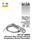
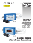
CAUTION! – This product
is not intended for medical
use or use on humans
®
User’s Guide
Shop online at
omega.com ®
e-mail: [email protected]
For latest product manuals:
omegamanual.info
OS136 SERIES
Miniature Low-Cost
Non-Contact Infrared
Temperature Sensor/Transmitter
®
OMEGAnet ® Online Service
omega.com
Internet e-mail
[email protected]
Servicing North America:
U.S.A.:
ISO 9001 Certified
Canada:
Omega Engineering, Inc., One Omega Drive, P.O. Box 4047
Stamford, CT 06907-0047 USA
Toll Free: 1-800-826-6342
TEL: (203) 359-1660
FAX: (203) 359-7700
e-mail: [email protected]
976 Bergar
Laval (Quebec), H7L 5A1 Canada
Toll-Free: 1-800-826-6342
FAX: (514) 856-6886
TEL: (514) 856-6928
e-mail: [email protected]
For immediate technical or application assistance:
U.S.A. and Canada: Sales Service: 1-800-826-6342/1-800-TC-OMEGA®
Customer Service: 1-800-622-2378/1-800-622-BEST®
Engineering Service: 1-800-872-9436/1-800-USA-WHEN®
Mexico/
Latin America:
En Español: 001 (203) 359-7803
[email protected]
FAX: 001 (203) 359-7807
e-mail: [email protected]
Servicing Europe:
Benelux:
Managed by the United Kingdom Office
Toll-Free: 0800 099 3344
TEL: +31 20 347 21 21
FAX: +31 20 643 46 43
e-mail: [email protected]
Czech Republic:
Frystatska 184
733 01 Karviná, Czech Republic
Toll-Free: 0800-1-66342
FAX: +420-59-6311114
France:
TEL: +420-59-6311899
e-mail: [email protected]
Managed by the United Kingdom Office
Toll-Free: 0800 466 342
TEL: +33 (0) 161 37 29 00
FAX: +33 (0) 130 57 54 27
e-mail: [email protected]
Germany/Austria: Daimlerstrasse 26
D-75392 Deckenpfronn, Germany
Toll-Free: 0800 6397678
FAX: +49 (0) 7056 9398-29
United Kingdom:
ISO 9001 Certified
TEL: +49 (0) 7056 9398-0
e-mail: [email protected]
OMEGA Engineering Ltd.
One Omega Drive, River Bend Technology Centre, Northbank
Irlam, Manchester M44 5BD United Kingdom
Toll-Free: 0800-488-488
TEL: +44 (0) 161 777-6611
FAX: +44 (0) 161 777-6622
e-mail: [email protected]
It is the policy of OMEGA Engineering, Inc. to comply with all worldwide safety and EMC/EMI
regulations that apply. OMEGA is constantly pursuing certification of its products to the European New
Approach Directives. OMEGA will add the CE mark to every appropriate device upon certification.
The information contained in this document is believed to be correct, but OMEGA accepts no liability for any
errors it contains, and reserves the right to alter specifications without notice.
WARNING: These products are not designed for use in, and should not be used for, human applications.
OS136 Series Miniature Low-Cost Non-Contact Infrared
Temperature Sensor/Transmitter
Table of Contents
Section
Page
Caution and Safety Information .................................................................. iii
Safety Warnings and IEC Symbols .............................................................. iii
Section 1 Introduction .................................................................................... 1
Section 2 Installation ...................................................................................... 1
2.1 Unpacking .................................................................................. 1
2.2 Electrical Connection ................................................................ 2
Section 3 Operation ......................................................................................... 3
3.1 Measuring Temperature ........................................................... 3
3.2 Ambient Temperature ............................................................... 3
3.3 Atmospheric Quality ................................................................ 4
Section 4 Laser Sight Accessory .................................................................... 6
4.1 Warnings and Caution .............................................................. 6
4.2 Operating the Laser Sight Accessory ..................................... 6
Section 5 Specifications .................................................................................. 8
5.1 General ........................................................................................ 8
5.2 Laser Sight Accessory ............................................................... 9
i
OS136 Series Miniature Low-Cost Non-Contact Infrared Temperature Sensor/Transmitter
List of Figures
ii
Figure
Description
Page
2-1
General Wiring Diagram ................................................................ 2
3-1
Optical Field of View ...................................................................... 3
3-2
Mounting Bracket, OS100-MB ....................................................... 4
3-3
Air Purge Collar, OS100-AP ........................................................... 4
3-4
Stainless Steel Housing .................................................................. 5
3-5
Water/Air Cool Jacket, OS136-WC .............................................. 5
3-6
Water/Air Cool Jacket Assembly ................................................. 5
4-1
Laser Sighting Accessory, OS100-LS ............................................. 7
4-2
Laser Warning Label........................................................................ 7
OS136 Series Miniature Low-Cost Non-Contact Infrared Temperature Sensor/Transmitter
CAUTION & SAFETY INFORMATION
If the equipment is used in a manner not specified in this manual, the protection
provided by the equipment may be impaired.
The Installation category is one (1).
There is no user replaceable fuse in this product.
The output terminals of this product are for use with equipment (Digital meters,
chart recorders, etc.) which have no accessible live parts. Such equipment should
comply with all the applicable safety requirements.
Do not operate the equipment in flammable or explosive environments.
The unit comes with a 1.82 m (6') shielded cable for power and output
connections. The cable is a multi-conductor, 24 AWG stranded wire with the
rating of 600 VDC, 205ºC, (401°F) Teflon® insulation.
Power must be disconnected before making any electrical connections.
The recommended power supply should be VDE or UL approved. Rating:12-24
VDC @ 50 mA min. power with overload protection.
The supply voltage to the transmitter should not exceed 24 VDC.
SAFETY WARNINGS AND IEC SYMBOLS
This device is marked with international safety and hazardous symbols in
accordance with IEC1010. It is important to read and follow all the precautions
and instructions in this manual before operating or commissioning this device as
it contains important information relating to safety and EMC. Failure to follow
all the safety precautions may result in injury and/or damage to your
equipment.
IEC Symbol
Description
Caution - Refer to the accompanying
document(s).
Direct Current
Laser Symbol
iii
1
Introduction
SECTION 1 - INTRODUCTION
The model OS136 series is a very low-cost, super-compact infrared transmitter. It
measures temperature via non-contact, and provides an analog output
proportional to the measured temperature. The OS136 series is offered in two
temperature ranges: -18 to 204ºC (0 to 400ºF) and 149 to 538ºC (300 to 1000ºF).
The analog output is offered as 4 to 20 mA, 0 to 5 Vdc, 0 to 10 Vdc, 10
mV/Degree C or F, or K type thermocouple.
The unit has a fixed Emissivity of 0.95 which makes it easy to measure
temperature, requiring no adjustments during installation and use.
The super-compact design, 19 mm OD x 89 mm Length (0.75" OD x 3.5" L) is
ideal to measure temperature in confined, and hard to reach places. The Stainless
Steel housing is NEMA-4 rated. The unit comes with a 1.82 m (6') shielded cable
as standard.
SECTION 2 – INSTALLATION
2.1 – Unpacking
Remove the packing list and verify that you have received all your equipment. If
you have any questions about the shipment, please call the Customer Service at:
1-800-622-2378 or 203-359-2208. We can also be reached on the internet at
omega.com
email: [email protected]
When you receive the shipment, inspect the container and the equipment for any
signs of damage. Note any evidence of rough handling in transit. Immediately
report any damage to the shipping agent.
NOTE:
The carrier will not honor any damage claims unless all the
shipping materials are saved for inspection. After
examination and removing contents, save packing material
and carton in the event reshipment is necessary.
The following items are supplied in the box:
• The infrared transmitter, OS136 with the 1.82 m (6') shielded cable.
• Two Mounting Nuts
• User’s Guide
1
Installation
2
The following describes the ordering information:
OS136 – * – ** , where
- * means:
-1 : -18 to 204ºC (0 to 400ºF) Temperature range
-2 : 149 to 538ºC (300 to 1000ºF) Temperature range
- ** means:
-MA : 4 to 20 mA current output
-V1 : 0 to 5 Vdc output
-V2 : 0 to 10 Vdc output
-K : K type thermocouple output
-MVC : 10 mV/ºC output
-MVF : 10 mV/ºF output
The following table lists the optional accessories:
Accessories
Description
Mounting Bracket
Water/Air Cooling Jacket
Air Purge Collar
Laser Sighting
Unregulated 16-24 VDC Power Supply
NIST Traceable Calibration
Model No.
OS100-MB
OS136-WC
OS100-AP
OS100-LS
PSU-93
CAL-3-IR
2.2 – Electrical Connection
The shielded cable provides the power and output connections. Fig 2-1 shows
the wiring diagram for different analog outputs.
OS136
12-24 Vdc
POWER SUPPLY
EARTH
GROUND
+
THERMOCOUPLE
METER/
–
RECORDER
+
WHITE
RED
+
–
BLACK
BLACK
–
SHIELD
SHIELD
YELLOW
RED
K TYPE
THERMOCOUPLES
-OR-
12-24 Vdc
POWER SUPPLY
EARTH
GROUND
WHITE
+
GREEN
–
DIGITAL
VOLTMETER/
AMMETER/
RECORDER
10 mV/Deg
0/5 Vdc or 4-20 mA
or 0/10 Vdc
Figure 2-1. General Wiring Diagram
2
3
Operation
SECTION 3 – OPERATION
3.1 – Measuring Temperature
Before starting to measure temperature, make sure the following check list is met:
The Power and output connections are made (Fig 2-1)
The target is larger than the optical field of view of the transmitter (Fig 3-1)
Use the Laser Sighting accessory (Optional), to align the transmitter to the
center of the target area.
The Emissivity is fixed at 0.95. No adjustment is necessary. If the target
Emissivity is less than 0.95, you can place a masking tape or paint the target
area with flat black paint to raise the surface Emissivity to 0.95.
Make sure the output load is within the product specification.
DISTANCE: SENSOR TO OBJECT (IN)
SPOT DIA.* (IN)
0"
6"
12"
24"
48"
36"
8.0"
6.0"
4.0"
2.0"
0.4"@0"
1.0"
SPOT DIA.* (CM)
D:S=6:1
1cm@0
3.3
6.6
10.0
13.0
16.0
0
20
40
60
80
100
20.0
122
DISTANCE: SENSOR TO OBJECT (CM)
* SPOT DIAMETER MEASURED AT 90% ENERGY
Figure 3-1. Optical Field of View
3.2 – Ambient Temperature
The transmitter can operate in an ambient temperature of 0 to 70°C (32 to 158°F)
without any water cool jacket. It can operate from 0 to 200°C (32 to 392°F) with
the water cool jacket accessory, OS136-WC (Fig 3-5 & 3-6). It can operate up to
110°C (230°F) with air cooling.
There is a warm up period of 1 to 2 minutes after power up. After the warm up
period, temperature measurement can be made.
When the ambient temperature around the transmitter changes abruptly, the sensor
head goes through a thermal shock. It takes a certain amount of time for the sensor
head to get stabilized to the new ambient temperature. For example, it takes about
30 minutes for the transmitter to stabilize from 25°C to 50°C ambient temperature.
3
Operation
3
3.3 - Atmospheric Quality
Environments with smoke , dust, and fume dirty up the optical lens, and cause
erroneous temperature readings. To keep the surface of the optical lens clean, the
air purge collar accessory is recommended, OS136-AP (Fig 3-3).
The following figures show the Mounting Bracket (OS136-MB), Air Purge Collar
(OS136-AP), Stainless Steel Housing, Water/Air Cool Jacket (OS136-WC), and
the Water/Air Cool Jacket Assembly.
12.7
(0.5)
3.2
(1/8)
12.7
(0.5)
50.0
(1.97)
90°
Ø 19
(0.755)
3.2
(1/8)
Ø4
(0.156)
23.3
(0.919)
31.8
(1.25)
42.9
(1.69)
25.4
(1)
Dimensions mm (in.)
Figure 3-2. Mounting Bracket, OS100-MB
17.5
(0.69)
28.6
(1.125)
Dimensions mm (in.)
3/4-16 UNF 2B
THRU.
1/16 NPT
COMPRESSION
FITTING
Figure 3-3. Air Purge Collar, OS100-AP
4
Operation
3/4-16 UNF
LIGHT HEX KNURL
4.76 (3/16) WIDE
19.05
(0.75)
33.27
(1.31)
88.9
(3.5)
1.83m
(6ft)
DIMENSIONS mm (in)
Figure 3-4. Stainless Steel Housing
1/8 NPT COMPRESSION
FITTING, 2 PLCS.
7.62
(0.30)
34.80
(1.37)
3
INLET
OUTLET
85.09
(3.35)
3/4-16 UNF-2B
3/4-16 UNF
Dimensions mm (in.)
Figure 3-5. Water/Air Cool Jacket, OS136-WC
MOUNTING
BRACKET
MOUNTING
NUT
OS137
INTLET
OUTLET
UP TO 200°C (392°F) AMBIENT TEMPERATURE WITH WATER COOLING
Dimensions mm (in.)
Figure 3-6. Water/Air Cool Jacket Assembly
5
Laser Sight Accessory
4
SECTION 4 - LASER SIGHT ACCESSORY
4.1 – Warning and Caution
CAUTION:
You may receive harmful laser radiation exposure if you do
not adhere to the warnings listed below:
• USE OF CONTROLS OR ADJUSTMENTS OR PERFORMANCE OF
PROCEDURES OTHER THAN THOSE SPECIFIED HERE MAY RESULT IN
HAZARDOUS RADIATION EXPOSURE.
• DO NOT LOOK AT THE LASER BEAM COMING OUT OF THE LENS OR
VIEW DIRECTLY WITH OPTICAL INSTRUMENTS – EYE DAMAGE CAN
RESULT.
• USE EXTREME CAUTION WHEN OPERATING THE LASER SIGHT
ACCESSORY
• NEVER POINT THE LASER ACCESSORY AT A PERSON
• KEEP OUT OF REACH OF ALL CHILDREN
WARNING:
Do not attempt to open the laser sight accessory. There are no
user serviceable parts inside.
4.2 – Operating the Laser Sight Accessory
The Laser sight accessory screws onto the front of the transmitter sensor head.
This accessory is only used for alignment of the transmitter head to the target
area. After the alignment process, the accessory has to be removed from the front
of the transmitter head before temperature measurement is made.
The laser sight accessory is powered from a small, compact battery pack
(included with the accessory). Connect the battery pack to the accessory using
the cable provided. Aim at the target, and turn on the battery power using the
slide switch on the battery pack. Adjust the sensor head position such that the
laser beam points to the center of the target area. Turn off the battery pack, and
remove the laser sighting accessory from the sensor head (Fig 4-1).
6
4
Laser Sight Accessory
LASER WARNING LABEL
38.1
(1.5)
DC POWER JACK
OS136
19
(0.75)
ON/OFF
SWITCH
LED LASER
POWER
LASER
INDICATOR BEAM
50.8
(2.0)
POWER
CABLE
BATTERY PACK
POWER SUPPLY
Dimensions mm (in.)
Figure 4-1. Laser Sighting Accessory, OS100-LS
®
LASER RADIATION DO NOT STARE
INTO BEAM OR VIEW DIRECTLY WITH
OPTICAL INSTRUMENTS. CLASS 2
LASER PRODUCT.
LASER RADIATION - DO NOT STARE INTO
CAUTION
AVOID EXPOSURE. LASER
IS EMITTED
BEAM RADIATION
FROM THIS APERTURE.
OUTPUT <1 mW, WAVELENGTH 630-670 nm, CLASS II (2) LASER
PRODUCT. COMPLIES WITH FDA 21CFR 1040.10 & EN60825-1/11.2001
Figure 4-2. Laser Warning Label
7
Specifications
5
SECTION 5 – SPECIFICATIONS
5.1 - General
Temperature Range:
OS136-1
OS136-2
Accuracy: @22ºC (72ºF) ambient
OS136-1
OS136-2
-18 to 204ºC (0 to 400ºF)
149 to 538ºC (300 to 1000ºF)
3% of Rdg or 4.4ºC (8ºF) whichever is greater
3% of Rdg or 5.5ºC (10ºF) whichever is greater
From 185 to 510ºC (365 to 950ºF)
Repeatability:
1% of Rdg.
Optical Field of View:
6 to 1 (Distance to Spot Size)
Spectral Response:
5 to 14 microns
Response Time:
150 msec, 0 to 63% of final value
Emissivity:
Fixed at 0.95
Analog output:
MA
V1
V2
K
MVC
MVF
4 to 20 mA
0 to 5 Vdc
0 to 10 Vdc
K type Thermocouple, compensated
10 mV/ºC
10 mV/ºF
Output Load Requirements:
Min. Load (0 to 5 Vdc)
Min. Load (0 to 10 Vdc)
Max. Load (4 to 20 mA)
Min. Load (10 mV/Deg)
Min. Load (K T/C)
1 K-Ohms
2 K-Ohms
(Power Supply – 4) / 20 mA
10 K-Ohms
100 K-Ohms
Operating Ambient Temperature:
No Water Cooling
0 to 70ºC (32 to 158ºF)
With Water Cooling (OS136-WC) 0 to 200ºC (32 to 392ºF)
With Air Cooling (OS136-WC) 0 to 110°C (32 to 230°F)
Operating Relative Humidity:
Less than 95% RH, non-condensing
Water Flow Rate for OS136-WC:
0.25 GPM, room temperature, minimum
Air Flow Rate for OS136-WC
5 CFM (2.4 liters/sec)
Warm up Period:
1 to 2 minutes
Thermal Shock:
About 30 minutes for 25ºC abrupt
ambient temperature change
Air Flow Rate for Air Purge Collar 1 CFM (0.5 liters/sec.)
Transmitter Housing:
Stainless Steel 316, NEMA-4 & IP65 rated
Power:
12 to 24 VDC @ 50 mA
Dimensions:
19 OD x 89 L mm (0.75" OD x 3.5" L)
Weight:
0.40 lb (181 g)
8
5
Specifications
5.2 - Laser Sight Accessory
9
Laser Wavelength (Color):
630 - 670 nm (Red)
Operating Distance:
Up to 9.1 m (30 ft.)
Max. Laser Power Output:
Less than 1 mW @ 22ºC ambient
European Classification:
Class 2, EN60825-1/11.2001
FDA Classification:
Class II Laser Product. Complies with
21 CFR 1040.10
Laser Beam Diameter:
Less than 5 mm
Beam Divergence:
Less than 2 mrad
Operating Temperature:
0 to 50°C (32 to 122°F)
Operating Relative Humidity:
Less than 95% RH, non-condensing
Power Switch:
ON/OFF, Slide switch on the Battery Pack
Power Indicator:
Red LED
Power:
Battery Pack, 3 VDC
Caution & Certification Label:
Located on the head sight circumference
Identification Label:
Located on the head sight circumference
Aperture Label:
Located on the head sight circumference
Dimensions:
38 OD x 50.8 L mm (1.5" OD x 2" L)
WARRANTY/DISCLAIMER
OMEGA ENGINEERING, INC. warrants this unit to be free of defects in materials and workmanship for a
period of 13 months from date of purchase. OMEGA’s WARRANTY adds an additional one (1) month
grace period to the normal one (1) year product warranty to cover handling and shipping time. This
ensures that OMEGA’s customers receive maximum coverage on each product.
If the unit malfunctions, it must be returned to the factory for evaluation. OMEGA’s Customer Service
Department will issue an Authorized Return (AR) number immediately upon phone or written request.
Upon examination by OMEGA, if the unit is found to be defective, it will be repaired or replaced at no
charge. OMEGA’s WARRANTY does not apply to defects resulting from any action of the purchaser,
including but not limited to mishandling, improper interfacing, operation outside of design limits,
improper repair, or unauthorized modification. This WARRANTY is VOID if the unit shows evidence of
having been tampered with or shows evidence of having been damaged as a result of excessive corrosion;
or current, heat, moisture or vibration; improper specification; misapplication; misuse or other operating
conditions outside of OMEGA’s control. Components in which wear is not warranted, include but are not
limited to contact points, fuses, and triacs.
OMEGA is pleased to offer suggestions on the use of its various products. However,
OMEGA neither assumes responsibility for any omissions or errors nor assumes liability for any
damages that result from the use of its products in accordance with information provided by
OMEGA, either verbal or written. OMEGA warrants only that the parts manufactured by the
company will be as specified and free of defects. OMEGA MAKES NO OTHER WARRANTIES OR
REPRESENTATIONS OF ANY KIND WHATSOEVER, EXPRESSED OR IMPLIED, EXCEPT THAT OF
TITLE, AND ALL IMPLIED WARRANTIES INCLUDING ANY WARRANTY OF MERCHANTABILITY
AND FITNESS FOR A PARTICULAR PURPOSE ARE HEREBY DISCLAIMED. LIMITATION OF
LIABILITY: The remedies of purchaser set forth herein are exclusive, and the total liability of
OMEGA with respect to this order, whether based on contract, warranty, negligence,
indemnification, strict liability or otherwise, shall not exceed the purchase price of the
component upon which liability is based. In no event shall OMEGA be liable for
consequential, incidental or special damages.
CONDITIONS: Equipment sold by OMEGA is not intended to be used, nor shall it be used: (1) as a “Basic
Component” under 10 CFR 21 (NRC), used in or with any nuclear installation or activity; or (2) in medical
applications or used on humans. Should any Product(s) be used in or with any nuclear installation or
activity, medical application, used on humans, or misused in any way, OMEGA assumes no responsibility
as set forth in our basic WARRANTY/DISCLAIMER language, and, additionally, purchaser will indemnify
OMEGA and hold OMEGA harmless from any liability or damage whatsoever arising out of the use of the
Product(s) in such a manner.
RETURN REQUESTS/INQUIRIES
Direct all warranty and repair requests/inquiries to the OMEGA Customer Service Department. BEFORE
RETURNING ANY PRODUCT(S) TO OMEGA, PURCHASER MUST OBTAIN AN AUTHORIZED RETURN
(AR) NUMBER FROM OMEGA’S CUSTOMER SERVICE DEPARTMENT (IN ORDER TO AVOID
PROCESSING DELAYS). The assigned AR number should then be marked on the outside of the return
package and on any correspondence.
The purchaser is responsible for shipping charges, freight, insurance and proper packaging to prevent
breakage in transit.
FOR WARRANTY RETURNS, please have the
following information available BEFORE
contacting OMEGA:
1. Purchase Order number under which the product
was PURCHASED,
2. Model and serial number of the product under
warranty, and
3. Repair instructions and/or specific problems
relative to the product.
FOR NON-WARRANTY REPAIRS, consult OMEGA
for current repair charges. Have the following
information available BEFORE contacting OMEGA:
1. Purchase Order number to cover the COST
of the repair,
2. Model and serial number of the product, and
3. Repair instructions and/or specific problems
relative to the product.
OMEGA’s policy is to make running changes, not model changes, whenever an improvement is possible. This affords
our customers the latest in technology and engineering.
OMEGA is a registered trademark of OMEGA ENGINEERING, INC.
© Copyright 2011 OMEGA ENGINEERING, INC. All rights reserved. This document may not be copied, photocopied,
reproduced, translated, or reduced to any electronic medium or machine-readable form, in whole or in part, without the
prior written consent of OMEGA ENGINEERING, INC.
Where Do I Find Everything I Need for
Process Measurement and Control?
OMEGA…Of Course!
Shop online at omega.com SM
TEMPERATURE
Thermocouple, RTD & Thermistor Probes, Connectors, Panels & Assemblies
Wire: Thermocouple, RTD & Thermistor
Calibrators & Ice Point References
Recorders, Controllers & Process Monitors
Infrared Pyrometers
PRESSURE, STRAIN AND FORCE
Transducers & Strain Gages
Load Cells & Pressure Gages
Displacement Transducers
Instrumentation & Accessories
FLOW/LEVEL
Rotameters, Gas Mass Flowmeters & Flow Computers
Air Velocity Indicators
Turbine/Paddlewheel Systems
Totalizers & Batch Controllers
pH/CONDUCTIVITY
pH Electrodes, Testers & Accessories
Benchtop/Laboratory Meters
Controllers, Calibrators, Simulators & Pumps
Industrial pH & Conductivity Equipment
DATA ACQUISITION
Data Acquisition & Engineering Software
Communications-Based Acquisition Systems
Plug-in Cards for Apple, IBM & Compatibles
Data Logging Systems
Recorders, Printers & Plotters
HEATERS
Heating Cable
Cartridge & Strip Heaters
Immersion & Band Heaters
Flexible Heaters
Laboratory Heaters
ENVIRONMENTAL
MONITORING AND CONTROL
Metering & Control Instrumentation
Refractometers
Pumps & Tubing
Air, Soil & Water Monitors
Industrial Water & Wastewater Treatment
pH, Conductivity & Dissolved Oxygen Instruments
M3946/1211