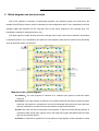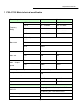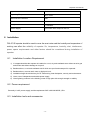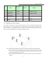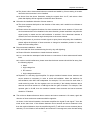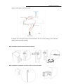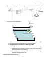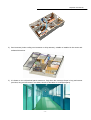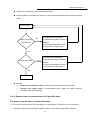
1
Industrial Repeater
F20~27-5S
Repeater User Manual
1
Safety Warnings _____________________________________________________________________ 3
2
Why repeater ________________________________________________________________________ 4
2.1
Reason__________________________________________________________________ 4
3
Introduction_________________________________________________________________________ 5
4
System Characteristics ______________________________________________________________ 6
4.1
Features _________________________________________________________________ 6
4.2
Appearance of F20~27-5S repeaters ___________________________________________ 6
5
Block diagram and work principle ____________________________________________________ 7
6
The repeater system _________________________________________________________________ 8
7
F20~27-5S Main technical specification _______________________________________________ 9
8
Installation _________________________________________________________________________ 10
8.1
Installation Location Requirement ____________________________________________ 10
8.2
Power requirement ________________________________________________________ 10
8.3
Installation tools and accessories_____________________________________________ 10
8.4
Installation of donor antenna ________________________________________________ 11
8.5
Indoor antenna installation __________________________________________________ 15
8.6
Repeater Installation ______________________________________________________ 17
8.6.1
Installation Steps______________________________________________________________________ 17
8.6.2
Repeater’s ports description _____________________________________________________________ 17
8.6.3
Accessories selection __________________________________________________________________ 18
8.7
Repeater Settings ________________________________________________________ 18
8.7.1
Switch on power ______________________________________________________________________ 18
8.7.2
Parameters setting ____________________________________________________________________ 19
8.7.3
Repeater Commissioning _______________________________________________________________ 19
8.8
System Test _____________________________________________________________ 21
8.8.1
Check whether the coverage is good ______________________________________________________ 21
8.8.2
Repeater can not communicate in Power-ON status __________________________________________ 22
-2-
Repeater User Manual
Preface
This user’s manual describes the installation, commissioning and maintenance of
industrial F20~27-5S repeaters. Please do read the user manual carefully before
installing and maintaining F20~27-5S repeaters. The information in this manual is
subject to change without prior notice. Opinions are welcomed about the manual
improvement.
1 Safety Warnings
Users must follow the below principles:
l
Repeater should follow system requirement of communication equipment, assure good
groundings and lightning protection.
l
The power supply voltage of repeater should meet the standards of security
requirement; any operation shall be carried out only after cutting off power in advance.
Only the professional is authorized for the operation.
l
Do not dismantle machine, maintain or displace accessories by yourself, because in
this way, the equipment may be damaged or even get an electric shock.
l
Do not open the repeater; touch the module of repeater, or to open the cover of module
to touch the electronic component, the components will be damaged due to electrostatic.
l
Please keep away from heating-equipment, because the repeater will dissipate heat
during operation. And do not cover repeater with anything that influences
heat-dissipation.
-3-
Repeater User Manual
2 Why repeater
2.1 Reason
1) Blind or weak signal areas are formed if the buildings are too far away from BTS, or the buildings
themselves shield or absorb the signals.
2) There are too many complicated signals in the higher part of the buildings, therefore ping-pong
switching effect has been formed and the signals fluctuate a lot, there are annoying noises during
phone calls and there are dropped phone calls accordingly.
3) Elevators and basements are well-known blind areas.
4) Downtown areas of the cities, congested with many high-rise buildings are usually the weak or blind
areas.
Question: Will repeater increase the RF radiation?
A: No, it will decrease instead.
As it can be searched easily through internet, the tower would “order” the mobile phone to increase its
output power, in order to ensure successful connection when the mobile signal bar is few, there will be
stronger mobile output power level when the mobile signal bar is less and the strongest one can reach 2W
(GSM); moreover, the mobile phone is usually as near as less than 5cm to human body when people are
in phone calls. Not only it influences badly the human bodies, but also run out of the battery power much
more quickly; usually the mobile phone gets hot in such status.
The maximum power levels of F20-27-5S repeaters are 0.1w to 0.5w, and it decreases to be maximum
0.05W when reaching server antenna. And since the server antenna is installed over the ceiling or onto
the wall, there is usually more than 3 meter away from the human body, 3meter away means at least 40dB
propagation loss, or 10000 times less, 0.000005W, and therefore it is too weak to influence human bodies
although it is still a very good signal for mobile phones.
And when a repeater is installed, it improves the mobile signals in the coverage, and the successful phone
call can be connected easily with a much less power level of the mobile phone, thus it will reduce
tremendously the RF radiation.
-4-
Repeater User Manual
3 Introduction
F20~27-5S full duplex mobile communication repeaters from Huaptec are the perfect solution for providing
a wireless improvement in the cellular reception of a high-rise building, basement, hotel, shopping mall,
tunnel and etc., in the quickest time possible. One repeater’s indoor coverage can reach 5000 to 60000
square feet.
They are designed to improve the call quality of an area by receiving, amplifying and re-transmitting signals
of the base station into a specified area via the server antenna of the repeater.
This repeater has Manual Gain Control (MGC) feature that enables engineers to reduce the gain of the
repeater manually if oscillation is detected or too strong input power level during installation, this will help to
get the best coverage effect without any interference back to mobile network.
To maintain safe and specific output signal levels during the repeater’s operation, this repeater has a built-in
signal oscillation detection circuit to adjust the gain automatically so as to avoid interference to the cellular
network, also it gets color changing LED’s indicate its environmental status: the Alarm LED’s located on the
front of the unit (Alarm Low & Alarm High) will change color from green to orange or red, (depending on the
input power level) if the system detects signal oscillation in either band or, if the input signal is beyond a safe
limit.
Below diagram shows how simple and fast F20~27-5S repeater system is installed and works effectively.
One donor antenna, has been installed at the top of the roof to pick up good mobile signals from outside,
and send through coaxial cable to a F20~27-5S repeater to be amplified significantly, then the output
signals are divided into two signals or more by splitters and couplers, adopt a few omni-directional and
panel antennas to retransmit signal to the coverage. Very clear phone call or high speed mobile data
services are immediately available within the area.
-5-
Repeater User Manual
4 System Characteristics
4.1 Features
l
Streamline shape
l
Excellent out of band rejection
l
Wide power supply range and low power consumption
l
High-integration (One board to contain low-noise amplifier, frequency selection module, power
amplifier module, both uplink and downlink one for all)
l
Manual gain control provides a variety of applications
l MTBF>50000h, low failure rate
4.2 Appearance of F20~27-5S repeaters
Figure 1 the front view (colors may differ from real products).
-6-
Repeater User Manual
5 Block diagram and work principle
F20~27-5S repeater is basically a bi-directional amplifier, the downlink signals are received by the
repeater from BTS by the donor antenna, filtered by its internal duplexers and FC unit, amplified by low noise
amplifier (LNA) and downlink PA unit, and then sent via the server antenna to the coverage area. The
bandwidth is operators’ working frequency only.
The uplink signal of mobile terminal from the coverage area is input via the server antenna, then filtered
by duplexers and FC unit, amplified by the uplink low noise amplifier (LNA) and the uplink PA unit and finally
sent via the donor antenna to the BTS.
Modules in the system diagram:
l Combiner:The main purpose of combiner is to combine quint system to share the same
antennas.
l Duplexer: The main purpose of duplexer is to combine downlink and uplink to share the same
antennas, the duplexer is composed of one pair of band pass filter that can not only reject the
spurious interference, but also increase the isolation of Uplink and Downlink.
l LNA: LNA is the first active sub system of the repeater, of which low noise and high linearity is
requested under strong input signals. LNA is the major sub system that determines the noise
figure of the repeater system.
l IF Filter: IF SAW filer is adopted in FC sub system to reject signals of other operators to make
-7-
Repeater User Manual
sure the signals clean and increase the UL and DL isolation.
l PA: The power amplifier sub system helps the repeater to reach its targeted output power,
linearity of which decides the linearity of the repeater.
l Power supply is to supply power electricity to all repeaters’ modules.
6 The repeater system
l Donor Antenna:
Ø 5~7dbi outdoor panel or 7~9dBi wide band Yagi are recommended as donor antenna.
Ø Function: Pick up donor signals from the BTS and send to the repeater by cable; the
received signals’ power level and quality influence a lot on the coverage effect. Donor
antenna also transmits the uplink signals from the repeater to BTS.
l Server Antenna:
Ø 2~3dBi indoor omni ceiling or 5~7dBi indoor panel are recommended.
Ø Omni antenna (Indoor ceiling omni antenna or whip antenna), suitable to installed in the
center and radiate all direction; It is better to use a directional panel antenna or Yagi when
the coverage shape is long and narrow (corridors, long row of houses in two sides, tunnels
or elevators or rural open space).
l Cables: LMR 300 or 400, 5D or 8D –FB coax cables are recommended.
l Splitters or couplers: when the building structure is too complicated or there is big loss due to
thick walls, etc., splitters or couplers shall be used so that more antennas can be installed in
more areas to distribute the signals to each corner of the coverage area.
l Power Box including electricity meter, air switch and groundings, some sites might need surge
arrestors.
-8-
Repeater User Manual
7 F20~27-5S Main technical specification
Electrical specification
Frequency
Range
Band width
Max. Gain
Max.
Output
power
Uplink
Downlink
LTE(A+B)
704 ~ 716 MHz
734 ~ 746 MHz
LTE C
776 ~ 787MHz
746 ~ 757 MHz
CDMA
824 ~ 849MHz
869 ~ 894MHz
PCS
1850 ~ 1910MHz
1930 ~ 1990MHz
AWS
1710 ~ 1755MHz
2110 ~ 2155MHz
LTE(A+B)
12MHz
LTE C
11MHz
CDMA
25MHz
PCS
60MHz
AWS
45MHz
F20
65dB
70dB
F23
70dB
70dB
F27
75dB
75dB
F20
20dBm
20dBm
F23
20dBm
23dBm
F27
20dBm
27dBm
MGC (Step Attenuation)
≧31dB / 1dB step
Intelligent AGC
51dB
Automatic Level Control
≥ 15dB, auto shut off after 15dB
Inter-modulation
≦-19dBm
≦-19dBm
Spurious
≦-19dBm
≦-19dBm
Power LED
Power Indicator
Orange @ ALC 1~5dB, Red @ ALC 15dB
ALC LED
LED Blinking after 5 seconds red color
Mechanical Specifications
Standard
I/O Port
N-Female
-9-
Repeater User Manual
Impedance
50 ohm
Operating Temperature
10ºC~+55ºC
Environment Conditions
IP40
Dimensions
4.7*7.8 *1.6inch/120*198*40mm
Weight
≤11lbs/5KG
Power Supply
Input AC90~264V,output DC12V/7A
8 Installation
F20~27-5S repeater should be used to cover the area indoor and the humidity and temperature of
working can affect the reliability of repeater. So, temperature, humidity, dust, interference,
power, space requirements and other factors should be considered during installation of
repeater.
8.1
Installation Location Requirement
1) It is appreciated that the repeater is installed in a cool, dry and ventilated room without erosive gas
and smoke and without leakage on its proof.
2) Besides above, a cool and ventilated wall of which sun-proof and waterproof is expected.
3) Besides above, common wall, tower or high pole is ok.
4) Installation height should be easy for RF cable wiring, heat dissipation, security and maintenance.
5) Have a set of independent and stable power supply.
6) Have lightning conducer in the building, tower or high pole with enough strength or stability.
8.2 Power requirement
Generally it is AC power supply, and the requirement of AC is 90~264VAC/50±5Hz.
8.3 Installation tools and accessories
- 10 -
Repeater User Manual
N
Specificati
o
Name
Quantity
Remark
on
.
1
Plastic
Expansion Bolt
M5*24
6
Standard accessories
2
Tapping screw
M3*30
4
Standard accessories
3
Hanging folder
1
Standard accessories
4
reciprocating drill
1
Engineering-owned, punch
the wall
5
Shot bit
1
Engineering-owned, punch
the wall
M3
8.4 Installation of donor antenna
The repeater’s main function is to improve weak RF signals to an area. A simple formula: Input power+
Gain= Output power. The signal strength from the outdoor antenna directly affects the efficiency of the
indoor coverage. It is very important to choose the location of the outdoor antenna carefully. With this in
mind, it is not recommended the donor antenna to be installed in an attic.
n
Testing the signal strength received from donor antenna mounted in site by mobile phone:
l Please select the top of the building to install the donor antenna if the total floors are less
than 7, and must select a place like balcony or platform lower than 7th floor for the donor
antenna if the buildings are over 7 floors.
l The mobile phone shall display full bar signals in location where the donor antenna is
installed
- 11 -
Repeater User Manual
l The phone calls or data transmission are smooth and stable by 3 times testing in location
where the donor antenna is to be installed.
l As shown from the above illustration, testing the signals from A to E, and select a best
place that displays full bar signals to install the donor antenna.
n
Selection the installation direction of donor antenna.
l The donor antenna shall point to the direction of the tower, and it would be much better to
keep line of sight.
l Please select the opposite directions for donor antenna and server antenna. If donor and
server antennas have to be installed in the same direction, please install them only after the
signal quality is tested and the self-oscillation is avoided. If the directional antenna is
selected, the main directional angle should point to the tower antenna.
l If the performance is poor due to weak signals or poor phone call quality after installation,
please adjust the direction of donor antenna or change its installation position in order to
obtain the best calling effect.
n
Donor antenna installation ---Notes:
l Do not install the donor antenna during the rainy day with lightning.
l Please follow the instructions to install the donor antenna.
l It is a must that the waterproof shall be done to connectors of donor antenna and feeder
lines.
l In order to avoid interference, please note that the donor antenna should be far away from
the following objects.
² Metal
² High-voltage line
² RF antenna
² High-voltage transformer
l Repeater is a two-way signal amplifier. So proper isolation between donor antenna and
server antenna is necessary in order to avoid self-oscillation. About the definition for
self-oscillation, take MIC and loudspeaker for example; if it is too close for each other, it
could make big noise. So the repeater can run smoothly if the isolation between donor
antenna and server antenna is 15 dB higher than the gain of booster. For example, if the
repeater gain is 60 dB, then the isolation between donor antenna and server antenna
should be 75 decibel.
n
The minimum distance between donor antenna and server antenna is 10 meters; again the
direction of donor and server antennas shall be opposite.
As shown in the below illustration, the booster amplifies the signal R and signal T from the
tower at the same time. If the distance between donor antenna and server antenna is less
than the required distance, then the amplified signal R (T) will back to server antenna (donor
antenna). So it will lead to self-oscillation and reduce the coverage area, also the bad calling
- 12 -
Repeater User Manual
quality could happen at the same time.
If isolation can’t be achieved by the limited distance, the roof of the building or other barriers
can be used to increase isolation.
n
Installation of panel antenna as donor antenna
n
Installation of logarithmic periodic antenna as donor antenna
- 13 -
Repeater User Manual
n
Installation of YAGI antenna as donor antenna
n
Test the call quality of donor antenna
Lightening
Test Engineer Phone
Fix the donor antenna after selecting the best position, and adjust slightly its height or angles
in order to get the signals with suitable input power level and calling Quality.
l System Requirement of LTE(A+B), LTE C, CDMA, PCS, and AWS
1)
The total input power level shall be around -50dBm, lowest shall be more than
–80dBm
2)
Test by mobile phone or data card by 3~5 times to make sure the calling quality is
good in 95% of the time, and no handovers.
3)
It is requested that the leading signal shall be 6dBi higher than the second (for
professional engineering reference only).
Cable layout and connector assembly:
- 14 -
Repeater User Manual
1) Keep the type, specifications, routing direction, location, and curvature radius of cables in compliance
with the design requirement. Place cables in good order, bend them smoothly, and protect the outer
skin against any damage.
2) Bind cables in good order when laying them on cable racks. Keep cables within cable troughs, without
any cross, when you do not bind them. When leading cables in or out of troughs, use a hole-opener to
open cable troughs and then install PVC lock-nuts to protect them.
3) Keep horizontal cables straight and fasten them stably with a fixing clip every 1 to 1.5 meters, with a
proper stress.
4) Bind and fasten vertical cables every two to three meters to avoid damaging cables or connectors
owing to their own heavy weight. Take back the cables and re-lay them when you have difficulty in
pulling them, and avoid using a strong force to pull them.
5) Separate RF cables from power cables. Take proper isolation measures if they have to be placed on
the same cable racks owing to the site condition restriction.
6) Correctly fasten all connection parts of the whole system, from the antenna to active interfaces to
passive interfaces, and keep electrical interfaces well contacted. Give waterproof treatment to outdoor
connection parts.
7) Take lightning protection measures for the antenna and feeder system in accordance with the design
requirement. Avoid deforming the antenna feeder where grounding clips are placed, and give
waterproof treatment to the feeder.
8) Keep exposed indoor cables in good order. Install PVC troughs or tubes if the exposed cables are
more than 1 meter long. Place small passive RF parts such as power splitter in cable troughs.
9) Process both ends of RF coaxial cables as follows:
Keep the same redundant cable length and keep the length of stripped cables to agree with the
corresponding connectors.
Use a proper force to cut the jacket layer or insulation layer and avoid damaging the braid shielded net
and cores.
Weld cores firmly and smoothly with a proper amount of solder, without solder projections or nodules.
Assemble coaxial cables strictly in accordance with the installation specifications.
Keep a moderate length of heat-shrinkable tubes and heat-shrink the tubes evenly when adding
heat-shrinkable tubes to the end of cables.
Protect the ends of cables against water and dampness. Use waterproof tape to give waterproof
treatment to exposed cable ends. Cut off the end if it is dampened or water-soaked.
8.5
Indoor antenna installation
Proper antennas shall be selected according to the site conditions and the requirement.
1) Indoor panel antenna, suitable to be installed in the corner and radiate to other side.
- 15 -
Repeater User Manual
2) Omni antenna (Indoor ceiling omni antenna or whip antenna), suitable to installed in the center and
radiate all directions.
3) It is better to use a directional panel antenna or Yagi when the coverage shape is long and narrow
(corridors, long row of houses in two sides, tunnels or elevators or rural open space).
- 16 -
Repeater User Manual
8.6 Repeater Installation
8.6.1 Installation Steps
1)
Drill holes on the selected place and install expansion bolts.
2)
Align the holes on the installing support with the expansion bolts, keep the installing support
vertical, place flat washers, spring washers, and nuts in turn, and tighten the nuts to fasten the
installing support.
3)
Place the repeater on the support and fasten it.
4)
Connect cables and power cables to the repeater respectively.
5)
After installing the repeater as described as above, power on the repeater to check the operation
status.
8.6.2 Repeater’s ports description
1)
Outdoor port: connected with the donor antenna by cable.
2)
Indoor port: connected with server antenna directly or by cable.
3)
AC IN: connected with power supply.
- 17 -
Repeater User Manual
AC IN port
Indoor port
Outdoor port
8.6.3 Accessories selection
Please pay attention to the two points of “frequency” and “impedance” during the selection of the
accessories. All accessories shall support the repeater’s frequencies from feeder line, antenna and splitter
to combiners etc. For example, the repeater’s frequency is GSM900, so all the accessories must support
the GSM900 frequency. And the repeater’s impedance is 50ohm, so the accessories shall all be 50ohm. To
use any other impedance of coax will put an extra load on your repeater, shorten its life span and decrease
the system performance.
8.7
Repeater Settings
Please check very carefully all cable connections are correct and firm before running operation test and
then carry out following tests
8.7.1 Switch on power
After power is on, check firstly the alarm and power LED.
l
l
Status and definition of POWER indicators:
Status
Definition
Green
Normal
Off
DC power problem
Status and Definition of ALARM indicators,
Status
Green
ALARM
It is working in linearity
- 18 -
Repeater User Manual
Warning: Input signals may be not enough, so please check on coverage
effect, do not do anything if it is good; otherwise please check the donor
antenna position.
There are strong input signals or severe self oscillation. The status can
Red
only maintain 5 seconds with auto shut off function. Please check the
troubleshooting or FAQ to get solutions.
A little bit stronger input signals or slight self oscillation have occurred.
Orange
Solution: Please adjust antennas or slowly add the loss by MGC till the
indicator turning to green. Stop immediately when the color changes
which can provide the best coverage.
Booster breaks down, or severe self oscillation leads to auto mute. Please
Off
re-plug in and check if alarm LED turns red, if it is, please take same
measures like above; if it maintains off which means the power breaks
down.
8.7.2 Parameters setting
8.7.3 Repeater Commissioning
l The curve about device working status
- 19 -
Repeater User Manual
POutput Power
Critical stable
Pmax
point
(Pinput
Green LED
linear
LED
Orange LED Red
Equipment
Stable work
Output power, input signal and their
POutput Power: Output Power
Pinput Power: Input Power
VATT: Attenuation value of attenuator
Pinput Power -VATT: Input Power-Attenuation value of attenuator
Pmax: Rate output power
l Downlink gain setting
First the alarm LED only indicates the downlink input power level, here we use color of Alarm
LED to adjust the gain of the repeater. As for the downlink working performance, Alarm LED of
“Green” color and with the intention of turning orange is a good working point; here we refer as “edge
point”. At this time, downlink output power and coverage effect are stable.
And the equipment must be as far as possible away from overloading status of “red” (the equipment
would hold higher interference and depression ability at this stage). So we try our best to set the
equipment near “edge point” of green and intention of turning orange during engineering.
l Setting of “edge point”:
Switch on the power supply after connection with donor antenna and server antenna, and
observe ALARM LED.
n If it shines “orange”, use 1dB as step to reduce the gain until “green” turns on, then increase the
gain 1~3dB attenuation value until “orange” starts to turn on, then brings back 1~2dB till “green” is
on, then fix the gain and the repeater’s downlink output power reaches the perfect status.
n If it shines “green”, then:
u To check whether the attenuation value has been set, if it is, use 1dB as step to increase gain
- 20 -
Repeater User Manual
until the “orange” turns on, then brings back 1~2dB till “green” is on again , then the repeater’s
downlink output power reaches the perfect status.
u But if attenuation is not set, it indicates that the input power is not enough.
²
Then please check coverage effect first, if the coverage effect is good, the engineering has
reached expecting target.
²
But if the coverage effect is not good, the donor antenna should be adjusted to get a
stronger signal until “orange” intends to turn on or the effect reaches the target. At this
stage, please make sure “Orange” color is not generated by self oscillation. Please take off
the server antenna to test if it is self oscillation or not: if the Orange turns to be Orange, it
is self oscillation; if it stays as Orange, it is not self oscillation.
l Uplink gain setting
Standard: uplink attenuation values =downlink attenuation values
Remark: Keep in mind that you do not want to have more than a 5dB difference between the uplink
and downlink values for optimum system performance, and it is better to keep the same attenuation
value of Uplink with that of Downlink.
8.8 System Test
8.8.1 Check whether the coverage is good
1) Have a test with mobile phone or data card (engineering mobile phone is preferred). If the signals in
most areas have not been improved, please check below again:
u The weak input signal leads to the low output power. Change the direction of donor antenna or
its installation position or replace donor antenna with higher gain to increase input signal
power level.
u Check whether it is necessary to add more server antennas due to barriers, whether the
repeater’s
u Power is enough; please install more server antennas or change with a repeater with higher
power level.
2) If the signals in small part of the areas have not been improved, please check below:
u Check whether the service antenna is installed correctly or not, you may try to move the
antenna location to improve coverage.
- 21 -
Repeater User Manual
u Check if it is necessary to use a directional antenna.
u Check whether it is necessary to add one or more antenna to enhance the coverage of special
areas.
Test coverage
Check the signal
strength is fit
No
1) Mobility Service antenna
2) increase the number of service
antenna
3) reduce the attenuation values
4) increase the output power
Yes
Check call quality
No
1) Mobility Service antenna
2) increase the number of service
antenna
3) reduce the attenuation values
4) increase the output power
Yes
Completion
u Remark:
²
Reduce the attenuation values---at the same time must ensure the isolation.
²
Increase the output power ---recommended ways: adjust the donor antenna;
increased input signal strength.
8.8.2 Repeater can not communicate in Power-ON status
The power is on but there is signal fluctuation
1) The power is on but it has a signal fluctuation or a flash signal. The phone call can not achieve.
It shall be caused by the insufficient isolation between donor antenna and server antenna.
- 22 -
Repeater User Manual
Please take below measures:
Ø Firstly check whether the alarm LED becomes red. The red light shows the insufficient
isolation.
Ø Secondly adjust the antenna directions or locations or enlarge the distance between them.
Ø Thirdly reduce the repeater’s gain by ATT DIP if the above methods don’t work.
The best minimum distance between donor antenna and serve antenna should be more than
10 meters.
The following measures can also be tried:
Ø Use the roof of the building to enlarge the isolation (Please try to place the donor antenna and
server antenna in different floors).
Ø Use some obstacles.(Such as wall ).
2) The repeater’s power is on but the phone is not connected into the network and still can not
communicate.
Ø Reason 1: There are loose or wrong connections in the repeater system.
² Solution: Please try to fasten the connections between the different parts of the system.
Ø Reason 2: The signals received by donor antenna of other operators nearby are too strong.
(For example, the other operators’ signals are 10 dB stronger than the needed signals.)
² Solution 1: Change the direction of donor antenna or its installation position, so that the
gap of signal strength between operators is reduced.
² Solution 2: Use barriers (like buildings) to block signals of other operators.
- 23 -
Repeater User Manual
- 24 -