1
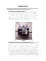
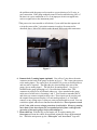
by USER MANUAL FIRMWARE VERSION 1.4 www.aeroforcetech.com Made in the USA! Patent Pending WARNING Vehicle operator should focus primary attention to the road while using the Interceptor. The information provided by this device should be observed as part of a normal sequence of observations performed in the operation of the vehicle, as with any gauge or other instrumentation. Interceptor settings should be changed only during conditions when it is safe to do so. Focusing on the road should be the primary concern of the driver. Aeroforce Technology shall not be held liable in any way for any incidental or consequential damages to the vehicle, driver, passengers, and or other involved parties or property occurring while using the Interceptor scan gauge. Aeroforce Technology shall not be liable for technical or editorial errors or omissions made herein, nor for incidental or consequential damages resulting from the furnishing or use of this manual. Aeroforce Technology, Inc. reserves the right to make changes to this document and the product described without notice. Copyright 2005-2006 Aeroforce Technology, Inc. All rights reserved. 2 INSTALLATION Read these instructions thoroughly before installation. SRT-4 owners, be sure to read your vehicle specific notes on page A3 at the end of this manual. 1. Make sure the car’s ignition is turned off. 2. Run included 5’ main cable, and three wire mini cable, from the OBD2 connector (do not plug in yet) to the location of the Interceptor(s). The Interceptor will fit in any 2 1/16” or 52mm gauge pod, or can be mounted in a custom fashion anywhere within 5 feet of the OBD2 connector. The OBD2 connector is located under the dash on either side of the steering column. 3. Plug both cables into the back of the Interceptor. See figure 1. Press the Interceptor(s) into the gauge pod or mounting hardware. Figure 1 4. Plug the main cable connector into the OBD2 connector. See figure 2. The data, ground, and power on certain vehicles such as the Dodge SRT-4, come from this connector. 5. Connect 3 wire mini connector power. If required*, connect separate red power wire, which exits the middle of the 3 wire mini cable as shown in figure 1, to a switched 12v line or circuit in the vehicle. These circuits are commonly known as “accessory” circuits because they are only “hot” when the ignition is turned on. A recommended way of doing this step is to use a product called an “Add a Circuit”, made by Littelfuse, available at most car parts outlets. These kits, which sell for under $10, allow you to easily use an existing circuit in the fuse block to power an add-on accessory such as the Interceptor without the need to cut or splice any wires. The use of this kit is highly recommended, as most of 3 the problems with the gauge can be traced to a poor selection of a 12v wire, or poor connection. If the gauge randomly turns off and on while driving, 90% of the time it is a poor connection to 12v or an improper circuit was tapped into, such as a signal wire to the instrument panel. *This power wire is not needed on all vehicles, if your cable has this separate red wire in the center of the 3 wire mini connector it needs to be connected as described above. Most GM vehicles made through 2006 require this connection. Figure 2 6. Connect the 0-5v analog inputs (optional). You will see 3 pins above the main connector on the back of the gauge as shown in figure 1. The 2 outer pins connect to the analog inputs. The center pin is for switched 12v power as described above and may not be required. The right side pin, when looking at the rear of the gauge, goes to analog input 1. The left pin is for analog input 2. See figure 1. Included in the gauge packaging is a 3 wire cable that connects here. This connector is not keyed so it will attach either way. Once attached to the gauge, make note of which wire is for analog 1 and 2. You’ll need to remember this if and when you connect a signal to these wires. These inputs can be used to read the outputs from pressure senders, A/F ratio analog outputs, 2 or 3 bar MAP sensors, or any voltage up to 5v that you want to monitor and/or record. You can scale these signals with a menu function described below. These inputs are rated for 0-5 volts, with an over-voltage protection circuit built in. However, running more than 6v into these inputs for an extended period of time could effect the operation of the entire gauge, and possible damage it. 7. Turn vehicle on. With the key on and engine off, or engine running, the Interceptor will scan the vehicle for supported parameters from a predetermined list. While the unit powers up, the “Interceptor” and “AeroForce” logo will 4 appear on the display. This only takes a few seconds. Please note that dual Interceptor units may power up sequentially (one at a time) and may take up to 15 seconds to scan the vehicle. If the vehicle supports a parameter on the list, the Interceptor will see this and allow you to display it. See page A1 of these instructions for the list of parameters supported by the Interceptor. Remember that not all parameters are supported by every vehicle, so don’t expect to see all of them on the Interceptor you install in your vehicle. If the vehicle and the Interceptor support the parameter, you will have access to it. Dual units on vehicles that are powered by the OBD2 port may not power up at exactly the same time. OPERATION 1. SCANNING. Once the Interceptor has been installed, with the vehicle on, you will see an upper and lower field containing a description and parameter value. The right button will change the upper parameter field, the left button the lower. One quick push of the button will toggle to the next parameter. Holding the button down will trigger the unit to quickly scroll through the available parameters until the button is released. Included in the list of parameters is instantaneous fuel economy, calculated horsepower, and both the analog 1 and analog 2 inputs. Fuel economy and horsepower will be available on only those cars using a Mass Air Flow sensor. 2. MENU. Pressing both buttons at the same time will take you to a menu screen. Here you will have eight choices. Use the left button to toggle down to the desired choice. The current selection will be highlighted. Push the right button to select this choice and proceed to the associated screen. You will initially see four menu selections, continuing to scroll down will bring up a new list of 4 more options, with 4 more to follow. Continuing beyond the third group of 4 will bring you back to the beginning. Choices are: a) SCAN. This is the standard mode of operation for the unit and the default mode when powered up. In this mode the unit is scanning and displaying data. b) RECORD. Upon selecting record, the unit will return to normal scan mode except the first letter of each field description will be replaced with a square block to indicate that record is active. You may notice that the gauge is scanning much faster in this mode. Once the throttle position reaches 60% or higher the unit will automatically start recording the displayed data for approximately 45-60+ seconds. When recording begins, the display colors will invert as an alert. The recorded file will be saved for replay until record is selected again and the proper record conditions are met. The new file will overwrite the old. The Interceptor will maintain the file even when powered 5 c) d) e) f) g) h) i) down. If in record mode, you wish to return to normal scan mode, access the menu screen and select record again. This will disable it until selected again via the menu. Recording fuel economy will slow down the data rate as is not recommended if speed is important. PLAY. Once play is selected the Interceptor will return to the normal scan screen but will show the first frame of a recorded log. You will notice the field descriptions flickering to indicate playback mode is in effect. Pushing the right button will toggle forward to the next frame in chronological order, the left button will toggle backwards, or to the very last frame if done at the beginning of the file. Holding either button down will quickly scroll through the data until the button is released. The backlight will flash every time a new frame is displayed. In other words, push a button once and the light will blink once. Hold a button down and the light will blink quickly as each new frame is displayed. Play will not be selectable if the record buffer is empty. DISPLAY DTC’s. Selecting this mode will instruct the Interceptor to acquire and display any diagnostic trouble codes stored in the vehicle’s computer memory. See page A2 for a list and explanation of these codes. CLEAR DTC’s. This selection will instruct the Interceptor to clear the vehicle computer of its stored trouble codes. Be sure to make note of any code before clearing it. INVERT. This menu option inverts the colors on the display. If the display currently has a black background with blue characters for example, inverting will make it blue with black characters. A dark background is called a negative image, and is ideal for low light situations such as driving at night. A light colored or white background is called a positive image, and is easier to read in bright sunlight. DIMMER. Selecting “Dimmer” will take you to a new screen with a brightness value displayed, between 1-3. 1 is the dimmest, 3 the brightest. Using the left button you can raise this value until you reach 3 after which it will restart back at 1. Once the desired brightness is reached press the right button to return to the menu screen. DATA RATE. Choosing scan rate allows you to adjust the speed in which the display will update. When selected, a number from 1 to 6 will appear, the higher the value the slower the scan rate. The left button can be used to alter this value. Select the new value by hitting the right button, which will send you back to the main menu. PERFORMANCE. This selection will allow you to measure 0-60 mph (100 Km/hr in the metric version), 1/8 mile and ¼ mile performance with speed. Selecting this option will take you to a screen saying “vehicle must be at 0 mph before starting”. This indicates that the timer will not start until the vehicle is fully stopped, and starts moving. Once the vehicle starts moving, the screen colors will invert and the timing will commence. Once the ¼ mile mark is reached a summary screen will appear, showing ¼ time and speed, 1/8 mile time and speed, and 0-60 time. If you do not run a full ¼ mile, the measurement will eventually time out and indicate the 1/8 mile stats as well as 0-60 once the timeout occurs. This timeout may take several minutes so it’s 6 best to coast a full ¼ mile even if all you want is 0-60 or 1/8 mile times. When finished viewing the results hit the right button to return to the main menu. These statistics can be viewed again by choosing the “Statistics” menu option described below. Please note that this measurement’s accuracy is dependent upon the accuracy of the speed signal. If the vehicle has non-stock sized wheels or the rear axel ratio has been changed, and the vehicle’s speed sensor has not been recalibrated or the PCM reflashed accordingly, the accuracy of these measurements will be effected. Another way of stating this is that if your speedometer is inaccurate, so will be these measurements. In addition, wheel spin will effect 1/8 and ¼ mile e.t.’s, giving inaccurately lower times. j) STATISTICS. This menu option, once selected, will display the results of the previous performance measurement run. Only the last run will be stored, and the data overwritten once another run is made. Make a note of this data if it is needed for permanent reference. k) SHIFT LIGHT. This selection will allow you to enter an RPM value that once reached will turn on the bright LED shift lights. Enter a 4 digit value, starting from left to right. Hitting the right button will cause the digit above the cursor to change from 1-9. Once the correct digit is entered, hit the left button and repeat until all 4 digits are correct. After entering the last digit you will go back to the menu. The “data rate” must be set to “1” for the shift light to be activated to ensure accuracy. Because of the nature of some data buses, you may see a false, occasional blink of these lights when driving with the light activated. This is due to an erroneous rpm signal received by the gauge. These will be infrequent and random, and are not an indication of a faulty gauge. Changing the “data rate” to something other than “1” will completely disable the shift light, as will setting it to a value of “0000”. Turning off the shift light by setting it to “0000” will speed up the #1 data rate as well as record rate by another 30% when extremely fast data acquisition is needed. l) HORSEPOWER ADJUSTMENT. This choice allows you to enter a correction factor for the horsepower parameter and the MPG parameter. This one correction factor applies to both. These parameters are available on those cars using a factory Mass Air Flow sensor. Net horsepower and fuel mileage can be closely calculated by knowing the mass air flow value. However, since each car is slightly different in efficiency, this calculation can be adjusted if the exact peak hp is known after being run on a dyno, or the MPG reading needs adjustment. For example, if the gauge indicates 300 hp, and the net hp (not rear wheel hp) is determined to be 315, you can enter a correction factor of 1.05 (adding 5%). This is done by selecting this menu option, and entering this factor. There is no decimal shown, so you will be entering this value as a three digit number. For example, 1.05 will be entered as 105, 0.95 will be entered as 095 (subtracting 5%). Likewise, if fuel mileage reading is known to be off by 5%, say the gauge is reading 5% low, enter a correction the same way (105). As with the shift light entry field, you will use the left button to change the digit above the cursor. Hitting the right 7 button will move the cursor to the next digit. After the last digit is entered you will return to the main menu. The factory default value is 100, representing 1.00, or no correction factor. Also, if the MAF sensor has been recalibrated or replaced with one sized differently, this correction factor can be used to compensate for this change. For example, if the original MAF is rated at 60lb/min, and the new one is 100 lb/min, find the increase in size by dividing 100 by 60 = 1.6667. This number, entered as 16667, would be the correction factor you’d add here. It doesn’t matter how the sensor is rated, kg/hr, grams/sec, etc., the same method is used. m) Analog 1. This selection allows the user to enter a conversion for this 0-5v input, which uses the right pin of the three pin connector. To read raw volts, enter “1” for slope, and “0” for intercept. This is the default setting as well. For example, say you want to input the analog output of a wide band O2 sensor kit. You know from the kit’s documentation that the output is scaled such that 0v=10 A/F ratio, and 5v = 20 A/F ratio. The conversion would then be a slope of 2, with an intercept of 10. In other words, voltage multiplied by 2 plus 10 would equal A/F ratio. In this example, a voltage of 5 would result in 5*2+10 equals 20 A/F ratio. Another common use for these analog inputs are for MAP sensors. The GM 3 bar MAP is a common sensor used to measure high levels of boost. The conversion for this sensor would be V*914.8, or a slope of 9, intercept of -14.8. The slope can be tweaked if the sensor does not read “0” with the key on, engine off. Our personal 3 bar MAP had a slight zero offset that we adjusted by changing the intercept value. These inputs use a 10 bit A/D device, and are highly accurate to the .01 volts. You will only see a resolution of 0.1 volt displayed, but the calculations are based on the full 10 bit conversion and are not rounded off for higher accuracy. n) Analog 2. Same as Analog 1. Uses the left pin of the three pin connector. On the SRT-4 versions only, if the gauge is not returned to scan mode after 10 minutes the menu will time out and return to normal scan mode on its own. If the vehicle is shut off while the menu is displayed, the unit will stay on for the remaining 10 minutes before timing out, returning to scan, and then turning itself off. Powering down The Interceptor will automatically shut itself off within seconds of the ignition being turned off. Dual SRT-4 units may not power down at the exact same time. Non-OBD2 powered gauges, both single and dual, may also momentarily turn on when the vehicle is locked or unlocked. 8 Non-Volatile Memory The Interceptor does not require batteries or a continuous power source to maintain its memory. This means that your data will not be lost if you disconnect the vehicle battery or disconnect the cable from the OBD2 port. Precautions Unplug the Interceptor before disconnecting the battery or performing engine work to prevent damage to the unit. The Interceptor’s display is designed to operate continuously at temperatures up to 122 deg. F (50 deg. C). The display may appear “washed” out for a minute or so if exposed to direct sunlight in hot climates after the car has been parked for an extended period of time. If the gauge is mounted in such a way that it can be exposed to direct sunlight, such as on top of the dash, you may want to consider a windshield shade, or unplugging the display for a minute or two until it and the car cool off a little. If you gauge’s cable did not come with a separate power wire, unplug the gauge if the vehicle will not be used for more than 5 days. Care If the face of the Interceptor needs cleaning, use light pressure with a non-scratching material such as a pre-moistened micro-fiber material made for plastic sunglass lenses. The plastic lens will scratch if anything abrasive is used on it. 9 Limited Warranty Aeroforce Technology warrants this product and its accessories against defects in material and workmanship for a period of 180 days from the date of purchase. Aeroforce Technology will repair or replace this product with new or refurbished products or parts, at Aeroforce’s option, free of charge in the USA. This warranty extends only to the original purchaser. A purchase receipt or other proof of date of original purchase from and authorized dealer (including Aeroforce Technology) is required on order to have warranty service performed. Before sending an Interceptor back for warranty service, you must obtain a Return Materials Authorization number from Aeroforce Technology. This can be done by emailing [email protected] including a description of the problem and date/place of purchase. An RMA number will be returned to you as well as a return address. This warranty covers failures due to material or workmanship defects only. This warranty does not cover cosmetic damage or damage due to accident, misuse, abuse, negligence, commercial use, acts of God, or modifications of, or any part of the product, including accessories. 10 A1A-GM Supported Parameters (PID’S) 1. INTAKE AIR- Intake Air Temperature 2. COOLANT TEMP- Engine Coolant Temperature 3. TRANS TEMP- Transmission Temperature 4. RPM- engine Revolutions Per Minute 5. MAF SENSOR LB/M- Mass Air Flow (lbs/min) 6. MAF FREQUENCY- raw Mass Air Flow sensor output (frequency) 7. MANIFOLD PSI- Manifold Air Pressure (psi)* 8. THROTTLE POS PCT- Throttle Position percentage (0-100%) 9. THROTTLE VOLTS- Throttle Position sensor output (0-5 volts) 10. MILES PER HOUR- Miles Per Hour 11. KNOCK RETARD- Knock Retard (degrees) 12. IGNITION ADVANCE- ignition timing advance 13. PULSE WIDTH- injector #1 pulse width (4&6 cylinder engines) 14. SHORT TRIM B1-short term fuel trim bank#1 15. SHORT TRIM B2-short term fuel trim bank#2 16. LONG TRIM B1-long term fuel trim bank#1 17. LONG TRIM B2-long term fuel trim bank#2 18. OXYGEN SENSOR B1-O2 bank 1 sensor in millivolts 19. OXYGEN SENSOR B2-O2 bank 2 sensor in millivolts 20. RUN TIME MINS- engine run time is tenths of seconds since last engine start 21. BATTERY VOLTAGE- Alternator/battery output voltage 22. IAC POSITION- Idle Air Control counts (position of Idle Air Control valve) 23. PULSE WIDTH B1-injector Pulse Width for bank 1 (8 cylinder engines) 24. PULSE WIDTH B2-injector Pulse Width for bank 2 (8 cylinder engines) 25. ENGINE LOAD-calculated Engine Load (0-100%) 26. ENGINE OIL PRESSURE (some 8 cylinder engines) 27. Miles Per Gallon- instantaneous fuel economy 28. Calculated net horsepower 29. Analog 1 – analog input #1. 30. Analog 2 – analog input #2 31. INTAKE AIR 2 – Intake Air Temp. downstream of intercooler (some supercharged applications). *Will read in PSI (pounds per square inch) whether in vacuum or under boost (factory forced induction applications). Normal range is approximately -9 psi at idle. 11 A1B- Ford Supported Parameters (PID’S) 1. INTAKE AIR- Intake Air Temperature 2. INTAKE AIR TEMP. 2 (intercooled applications) 3. COOLANT TEMP- Engine Coolant Temperature 4. TRANS TEMP- Transmission Temperature 5. RPM- engine Revolutions Per Minute 6. MAF SENSOR LB/M- Mass Air Flow (lbs/min) 7. MAF COUNTS- raw Mass Air Flow sensor output (counts) 8. MANIFOLD PSI- Manifold Air Pressure (psi)* 9. THROTTLE POS PCT- Throttle Position percentage (0-100%) 10. THROTTLE VOLTS- Throttle Position sensor output (0-5 volts) 11. MILES PER HOUR- Miles Per Hour 12. KNOCK RETARD- Knock Retard (degrees) 13. IGNITION ADVANCE- ignition timing advance 14. PULSE WIDTH- injector #1 pulse width (4&6 cylinder engines) 15. SHORT TRIM B1-short term fuel trim bank#1 16. SHORT TRIM B2-short term fuel trim bank#2 17. LONG TRIM B1-long term fuel trim bank#1 18. LONG TRIM B2-long term fuel trim bank#2 19. OXYGEN SENSOR B1-O2 bank 1 sensor in millivolts 20. OXYGEN SENSOR B2-O2 bank 2 sensor in millivolts 21. RUN TIME MINS- engine run time is tenths of seconds since last engine start 22. BATTERY VOLTAGE- Alternator/battery output voltage 23. IAC POSITION- Idle Air Control counts (position of Idle Air Control valve) 24. PULSE WIDTH B1-injector Pulse Width for bank 1 (8 cylinder engines) 25. PULSE WIDTH B2-injector Pulse Width for bank 2 (8 cylinder engines) 26. ENGINE LOAD-calculated Engine Load (0-100%) 27. ENGINE OIL PRESSURE - (some 8 cylinder engines) 28. Miles Per Gallon – instantaneous fuel economy 29. Calculated net horsepower 30. Analog 1 – analog input #1 31. Analog 2 – analog input #2 *Will read in PSI (pounds per square inch) whether in vacuum or under boost (factory forced induction applications). Normal range is approximately -9 psi at idle. 12 A2-DIAGNOSTIC TROUBLE CODES (DTC’s) The Interceptor will display the code in the hex format of XXXX. See Table 1 below for explanation and interpretation of these Interceptor codes. Replace with this… ↓ If the first hex digit is this → 0 P0 Powertrain codes – SAE defined 1 P1 “ “ – manufacturer defined 2 P2 “ “ – SAE defined 3 P3 “ “ – jointly defined 4 C0 Chassis Codes – SAE defined 5 C1 “ “ – manufacturer defined 6 C2 “ “ – manufacturer defined 7 C3 “ “ – reserved for future 8 B0 Body Codes – SAE defined 9 B1 “ “ – manufacturer defined A B2 “ “ – manufacturer defined B B3 “ “ – reserved for future C U0 Network Codes – SAE defined D U1 “ “ – manufacturer defined E U2 “ “ – manufacturer defined F U3 “ “ – reserved for future TABLE 1 For example, if code 0107 is returned, replace the first “0” with P0, resulting in code P0107. Looking up this code reveals: “ P0107-Manifold Absolute Pressure/Barometric Pressure Circuit Low Input” There are many resources that fully explain these codes including the specific vehicle shop manual, web sites, as well as automotive self-help guides. A list of power train diagnostic trouble code explanations can be found on our web site at 13 http://www.aeroforcetech.com/files/Partial_list_of_diagnostic_trouble_codes.txt The http://www.aeroforcetech.com/files/Partial_list_of_diagnostic_trouble_codes.txt. web site www.troublecodes.net/OBD2/ is another source of explanation for these codes. For a description of the SRT-4 or Dodge codes, visit http://www.aeroforcetech.com/files/SRT-4_DTC_s.rtf. http://www.aeroforcetech.com/files/SRT 14 A3-TIPS AND VEHICLE SPECIFIC NOTES ’04 Pontiac Grand Prix: A common mount for the Interceptor is in the top left vent next to the steering wheel. If mounted here, hot air cannot be blown directly on the unit for extending periods of time. Insulation should be placed behind the Interceptor if hot air is blown through this vent when the heater is on for example. 4800 Vortec: Throttle voltage reads “0” all the time. It is not a supported parameter on this motor. Some parameters are not supported by all vehicles but they may still be displayed as a “dummy” value in place of a real one. Certain manual transmission cars will display a false transmission temperature, and some V8’s will display an erroneous oil pressure for example. These “dummy” values may be obviously incorrect, or may look normal at first but never change. ’97 Pontiac Grand Prix: Ignition advance will be displayed as a negative number. 2000-2001 Grand Prix: There has been a couple reports of the Pass Key III system rejecting the keys when this gauge is plugged in when the car is started in extremely cold temperatures (below 20 degrees F). Therefore it is recommended to unplug the gauge before starting these cars in these extremely cold temperatures, and plugging it back in a few seconds after the car is started. There is no need to disconnect the power wire though. 2000-2003 full size GM SUV’s and Corvette: Owners my find that scan speeds need to be lowered to setting 3 or higher to prevent false error messages on the vehicles instrument panel. These vehicles have extremely high data volumes with slower than desirable bus hardware. ‘96/’97 V8 GM trucks: A smaller set of parameters are supported for these vehicles. You may only see 9-10 as opposed to 20+ for later years. Saturn Ion Redline/Chevy Cobalt SS: You should have received a unique version of the Interceptor specific to your vehicle. These versions display 2 parameters not shown on the page A1 list. These are: 1. Intake Air2 temp: This is the temperature of the air exiting the intercooler. This is a very useful tuning aid in determining the efficiency of the intercooler. The lower this temperature the better. 2. SC inlet pressure: This indicates the pressure at the inlet of the supercharger. It is the difference between the barometric pressure and the absolute pressure at the supercharger inlet. The higher the value, the more restrictive the intake/air filter which is especially useful to know under boost. This can be used to determine the effectiveness of aftermarket cold air intakes. If the value of this parameter drops at wide open throttle after installing a new intake kit, the restriction has been reduced and more power should be achieved. SRT-4: This unit does not require a separate connection to power, but otherwise operates identically to the GM and Ford versions. It does not 15 support as many of the manufacturer specific parameters, however. It will also not display fuel economy or calculate horsepower because a Mass Air Flow sensor is necessary to accurately determine these parameters, which the SRT-4 does not have. The analog inputs and shift light all work as described. Chrysler also uses a slightly different method of clearing DTC’s (Diagnostic Trouble Codes). The clear a DTC, the ignition must be turned on, with the engine off. Once the “Clear DTC” command is chosen from the menu, the check engine light will turn off once the engine is started again. Our website has a list of Chrysler DTC’s at: http://www.aeroforcetech.com/files/SRT-4_DTC_s.rtf. http://ww SRT-4 Dual Units: Each gauge will have a separate part number, in the form of SRx0x106 and SRx0x108. The ones that end in “6” will be fully functional, the other will not have the performance timer function, nor will it log at 10 samples per second as the “6” will, but rather at 2-3 times per second. Both of these steps were necessary due to limitations of the SRT-4 bus. It simply cannot handle the high rate of acquisition that two gauges running full speed produce. If you run either gauge at the #1 data rate (fastest), the other should not be run lower (faster) than #3. Both can be set to #2 or higher (slower). Knowing this, set the “6” gauge for parameters that require monitoring at a high data rate, such as knock retard or ignition advance. This way you will catch any transient or quickly changing values. Slower changing parameters such as intake air temp or engine coolant temp can be logged on the “8” gauge at 2-3 times per second without missing anything important. 16