1
OS-9 for 68K Processors
OEM Installation Manual
Version 3.3
w w w. r a d i s y s . c o m
Revision B • July 2006
Copyright and publication information
Reproduction notice
This manual reflects version 3.3 of OS-9 for 68K.
Reproduction of this document, in part or whole, by any means,
electrical, mechanical, magnetic, optical, chemical, manual, or
otherwise is prohibited, without written permission from RadiSys
Microware Communications Software Division, Inc.
The software described in this document is intended to
be used on a single computer system. RadiSys
Corporation expressly prohibits any reproduction of the
software on tape, disk, or any other medium except for
backup purposes. Distribution of this software, in part
or whole, to any other party or on any other system
may constitute copyright infringements and
misappropriation of trade secrets and confidential
processes which are the property of RadiSys
Corporation and/or other parties. Unauthorized
distribution of software may cause damages far in
excess of the value of the copies involved.
Disclaimer
The information contained herein is believed to be accurate as of
the date of publication. However, RadiSys Corporation will not be
liable for any damages including indirect or consequential, from
use of the OS-9 operating system, Microware-provided software,
or reliance on the accuracy of this documentation. The
information contained herein is subject to change without notice.
July 2006
Copyright ©2006 by RadiSys Corporation
All rights reserved.
EPC and RadiSys are registered trademarks of RadiSys Corporation. ASM, Brahma, DAI, DAQ, MultiPro, SAIB, Spirit, and ValuePro are
trademarks of RadiSys Corporation.
DAVID, MAUI, OS-9, OS-9000, and SoftStax are registered trademarks of RadiSys Corporation. FasTrak, Hawk, and UpLink are
trademarks of RadiSys Corporation.
†
All other trademarks, registered trademarks, service marks, and trade names are the property of their respective owners.
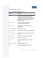
Ta bl e o f C on t e n ts
Chapter 1: Getting Started
12
12
14
14
15
17
18
20
21
22
23
25
27
29
34
Developing a Plan
The Host System Hardware
The Host System Software
The Target System Hardware
Pre-Porting Steps
The Make Utility
Common File Name Suffixes
Checking the Contents of the Distribution
Structure of the Distribution Package on the Host System
MWOS/OS9/SRC Directory Structure
MWOS/OS9 Directory Structure
OS-9 Macro Routines
MWOS/OS9/SRC/IO Directory Structure
MWOS/OS9/SRC/ROM Directory Structure
Additional Reference Materials
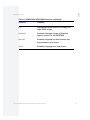
Chapter 2: Porting OS-9 for 68K
38
39
40
42
43
45
11
37
Getting Started
Understanding the OS-9 for 68K Booting Process
Step 1: Power Up the ROMbug Prompt
Step 2: ROMbug Prompt to Kernel Entry
Step 3: Kernel Entry Point to $ Prompt
The Four Porting Steps
Chapter 3: Step One: Porting the Boot Code
OS-9 for 68K Processors OEM Installation Manual
49
3
50
50
51
52
52
53
57
58
59
60
60
63
64
66
67
68
71
72
72
77
78
79
80
81
82
96
96
97
97
99
100
101
4
Introduction
About the Boot Code
How to Begin the Port: The Boot Code
Testing the Boot Code
ROM Image Versions
Component Files of the ROM Image
The Defsfile File
The Oskdefs.d File
The Systype.d File
The ROM Configuration Values
Target Specific Labels
Target Configuration Labels
CPUTyp Label and Supported Processors
Low Level Device Configuration Labels
Target System Memory Labels
Example Memory Definitions
The Vectors.a File
The Boot.a File
Steps Boot.a Goes Through to Boot the Kernel
Memory Search Explanations
The RAM Search
The Special Memory Search
The Patch Locations
The ioxxx and ioyyy Files
I/O Driver Entry Points
The Sysinit.a File
The SysInit Entry Point
The SInitTwo Entry Point
The UseDebug Entry Point
The Syscon.c File
The initext.a File
Putting the ROM Together
OS-9 for 68K Processors OEM Installation Manual
Chapter 4: Step Two: Bringing Up the Kernel and Console I/O
104
106
108
110
111
113
114
116
117
118
121
103
Preparing the First Stage OS-9 Configuration
Creating the Init Module
SCF Device Descriptor Macro Definitions
Creating a Console I/O Driver
Preparing the Download File
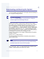
Downloading and Running the System
Downloading and Running the System
Cold Part of Kernel
The coldstart() Routine
Cold2(): Bringing Up the System the Rest of the Way
Debugging Hints
Chapter 5: Step Three: Creating Customized I/O Drivers and Finishing the
Boot Code
123
124
125
126
127
128
128
129
130
131
133
134
135
136
138
139
141
143
Guidelines for Selecting a Tick Interrupt Device
OS-9 Tick Timer Setup
Tick Timer Activation
Real-Time Clock Device Support
Microware Generic Clock Modules
Tickgeneric Support
Ticker Support
Real-Time Clock Support
Using Generic Clock Modules
Philosophy of Generic Clock Modules
Automatic System Clock Startup
Debugging Clock Modules on a Disk-Based System
Debugging Clock Modules on a ROM-Based System
Creating Disk Drivers
Testing the Disk Driver
Creating and Testing the Disk Boot Routines
Testing the CBoot Disk Boot Module
OS-9 for 68K Processors OEM Installation Manual
5
144
Further Considerations
145 Completing the System
Chapter 6: Step Four: Testing and Validation
148
149
150
151
152
153
154
155
147
General Comments Regarding Testing
Kernel Tests
Serial I/O (SCF) Tests
Disk I/O (RBF) Tests
Clock Tests
Final Tests
System Configuration Checkout
A Final Note
Chapter 7: Miscellaneous Application Concerns
157
158 Disk Booting Considerations
158
Boot Drivers Supporting Variable Sector Size
161
Bootstrap File Specifications
162
Making Boot Files
162
Bootstrap Driver Support
164 Soft Bus Errors Under OS-9
Chapter 8: OS-9 Cache Control
166
167
167
169
171
174
175
177
178
179
6
165
OS-9 Cache Control
System Implementation
Install Cache Operations
Default SysCache Modules
Caching Tables
Custom Configuration for External Caches
M$Compat2 Bit Fields
ROM Debugger and Caches
Peripheral Access Timing Violations
Timing Loops
OS-9 for 68K Processors OEM Installation Manual
180 Building Instructions in the Data Space
181 Data Caching and DMA
181
Indication of Cache Coherency
183 Address Translation and DMA Transfers
Chapter 9: RBF Variable Sector Support
186
188
190
191
192
194
RBF Device Drivers
Converting Existing Drivers to Use Variable Sector Size
RBF Media Conversion
Benefits of Non-256 Byte Logical Sectors
Bootstrap Drivers
RBF Disk Utilities
Appendix A: The CBoot Technology
196
197
201
205
195
Introduction
The CBOOT Common Booters
CBOOT Driver Entry Points
CBOOT Library Entry Points
Appendix B: Trouble Shooting
236
237
239
241
243
246
185
235
Introduction
Step 1: Porting the Boot Code
Step 2: Porting the OS-9 for 68K Kernel and Basic I/O
Coldstart Errors for the Atomic Versions of the Kernel and IOMan
Setting Up the DevCon Descriptor Field for the Sc68681 Serial Driver
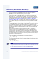
Searching the Module Directory
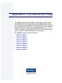
Appendix C: Low-level Driver Flags
249
250 Flags for io2661.a
251 Flags for io6850.a
252 Flags for io68560.a
OS-9 for 68K Processors OEM Installation Manual
7
253
254
255
257
258
Flags for io68562.a
Flags for io68564.a
Flags for io68681.a
Flags for io68901.a
Flags for ioz8530.a
Appendix D: SCSI-System Notes
259
260 OS-9 for 68K SCSI-System Drivers
260
Hardware Configuration
261
Example One
261
OMTI5400 Controller
261
Fujitsu 2333 Hard Disk with Embedded SCSI Controller
261
Host CPU: MVME147
262
Software Configuration
263
Example Two
264
Example Three
Appendix E: Using the OS-9 for 68K System Security Module
268
269
269
270
274
274
275
275
277
279
283
285
285
8
267
Memory Management Units
Hardware/Software Requirements
Versions of SSM040
Configuring SSM for MC68451 Systems
Adding SSM to the OS-9 Bootfile
Step One: Create a New Init Module
Step Two: Create a New Bootfile
Step Three: Test SSM Operation
Creating a System Security Module
SSM Module Structure
Hardware Considerations
Complete Source Listing
Customized 68020 protection module
OS-9 for 68K Processors OEM Installation Manual
Appendix F: Example ROM Source and Makefiles
298
299
302
304
306
308
310
312
314
316
318
297
defsfile
systype.d
sysinit.a
syscon.c
rombug.make
rom.make
rom_common.make
rom_serial.make
rom_port.make
rom_image.make
bootio.c
Index
OS-9 for 68K Processors OEM Installation Manual
323
9
10
OS-9 for 68K Processors OEM Installation Manual
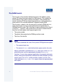
C h a p t e r 1 : G e t t i n g Sta r t e d
This chapter includes the following topics:
•
Developing a Plan
•
The Make Utility
•
Common File Name Suffixes
•
Checking the Contents of the Distribution
•
Structure of the Distribution Package on the Host System
•
OS-9 Macro Routines
•
Additional Reference Materials
Developing a Plan
You have chosen OS-9 for 68K, the world’s leading real-time operating
system for Motorola 68000-based real-time and embedded systems. Now
we hope you find it easy to actually port OS-9 to your new target system.
But to do that, it is important you take a little time to develop a plan for
accomplishing this.
If you have not already realized it, you need to determine what your
development environment will be. This includes such things as:
•
What kind of host development system you use to edit and re-compile
OS-9 source files.
•
What additional development equipment is needed to test your port of
OS-9 on your target and how this equipment is connected to your host
development system. This is closely tied to the mode of operation you
use to port the OS-9 Boot ROMs to your target.
We strongly suggest you read through at least the first three chapters of
this manual before attempting to start the port. This should give you a good
perspective on what is required to accomplish the port, and should help
you develop a better plan.
Before installing OS-9 for 68K, you need to understand two terms:
host system
The development system used to edit and
re-assemble OS-9 source files.
target system
The system on which you intend to port
OS-9.
The Host System Hardware
The host system can be any of the following:
12
•
A 68000 family-based computer with at least 2MB RAM and OS-9 for
68K
•
Any 286 PC (or greater) running DOS
OS-9 for 68K Processors OEM Installation Manual
1
Getting Started
Note
The installation procedure may vary at times according to the type of
development system being used. This is noted when important.
You also need the following on the host system:
•
A hard disk. The directory structure of the files supplied in the
distribution package assume the host system has a hard disk. This is for
storage capacity, not speed. If you use floppy disks, you must rearrange
and edit many of the source files and make files. Microware does not
guarantee OS-9 can be rebuilt on a host system with only floppy disks.
•
Extra RS-232 serial ports for communicating with the target system,
PROM programmer, and any PROM or microprocessor emulation
systems you choose to use.
•
A PROM programmer that can accept data from the host system
because you have to make one or more PROMs. Many commercial
PROM programmers and emulators, interfacing through RS-232 serial
links, accept programming data in the form of Motorola standard
S-records. S-records are simply binary data, usually object programs,
converted to ASCII hex characters in a standardized format.
Note
The Microware-provided software (the binex and exbin utilities) can
convert data to S-record format if necessary.
•
A 68000 emulation system (optional). If possible, the emulator should
have at least 128K overlay memory. The emulator provides handy
real-time debugging facilities, and the overlay memory is a convenient
substitute for making ROMs during the testing process.
OS-9 for 68K Processors OEM Installation Manual
13
•
PROM emulators (optional). This type of device is most useful with a
target known to be functional and an existing resident debugger that
does not have downloading capability or when no debugger exists and
no emulation system is available.
The Host System Software
The OS-9 Developer’s Kit is a source release for Original Equipment
Manufacturers (OEMs) designed to be installed on a host system. Use of
the OS-9 Developer’s Kit requires a separately available toolkit designed for
the host system. The types of toolkits available are:
•
Hawk for Windows 95/NT
•
A resident toolkit for OS-9 systems
Each of the above toolkits includes the Ultra C compiler, assembler and
linker, and all utilities necessary to rebuild OS-9.
The Target System Hardware
The target system should consist of the following hardware:
•
A 68000 family CPU.
•
At least 128K RAM; 512K is recommended.
•
At least 64K ROM capacity or an emulator with 64K of overlay memory;
however, 128K is required if you plan to use ROMbug. The 64K ROM is
for convenience in bringing up OS-9. If the system is disk-based, the
eventual target system can use as little as 32K for a boot ROM.
•
Two serial I/O ports; one for a terminal and one for communications with
the host system. These are only required for the porting process.
•
Any other I/O devices OS-9 must eventually support (optional). These
are not used in the initial installation steps.
An existing debugger on a functional target can be used in lieu of an
emulation system for debugging the OS-9 boot ROMs until ROMbug is
functional enough to be used. In this type of configuration, the OS-9 boot
14
OS-9 for 68K Processors OEM Installation Manual
1
Getting Started
ROM image can be built to run from RAM. However, some mechanism
must exist to get the image into RAM, either by downloading through a
serial port (using the existing debugger) or by accessing memory from
another processor in the same system (a master CPU in a VMEbus
system, for example).
Pre-Porting Steps
Before you port OS-9 for 68K:
•
Make sure the hardware works. It is difficult to simultaneously debug the
hardware and the software. If the target system is an untested
prototype, use the assembler to make a simple stand-alone test ROM
that just prints a message on a terminal to verify basic hardware
functionality. Using emulators and logic analyzers aids in simulation of
hardware and software.
Note
The time invested in writing basic diagnostic software that fully
exercises memory, I/O devices, and interrupts is often well worth it.
•
Hook up the serial ports that link the host to the target system, and, if
possible, test the communications link using existing software that
already runs on your host system.
OS-9 for 68K Processors OEM Installation Manual
15
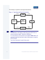
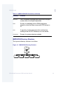
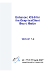
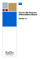
The following is a typical host and target interconnection:
Figure 1-1 Typical Host and Target Interconnection
RS-232
Host
System
Target
System
RS-232
CRT/
Workstation
RS-232
PROM
Programmer
CRT
Optional
RS-232
Note
Use 9600 baud or the highest possible data rate for RS-232 links to
maximize download speed. The default is 9600 baud.
If you are porting to a slow processor (for example, 68000 8 MHz), you
may have to lower the baud rate in order for the processor to keep up
with the transfer.
The X-On/X-Off protocol is used for flow control.
16
OS-9 for 68K Processors OEM Installation Manual
1
Getting Started
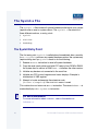
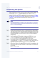
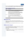
The Make Utility
While you are porting OS-9 for 68K to the target system, you use the make
utility extensively. The OS-9 make utility uses makefiles to re-assemble and
link many major parts of OS-9. Makefiles simplify software creation and
maintenance.
We strongly recommend you use and maintain the makefiles as you port
OS-9. The makefiles for each major subsystem are located in the
subsystem’s highest level directory and are usually named makefile.
More In
fo More
Informatio
n More Inf
ormation M
ore Inform
ation More
-6-
For More Information
Familiarize yourself with the description of the make utility provided in
Using OS-9 for 68K Processors if you are using an OS-9 based host
system.
Knowing how the makefiles work is a key to understanding a port. In order
for the port to fit into your particular hardware configuration, use flags to
conditionalize the code that is assembled/compiled. These flags are fully
explained later in this manual. Customize these makefiles to fit your
hardware configuration.
OS-9 for 68K Processors OEM Installation Manual
17
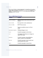
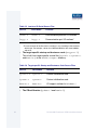
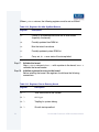
Common File Name Suffixes
Microware uses the following file name suffixes to identify file types:
Table 1-1 File Name Suffixes
18
Suffix
Definition
.a
Assembly language source code.
.c
C language source code.
.d
Definitions (defs) source code (for assembly).
.h
C header file source code.
.i
Microware intermediate code (I-code) files.
.il
Microware intermediate code libraries.
.l
Library files.
.m
Macro files.
.o
Assembly language source from the compiler backend.
.r
Relocatable object code (for linker input), created by the
assembler.
none
Object (binary) files.
OS-9 for 68K Processors OEM Installation Manual
1
Getting Started
Note
In general, OS-9 for 68K does not require file name suffixes. However,
certain utilities, such as µMACS and cc, do require file name suffixes to
determine the mode of operation.
OS-9 for 68K Processors OEM Installation Manual
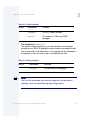
19
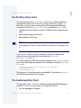
Checking the Contents of the Distribution
You should become familiar with the contents of the distribution package
provided by Microware. Verify it is:
•
Complete
•
The correct version for your host system
The distribution software consists of a set of OS-9 diskettes, discs, or tape
cartridges. Refer to the MWOS directory structure described in this chapter
for the organization of the shipping/development directory structure.
20
OS-9 for 68K Processors OEM Installation Manual
1
Getting Started
Structure of the Distribution Package on the
Host System
The distribution package contains a large number of files comprising the
operating system and its utilities. A few files are source code text files. Most
others are object code files. The files are organized into subdirectories
according to major subsystems (ROM, IO, CMDS, and so forth).
A master directory called MWOS is created. The entire distribution package
file system should be copied intact into this directory structure. We have
assumed you use a hard disk based system with sufficient storage capacity
to contain the entire file system.
Microware has adopted this general directory structure across all of its
product lines. This allows all source products to reside together in a single
directory and provides a means for sharing code across all operating
system products.
Note
The files in the distribution package assume this specific file and
directory organization. They can not assemble and link correctly if the
organization is not correct.
OS-9 for 68K Processors OEM Installation Manual
21
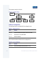
MWOS/OS9/SRC Directory Structure
Taking a closer look at MWOS/OS9/SRC we see:
Figure 1-2 MWOS/OS9/SRC Directory Structure
OS9
SRC
DEFS
IO
MACROS
ROM
SYS
SYSMODS
These directories are as follows:
Table 1-2 MWOS/OS9/SRC Directories
22
Directory
Contains
DEFS
Files of definitions that apply system-wide, or are target
independent. These are both assembler .d and C .h
include files.
IO
Sources for all I/O subsystems including file-managers,
drivers, and descriptors. The file’s subdirectories are
organized by subsystem (detailed below).
IOMAN
Source for the IOMan module (if you purchased a
license for IOMan source), whose functionality was
integral to the kernel in previous releases.
KERNEL
Source for all kernel variants (if you purchased a
license for kernel source).
LIB
Sources for all system and subsystem libraries.
OS-9 for 68K Processors OEM Installation Manual
1
Getting Started
Table 1-2 MWOS/OS9/SRC Directories (continued)
Directory
Contains
MACROS
Files of assembly language macro definitions that apply
system-wide or are target independent.
ROM
Sources for rebuilding all boot ROM components,
except for a few that share source with SCSI drivers in
IO.
SYS
A repository for files and scripts that would end up
residing in the OS-9 SYS directory on a root device.
SYSMODS
Sources for system extension modules.
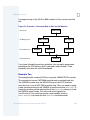
MWOS/OS9 Directory Structure
The top-most directory structure is as follows:
Figure 1-3 MWOS/OS9 Directory Structure
MWOS
OS9
68000
68020
CPU32
MAKETEMPL
OS-9 for 68K Processors OEM Installation Manual
SRC
23
These directories are as follows:
Table 1-3 MWOS/OS9 Directories
24
Directory
Contains
SRC
The source files for the OS-9 drivers, descriptors,
system modules, defs, and macros. It is intended to be
a source directory containing hardware-specific code
written to be reuseable from target to target. It is not
intended to be the repository for final object modules
built from this source, although intermediate object files
may be found within its subdirectories.
MAKETMPL
A directory for common makefile templates (include
files for makefiles). In this release, any templates found
in this directory apply only to makefiles for ISP and
related products.
68000,
68020,
and CPU32
These remaining directories can be thought of as object
directories for target processor architectures or families.
It is in these directories that processor-family-specific
objects are deposited when built, and where
target-specific source code, makefiles, and final objects
reside.
OS-9 for 68K Processors OEM Installation Manual
1
Getting Started
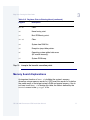
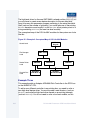
OS-9 Macro Routines
The macros in the SRC/MACROS directory are designed to be useful,
general purpose macros for driver/file, manager/kernel development. Do
not place macros pertaining to specific drivers, for example, in this
directory.
Note
Do not edit these macros. Many varied source files use these macros,
and your changes may have unforeseen consequences to other users.
The following list summarizes each macro’s purpose. If you add any
macros to this directory, please update this list accordingly.
Table 1-4 OS-9 Macros
Name
Description
btf.m
Create branch if true/false instruction sequences, for
situations where Scc instructions are used to
manipulate flags.
ldbra.m
Make a dbra loop using a 32-bit value.
longio.m
Define access methods for devices.
nvram.m
Provides NVRAM access.
OS-9 for 68K Processors OEM Installation Manual
25
Table 1-4 OS-9 Macros (continued)
26
Name
Description
os9svc.m
Make a system call quickly in a driver or file manager.
This is generally useful only for system calls that do
not return parameters (such as F$Sleep [0]and
F$Send). This call heavily relies on intimate
knowledge of the kernel, so it should not be
considered as a replacement for performing system
calls via Trap#0 (for example OS9 F$xxx).
sysglob.m
Get the system global data pointer.
sysboot.m
Bootstrap routines. It allows several bootstrap
modules to be used together without getting name
clashes for SysBoot.
rompak.m
Set for SysInit ROM extension code.
reach32.m
Make a 32-bit PC-relative branch.
OS-9 for 68K Processors OEM Installation Manual
1
Getting Started
MWOS/OS9/SRC/IO Directory Structure
Taking a closer look at MWOS/OS9/SRC/IO we see:
Figure 1-4 MWOS/OS9/SRC/IO Directory Structure
IO
INET
PCF
NFM
DESC
RBF
PIPE
SCF
SBF
SCSI
DRVR
FM
SCSI
DESC
DRVR
RB327
RBSCCS
RBVCCS
RB54000
RBTEAC
DEFS
SCSI33C93
SCSI327
DEFS
DRVR
DOC
FM
ETC
FM
SCSI53C94
SCSI53C710
SCSI5380
SCSICOM
MAKETMPL
LIB
OS-9 for 68K Processors OEM Installation Manual
UTILS
27
Almost all of the file manager subsystems contain at least two additional
subdirectories:
DESC (except for INET)
Hholds descriptor sources.
DRVR
Holds driver sources.
FM
Holds file manager source if you purchased
a license for file manager source.
Some file manager subsystem directories contain additional subdirectories
for additional functional modularization. For example, the RBF/DRVR
directory has a SCSI subdirectory holding yet more subdirectories for each
high-level SCSI driver.
In addition to the file manager subsystems, there is a SCSI directory for low
level SCSI drivers whose usage spans across several file managers. See
the SCSI system notes in Appendix D for more information about SCSI
drivers.
28
OS-9 for 68K Processors OEM Installation Manual
1
Getting Started
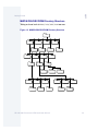
MWOS/OS9/SRC/ROM Directory Structure
Taking a closer look at MWOS/OS9/SRC/ROM we see:
Figure 1-5 MWOS/OS9/SRC/ROM Directory Structure
ROM
CBOOT
COMMON
DEFS
LIB
DEBUGGER
DISK
INETBOOT
DISK
MVME050
SYSBOOT
NETWORK
BOOT5380
BOOT33C93
TAPE
TIMERS
TAPE
BOOTLIB
BOOT327
SERIAL
BOOTMT2ST
BOOTSCCS
BOOT53C094
BOOTVIPER
BOOT374
DESC
OS-9 for 68K Processors OEM Installation Manual
BOOT82596
BOOT7990
BOOTCMC
BOOTBP
29
These directories are as follows:
Table 1-5 MWOS/OS9/SRC/ROM Directories
30
Directory
Contains
CBOOT
Contains almost all of the boot code written in
C (except for some SCSI driver whose
source is shared with the normal running
system drivers). As can be seen in the above
diagram, it has a subdirectory structure
contained within it.
CBOOT/DEFS
Include (.h) files for interface and
media-independent definitions.
CBOOT/DISK
Boot disk driver and descriptor source
subdirectories.
CBOOT/INETBOOT
BOOTP client source.
CBOOT/NETWORK
BOOTP network driver source subdirectories.
CBOOT/SYSBOOT
General purpose booters and common code
libraries.
CBOOT/TAPE
Boot tape driver source subdirectories.
CBOOT/TIMER
BOOTP timer sources.
COMMON
Common assembler sources for all boot
ROMs.
DEBUGGER/ROMBUG
ROMbug debugger source.
DISK
Assembly language boot disk drivers.
OS-9 for 68K Processors OEM Installation Manual
1
Getting Started
Table 1-5 MWOS/OS9/SRC/ROM Directories (continued)
Directory
Contains
LIB
Intermediate object libraries for linkage into
target ROM images.
MVME050
Assembly language system initialization
support routines for the MVME050.
SERIAL
Assembly language low-level console and
communications port drivers.
TAPE
Assembly language boot tape drivers.
OS-9 for 68K Processors OEM Installation Manual
31
Figure 1-6 Object Directories
68000
CMDS
DEFS
LIB
BOOTOBJS
MC6830X
PORTS
SYS
SYSMODS
GCLOCK
MVME050
CMC
MB2470
MVME050
MVME107
MVME320
MVME374
OEM_MINIMUM
68020
CMDS
DEFS
LIB
PORTS
SYS
MVME147
MVME165
MVME167
BOOTOBJS
MVME133
CPU32
CMDS
DEFS
LIB
PORTS
BCC332
BCC340
WW349
SYS
BOOTOBJS
As you can see, there is a different subdirectory structure for each
processor family in the 68000 architecture. Commands and system
modules common across all 68000 families reside in 68000/CMDS and
68000/CMDS/BOOTOBJS. Similarly, descriptors for VMEBus peripherals
(MVME050, MVME320, and MVME374) applying to all 68000 families
reside in the respective directory in 68000/PORTS. Clock drivers specific
to the MVME050 are built in 68000/SYSMODS/GCLOCK/MVME050.
32
OS-9 for 68K Processors OEM Installation Manual
1
Getting Started
Each PORTS directory contains directories for example ports to various
target VMEBus processors (MVME107 in 68000/PORTS; MVME133_4,
MVME147 and MVME165 in 68020/PORTS; BCC332, BCC340, and
WW349 in CPU32/PORTS).
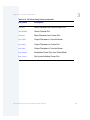
Table 1-6 MWOS Object Directories
Directory
Contains
CBOOT/SYSBOOT
General purpose booters and common code
libraries.
CBOOT/TAPE
Boot tape driver source subdirectories.
CBOOT/TIMER
BOOTP timer sources.
COMMON
Common assembler sources for all boot
ROMs.
DEBUGGER/ROMBUG
ROMbug debugger source.
DISK
Assembly language boot disk drivers.
LIB
Intermediate object libraries for linkage into
target ROM images.
MVME050
Assembly language system initialization
support routines for the MVME050.
SERIAL
Assembly language low-level console and
communications port drivers.
TAPE
Assembly language boot tape drivers.
OS-9 for 68K Processors OEM Installation Manual
33
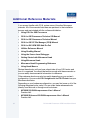
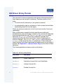
Additional Reference Materials
If you are not familiar with OS-9, review some of the other Microware
manuals. All of the manuals listed here are pertinent to the installation
process and are included with the software distribution.
•
Using OS-9 for 68K Processors
•
OS-9 for 68K Processors Technical I/O Manual
•
OS-9 for 68K Processors Technical Manual
•
OS-9 for 68K PC File Manager (PCM) Manual
•
OS-9 for 68K OEM SSD Add-On Pak
•
Utilities Reference Manual
•
Using RomBug Manual
•
Using the Source Level Debugger
•
Getting Started with Microware Hawk
•
Using Microware Hawk
•
Microware Hawk Programming Reference
•
Using Hawk Macros
Review these books until you have a basic idea of how OS-9 works and
how it is organized. You should be familiar enough with these manuals so
you can easily locate essential information for reference.
Other reference books may also be useful depending on your system’s
configuration. You can order OS-9 Insights and the OS-9 Primer from your
Microware distributor.
Depending on your hardware configuration, you may find some or all of the
following reference books useful. You can order these reference books
directly from Motorola or through most bookstores:
34
•
MC68020 32 Bit Microprocessor User’s Manual
Prentice-Hall
•
MC68030 Enhanced 32 Bit Microprocessor User’s Manual
Prentice-Hall
OS-9 for 68K Processors OEM Installation Manual
1
Getting Started
•
MC68881/MC68882 Floating Point Coprocessor User’s Manual
Prentice-Hall
•
MC68851 User’s Manual
Prentice Hall
•
CPU32 Reference Manual
Motorola
•
MC68332 SIM User’s Manual
Motorola
•
TPU Reference Manual
Motorola
•
Programmer’s Reference Manual
Motorola
You can order this reference book from Signetics or Philips:
16/32 Bit Highly-Integrated Microprocessor SCC68070 User Manual
Philips; Parts I (hardware) and II (software)
OS-9 for 68K Processors OEM Installation Manual
35
36
OS-9 for 68K Processors OEM Installation Manual
C h a p t e r 2 : P o r t i n g O S- 9 f o r 6 8 K
This chapter includes the following topics:
•
Getting Started
•
Understanding the OS-9 for 68K Booting Process
•
The Four Porting Steps
Getting Started
Once you have installed all of OS-9 for 68K’s boot code sources, driver
sources, and system modes (such as the kernel), the sheer volume of files
may overwhelm you.
More In
fo More
Informatio
n More Inf
ormation M
ore Inform
ation More
-6-
For More Information
You should keep in mind Microware provides example source files for
many different types of device drivers, whether they be serial, disk
controller, tickers, or real-time clocks. You only need what your target
hardware has available. If you need the disk space, you can get rid of
the rest. (Remember, your Microware distribution tape, disc, or disks
still contain all of the files.) This can considerably narrow down your
focus of porting.
Knowing your hardware well makes it easier for you to port OS-9 to it. The
following information is extremely helpful during the porting procedure:
38
•
What I/O devices do you have?
•
How are these devices mapped into memory?
•
How is the memory organized?
•
What does the memory map of the entire system look like?
OS-9 for 68K Processors OEM Installation Manual
2
Porting OS-9 for 68K
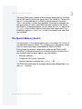
Understanding the OS-9 for 68K Booting
Process
Although the OS-9 system itself (the kernel, file managers, and processes)
is very modular in its architecture, the boot code is different and a
distinction is made between the OS-9 system and the OS-9 boot code. You
can think of the OS-9 boot code as one program, consisting of several
different files, that gets linked together and burned into ROM in order to
bring up the OS-9 system.
A bootfile must exist in order to boot OS-9. This bootfile is simply merged
OS-9 system and program modules, with the kernel usually being the first
module.
Note
The bootfile must contain the kernel.
This bootfile can exist:
•
In ROM
•
On a disk
•
On a tape
•
Any other type of media
The purpose of the boot code is to:
•
Set the hardware into a known, stable state
•
Set up certain table and memory configurations
•
Find the bootfile and start executing the kernel
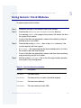
Three steps are necessary to boot OS-9 for 68K. These are covered in the
following pages.
OS-9 for 68K Processors OEM Installation Manual
39
Step 1: Power Up the ROMbug Prompt
Once you supply power to the 68000 processor or a reset occurs, the
processor:
•
Performs a longword read cycle at address 0.
•
Places the result in the a7 register (stack pointer).
•
Performs a longword read cycle at address 4.
•
Places the result into the program counter (PC) register.
•
Starts executing instructions as it normally does.
Note
Step 1 is the most difficult step to complete, and unless you have an
emulator or existing debugger on your running target, much of this step
is done blind. However, once ROMbug is available, it is a good
debugging tool for the remainder of the port.
Many computer boards have address logic that maps these first two reads
to wherever the ROM is actually located. Then, the address mapping
returns to the board’s standard memory map.
Once this has been done, the processor can execute machine language
instructions like it normally does. The initial PC value in the OS-9 boot code
is a label called Reset:. This label is defined in the boot.a file.
More In
fo More
Informatio
n More Inf
ormation M
ore Inform
ation More
-6-
40
For More Information
You can think of boot.a as the kernel for booting. It is prewritten and
you do not have to modify it. Chapter 3: Step One: Porting the Boot
Code, contains additional information about boot.a.
OS-9 for 68K Processors OEM Installation Manual
2
Porting OS-9 for 68K
For more information about sysinit.a, refer to Chapter 3: Step One:
Porting the Boot Code.
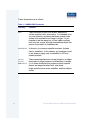
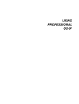
Once boot.a starts executing, it:
Step 1.
Sets up a few variables.
Step 2.
Branches to a label called SysInit.
SysInit is defined in the sysinit.a file. Although examples of
sysinit.a are available from the boot code source, you must modify this
file to initialize specific hardware devices on the target board. SysInit
branches back to boot.a.
boot.a then:
Step 1.
Determines on which processor it is running.
Step 2.
Performs memory searches.
Step 3.
Calls ConsInit in ioxxx.a to initialize the console port.
Step 4.
Calls SysInit2 and UseDebug, which are also defined in the
sysinit.a file.
After returning to boot.a, the ROM debugger is called to give a register
dump of the processor and prompt for more instructions. The following
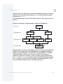
diagram illustrates this process:
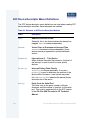
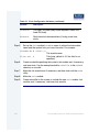
OS-9 for 68K Processors OEM Installation Manual
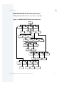
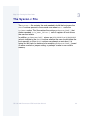
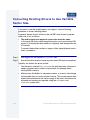
41
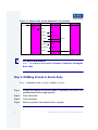
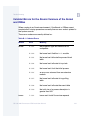
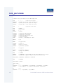
Figure 2-1 Chart of Files and the Subroutines They Contain
Apply power
to processor
vectors
.a
initial SP
initial PC
boot.a
sysinit.a
Reset:
...
bra Sysint
Consinit:
rts
bsr Sysinit2
...
bsr UseDebug
More In
fo More
Informatio
n More Inf
ormation M
ore Inform
ation More
-6-
ROMbug
Sysinit:
...
Bra SysRetrn
SysRetrn:
...
bsr Consinit
...
...
...
bsr Debug
ioxxx.a
Sysinit2:
rts
UseDebug:
rts
At Rombug's
prompt
For More Information
Boot.a is covered in more detail in Chapter 3: Step One: Porting the
Boot Code.
Step 2: ROMbug Prompt to Kernel Entry
boot.a branches to the SysBoot routine. SysBoot:
Step 1.
Prompts the operator for the boot media or (optionally) auto-boots from
predetermined media (target specific)
Step 2.
Finds the bootfile
Step 3.
Finds the kernel
Step 4.
Returns a pointer to the kernel in the a0 register
42
OS-9 for 68K Processors OEM Installation Manual
2
Porting OS-9 for 68K
Once SysBoot has found the bootfile and the kernel’s pointer is returned to
boot.a, boot.a:
Step 1.
Sets up the registers according to the kernel’s specifications
Step 2.
Jumps to the execution entry point in the kernel
Step 3: Kernel Entry Point to $ Prompt
The cold part of the kernel finishes the task of booting OS-9. It sets up
variables in the system global data table (commonly referred to as the
system globals). It also:
•
Builds the kernel’s RAM memory pools by searching the memory list
•
Builds the module directory by searching colored memory ROM areas,
special memory areas, and ROM memory areas
•
Initializes system tables (such as the device path table)
From here, it does the following:
Step 1.
Open the console device
Step 2.
Chd to the system device
Step 3.
Execute any P2 modules from the Init module’s Extens list
Step 4.
Fork the first process
The cold part of the kernel then disinherits the first process and exits by
calling the kernel’s system execution loop. The OS-9 system should now be
booted and executing as expected.
OS-9 for 68K Processors OEM Installation Manual
43
More In
fo More
Informatio
n More Inf
ormation M
ore Inform
ation More
-6-
44
For More Information
For more information about the kernel’s cold routine, refer to Chapter 4:
Step Two: Bringing Up the Kernel and Console I/O.
OS-9 for 68K Processors OEM Installation Manual
2
Porting OS-9 for 68K
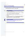
The Four Porting Steps
Four steps are required to port OS-9 on your target hardware. The following
chapters explain these procedures in greater detail.
Step 1.
More In
fo More
Informatio
n More Inf
ormation M
ore Inform
ation More
-6-
Porting the boot code.
This procedure includes steps 1 and 2 of the OS-9 boot process. The
files needed to accomplish this are vectors.a, boot.a, ioxxx.a,
ioyyy.a, sysinit.a, systype.d, syscon.c, bootio.c, and the
sysboot and rombug libraries. This step includes:
•
Hardware dependent initialization and configuration (sysinit.a).
•
ROMbug.
•
The ability to boot from ROM or an image downloaded into RAM. You
must define key labels in systype.d and the makefile to correctly
configure the code for your particular target hardware.
For More Information
Chapter 3: Step One: Porting the Boot Code, contains more
information about the files needed.
OS-9 for 68K Processors OEM Installation Manual
45
Note
For your initial port of OS-9 to your target, we strongly recommend you
first create a ROM/RAM based system to reduce the complexity of the
port (downloading target-specific modules into RAM through ROMbug’s
communication port from the development system). Later, as more of
the port is accomplished, you can incorporate other booting methods.
For this reason, source for a simple ROM/RAM boot routine has been
included in Appendix F: Example ROM Source and Makefiles. This
simple menu booter is syscon.c.
Step 2.
More In
fo More
Informatio
n More Inf
ormation M
ore Inform
ation More
-6-
Porting the OS-9 kernel and basic I/O system.
This involves more modification to the systype.d file. You need to
make an Init module and high-level serial drivers and descriptors for
your particular hardware. Once this is complete and is working, a
ROM-able OS-9 system exists.
For More Information
The Init module is a data module from which the kernel configures
itself. For more information about the Init module, refer to Chapter 2,
The Kernel, in the OS-9 for 68K Technical Manual.
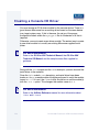
Step 3.
Creating customized I/O drivers and finishing the boot code.
In this porting procedure, more high-level drivers are developed and
debugged for other serial ports, disk drivers and controllers, clocks, and
any other available devices. Once the high-level drivers are working,
you can modify the boot code to boot from the various devices
available. The C boot routines are good in this regard.
For example, once the basic port of a board has been completed (porting
procedure’s 1 and 2), a high-level driver for a floppy drive (or other
installable media) is developed next. Once it is known to work, you can
46
OS-9 for 68K Processors OEM Installation Manual
2
Porting OS-9 for 68K
format a floppy disk and install an OS-9 bootfile on the floppy. At this point,
you can create a low-level driver for C boot (which may use much of the
same logic and code as the high-level driver) that boots the system from
the floppy.
Step 4.
Testing and Validation
This involves the final testing and verification of the complete system.
Your distribution package was designed to follow this procedure.
OS-9 for 68K Processors OEM Installation Manual
47
48
OS-9 for 68K Processors OEM Installation Manual
C h a p t e r 3 : St e p O n e : P o r t i n g t he B o o t
Code
This chapter includes the following topics:
•
Introduction
•
The Defsfile File
•
The Oskdefs.d File
•
The Systype.d File
•
The Vectors.a File
•
The Boot.a File
•
The ioxxx and ioyyy Files
•
I/O Driver Entry Points
•
The Sysinit.a File
•
The Syscon.c File
•
The initext.a File
•
Putting the ROM Together
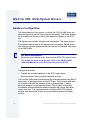
Introduction
This chapter deals with the first step of porting OS-9 for 68K. This involves
creating and installing a ROM that contains the system initialization code
and a special ROM debugger (ROMbug).
About the Boot Code
In a sense, the name boot code can be misleading. The boot code does not
try to boot the system by reading data from a disk; this comes in a later
step. At this point, the boot code has the following functions:
•
initialize the basic CPU hardware into a known, stable state
•
determine the extent and location of RAM and ROM memory
•
provide low-level console I/O
•
call the ROMbug debugger
The ROMbug debugger is located in the same part of the ROM as the boot
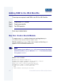
code. The ROMbug debugger can download software from the host
system. It provides powerful debugging facilities such as:
•
Tracing
•
Single instruction stepping
•
Setting breakpoints
The ROMbug debugger remains in place for the entire porting process. It
can also be used to help debug all of your applications, especially any
system state or driver code. However, for your final production ROM, you
may wish to exclude ROMbug.
The ROM is made from a number of different files linked together to
produce the final binary object code. The vast majority of the code is not
system dependent and therefore is supplied in relocatable object code form
(files with.r or.l suffixes). You only have to edit a few source files. You
then use the make command to assemble these files and link them with the
other.l files to create the ROM binary image file.
50
OS-9 for 68K Processors OEM Installation Manual
3
Step One: Porting the Boot Code
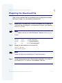
How to Begin the Port: The Boot Code
The first step in porting OS-9 is to port the boot code, or basically the code
always residing in the ROM. To do this, you need to create several files in a
new PORTS/<target> directory:
Table 3-1 Ports Directory Files
Name
The File Should Contain
systype.d
The target system, hardware-dependent definitions.
sysinit.a
Any special hardware initialization your system may
require after a reset occurs.
Note
These files are specific to your particular hardware. systype.d and
sysinit.a are covered later in this chapter.
The files provided in Appendix F: Example ROM Source and Makefiles
are code to a working example and will not work for your particular
hardware. However, these are minimal examples and can be reworked to
match your hardware if necessary. Create these files in your own
PORTS/<target> directory in one of the processor family object
directories.
In most cases, you do not need to write the low level drivers, ioxxx.a and
ioyyy.a, because the Development Kit contains code to many existing
devices. If you have a device for which code has not been written, the entry
points needed for drivers are documented later in this chapter.
OS-9 for 68K Processors OEM Installation Manual
51
Note
Do not modify the other files, such as vectors.a, boot.a, and
sysboot.a. Altering these files may cause the port to not function.
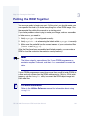
Once you have properly adjusted the systype.d and sysinit.a files,
use the make-f=rombug.make command to produce a ROM image file.
Testing the Boot Code
To test the boot code:
Step 1.
Burn a set of ROMs with this image.
Step 2.
Turn on your hardware.
Step 3.
See if a ROM debugger prompt comes up.
•
If the ROM debugger prompt does come up, you have successfully
completed the initial port and are ready to continue.
•
If it does not come up, look at Appendix B: Trouble Shooting.
ROM Image Versions
Generally, two slightly different makefiles exist in the PORTS/<target>
directory: rombug.make and rom.make.
1. rombug.make: Full boot menu with ROMbug.
Contains all the C boot functionality with the ROMbug ROM debugger.
This is a large image found in PORTS/<target>/
CMDS/BOOTOBJS/ROMBUG/rombug.
52
OS-9 for 68K Processors OEM Installation Manual
3
Step One: Porting the Boot Code
2. rom.make: Full boot menu.
Contains the C boot functionality without a ROM debugger. This image
is much smaller than the ROMbug image alone. Find it in the
PORTS/<target>/CMDS/BOOTOBJS/NOBUG/rom. This could be
considered the final production version.
Component Files of the ROM Image
The rombug.make and rom.make makefiles create the ROM image by
combining and linking several sets of files to make the binary object code:
•
The common target startup (rom_common.l).
This is built from target-independent source files (vectors.a and
boot.a) in the SRC/ROM/COMMON directory.
Table 3-2 Common Target Startup Source Files
Source
Relocatable
Contents
System-wide hardware definitions
systype.d
boot.a
boot.r
Standard system initialization code
vectors.a
vectors.r
Exception vector table
•
The low-level serial IO code (rom.serial.l)
This is built from target-independent source files (ioxxx.a, and
ioyyy.a, if needed) in the SRC/ROM/SERIAL directory.
OS-9 for 68K Processors OEM Installation Manual
53
Table 3-3 Low-level IO Serial Source Files
Source
Relocatable
Contents
ioxxx.a
ioxxx.r
Console device primitive I/O routines*
ioyyy.a
ioyyy.r
Communication port I/O routines*
* The actual names of the files ioxxx.a and ioyyy.r vary according to the hardware
device type. For example, a driver for a Motorola 6850 has the name io6850.a,
and so on.
•
The target-specific startup and bootmenu code (rom_port.l)
This is built from target-specific source files (sysinit.a, syscon.c,
and bootio.c) in the PORTS/<target> directory.
Table 3-4 Target-specific Startup and Bootmenu Code Source Files
Source
Relocatable
Contents
sysinit.a
sysinit.r
Custom initialization code
syscon.c
syscon.r
Custom initialization code
bootio.c
bootio.r
I/O support routines for binboot()
•
54
The CBoot libraries (sysboot.l and romio.l)
OS-9 for 68K Processors OEM Installation Manual
3
Step One: Porting the Boot Code
Table 3-5 C Boot Libraries
Source
•
Relocatable
Contents
sysboot.l
sysboot library routines.
romio.l
I/O routines for CBoot and ROM
debugger.
The debug files (rombug.l).
This code is used during the port; you can exclude it from the final
production boot ROM. All debug files are provided in relocatable format.
The source code to the debug files is not supplied with the Developers
Kit because you do not need to edit or assemble these files.
Table 3-6 Debug Libraries
Source
Relocatable
Contents
rombug.l
Full featured ROM debugger
Note
Not all of the relocatable files listed are supplied in the distribution
package; some are created during the porting process.
OS-9 for 68K Processors OEM Installation Manual
55
!
WARNING
Read the rest of this chapter before you begin editing the systype.d
file!
56
OS-9 for 68K Processors OEM Installation Manual
3
Step One: Porting the Boot Code
The Defsfile File
The defsfile file acts as a master include file to include all definition
(.d) files within assemblies in the PORTS/<target> directory. defsfile
typically includes <oskdefs.d> (from SRC/DEFS) and systype.d (from
PORTS/<target>) at a minimum.
OS-9 for 68K Processors OEM Installation Manual
57
The Oskdefs.d File
The oskdefs.d file is OS-9’s system-wide symbolic definitions file. It can
be found in the SRC/DEFS directory. oskdefs.d defines some of the
names used in systype.d.
Note
Do not edit oskdefs.d. oskdefs.d is used for generic system-wide
target-independent definitions only. If system specific definitions are
needed, edit systype.d.
You should make a listing of both systype.d and oskdefs.d. Study
them so you understand how they are used and how they are related. If you
have undefined name errors when assembling various other routines later,
the files were probably not included or were not configured properly.
Notice that many hardware-dependent values and data structures are
defined as macros in systype.d. These macros are used in many other
parts of the boot ROM as well as files used in later stages of the
installation. In particular, device driver and descriptor source files reference
these macros.
58
OS-9 for 68K Processors OEM Installation Manual
3
Step One: Porting the Boot Code
The Systype.d File
The systype.d file should contain the target system,
hardware-dependent definitions. This includes:
•
Basic memory map information
•
Exception vector methods (for example, vectors in RAM or ROM)
•
I/O device controller memory addresses
•
Initialization data
Note
Target-specific definitions are all included in the systype.d file. This
allows you to maintain all target system specific definitions in one file.
You must create a systype.d file before you re-assemble any other
routines.
systype.d is included in the assembly of many other source files by
means of the assembler’s use directive. You need to make a new
systype.d file defining your target system as closely as possible, using
the sample file provided in the distribution package. Some definitions are
not used until later in the porting process, so some of these definitions are
not covered until later in this manual.
systype.d consists of five main sections used when porting OS-9:
1. ROM configuration values.
2. Target system specific definitions.
3. Init module CONFIG macro.
4. SCF device descriptor macros and definitions.
5. RBF device descriptor macros and definitions.
OS-9 for 68K Processors OEM Installation Manual
59
The ROM configuration values and the target system specific definitions
are the only sections important for the boot code. Therefore, these section
are covered in this chapter. Chapter 4: Step Two: Bringing Up the Kernel
and Console I/O covers the remaining sections.
The ROM Configuration Values
The ROM configuration values are normally listed at the end of the
systype.d file. These values are used to construct the boot ROM and
consist of the following:
•
Target specific labels
•
Target configuration values
•
Low level device values
•
Target system memory definitions
Target Specific Labels
Target specific labels are label definitions specific for your target hardware.
They can define:
•
Memory locations for special registers on your hardware.
•
Specific bit values for these registers.
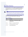
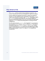
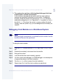
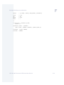
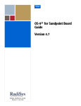
For example, your target hardware processor has a register controlling to
which interrupt levels on a bus the board responds. This may be necessary
if several target boards are sharing the same bus, and you would like to
have different boards handle different interrupt levels. The base of all your
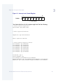
control registers on your board starts at address F800 0000 and the offset
to this particular register is 8. The register is a single byte, with each bit
corresponding to an interrupt level. Setting the bit enables the interrupt.
Conceptually, the register may look something like the following:
60
OS-9 for 68K Processors OEM Installation Manual
3
Step One: Porting the Boot Code
Figure 3-1 Interrupt Level Control Register
7
F8000008
NA
0
L7
L6
L5
L4
L3
L2
L1
L = IRQ Level
Your label definitions for this register might look like the following:
* Define control registers.
ControlBase equ $f800 0000
.
.
* Other registers defined.
.
.
IRQControl equ ControlBase+8
.
.
Other registers defined.
.
.
* Define Control Register Values
Level1Enable equ %00000001
Level2Enable equ %00000010
Level3Enable equ %00000100
Level4Enable equ %00001000
Level5Enable equ %00010000
Level6Enable equ %00100000
Level7Enable equ %01000000
.
.
DisableAll equ 0
LowlevelEnable equ
Level1Enable+Level2Enable+Level3Enable
HighLevelEnable equ Level4Enable+Level5Enable+Level6Enable
EnableAll equ LowLevelEnable+HighLevelEnable+Level7Enable
OS-9 for 68K Processors OEM Installation Manual
61
Note
This is only an example and more than likely is not valid for your
hardware. However, it does show you how to handle these definitions.
If your hardware:
•
has a lot of special registers such as these, this can be a lengthy list.
•
does not have many registers like this, the list can be very short.
You can review the supplied systype.d files to see how to define
hardware registers. However, the values in the supplied systype.d file
will not work on your target hardware.
For more information about the use of these labels, refer to the section on
the sysinit.a file.
62
OS-9 for 68K Processors OEM Installation Manual
3
Step One: Porting the Boot Code
Target Configuration Labels
The target configuration labels are needed to configure the boot code
properly for your target hardware. The following are a list of these variables:
Table 3-7 Target Configuration Labels
Label
Effect
ROMBUG
Specify ROMbug is used. The initial stack area is
increased in size to accommodate the larger usage
by the C drivers, and the size of the ROM global
data area is determined dynamically. Several of the
vectors are pointed into the ROMbug handlers.
Boot.a also calls the ROMbug initialize data routine.
CBOOT
Specify CBOOT technology is to be used. The ROM
global data area size is determined dynamically.
You can also use this flag to enable sync-codes in
assembler code. This allows the assembler boot
drivers to be interfaced with the CBOOT sysboot
routines.
RAMVects
Specify the vectors are in RAM. This allows boot.a
to copy the vectors to the appropriate place.
PARITY
Specify parity memory is present. boot.a initializes
parity by writing a pattern into the memory. The
MemList macro in systype.d defines the memory
to initialize.
OS-9 for 68K Processors OEM Installation Manual
63
Table 3-7 Target Configuration Labels (continued)
Label
Effect
MANUAL_RAM
Specify you must explicitly enable RAM memory.
This enabling is usually performed in SysInit.
Therefore, the 32-bit bra to SysInit does not work
if you have not enabled the RAM. To allow operation
in this situation, define MANUAL_RAM, and the call to
SysInit is a straight bra instruction. This means
the bra target must be within a 16-bit offset.
TRANSLATE
Define the value to use for the boot driver DMA
address translation. If the local CPU memory
appears at a different address for other bus
masters, boot drivers can access the global
TransFact label to determine the system’s
address translation factor. If this label is not defined,
TransFact defaults to 0.
VBRBase
Define the address for the system’s Vector Base
Register (68020, 68030 68040, and CPU32
processors only). Boot code can access the global
VBRPatch label defined in boot.a to determine
where the vectors are located. If this label is not
defined, VBRPatch defaults to 0.
CPUTyp
Specify the CPU type. Valid values for CPUTyp are
defined in the next section.
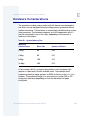
CPUTyp Label and Supported Processors
The large number of variations of processors available from Motorola
makes it important to ensure the label CPUTyp (defined in systype.d for
your system) is correctly set, so certain features of the BootStrap code are
correctly invoked.
64
OS-9 for 68K Processors OEM Installation Manual
3
Step One: Porting the Boot Code
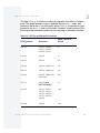
The label CPUTyp is used for conditional assembly of portions of the boot
code. The actual processor type is detected by the boot.a code, and
passed to the kernel. If you incorrectly define CPUTyp, the processor type
passed by the boot.a code is still correct; however, some portions of the
bootstrap code may have conditional parts missing or incorrectly invoked.
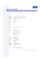
Table 3-8 CPUTyp and Related Processors
Value Passed to
Kernel
CPUTyp Value
Processor
68000
68000, 68008,
68301, 68303,
68305, 68306
0
68302
68302
0
68010
68010
10
68020
68020, 68EC020
20
68030
68030, 68EC030
30
68040
68040, 68EC040,
68LC040
40
68070
68070 (aka
9xC1x0-family)
70
68300
68330, 68331,
68332, 68333,
68334, 68340,
68341, 68349,
68360
300
68349
68349
300
OS-9 for 68K Processors OEM Installation Manual
65
Note
The naming conventions for 683XX processors can be confusing. The
processors numbered in the range 68301 - 68306 are 68000 core
based processors, and thus (from a software point of view) the boot.a
code takes any value of CPUTyp in the range from 68301 to 68309 to
be a 68000 processor. The processors in the number range 68330 and
up are CPU32 or CPU32+ (aka CPU030) based cores, and thus the
boot.a code takes any value of CPUTyp in the range from 68330
through to 68399 as a CPU32-based processor.
CPUTyp having a value of 68302 causes the boot.a code to reserve
vectors 60 - 63, but otherwise it is treated like a 68000.
The value passed to the kernel is a biased value, as the kernel adds a
value of 68000 to the value passed up, and then stores this new value
in the kernel's system global D_MPUTyp.
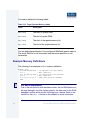
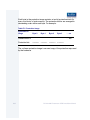
Low Level Device Configuration Labels
Low level device configuration labels configure the low level I/O. These
values are as follows:
Table 3-9 Low-level Device configuration Levels
66
Label
Effect
Cons_Addr
This is the base address of the console device. This is
used by the low level ioxxx.a serial driver.
ConsType
This is used by the ioxxx.a code to determine which
device is the console.
OS-9 for 68K Processors OEM Installation Manual
3
Step One: Porting the Boot Code
Table 3-9 Low-level Device configuration Levels (continued)
Label
Effect
Comm_Adr
This is the base address of the communications port,
or Comm port. It is used by the ROM debugger to
download S-record files from the host.
CommType
This is used by the ioyyy.a code to determine which
device is the Comm port.
Each individual ioxxx.a and ioyyy.a driver has its own configuration
labels. These labels are defined for each driver within the source of the
driver, as well as Appendix C of this manual. Refer to the driver you will
use, and set these labels correctly.
You need to define the following labels for the low level disk booter:
•
FD_Vct
• FDsk_Vct
• SysDisk
You should define these labels as 0 if you do not have a disk booter.
Target System Memory Labels
Target system memory labels define where system memory is located. The
MemDefs macro in the systype.d file is the mechanism in the boot code
to define memory. It consists of two areas:
•
General system free RAM
•
Special memory
The free RAM is self-explanatory. The special memory definitions are the
areas through which the kernel searches for modules when booting.
OS-9 for 68K Processors OEM Installation Manual
67
You need to define the following labels:
Table 3-10 Target System Memory Labels
Label
Description
Mem.Beg
The start of system RAM.
Mem.End
The end of system RAM.
Spc.Beg
The start of the special memory list.
Spc.End
The end of the special memory list.
You can define several banks of non-contiguous RAM and special memory.
The entire RAM list is null terminated, and the entire special list is null
terminated.
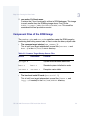
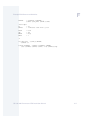
Example Memory Definitions
The following is an example MemDef memory definition:
MemDefs macro
dc.l Mem.Beg,Mem.End
dc.l 0
dc.l Spc.Beg,Spc.End
dc.l 0
dc.l 0,0,0,0,0,0,0,0
endm
More In
fo More
Informatio
n More Inf
ormation M
ore Inform
ation More
-6-
68
*
*
*
*
*
1st RAM bank start/end address
Null terminator
1st special bank start/end addr
Null terminator
Additional places for padding
For More Information
Due to the way the boot code has been written, the first RAM bank must
be large enough to hold the system globals, the data area for the ROM
debugger, and the entire bootfile if booting from a device. Refer to the
section on the boot.a file later in this chapter for more information.
OS-9 for 68K Processors OEM Installation Manual
3
Step One: Porting the Boot Code
Note
Since the list is a null terminated list, never define Mem.Beg or
Spc.Beg as 0. Mem.Beg is usually offset by 0x400 bytes to allow room
for the vector table. This is especially important if VBRBase is set to an
area of RAM.The memory location of the vectors and general system
RAM memory must not exist in the same place. If you have a ROM
bank starting at 0, be sure to offset the Spc.Beg by an even number of
bytes, usually 2 to 4.
The following is another MemDef example. This example has multiple
banks of RAM and special areas:
MemDefs macro
dc.l Mem.Beg,Mem.End
dc.l Mem1.Beg,Mem1.End
dc.l Mem2.Beg,Mem2.End
dc.l 0
dc.l Spc.Beg,Spc.End
dc.l Spc1.Beg,Spc1.End
dc.l 0
dc.l 0,0,0,0,0,0,0,0,
endm
1st RAM bank start/end address
2nd RAM bank start/end address
3rd RAM bank start/end address
Null terminator
1st special bank start/end addr
2nd special bank start/end addr
Null terminator
Additional padding for patching
The additional areas for patching allow you to patch the memory list without
remaking the ROM image.
Note
As described later in boot.a, the RAM search is a destructive search,
and the special memory search is a non-destructive, read-only search.
OS-9 for 68K Processors OEM Installation Manual
69
!
WARNING
During the initial porting phase, it is often customary to define an area
of RAM as special memory, in addition to any ROM areas. The reason
for this is when you try to debug any high level drivers, either the serial
driver or later, the disk driver, it is easier to download the driver to RAM,
debug it there, make changes in the source, and when rebooting,
download the driver again. This way, you do not need to burn an
EPROM every time you change the driver. This special area of RAM
must be carved out of the normal RAM list and put as a separate bank
of special memory. Once the port is complete and all drivers are
debugged, the special RAM area can be returned to the general RAM
memory list. Modules needed in the bootlist are covered further in
Chapter 4: Step Two: Bringing Up the Kernel and Console I/O.
70
OS-9 for 68K Processors OEM Installation Manual
3
Step One: Porting the Boot Code
The Vectors.a File
The vectors.a file contains definitions for the exception vector table. You
normally do not need to edit this file unless your target system has an
unusual requirement.
More In
fo More
Informatio
n More Inf
ormation M
ore Inform
ation More
-6-
For More Information
Refer to Appendix D: SCSI-System Notes for details of the conditional
assembly flags used by this file.
Depending on your system hardware, the actual vectors can be located in
RAM or ROM. To specify the location of the vectors, define the label
RAMVects in the systype.d file. If ROM space is exceedingly tight, all
vectors (except the reset vectors) may be located in RAM. This is only
possible if the final production version of the boot ROM has no ROM
debugger and the reset vectors are included in ROM. This saves a little
ROM space due to lack of duplication.
OS-9 for 68K Processors OEM Installation Manual
71
The Boot.a File
The boot.a file contains the system initialization code that is executed
immediately after a system reset. You should not need to edit this file. The
sysinit.a file is reserved as a place for you to put code for any special
hardware initialization your system might require after reset.
Steps Boot.a Goes Through to Boot the Kernel
Boot.a goes through the following steps to boot the kernel:
Step 1.
Assume a full cold start for growth method.
The kernel validates modules using a growth method.
•
With a full growth method, when the kernel validates modules, it first
validates the module header and then validates the full module’s CRC
number.
•
With a quick growth method, the kernel simply validates the module
header. Although booting is quicker, there is more room for error. A
module may be in memory and may be corrupted.
Step 2.
Mask interrupts to level 7.
Interrupts are masked to ensure the boot code has a chance to run.
Step 3.
Call the SysInit label.
SysInit ensures all interrupts are cleared and the hardware is in a
known, stable state.
More In
fo More
Informatio
n More Inf
ormation M
ore Inform
ation More
-6-
72
For More Information
SysInit is defined in the sysinit.a file.
OS-9 for 68K Processors OEM Installation Manual
3
Step One: Porting the Boot Code
Step 4.
Clear out RAM.
Clears out the RAM used for the system globals and the global static
storage used by ROMbug and the boot code.
Step 5.
Record growth method in the Crystal global variable.
This growth method is passed to the kernel when the kernel is jumped
to.
Step 6.
Set up 68000 vector table to vbr register or memory location 0 if
needed.
If the vector needs to be copied from the ROM to a RAM area, this is
where it occurs. This copy occurs if the RAMVects label is defined.
Step 7.
Set up OS-9 exception jump table.
The exception jump table is an intermediate table between the vector
table and the kernel. The pea and jmp instructions are set up in the
table at this time.
Each vector in the vector table points to a particular entry in the exception
jump table. Each entry in the exception jump table has the following format:
pea #vector_table_address,-(a7)
jmp #vector_exception_handler
Step 8.
Initialize global data for RomBug, if needed.
If you use RomBug, its global data needs to be initialized before it can
run.
Step 9.
Determine CPU type.
Possible CPU types include 68000, 68010, 68020, 68030, 68040,
68070, or 68300. The CPU type is saved in the MPUType system global
variable. When running, the kernel keys off of this variable to determine
the type of processor on which it is running.
Step 10. Branch to the UseDebug label.
If UseDebug returns with the zero bit in the CCR cleared, the ROMbug
is enabled.
OS-9 for 68K Processors OEM Installation Manual
73
More In
fo More
Informatio
n More Inf
ormation M
ore Inform
ation More
-6-
For More Information
UseDebug is located in the sysinit.a file.
Step 11. Initialize ROMbug if it is enabled.
Step 12. Run the SysInit2 routine.
Perform any final hardware initialization.
More In
fo More
Informatio
n More Inf
ormation M
ore Inform
ation More
-6-
For More Information
SysInit2 is also located in the sysinit.a file.
Step 13. Initialize the Console port and print boot strap message.
This is the first sign the system is doing anything.
Step 14. Perform RAM and special memory searches of memory and parity
enable memory if needed.
The routines use both bus error and pattern matching to determine
RAM and ROM sizes. This relies on the MemDefs macro to determine
the memory areas to search.
Step 15. Enter ROMbug if it is enabled.
The debugger is finally reached. At this point, everything needed to find
the kernel has been done.
Step 16. Call SysBoot label to obtain kernel.
You determine how this code works. A pointer to the kernel is all that
needs to be returned.
74
OS-9 for 68K Processors OEM Installation Manual
3
Step One: Porting the Boot Code
Note
There are several routines written to help. sysboot.a is a routine that
searches the ROM area for the kernel. There is no need to adjust this
file, it works as is.
The C boot routines are also available to simplify booting from various
devices.
SysBoot has the following register conventions when it is jumped to:
Table 3-11 SysBoot Register Conventions
Register
Description
a1
Boot ROM entry point.
a3
Port address from DiskPort label.
a4
System free RAM list.
a5
Exception jump table pointer.
a6
Operating system global data area
(4K scratch memory).
a7
System ROM list.
OS-9 for 68K Processors OEM Installation Manual
75
When SysBoot returns, the following registers must be set as follows:
Table 3-12 Registers Set After SysBoot Returns
Register
Description
a0
Pointer to an executable module with a valid header
(hopefully, the kernel).
a4
Possibly updated free RAM list.
a5
Must be intact from above.
a7
Possibly updated system ROM list.
cc
Carry set, d1.w error status if bootstrap failed.
Step 17. Validate the kernel.
After SysBoot returns to boot.a with a pointer to the kernel, boot.a
validates the kernel header.
Step 18. Initialize registers for entry to the kernel.
Before entering the kernel, the registers should have the following
conventions:
Table 3-13 Registers Prior to Entering Kernel
76
Register
Description
d0.l
Total RAM found in the system.
d1.l
MPUType.
d2.l
Trapflag for system debug.
d3.l
Growth startup method.
OS-9 for 68K Processors OEM Installation Manual
3
Step One: Porting the Boot Code
Table 3-13 Registers Prior to Entering Kernel (continued)
Register
Description
d4-d7
Clear.
a0
Kernel entry point.
a1
Boot ROM entry point.
a2-a3
Clear.
a4
System free RAM list.
a5
Exception jump table pointer.
a6
Operating system global data area
(4K scratch memory).
a7
System ROM map.
Step 19. Jump to the kernel’s execution point.
Memory Search Explanations
An important function of boot.a is building the system’s memory
allocation using a memory search list. OS-9 uses this search list to define
the usable areas of the target system’s RAM and special memory. You do
not have to edit boot.a to change this table; the table is defined by the
MemDefs macro in the systype.d file.
OS-9 for 68K Processors OEM Installation Manual
77
The RAM Search
The first part of the search list defines the areas of the address space
where OS-9 should normally search for RAM memory. This reduces the
time it takes for the system to perform the search. It also prevents the
search (and also OS-9) from accessing special use or reserved memory
areas such as I/O controller addresses or graphics display RAM.
The first entry, or bank, in this list must point to a block of RAM that is at
least long enough for storing system global data and global data for
ROMbug and boot code. This is the area of memory cleared out by Step 4
of the boot.a process. If the system boots from disk or another device,
then this first bank needs to be large enough to hold:
•
The system globals
•
The global data needed by the ROMbug and boot code
•
The size of the bootfile
Note
Two factors determine the size of the system’s ROM global data space:
• The required stack size.
• The amount of vsect and initialized data space used by the code.
Memory allocated for initialized and vsect data is part of the bootrom
global data area, and thus permanently allocated for bootrom
functions. If a boot driver requires large buffers (for example, disk sector
blocks), they can be dynamically allocated from and returned to the free
memory pool. The CBOOT system provides routines to do this. The
linker executed in rom_image.make reports the actual required global
data space.
78
OS-9 for 68K Processors OEM Installation Manual
3
Step One: Porting the Boot Code
The actual RAM memory search is performed by reading the first four bytes
of every 8K memory block of the areas given in the search list. If a bus error
occurs, it is assumed there is no RAM or special memory in the block.
Then, a test pattern is written and read back. If the memory changed, the
search assumes this was a valid RAM block and is added to the system
free RAM list. As described earlier, you can define the PARITY label in the
systype.d file to initialize memory before any read is performed. This
initialization pattern is $FEEDCODE, in order to more easily see what RAM
was initialized.
The Special Memory Search
The second part, or the special memory part, of the search list is strictly a
non-destructive memory search. This is necessary so the memory search
does not overwrite modules downloaded into RAM or NVRAM.
During the porting process, temporarily include enough RAM (usually
about 64K) in the special memory list to download parts of the boot file. If
this download area has parity memory, you may need to:
•
Manually initialize it
•
Disable the CPU’s parity, if possible
•
Include a temporary routine in the sysinit.a file
The RAM and special memory searches are performed during Step 14 of
the boot.a process.
OS-9 for 68K Processors OEM Installation Manual
79
The Patch Locations
Two globally available patch locations are available for the following
functions:
Table 3-14 Functions with Patch Locations
Name
Description
TransFact
This is a 32-bit location representing the translation
constant between the CPU’s address versus a DMA
device’s address for the same location. The default
value is 0. Boot drivers using DMA should use this
value when passing address pointers to/from the
DMA device.
VBRPatch
This is a 32-bit location you can use to set the VBR of
the 68020, 68030, 68040, and CPU32 processors if
the vectors are to be located at an address other than
the default value of 0.
NOTE: Relocating the VBR is not supported for the
68000, 68008, 68010, and 68070 processors.
More In
fo More
Informatio
n More Inf
ormation M
ore Inform
ation More
-6-
80
For More Information
Refer to Chapter 7: Miscellaneous Application Concerns, for details
of the conditional flags overriding the default values.
OS-9 for 68K Processors OEM Installation Manual
3
Step One: Porting the Boot Code
The ioxxx and ioyyy Files
Two source files contain very low-level I/O subroutines to handle the
console I/O port and the communications port.
•
The console I/O routines are used by the boot for error messages and
by the debugger for its interactive I/O.
•
The communications port is used for the download and talk-through
functions.
Note
In this manual, the console I/O routine files are referred to as io.xxx
and io.yyy. The actual names of these files usually reflect the names
of the hardware interface devices used by the specific target system.
For example, a source file for the Motorola 6850 device is called
io6850.a, a source file for the Signetics 2661 is called io2661.a,
and so on.
If your target system uses a common type of I/O device, you can probably
use a Microware-supplied file directly or with little modification. Otherwise,
you need to create a new source file using the supplied files as examples.
Note
The physical I/O port addresses and related information are obtained
from systype.d. If the console port and the communications port use
the same type of device, you can use a single, combined file for both.
OS-9 for 68K Processors OEM Installation Manual
81
I/O Driver Entry Points
The low level I/O drivers are generally polled drivers allowing themselves to
force themselves onto the port if necessary. The driver consists of two
sides:
•
A console side (for connection to an operator’s terminal).
•
A communications side (for connection to a host system that facilitates
downloading object files into the target).
These are commonly referred to as the Console port and the Comm port,
respectively.
Many of Microware’s example low-level serial drivers conditionally
assemble entry points and support routines for the console side separately
from the communications side. The ConsType and CommType symbol
definitions (in systype.d) control this conditional assembly. Also,
whenever possible, the drivers are written to be port independent (for
multi-port devices). The ConsPort and CommPort symbol definitions (in
systype.d) then direct the driver to a specific port. These techniques
greatly facilitate multi-driver coexistence and code reuse from one target to
another. See Appendix C: Low-level Driver Flags for the values of these
definitions.
The following describes the entry points into the driver:
Table 3-15 I/O Driver Entry Points
82
Entry Point
Description
ChekPort
Check Comm Port
ConsDeIn
Deinitialize Console Port from Polled Mode
ConsInit
Initialize Console Port
ConsSet
Disable Console Port
OS-9 for 68K Processors OEM Installation Manual
3
Step One: Porting the Boot Code
Table 3-15 I/O Driver Entry Points (continued)
Entry Point
Description
InChar
Read Character from Device’s Input Port
InChChek
Check Console Port
InPort
Read Character from Comm Port
OutChar
Output Character to Console Device
OutPort
Output Character on Comm Port
OutRaw
Output Character to Console Device
PortDeIn
Deinitialize Comm Port from Polled Mode
PortInit
Set Up and Initialize Comm Port
OS-9 for 68K Processors OEM Installation Manual
83
ChekPort
Check Comm Port
Synopsis
ChekPort
Input
None
Output
d0.l character read or -1 if no data available
Description
ChekPort checks the Comm input port to determine if a character is
available to be read, and if so, return the character. If no character is
available, ChekPort must return -1.
This is similar to the InChChek routine for the Console port.
84
OS-9 for 68K Processors OEM Installation Manual
3
Step One: Porting the Boot Code
ConsDeIn
Deinitialize Console Port from Polled Mode
Synopsis
ConsDeIn
Input
None
Output
None
Description
ConsDeIn deinitializes the Console port from the polled mode to the
interrupt driven I/O the high level drivers use. The ROM debugger calls
ConsDeIn before resuming normal time sharing. Essentially, ConsDeIn
should restore the state of the I/O device, which the ConsInit function
saved.
OS-9 for 68K Processors OEM Installation Manual
85
ConsInit
Initialize Console Port
Synopsis
ConsInit
Input
None
Output
None
Description
ConsInit initializes the Console port. It should reset the device, set up for
transmit and receive, and set up baud rate/parity/bits per byte/number of
stop bits and desirable interrupts on the device.
86
OS-9 for 68K Processors OEM Installation Manual
3
Step One: Porting the Boot Code
ConsSet
Disable Console Port
Synopsis
ConsSet
Input
None
Output
None
Description
ConsSet disables the console port from causing interrupts. It is called
each time the debugger is called, but is intended to disable interrupts from
occurring primarily after the system has been booted up and the system
debugger is being used (to trace through system code or when the break
utility is called). ConsSet should save the state of the device so ConsDeIn
can restore it.
OS-9 for 68K Processors OEM Installation Manual
87
InChar
Read Character from Device’s Input Port
Synopsis
InChar
Input
None
Output
d0.b character to read
Description
InChar reads a character from the device’s input port. If a character is not
present, InChar must loop until one is. After the character is read, a
branch to OutChar is necessary to echo the character. If the I/O driver is
being written for the obsolete Debug ROM debugger, you need to convert
all lowercase characters to uppercase. The ROMbug ROM debugger has
no requirements.
88
OS-9 for 68K Processors OEM Installation Manual
3
Step One: Porting the Boot Code
InChChek
Check Console Port
Synopsis
InChChek
Input
None
Output
d0.l
Character read or -1 if no data available
Description
InChChek checks the console input port to determine if a character is
available to be read, and if so, return the character. If no character is
available, InChChek must return -1.
This is similar to the ChekPort routine for the Comm port.
OS-9 for 68K Processors OEM Installation Manual
89
InPort
Read Character from Comm Port
Synopsis
InPort
Input
None
Output
d0.b Character read
Description
InPort reads a character from the Comm port. If no character is available,
it must wait until one is available.
90
OS-9 for 68K Processors OEM Installation Manual
3
Step One: Porting the Boot Code
OutChar
Output Character to Console Device
Synopsis
OutChar
Input
d0.b
character to write
Output
None
Description
OutChar outputs a character to the console device. Before outputting the
character, the input port should be read for an X-Off character. If an X-Off
character is present, OutChar should delay until the character is no longer
present in the input port. OutChar also needs to check the output
character to see if it is a Carriage Return (0x0d) character and if so, output
an Line Feed (0x0a) character as well.
OS-9 for 68K Processors OEM Installation Manual
91
OutPort
Output Character on Comm Port
Synopsis
OutPort
Input
d0.b
character to write
Output
None
Description
OutPort outputs a character on the Comm port, without considering flow
control (X-On and X-Off) or carriage return line feed (CR/LF) combinations.
This is similar to the OutRaw routine for the Console port.
92
OS-9 for 68K Processors OEM Installation Manual
3
Step One: Porting the Boot Code
OutRaw
Output Character to Console Device
Synopsis
OutRaw
Input
d0.b
character to write
Output
None
Description
OutRaw outputs a character to the console device, without considering flow
control (X-On and X-Off) or carriage return line feed (CR/LF) combinations.
This is similar to the OutPut routine for the Comm port.
OS-9 for 68K Processors OEM Installation Manual
93
PortDeIn
Deinitialize Comm Port from Polled Mode
Synopsis
PortDeIn
Input
None
Output
None
Description
PortDeIn deinitializes the Comm port from a polled mode to an interrupt
driven mode. This is similar to the ConsDeIn routine for the Console port.
94
OS-9 for 68K Processors OEM Installation Manual
3
Step One: Porting the Boot Code
PortInit
Set Up and Initialize Comm Port
Synopsis
PortInit
Input
None
Output
None
Description
PortInit sets up and initializes the Comm port in the same or similar way
the ConsInit routine initializes the Console port.
OS-9 for 68K Processors OEM Installation Manual
95
The Sysinit.a File
The sysinit.a file contains all special hardware initialization your system
requires after a reset or system reboot. The sysinit.a file consists of
three different sections, or entry points:
• SysInit
• SInitTwo
• UseDebug
The SysInit Entry Point
The first entry point, SysInit, is called almost immediately after a reset by
boot.a. SysInit performs any special hardware actions the system may
require during start up. Sysinit needs to do the following:
1. Execute a reset instruction to reset all system hardware.
2. Copy the reset stack pointer and initial PC vectors from ROM to RAM if
the system has its vectors in RAM. boot.a initializes the other vectors.
3. Initialize any devices not connected to the reset line.
4. Initialize any CPU control registers and status displays. Example is
initialization of VBR register.
5. Attempt to locate and execute the extension code
(initext.a/rompak.m) if the ROMPAK1 macro is used.
This routine does not return via an rts instruction. The return to boot.a is
made directly by a bra SysRetrn instruction.
More In
fo More
Informatio
n More Inf
ormation M
ore Inform
ation More
-6-
96
For More Information
For more information about ROMPAK1, refer to the section on
initext.a.
OS-9 for 68K Processors OEM Installation Manual
3
Step One: Porting the Boot Code
The SInitTwo Entry Point
The second entry point, SInitTwo, is used for any system initialization
required after the first call. Often, this routine consists of a simple rts
instruction, as most systems can perform all their required initialization
during the first call to SysInit. SInitTwo is called after boot.a has:
•
initialized the vector table (for vectors in RAM) and the exception jump
table
•
performed the memory searches
•
determined the CPU type
Note
If any device still needs to be initialized or setup, this is the place to do
it.
If the ROMPAK2 macro is used, it attempts to locate and execute the
extension code associated with the second call to sysinit
(initext.a/rompak.m).
To further explain the IRQ control register example from systype.d, you
can use the following code segment as an example of writing SysInit or
SInitTwo:
* Initial interrupt control register or bus controller.
movea #IRQControl,a0
move.b #EnableAll,(a0)
The purpose is to make the code more readable. The included sysinit.a
files further demonstrate this procedure.
The UseDebug Entry Point
The third entry point, UseDebug, indicates whether the ROM debugger is
enabled. If UseDebug returns the Zero flag of the CCR as:
•
true, the debugger is disabled.
OS-9 for 68K Processors OEM Installation Manual
97
•
false, the debugger is enabled.
Often, whether the ROM debugger is enabled is determined by:
•
reading the state of a user-configured switch on the system.
•
conditioning the Zero flag accordingly.
If no user-configured switch is available, there are two other methods to set
the Zero flag:
1. Hard code the UseDebug routine so it always conditions the Zero flag
to enable/disable the ROM debugger.
2. Test the optional CallDBug flag available in boot.a. The least
significant bit of this byte may be used as a flag to indicate whether the
debugger is enabled. The following code fragment shows how to access
and test this flag:
UseDebug:btst.b #0,CallDbug(pc) test the debug flag
eori.b #Zero,ccr flip Zero (bit 0=0
indicates enabled)
rts
98
OS-9 for 68K Processors OEM Installation Manual
3
Step One: Porting the Boot Code
The Syscon.c File
The syscon.c file contains the code needed to build the boot menu the
CBOOT routines present to the console user when boot.a calls the
Sysboot routine. This file contains the routine getbootmethod() that
makes repeated iniz_boot_driver() calls to register all boot drivers
the user can initiate.
In addition, getbootmethod() returns an AUTOSELECT or USERSELECT
value to indicate to the CBOOT routines whether the user should initiate the
boot manually or if the CBOOT routines can attempt an auto-boot. It is
typical for this kind of a decision to be made by getbootmethod() based
on either a switch or jumper setting, or perhaps a value in non-volatile
memory.
OS-9 for 68K Processors OEM Installation Manual
99
The initext.a File
The Sysinit routines provide the basic initialization functions for the
system. Sometimes you need to provide application specific (for example,
custom hardware that generates an interrupt on power-up) initialization
functions. You can include this type of functionality in the normal Sysinit
code or in the initialization extension code, initext. Including this code in
an initext (a separate linked object file) allows greater flexibility for
production ROM image building, as you can use a standardized boot ROM
image and initext modules as building blocks for tailoring final ROM
configurations.
You can use the example sysinit.a file in Appendix F as an example of
how to use the initext macros, ROMPAK1 and ROMPAK2. These macros
are defined in the file SRC/MACROS/rompak.m. The initext code is
activated by placing the initext routines onto the end of the boot ROM
image, so they are located immediately after the bootROM image in ROM.
Both example makefiles, rombug.make and rom.make perform this
concatenation.
100
OS-9 for 68K Processors OEM Installation Manual
3
Step One: Porting the Boot Code
Putting the ROM Together
You are now ready to begin your port. At this point, you should create your
own specific files and try to make everything into a final ROM image. Use
the example files within this manual as a starting point.
If you have problems when trying to make your image, such as assembler
or linker errors, you need to:
1. Verify systype.d is configured correctly.
2. Verify sysinit.a is referencing the labels within systype.d correctly.
3. Make sure the makefile has the correct names of your customized files
(ioxxx.a and ioyyy.a).
After the files have been assembled and linked properly, you can make a
ROM or load the code into the emulator overlay memory.
Note
The linker output is a pure binary file. If your PROM programmer or
emulator requires S-records, use the binex command to convert the
data.
If your PROM programmer cannot burn more than one 8-bit wide PROM at
a time and your system has the ROMs addressed as 16-bit or 32-bit wide
memory, use the romsplit utility to convert the ROM object image into
8-bit wide files.
More In
fo More
Informatio
n More Inf
ormation M
ore Inform
ation More
-6-
For More Information
Refer to the Utilities Reference manual for information about using
romsplit.
OS-9 for 68K Processors OEM Installation Manual
101
After you have installed the ROM code and powered up the system, you
should see the following message on the terminal:
OS-9/68K System Bootstrap
A register dump and a debugger prompt should follow. If the debugger did
not come up, you must carefully review the previous steps. Particularly,
review:
102
•
The primitive I/O code
•
The memory definitions in systype.d and sysinit.a
•
The terminal connections
•
The baud rate selections
OS-9 for 68K Processors OEM Installation Manual
C h a p t e r 4 : St e p Tw o : B r i n g i n g U p t he
Kernel and Console I/O
This chapter includes the following topics:
•
Preparing the First Stage OS-9 Configuration
•
Creating the Init Module
•
Creating a Console I/O Driver
•
Preparing the Download File
•
Downloading and Running the System
•
Cold Part of Kernel
•
Debugging Hints
Preparing the First Stage OS-9 Configuration
In the second step of the porting process, you actually load and run the
OS-9 system. Because you are now at the OS-9 system level, you are
dealing with the OS-9 modules.
Most of the OS-9 modules needed for the OS-9 system are already
supplied. For a basic OS-9 system, use the following modules:
kernel
scf
ioman
sysgo
cio (recommended) shell
csl
math (recommended)
fpu (fpsp040 if you are porting to 68040)
Because these modules are supplied ready to run, you can burn them into
ROM within a special memory area.
To complete this step of the port, you need to make or create three other
modules within the IO directory:
Table 4-1 IO Directory Modules
104
Name
Description
Init
The kernel’s configuration data module.
Term
A descriptor for a high level console serial driver.
scxxx
High level console serial driver.
OS-9 for 68K Processors OEM Installation Manual
4
Step Two: Bringing Up the Kernel and Console I/O
Note
As with the low level ioxxx.a drivers, the scxxx signifies a specific
high level driver. For example, sc6850 is the high level driver for the
6850 serial device.
Note
The IO directory contains the source to the high level drivers and
descriptors.
To create these three modules, you need to:
•
Expand the systype.d file.
•
Create a makefile within the IO directory.
As with the low level ioxxx driver, there are several source code supplied,
high level scxxx drivers with the package as well. Also, configuration
labels for the scxxx driver needs to be defined in systype.d. Check the
high-level driver sources in SRC/IO/SCF/DRVR for the configuration labels
applicable to your selected driver.
Note
The Init module must be within the same bank of special memory as
the kernel. Otherwise, the kernel is not able to find the Init module.
The serial driver and descriptor can be loaded into a RAM special
memory bank for debugging purposes.
When the OS-9 system is running, you can include some standard OS-9
utilities, such as mfree and mdir, in your special memory areas.
OS-9 for 68K Processors OEM Installation Manual
105
Creating the Init Module
Within the systype.d file is a section called CONFIG, which is commonly
referred to as the CONFIG macro. Within this CONFIG macro is all the
configuration values and labels assembled and linked into the Init
module. The example systype.d file from Appendix F: Example ROM
Source and Makefiles has an example CONFIG macro. You can modify
this for your particular system. The following are the basic variables within
the CONFIG macro:
Table 4-2 CONFIG Macro Variables
106
Name
Description
MainFram
A character string used by programs such as login
to print a banner identifying the system. You may
modify the string.
SysStart
A character string used by the OS-9 kernel to locate
the initial process for the system. This process is
usually stored in a module called sysgo. Two general
versions of sysgo have been provided in the files:
•
sysgo.a (for disk-based OS-9).
•
sysgo_nodisk.a (for ROM-based OS-9).
SysParam
A character string passed to the initial process. This
usually consists of a single carriage return.
SysDev
A character string containing the name of the path to
the initial system disk. The kernel coldstart routine
sets the initial data directory to this device before
forking the SysStart process. Set this label to 0 for
a ROM-based system. For example, SysDev set 0.
OS-9 for 68K Processors OEM Installation Manual
4
Step Two: Bringing Up the Kernel and Console I/O
Table 4-2 CONFIG Macro Variables (continued)
More In
fo More
Informatio
n More Inf
ormation M
ore Inform
ation More
-6-
Name
Description
ConsolNm
A character string containing the name of the path to
the console terminal port. Messages to be printed
during start up appear here.
ClockNm
A character string containing the name of the clock
module.
Extens
A list of OS9P2 modules the kernel executes before
the system is running. For the initial port, this field is
not necessary. However, it must be defined or you get
linker errors.
For More Information
For more information about the Init module, refer to the OS-9 for 68K
Technical Manual.
To change the Init module’s default values once the port is complete, you
can define these changes within the CONFIG macro. Refer to the init.a
source file (located in the SYSMODS directory) to see what symbolic labels
are used for which Init parameters. This allows you to tune your system
without modifying the generic init.a file.
OS-9 for 68K Processors OEM Installation Manual
107
SCF Device Descriptor Macro Definitions
The SCF device descriptor macro definitions are used when creating SCF
device descriptor modules. Seven elements are needed:
Table 4-3 Elements of SCF Device Descriptor Modules
108
Name
Description
Port
Address of Device on Bus
Generally, this is the lowest address the device has
mapped. Port is hardware dependent.
Vector
Vector Given to Processor at Interrupt Time
Vector is hardware/software dependent. Some
devices can be programmed to produce different
vectors.
IRQLevel
Interrupt level (1 - 7) for Device
When a device interrupts the processor, the level of
the interrupt is used to mask out lower priority
devices.
Priority
Interrupt Polling Table Priority
Priority is software dependent. A non-zero
priority is used to determine the position of the
device within the vector. Lower values are polled
first. A priority of 0 indicates the device desires
exclusive use of the vector.
Parity
Parity Code for Serial Port
This code sets up the parity number of bits per
character, and the number of stop bits for the serial
port. This code is explained fully in the SCF section
of the OS-9 for 68K Processors I/O Technical
Manual.
OS-9 for 68K Processors OEM Installation Manual
4
Step Two: Bringing Up the Kernel and Console I/O
Table 4-3 Elements of SCF Device Descriptor Modules (continued)
Name
Description
BaudRate
Baud Rate Selection for Serial Port
This is the baud rate for the serial port. This code is
explained fully in the SCF section of the OS-9 for
68K Processors I/O Technical Manual.
DriverName
Module Name of Device Driver
This name is determined by the programmer and is
used by the I/O system to attach the device
descriptor to the driver.
Along with the Init module, you can add the TERM descriptor to the
makefile.
Note
OS-9 does not allow a device to claim exclusive use of a vector if
another device has already been installed on the vector, nor does it
allow another device to use the vector once the vector has been
claimed for exclusive use.
The driver uses these values to determine the parity, word length, and baud
rate of the device. These values are usually standard codes device drivers
use to access device specific index tables. These codes are defined in the
OS-9 for 68K Technical Manual.
OS-9 for 68K Processors OEM Installation Manual
109
Creating a Console I/O Driver
You must create an OS-9 driver module for the console device. There is a
good chance Microware has an existing driver based on the same device
your target system uses. If this is the case, the set up of the proper
configuration labels within the systype.d file for the device is all that is
required.
Otherwise, you must create a new driver module. The easiest way to create
a new driver module is to modify an existing Microware-supplied serial
driver.
More In
fo More
Informatio
n More Inf
ormation M
ore Inform
ation More
-6-
For More Information
Refer to the OS-9 for 68K Technical Manual, the OS-9 for 68K
Technical I/O Manual, and the sample source files supplied for
guidance.
Along with the Init module and the term descriptor, you can also add the
serial driver to the makefile.
Once the Init module, term descriptor, and serial driver have been
made, an ident on each module should be performed to verify the module
owner is 0.0. If it is not, the fixmod utility should be run on the module(s)
with the -u=0.0 option. This changes the module owner to 0.0.
More In
fo More
Informatio
n More Inf
ormation M
ore Inform
ation More
-6-
110
For More Information
Refer to the Utilities Reference manual for more information about
ident and fixmod.
OS-9 for 68K Processors OEM Installation Manual
4
Step Two: Bringing Up the Kernel and Console I/O
Preparing the Download File
After you are confident the console device driver and descriptor modules
are in good shape, you can prepare a download file:
Step 1.
Merge each of the binary files of the OS-9 modules into a single file.
The order they are merged in is not important; however, by convention,
the kernel is first.
Note
Init needs to be set up to be ROM-based. Therefore, set M$SysDev
to zero.
kernel
sysgo
csl
Step 2.
init
shell
scf
fpu (or fpsp040)
cio (recommended)
math (recommended)
Merge two new modules into a second file:
serial.driver
term.descriptor
Note
Actual file names vary according to I/O controller names.
Step 3.
Convert the two binary files to S-record files using the binex utility. If
your version of binex asks for a load address, use zero.
OS-9 for 68K Processors OEM Installation Manual
111
More In
fo More
Informatio
n More Inf
ormation M
ore Inform
ation More
-6-
For More Information
Refer to the Utilities Reference manual for more information about
binex.
We recommend you make, download, and binex the two groups of files
separately. This saves a lot of downloading time. You can keep the OS-9
standard modules in RAM and just download the driver/descriptor file by
itself whenever it changes.
You can also merge the first set of files into the boot ROM image. Wherever
you put or load these modules, verify the memory area is defined in the
special memory list and not in the RAM list.
112
OS-9 for 68K Processors OEM Installation Manual
4
Step Two: Bringing Up the Kernel and Console I/O
Downloading and Running the System
You are now ready to download OS-9 to the target system and (attempt) to
run it using the following procedure.
More In
fo More
Informatio
n More Inf
ormation M
ore Inform
ation More
-6-
For More Information
Refer to the Using RomBug for more information on setting the
relocation register and downloading S-Records.
ROMbug has the ability to stage the boot in what we call boot stages.
Boot stages consist of breaking during the boot process twice in order to
help verify everything is all right. The first of the two breaks occur in
boot.a, just before boot.a jumps to the kernel. Here, the registers can
be investigated to verify they are all right before continuing. The second of
the two breaks is within the coldstart() routine of the kernel. At this
point, the module directory has been completed, and modules needing to
be debugged can have break points inserted at this time.
At each of the two breaks in boot stages, ROMbug displays the registers
and gives a prompt.
At each Rombug: prompt, enter gb.
The following explains the procedure to download system modules to
special memory areas.
Note
Download OS-9 to the special memory area only. Use the following
procedure directly after a reset (at the first prompt).
Only do both steps 1 and 2 if you are downloading the standard system
modules. If these modules are in ROM, skip to step 3.
OS-9 for 68K Processors OEM Installation Manual
113
Downloading and Running the System
To download and run the system:
Step 1.
Set ROMbug’s relocation register to the RAM address where you want
the system modules (such as the kernel) loaded.
Step 2.
Download the system modules. Do not insert breakpoints yet.
Step 3.
Set ROMbug’s relocation register to the RAM address where you want
the console driver and descriptor loaded. The size of this code varies
from less than 1K to as much as 2K. Be careful not to overwrite the
system modules.
Step 4.
Download the console driver and descriptor modules. Do not insert
breakpoints yet.
Step 5.
Type gb for RomBug to start the sysboot kernel search. This starts
boot stages. If all is well, you should see the following:
Found OS-9 Kernel module at $xxxxxxxx
This is followed by a register dump and a ROMbug prompt. If you do not
see this message, the system modules were probably not downloaded
correctly or were loaded at the wrong memory area.
Step 6.
Type gb again. This executes the kernel’s initialization code including
the OS-9 module search. You should see another register dump and
ROMbug prompt.
Step 7.
If you are debugging I/O drivers and want to insert breakpoints, do so
now.
Step 8.
Type gb again. This should start the system. If all is well and a
breakpoint was not encountered first, you should see the following
display:
Shell
$
If the shell does not come up, see the next section for debugging
instructions.
114
OS-9 for 68K Processors OEM Installation Manual
4
Step Two: Bringing Up the Kernel and Console I/O
Step 9.
If you included some utilities (such as mfree and mdir), you can run
them.
Go to Chapter 5: Step Three: Creating Customized I/O Drivers and
Finishing the Boot Code if the system seems to work properly.
OS-9 for 68K Processors OEM Installation Manual
115
Cold Part of Kernel
The kernel uses a routine called coldstart() to boot itself. Before
coldstart() can run properly, boot.a must pass it the following
information:
1. Total RAM found by boot ROM.
This is an unsigned integer value of the total amount of ROM boot.a
found.
2. The processor (or MPU) type.
This is the processor number (68000, 68010, ... 68040) as determined
by boot.a.
3. System debugger active flag.
This unsigned character is non-zero if you have selected to boot by boot
stages.
4. Warmstart flag.
This unsigned character is the growth method determined by boot.a.
More In
fo More
Informatio
n More Inf
ormation M
ore Inform
ation More
-6-
For More Information
Refer to The Boot.a File section in Chapter 3: Step One: Porting the
Boot Code, for more information about the available growth methods.
5. The ROM entry point.
This is a pointer to the Reset: flag in boot.a. The kernel uses this
pointer if it ever reboots itself.
6. The RAM list.
This is the RAM list found by boot.a. This RAM list has the following
structure:
struct dumbmem {
struct dumbmem *ptr;
u_int32 size;
}
116
/* ptr to next free block */
/* size of this block
*/
OS-9 for 68K Processors OEM Installation Manual
4
Step Two: Bringing Up the Kernel and Console I/O
Multiple blocks are defined by adjacent structures together. A NULL
pointer terminates the RAM list.
7. Exception jump table pointer.
This is a pointer to the exception jump table for which boot.a set up
RAM space.
8. The ROM list.
This is the area of ROM found by boot.a. Its memory structure is the
same as the RAM lists.
The coldstart() Routine
With the preceding parameters, coldstart() performs the following
steps:
Step 1.
Fill in default values into the system globals.
The kernel or system global variables are assigned default values in
this step.
Step 2.
Determine if this is the correct kernel for the processor.
The kernel checks the value boot.a determined the processor to be
with an internal value with which the kernel was made. This determines
if it is the correct kernel for the processor.
Step 3.
Set up system exception jump table.
The kernel fills in the jump addresses in the exception jump table.
Boot.a allocated space for the exception jump table and filled in the
code to push the exception addresses. However, it does not know at the
time what address the kernel will be at.
Step 4.
Locate Init module.
coldstart() searches for the Init module in the same bank of
memory in which the kernel resides. Once Init is found, system
parameters are copied from it and put into the system globals.
OS-9 for 68K Processors OEM Installation Manual
117
Step 5.
Allocate and initialize system process descriptor, initial module
directory, and dispatch table.
Memory for these tables are allocated and initialized. The system
service routines are installed into the kernel at this time.
Step 6.
Find system RAM.
coldstart() searches RAM and builds the kernel’s free memory list.
Either the RAM boot.a found is verified or the colored memory list, if
defined, is used instead. Both pattern matching and bus error is used to
verify RAM.
Step 7.
Search ROM list for modules.
coldstart() builds the module directory from the ROM list boot.a
found and from any colored memory having an attribute of B_ROM.
Step 8.
Call the ROM debugger.
The system debugger flag parameter passed to coldstart() from
boot.a is checked. If it is set, coldstart() calls the ROMbug. This
allows you to set breakpoints to aid in the debugging of drivers for
applications.
Step 9.
Allocate memory and initialize system tables.
coldstart() allocates memory and initializes the system tables.
These tables include the process descriptor table, IRQ polling table,
device table, and path descriptor table. This step also includes setting
up the alternate IRQ stack and moving the system stack pointer to the
system process descriptor.
Cold2(): Bringing Up the System the Rest of the Way
At this point, the kernel is fully functional. coldstart() next calls a
routine called cold2() to bring the system the rest of the way up.
118
OS-9 for 68K Processors OEM Installation Manual
4
Step Two: Bringing Up the Kernel and Console I/O
The cold2() routine performs the following steps:
Step 1.
Enable IRQs.
This part enables the IRQs that boot.a disabled. This is necessary
because the following steps include the initiation of devices that may
need IRQs enabled.
Step 2.
Execute Pre-IO modules.
cold2() executes any modules defined in the Pre-IO list in the Init
module.
Step 3.
Execute IOMan modules.
cold2() executes any modules defined in the IOMan list in the Init
module. The default IOMan module supplied by Microware does the
following:
•
Initialize the system console.
The system console (usually specified as /term) is opened. Any errors
resulting from the open are displayed as the message:
“can’t open console term”
The M$Consol field in the Init module specifies what the console
device name is. The label ConsolNm from the systype.d file sets
M$Console.
•
Initialize the system device.
IOMan performs a chd to the system device which initializes the device.
The system device is obtained from the M$SysDev field in the Init
module, and the SysDev label in the systype.d file sets M$SysDev.
Step 4.
Execute custom modules.
cold2() executes any modules defined in the Extens list in the Init
module. These are commonly referred to as P2 modules.
Step 5.
Fork initial process.
The M$SysGo field is the name of the first executable module.
cold2() forks the initial process with any parameters defined in the
M$SParam field of the Init module. The SysStart label in
systype.d sets up M$SysGo, and the SysParam label sets up
M$SParam.
OS-9 for 68K Processors OEM Installation Manual
119
Step 6.
Start the system clock.
If specified in the M$Compat field of the Init module, cold2() starts
the system clock and ticker.
Step 7.
Call the kernel.
cold2() exits by calling the main part of the kernel itself. At this point,
the system is fully booted and operating.
120
OS-9 for 68K Processors OEM Installation Manual
4
Step Two: Bringing Up the Kernel and Console I/O
Debugging Hints
If OS-9 does not come up, the system may have one of these common
problems:
•
The system download file is missing a module or modules.
•
The download files were improperly downloaded or the second
download file (the driver) overwrote the first.
•
The console driver has serious bugs.
•
The console descriptor module is not set up correctly or it was forgotten.
•
There is a hardware problem related to interrupt (exception) processing.
•
The manager, driver, and descriptor modules ownership is not in the
super group (0.n).
The most likely problem is a defective driver module. This requires actual
debugging work. The best way to debug the driver is to repeat the
procedure outlined previously (in the section entitled Downloading and
Running the System), putting breakpoint(s) at the entry points in the
driver’s INIT, GETSTAT, SETSTAT, and WRITE routines in step 8. You can
then trace through the driver as it initializes the hardware and tries to print
the shell message. If the system never reaches this point, problems (a), (b),
or (d) are likely.
Note
If you suspect serious problems related to interrupts and extensive
debugging efforts are not fruitful, try making and running a non-interrupt
driven version of the driver. This can definitively isolate the problem if it
is interrupt-related. After the simpler version is debugged, you can add
the interrupt logic.
OS-9 for 68K Processors OEM Installation Manual
121
122
OS-9 for 68K Processors OEM Installation Manual
C h a pt e r 5 : St e p T hr e e : C r e a t i n g
Customized I/O Drivers and Finishing
the Boot Code
In this step, you produce a version of OS-9 that has ticker drivers,
Real-Time clock drivers, disk drivers, and uses a bootstrap to boot
OS-9 from a disk.
Note
If the target system is to be ROM-based and without disk support, skip
the sections on Creating Disk Drivers.
This chapter includes the following topics:
•
Guidelines for Selecting a Tick Interrupt Device
•
OS-9 Tick Timer Setup
•
Tick Timer Activation
•
Real-Time Clock Device Support
•
Microware Generic Clock Modules
•
Using Generic Clock Modules
•
Automatic System Clock Startup
•
Creating Disk Drivers
•
Creating and Testing the Disk Boot Routines
•
Completing the System
Guidelines for Selecting a Tick Interrupt
Device
The interrupt level associated with the timer should be as high as possible.
Level 6 is recommended. A high interrupt level prevents ticks from being
delayed and/or lost due to interrupt activity from other peripherals. Lost
ticks cause the kernel’s time-keeping functions to lose track of real-time.
This can cause a variety of problems in processes requiring precise time
scheduling.
The interrupt service routine associated with the timer should be able to
determine the source of the interrupt and service the request as quickly as
possible.
124
OS-9 for 68K Processors OEM Installation Manual
5
Step Three: Creating Customized I/O Drivers and Finishing the Boot Code
OS-9 Tick Timer Setup
You can set the tick timer rate to suit the requirements of the target system.
You should define the following variables:
•
Ticks Per Second
This value is derived from the count value placed in the tick timer’s
hardware counter. It reflects the number of tick timer interrupts occuring
each second. Most systems set the tick timer to generate 100 ticks per
second, but you can vary it. A slower tick rate makes processes receive
longer time slices, which may make multitasking appear sluggish. A
faster rate may burden the kernel with extra task-switching overhead
due to more rapid swapping of active tasks.
•
Ticks Per Time Slice
This parameter is stored in the Init module’s M$Slice field. It
specifies the number of ticks that can occur before the kernel suspends
an active process. The kernel then checks the active process queue
and activate the highest priority active task. The Init module sets this
parameter to a default value of 2, but this can be modified with the
CONFIG macro (in the system’s systype.d file) by setting the Slice
definition to the desired value.
•
Tick Timer Module Name
The name of the tick timer module is specified in the Init module. Use
the ClockNm entry in the systype.d file’s CONFIG macro to define
this name. For example:
ClockNm dc.b "tk147",0
OS-9 for 68K Processors OEM Installation Manual
tick module name
125
Tick Timer Activation
You need to explicitly start the tick timer to allow the kernel to begin
multitasking. This is usually performed by the setime utility or by a
F$STime system call during the system startup procedures.
More In
fo More
Informatio
n More Inf
ormation M
ore Inform
ation More
-6-
For More Information
Refer to the Utilities Reference manual for information about using
setime or the OS-9 for 68K Technical Manual for information about
F$STime.
When F$STime is called, it attempts to link to the clock module name
specified in the Init module. If the clock module is found, the module’s
entry point is called to initialize the tick timer hardware.
An alternative is to clear bit 5 of the compatibility flag in the init module. If
this bit is cleared, the kernel automatically starts the tick timer during the
kernel’s cold start routine. This is equivalent to a setime -s.
126
OS-9 for 68K Processors OEM Installation Manual
5
Step Three: Creating Customized I/O Drivers and Finishing the Boot Code
Real-Time Clock Device Support
Real-time clock devices (especially those equipped with battery backup)
allow the real-time to be set without operator input. OS-9 does not explicitly
support the real-time functions of these devices, although the system tick
generator may be a real-time clock device.
The real-time functions of these devices are used with the tick timer
initialization. If the system supports a real-time clock, the tick timer code
should be written so the real-time clock is accessed to read the current time
or set the time after the ticker is initialized. When F$STime’s month
parameter is 0, a call is made to read the current time. When the month
parameter is not 0, the new time is set in the real-time clock device.
More In
fo More
Informatio
n More Inf
ormation M
ore Inform
ation More
-6-
For More Information
Refer to the OS-9 for 68K Technical Manual for information about
F$STime.
OS-9 for 68K Processors OEM Installation Manual
127
Microware Generic Clock Modules
To allow maximum flexibility for mixing the various types of tick timer
devices and real-time clock devices, and to simplify the implementation of
system clock functions, Microware has developed a suite of routines called
the generic clock routines.
These routines are located in the MWOS/OS9/SRC/SYSMODS/GCLOCK
directory. They provide three separate levels of support:
•
Tickgeneric support
•
Ticker support
•
Real-time clock support
Tickgeneric Support
The tickgeneric.a file performs all common functions for tick and
real-time clock initialization. This routine is the main body of the clock
system, and it uses the following algorithm:
Step 1.
Test if system clock is running. If so, then skip tick timer initialization.
Step 2.
Initialize the tick timer:
•
Set the system’s ticks per second value (D_TckSec).
•
Add the tick timer to the system interrupt polling table.
•
Call the tick timer’s initialization routine.
Step 3.
128
Attempt to link to a module called rtclock.
OS-9 for 68K Processors OEM Installation Manual
5
Step Three: Creating Customized I/O Drivers and Finishing the Boot Code
Note
You should never need to modify this code because all system specific
functions are concentrated in the ticker and real-time clock portions of
the generic clock system.
Step 4.
•
•
If the rtclock module is:
not found, then return:
•
without error if the caller is setting the time explicitly.
•
an error if the caller is asking to read the real time clock.
is found, then call the module’s:
•
setime entry if the caller is explicitly setting the time.
•
getime entry if the caller is reading the current time.
Ticker Support
The tick functions for various hardware timers are contained in the
tkXXX.a files. There are two ticker routines:
•
Tick initialization entry routine
This routine is called by tickgeneric and enables the timer to
produce interrupts at the desired rate.
•
Tick interrupt service routine
This routine services the tick timer interrupt and calls the kernel’s clock
service routine.
OS-9 for 68K Processors OEM Installation Manual
129
Note
The ticker module name is user-defined and should be included in the
Init module.
The tkXXX.a and the tickgeneric.a files are linked together as a
single tkXXX module.
Real-Time Clock Support
The real-time clock functions for various real-time clock devices are
contained in the rtcXXX.a files. The two real-time clock routines are:
Get time
Reads the current time from the real-time
clock device.
Set time
Sets the current time in the real-time clock
device.
Under the generic clock system, the real-time clock module is always a
subroutine module called rtclock.
130
OS-9 for 68K Processors OEM Installation Manual
5
Step Three: Creating Customized I/O Drivers and Finishing the Boot Code
Using Generic Clock Modules
To create system clock modules:
Step 1.
Determine the type of tick device to use for the system.
Step 2.
Examine the MWOS/OS9/SRC/SYSMODS/GCLOCK directory.
•
If an existing tkXXX.a file supports the system’s tick device, this file is
the system’s tick module.
•
If none of the files are appropriate, create a tick module by using an
existing version as a model.
Step 3.
Examine the existing rtcXXX.a files in the GCLOCK directory if the
system requires real-time support.
•
If a rtcxxx.a file supporting the tick device already exists, this file is
the system’s real-time clock module.
•
If none of the files are appropriate, create a real-time clock module by
using an existing version as a model.
Step 4.
Edit the system’s systype.d file so the following variables describe
the system’s clock configuration:
Table 5-1 Clock Configuration Variables
Variable
Description
ClkVect:
Tick timer vector.
ClkPrior:
Tick timer priority on vector (should be highest).
ClkPort:
Tick timer base address.
TicksSec:
Ticks per second (usually 100).
OS-9 for 68K Processors OEM Installation Manual
131
Table 5-1 Clock Configuration Variables (continued)
Variable
Description
ClkLevel:
Tick timer IRQ level (may not be required if timer is at
fixed IRQ level).
RTCBase:
Real-time clock device address (if using a real-time
clock).
Step 5.
Set up the Init module’s CONFIG macro to reflect the tick module
name and the system ticks per time slice value. For example,
ClockNm dc.b "tk147",0
Tick module name
Slice set
4
Ticks/slice (default is 2 if this field is not
specified)
Step 6.
Create a makefile specifying the system’s tick module and, if necessary,
real-time clock. Use the example makefile, makefile, in the GCLOCK
directory as a model.
Step 7.
Make the tick module and, if necessary, real-time clock with the make
utility.
Step 8.
Make the Init module.
Step 9.
Create a bootfile for the system to include the new Init module, tick
module, and, if necessary, real-time clock module.
132
OS-9 for 68K Processors OEM Installation Manual
5
Step Three: Creating Customized I/O Drivers and Finishing the Boot Code
Philosophy of Generic Clock Modules
Using generic clock modules has proven to be a successful, flexible
method for tailoring OS-9 clock functions to a variety of hardware
configurations. The following is a partial list of the benefits of using generic
clock modules:
•
You only need to write the hardware specific portions of the tick timer
code.
•
If you want real-time clock support, you only need to write the
hardware-specific portions of the code.
•
The real-time clock module is only essential to system operation if
F$STime system calls are made requiring reading the real-time clock.
This allows the real-time clock code to be developed independently of
the tick timer code.
•
You can change the real-time clock hardware without modifying the tick
timer code. To use a different real-time clock device:
Step 1.
Create the new module.
Step 2.
Replace the old real-time clock module in the bootfile with the new one.
Step 3.
Re-boot the system.
OS-9 for 68K Processors OEM Installation Manual
133
Automatic System Clock Startup
The kernel can automatically start the system clock during its coldstart
initialization. The kernel checks the Init module’s M$Compat byte at
coldstart. If the NoClock bit is clear (bit 5 = 0), the kernel performs a
F$STime system call with the month parameter equal to 0 to start the tick
timer and set the real time.
This automatic starting of the clock can pose a problem during clock driver
development, depending on the state of the real-time clock hardware and
the modules associated with the tick timer and real-time clock. If the system
software is fully debugged, you should not encounter any problems.
The following are three common scenarios and their implications:
1. The system has a working tick module, but no real-time clock
support.
If the NoClock bit in the Init module’s M$Compat byte is clear, the
kernel performs the F$STime call. The tick timer code is executed to
start the tick timer, but the tick module returns an error because it lacks
real-time clock hardware.
The system time is invalid, but time slicing occurs. You can correctly set
the real time once the system is up. For example, you could run setime
from the startup file.
2. The system has a working tick module and real-time clock
support.
If the NoClock bit in the Init module’s M$Compat byte is clear, the
kernel performs the F$STime call. The tick timer code is executed to
start the tick timer running and the real time clock code is executed to
read the current time from the device.
If the time read from the real-time clock is valid, no errors occur and
system time slicing and time keeping function correctly. You do not need
to set the system time.
If the time read from the real-time clock is not valid, the real-time clock
code returns an error. (This could occur if the battery back-up
malfunctions.) The system time is invalid, but time slicing occurs. You
can correctly set the real time once the system is up.
134
OS-9 for 68K Processors OEM Installation Manual
5
Step Three: Creating Customized I/O Drivers and Finishing the Boot Code
3. The system does not have a fully functional/debugged tick timer
module and/or real-time clock module.
In this situation, executing the tick and/or real-time clock code has
unknown and potentially fatal effects on the system. To debug the
modules, prevent the kernel from performing a F$STime call during
coldstart by setting the NoClock flag in the Init module’s M$Compat
byte (bit 5 = 1). This allows the system to come up without the clock
running. Once the system is up, you can debug the clock module(s) as
required.
Debugging Clock Modules on a Disk-Based System
Note
Microware highly recommends you exclude the clock modules from the
bootfile until they are fully operational.
To debug the clock modules:
Step 1.
Make the Init module with the NoClock flag in the M$Compat byte
set.
Step 2.
Exclude the module(s) to be tested from the bootfile.
Step 3.
Bring up the system.
Step 4.
Load the tick/real-time clock module(s) explicitly.
Step 5.
Use the system state debugger or a ROM debugger to set breakpoints
at appropriate places in the clock module(s).
Step 6.
Run the setime utility to access the clock module(s).
Step 7.
Repeat steps 5 to 6 until the clock modules are operational.
OS-9 for 68K Processors OEM Installation Manual
135
When the clock module(s) are operational:
Step 1.
Remake the Init module so the NoClock flag is clear.
Step 2.
Remake the bootfile to include the new Init module and the desired
clock module(s).
Step 3.
Reboot the system.
Debugging Clock Modules on a ROM-Based System
For ROM-based systems there are two possible situations:
•
If the system boots from ROM and has disk support, you should exclude
clock module(s) from the ROMs until they are fully debugged. They can
be debugged in the same manner as for disk-based systems.
•
If the system boots from ROM and does not have disk support, you
should exclude the clock module(s) from the ROMs and download them
into special RAM until they are fully debugged. Downloading into RAM
is required so you can set breakpoints in the modules.
To debug the clock modules:
Step 1.
Make the Init module with the NoClock flag in the M$Compat byte
set.
Step 2.
Program the ROMs with enough modules to bring the system up, but do
not include the clock module(s) under test.
Step 3.
Power up the system so it enters the ROM debugger.
Step 4.
Download the module(s) to test into the special RAM area.
Step 5.
Bring up the system completely.
Step 6.
Use the system state debugger or ROM debugger to set breakpoints at
appropriate places in the clock module(s).
136
OS-9 for 68K Processors OEM Installation Manual
5
Step Three: Creating Customized I/O Drivers and Finishing the Boot Code
Step 7.
Run the setime utility to access the clock module(s).
Step 8.
Repeat steps 6 to 7 until the clock modules are operational.
When the clock module(s) are operational:
Step 1.
Remake the Init module so the NoClock flag is clear.
Step 2.
Remake the bootfile to include the new Init module and the desired
clock module(s).
Step 3.
Reboot the system.
OS-9 for 68K Processors OEM Installation Manual
137
Creating Disk Drivers
You should now create a disk driver for your target system. This is similar to
creating a console terminal driver as in the previous step. However, disk
drivers are more complicated. Again, you can use a Microware-supplied
sample disk driver source file as a prototype.
More In
fo More
Informatio
n More Inf
ormation M
ore Inform
ation More
-6-
For More Information
Refer to the OS-9 for 68K Processors I/O Technical Manual for
further information about disk drivers.
If the target system has both floppy disks and hard disks, you should create
the floppy disk driver first, unless they both use a single integrated
controller. You can create the hard disk driver after the system is up and
running on the floppy.
You must have a test disk of the correct type with OS-9 formatting. If you
are using:
•
an OS-9 based host system, this is no problem because you can make
test disks on the host system.
•
a cross-development system (Windows), you should obtain sample
pre-formatted disks from Microware.
We recommend you make a non-interrupt driver for the first time. This can
make your debugging task easier. Make a new download file that includes
the disk driver and descriptor modules along with one or two disk-related
commands (such as dir and free) for testing. If you are using the
ROMbug ROM debugger, include the driver’s .stb module for easier
debugging.
You can add the previously tested and debugged console driver and
descriptor modules to your main system boot at this time. This minimizes
download time as in the previous step.
138
OS-9 for 68K Processors OEM Installation Manual
5
Step Three: Creating Customized I/O Drivers and Finishing the Boot Code
Testing the Disk Driver
Test the disk driver using the following procedure:
Step 1.
After a reset, set the debugger’s relocation register to the RAM address
where you want the system modules (now including the console driver)
loaded.
Step 2.
Download the system modules. Do not insert breakpoints yet.
Note
Steps 1 and 2 are not necessary if the system modules are in ROM.
Step 3.
Set the debugger’s relocation register to the RAM address where you
want the disk driver and descriptor loaded. Ensure this address does
not overlap the area where the system modules were previously
loaded.
Step 4.
Download the disk driver and descriptor modules. Do not insert
breakpoints yet.
Step 5.
Type gb to start the sysboot kernel search. If all is well, the following
message appears:
Found OS-9 Kernel module at $xxxxxxxx
This is followed by a register dump and a ROMbug prompt. If you do not
see this message, the system modules were probably not downloaded
correctly or were loaded into the wrong memory area.
Step 6.
Type gb again. This executes the kernel’s initialization code including
the OS-9 module search. You should get another register dump and
debug prompt.
Step 7.
If you want to insert breakpoints in the disk driver, do so now. This is
greatly simplified by attaching to the driver.
OS-9 for 68K Processors OEM Installation Manual
139
Step 8.
Type gb again. This should start up the system. If all is well and a
breakpoint was not encountered first, you should see the following
display:
Shell $
Step 9.
140
Insert a diskette correctly formatted for OS-9 in the drive and try to run
the dir utility. If this fails, begin debugging by repeating this procedure
with breakpoints inserted in the driver’s INIT, GETSTAT, SETSTAT, and
READ routines during step 8.
OS-9 for 68K Processors OEM Installation Manual
5
Step Three: Creating Customized I/O Drivers and Finishing the Boot Code
Creating and Testing the Disk Boot Routines
After creating and debugging the basic disk driver, you must create a
simple disk boot routine. You may use the sample assembler bootxxx.a
files as prototypes or write a C Boot driver. To use a C Boot driver, refer to
Appendix A: The CBoot Technology. However, finish reading this section
for needed instructions before continuing.
The basic function of the disk boot routine is to load from a system disk a
file called OS9Boot, containing the OS-9 component modules. OS9Boot is
created and specially linked on the system disk by the os9gen utility. The
system disk almost always has a CMDS directory containing the OS-9
standard command set.
More In
fo More
Informatio
n More Inf
ormation M
ore Inform
ation More
-6-
For More Information
The os9gen utility builds and links the OS9Boot file. Refer to the
Utilities Reference manual for more information about how os9gen
creates the OS9Boot file.
The main operations of the disk boot subroutine (in order) are:
Step 1.
Read logical sector zero which contains the bootstrap pointers of the
OS9Boot file. These values are available at offsets DD_BT and
DD_BSZ.
These variables contain:
•
the logical sector number of the location of the OS9Boot file (DD_BT) on
the disk
•
the size of the bootfile (DD_BSZ) itself
Step 2.
Call the boot code’s memory request routine to obtain memory to hold
the OS9Boot file.
Step 3.
Read the OS9Boot file into memory.
OS-9 for 68K Processors OEM Installation Manual
141
Step 4.
More In
fo More
Informatio
n More Inf
ormation M
ore Inform
ation More
-6-
Place the address and size of the loaded OS9Boot data into the OS-9
initial ROM search table. The size returned should be the actual bootfile
size, not the size rounded up to the next sector.
For More Information
If using CBoot, these four operations are performed automatically by
the diskboot.c routine. See Appendix A: The CBoot Technology.
To test and debug the disk boot routines, you must perform the following
steps:
Step 1.
Prepare a bootable OS-9 system disk containing the system OS-9
modules. This disk should have an OS9Boot file that includes all the
modules you have been downloading, including the new disk driver and
descriptor module.
Step 2.
Create a bootable OS-9 system disk. The method you use depends on
if your host system is an OS-9 system or a non-OS-9 system.
•
If your host is an OS-9 system and has the same size floppy disks as
the target (if not, use the same procedures as a non-OS-9 system)
format a floppy and use the os9gen utility to create the OS9Boot file on
it. You can use the same modules as your romboot file.
•
If your host is a non-OS-9 system, your target system needs to format
the floppy and put the bootfile onto the floppy by using os9gen.
Step 3.
142
Before using os9gen, all of the modules needed for the OS9Boot file
must reside on a disk somewhere, either in a RAM disk or on the floppy
itself. Put these modules on disk by using either the save utility to save
them from memory to the disk or using kermit to transfer the modules.
Once these modules are on the disk, use the os9gen utility to make the
floppy a system disk.
OS-9 for 68K Processors OEM Installation Manual
5
Step Three: Creating Customized I/O Drivers and Finishing the Boot Code
Step 4.
Create a low level disk boot driver. To debug this low level boot driver,
use the ROMbug ROM debugger. The C Boot routines and the low level
driver are linked into a ROM image and tested. (The procedure to
debug or test is explained later in this chapter).
The rom_image.make file needs to be modified to include this low level
boot driver in the FILES macro. Also, you need to modify syscon.c to add
a menu item to start up your new low level disk boot driver. See the files
68020/PORTS/MVME147/SYSCON.C and
68020/PORTS/MVME147/RECONFIG.C for examples of how this is done.
Testing the CBoot Disk Boot Module
The following procedure tests and debugs the C Boot disk boot module:
Step 1.
Merge the .stb file to the end of the ROM image by uncommenting the
RBGSTB macro in rombug.make prior to making the image.
Step 2.
Once the image is burned into the eprom and installed in your target,
turn the system on and get to Rombug prompt.
Step 3.
ROMbug automatically finds and attaches to the symbol table
information within the .stb file
Step 4.
Type or to enable soft breakpoints.
Step 5.
Set up any needed breakpoints within the boot code.
Step 6.
Type gb. If all goes well, the CBoot routines should now read the
OS9Boot file from the disk into RAM, unless a breakpoint was
encountered first. Afterward, you should get another register dump and
a ROMbug prompt.
Step 7.
At this point, you can use the ROM debugger’s memory dump
command to display the modules loaded by the CBoot routine.
OS-9 for 68K Processors OEM Installation Manual
143
Step 8.
Type gb again. This executes the kernel’s initialization code including
the OS-9 module search. You should get another register dump and
ROMbug prompt. At this point, you should verify the entire OS9Boot file
was loaded and all modules within it found. To do this, follow the steps
listed in Searching the Module Directory from Appendix B: Trouble
Shooting.
Step 9.
Type gb again. This should start up the system. If successful, the
following message appears.
shell $
If the shell $ prompt does not appear, your target system’s module is
probably bad. For example, files may be missing or OS9Boot is missing
required modules. You should go through the normal procedures for
debugging.
Further Considerations
Before going on to the next step of testing and validating, the rest of your
porting needs to be completed at this point. Any additional drivers and
booters should be developed now.
Further information within this manual should be reviewed at this time.
Review Chapter 7: Miscellaneous Application Concerns, and Chapter
8: OS-9 Cache Control (if using 68020, 68030, 68040, or 68349 that uses
caching). Review Chapter 9: RBF Variable Sector Support if using disks.
Review Appendix D: SCSI-System Notes if using SCSI.
Once all system software has been developed, proceed to Chapter 6: Step
Four: Testing and Validation.
144
OS-9 for 68K Processors OEM Installation Manual
5
Step Three: Creating Customized I/O Drivers and Finishing the Boot Code
Completing the System
After testing the boot routine you must make a new boot/debug ROM. This
one has the sysboot.a module replaced by your new bootxxx.a
module. Make the new ROM by repeating the procedure given in Chapter
3: Step One: Porting the Boot Code, in the section on Putting the ROM
Together. To make the new boot/debug ROM, simply enter make
bootdebug.
Note
If the resulting ROM is too large for your target system, you can make
one that omits the talk-through and/or download features by adjusting
the DBG1 macro accordingly.
Step 1.
Create and debug additional drivers as required by your target system.
The clock driver is a must, and you may also need other drivers for hard
disks and parallel ports. A sample clock driver module is included in the
distribution package. You can continue to use the ROM debugger for
testing these.
Step 2.
Add the additional OS-9 modules for pipes and RAM disk, to your
OS9Boot file and test it. Also, do not forget to edit the startup,
password, and motd files as appropriate for your system.
Step 3.
If the target system is to be ROM-based, you may want to edit and
re-assemble the init and/or sysgo modules so they directly call your
application program (instead of sysgo or shell) upon startup.
Step 4.
Make a final version of the boot ROM for distribution. In most cases, the
final version does not have ROMbug. You can create the ROM version
by entering:
make -f=rom.make
OS-9 for 68K Processors OEM Installation Manual
145
Note
You should keep on hand a copy of the previous version that includes
the system debugger for future system maintenance.
146
OS-9 for 68K Processors OEM Installation Manual
C h a p t e r 6 : St e p F ou r: Te s t i n g a n d
Va l i d a t i o n
This chapter includes the following topics:
•
General Comments Regarding Testing
•
Kernel Tests
•
Serial I/O (SCF) Tests
•
Disk I/O (RBF) Tests
•
Clock Tests
•
Final Tests
•
System Configuration Checkout
•
A Final Note
General Comments Regarding Testing
The quickest basic test of a new installation is to start using the system
immediately. This usually reveals major problems if they exist. The tests
described in this section can help reveal more subtle problems.
If your testing or later use of OS-9 reveals bugs, please report them to
Microware so they can be corrected in future releases. Please forward a
complete description of the problem and examples, if possible.
Refer to the Preface for information about contacting Microware.
148
OS-9 for 68K Processors OEM Installation Manual
6
Step Four: Testing and Validation
Kernel Tests
These tests check the kernel’s basic memory management and
multi-tasking functions:
•
Run the mfree and mdir -e commands to verify all installed RAM and
ROM memory is accounted for.
•
Run multiple background tasks, and then use kill to terminate them
one-by-one. Verify with the procs command.
•
Leave the system running overnight with multiple tasks running. Run
mfree and procs at the beginning and end of the test and compare.
•
After a system reset, run the mfree command and record the exact
amount of free memory. Thoroughly exercise the system by running a
large number of processes. Kill all processes, and then run mfree
again, checking for lost memory.
•
Set up test cases with two and three active processes and use the
setpr command to alter process priority. Use the procs command to
verify correct allocation of CPU time.
•
Load, link, and unlink utility modules. Verify link counts using the mdir
command.
OS-9 for 68K Processors OEM Installation Manual
149
Serial I/O (SCF) Tests
These tests exercise and verify the correct operating of the serial I/O:
•
Exercise and verify correct basic operation of each serial and/or parallel
I/O port.
•
Run xmode on each port to verify each device descriptor has the
desired default initialization values.
•
Manually test the following operations for each SCF-type driver:
•
150
•
Screen Pause Mode
•
Halt output character (<control>W)
•
Keyboard abort and keyboard interrupt (<control>E and
<control>C)
•
X-OFF/X-ON flow control (<control>Q and <control>S)
•
Proper baud rate configuration at all rates if software controllable
Check for correct operation of a maximum number of I/O ports running
simultaneously.
OS-9 for 68K Processors OEM Installation Manual
6
Step Four: Testing and Validation
Disk I/O (RBF) Tests
These tests exercise and verify correct operation of the disk system(s). The
OS-9 dcheck utility is the basic tool used to test the integrity of the disk file
structure:
•
Test the reading and writing of test patterns using a simple C or Basic
program.
•
Create and delete files. Verify with dir and dcheck.
•
Create and delete directories. Verify with dir and dcheck.
•
Ensure all sectors on a disk are accessible using a complete physical
disk copy such as copy /d0@ /d1@. Only the super user may do this.
•
Create a large file, then copy and/or merge it several times until the
media is full. Then, delete files one by one and use the free command
to ensure all disk space is properly recovered.
•
Format media for all formats supported by your system. Verify with
dcheck, free, and dir. Pay particular attention to interleaving. Only
the super user may do this.
•
Test simultaneous floppy disk and hard disk operations (if your system
is so equipped). Especially look for DMA contention problems (if
applicable).
•
Test the system with multiple drives installed to maximum expansion
capability.
OS-9 for 68K Processors OEM Installation Manual
151
Clock Tests
These tests exercise and verify correct operation of the system clock:
152
•
Test the ability to set and reset the date and time using the setime and
date -t commands.
•
Test the time of day accuracy against a stopwatch with disk and
terminal I/O operations in progress (pre-load and use the date
command for testing).
•
Test the system tick accuracy against a stopwatch with and without disk
and terminal I/O operations in progress (pre-load and use the sleep
command for testing). Use at least a 10-minute test period for a rough
test, then a 12 to 24 hour period for a high accuracy test.
•
Run multiple concurrent tasks and test proper timeslicing.
OS-9 for 68K Processors OEM Installation Manual
6
Step Four: Testing and Validation
Final Tests
Complete the following as your final test:
•
Test all other supported I/O devices (if any) that were not included in
previous tests.
•
Thoroughly exercise the system in multi-user interactive operation if
appropriate for your application.
•
Compile and/or assemble large programs.
OS-9 for 68K Processors OEM Installation Manual
153
System Configuration Checkout
Complete the following system configuration checkout:
154
•
Verify all standard modules are in the OS9Boot file including the RAM
disk and pipeline related modules.
•
Verify all standard end-user distribution files are on the system disk in
the correct directories. This includes the standard utility set in the CMDS,
DEFS, and SYS directories. Check these for completeness according to
the information provided in your license agreement.
•
Set up and/or customize the motd, startup, and password files.
OS-9 for 68K Processors OEM Installation Manual
6
Step Four: Testing and Validation
A Final Note
You have completed your first port. If you perform another installation in the
future, you will probably take some shortcuts compared to the procedures
outlined here. This is expected. It means you have gained a good insight
into the system. The reason for this is the technique you followed the first
time was not the minimal approach, but it is the least risky and most
educational method for your first port.
If you have created new drivers for commonly used peripherals, you may
want to donate source code to our master library. This can help save others
time and trouble in the future. If you wish to do so, please forward them to
Microware. We will make sure credit is given to the authors.
OS-9 for 68K Processors OEM Installation Manual
155
156
OS-9 for 68K Processors OEM Installation Manual
Chapter 7: Miscellaneous Application
Concerns
This chapter includes the following topics:
•
Disk Booting Considerations
•
Soft Bus Errors Under OS-9
Disk Booting Considerations
You must consider three features for new and existing boot drivers:
•
Variable logical sector sizes.
•
Boot files exceeding 64K in size.
•
Non-contiguous boot files.
Boot Drivers Supporting Variable Sector Size
RBF logical sectors may range in size from 256 bytes to 32768 bytes, in
integral binary multiples (256, 512, 1024, ... 32768). This allows the RBF’s
logical sector size to match the driver’s physical sector size. Drivers written
under the CBOOT system that are called by the diskboot front end need
not be concerned with these issues because diskboot handles these
considerations.
158
OS-9 for 68K Processors OEM Installation Manual
7
Miscellaneous Application Concerns
For boot code written before OS-9 for 68K Version 2.4, you must address
two problems:
•
Determining the physical sector size of the device.
If you can query the device for the size of a sector (for example, SCSI
Read Capacity), the issue is relatively simple. If not, the issue
somewhat depends on the flexibility of the hardware. There are two
examples of drivers that may prove helpful in this issue:
Table 7-1 Sample Drivers
Name
Description
SRC/ROM/DISK/
boot320.a
This driver attempts to read the disk at a
sector size of 256. If this fails, it attempts to
read the disk at 512 bytes per sector.
SRC/IO/RBF/DRVR/
SCSI/RB5400
The OMTI 5400 reads in the requested
number of bytes as determined by the
assign parameters. This allows the driver
to read sector 0 and update the path
descriptor.
Closely examine the SRC/ROM/CBOOT/SYSBOOT/diskboot.c file for
assistance in creating a booting algorithm.
OS-9 for 68K Processors OEM Installation Manual
159
•
The logical sector size for the drive.
You can use the DD_LSNSize field (in logical sector 0) to determine the
logical sector size of the drive. CBOOT/SYSBOOT/diskboot.c uses
the following logic for dealing with disk drives:
Table 7-2
DD_LSNSize
Description
0
Implies a pre-2.4 version disk drive. The logical
sector size is assumed to be 256. The physical size
of the drive is assumed to be described by the path
descriptor.
n
Implies a version 2.4 or later disk drive and the
logical sector size is n. The path descriptor
determines the physical sector size.
If the logical and physical sector sizes do not match, the driver must
provide such a mapping. If the driver is written for use with the CBOOT
system, this issue is addressed and handled by
CBOOT/SYSBOOT/diskboot.c, which calls the driver.
Currently, CBOOT does not support a physical sector size smaller than the
logical sector size. If this were necessary, the driver would need to manage
the mapping.
As a whole, boot drivers should support the formats allowed by the high
level drivers in the system. In the case of floppy disks, OS-9 high level
drivers allow you to create and use floppy disks at various sector sizes.
However, the boot for floppies assumes the floppy drive is formatted with
256 byte sectors. This simplifies the driver. It also decreases the number of
attempts to read the disk before determining the correct format of the disk.
The current suggested format for floppy disks is the OS-9 Universal
Format.
160
OS-9 for 68K Processors OEM Installation Manual
7
Miscellaneous Application Concerns
Bootstrap File Specifications
Originally, RBF bootstrap files required they be contiguous and less than
64K bytes in size. The os9gen utility installed the bootstrap file by
enforcing the contiguous data requirement and then updating the media’s
identification sector (LSN 0) with the bootstrap pointers.
More In
fo More
Informatio
n More Inf
ormation M
ore Inform
ation More
-6-
For More Information
Refer to the Utilities Reference manual for information about using
os9gen.
The pointers originally used are:
Table 7-3 Bootstrap Pointers
Name
Description
DD_BSZ
Word value of bootfile size.
DD_BT
3-byte value of the starting LSN of the bootstrap DATA.
OS-9 for 68K Processors OEM Installation Manual
161
At V2.4, the original specifications were expanded so the identification
sector pointers are defined in an upwards compatible manner, as follows:
Table 7-4 Identification Sector Pointers
Name
Description
DD_BSZ
If DD_BSZ is non-zero, this field contains the size of the
bootstrap file, as per the original specification.
If this is 0, the DD_BT field is a pointer to the file descriptor
(FD) of the bootstrap file. The FD contains the boot file size
and the segment pointer(s) for the boot file data.
DD_BT
If DD_BSZ is non-zero, this is the starting LSN of the
bootstrap data, as per the original specification.
If DD_BSZ is 0, this is the LSN of the file descriptor for the
bootfile.
Making Boot Files
Use the os9gen utility to make the bootstrap files. By default, os9gen
creates a contiguous boot file that is less than 64K (this follows the original
specification).
If you want a large or non-contiguous boot file, use os9gen’s -e option.
Bootstrap Driver Support
If your system requires large, non-contiguous bootstrap files, you need to
modify pre-V2.4 bootstrap drivers accordingly.
When reading a boot file, the main considerations for the bootstrap driver
are as follows:
•
162
Support should be maintained for contiguous, less than 64K boot files
because this is os9gen’s default.
OS-9 for 68K Processors OEM Installation Manual
7
Miscellaneous Application Concerns
•
Once the bootstrap driver has read the media’s identification sector, it
should inspect the bootstrap variables to decide whether a bootstrap file
is present. If both the bootstrap fields are zero, the media is
non-bootable and an appropriate error should be returned. If the
bootstrap file is present, the bootstrap driver should determine what
type it is.
•
If both bootstrap fields are non-zero, the driver is dealing with a
contiguous, less than 64K boot file. The driver typically:
•
•
Allocates memory for the boot file (specified by DD_BSZ).
•
Locates the start of the bootstrap data (specified by DD_BT).
•
Reads the data.
If the bootstrap size field (DD_BSZ) is 0 and the data pointer (DD_BT) is
non-zero, DD_BT is pointing to the RBF file descriptor associated with
the boot file. The driver should then:
•
Read the file descriptor into memory.
•
Inspect the file size (FD_SIZ) and segment entries (FD_SEG) to
determine the boot file’s size and location(s) on the disk.
The driver typically reads each segment until the entire boot file has
been read into memory. When loading the boot file into memory, the
driver must ensure the data appears in a contiguous manner.
Reading the segment entries of the boot file data requires the bootstrap
loader have a reasonable knowledge of the way RBF allocates files. In
particular, the last segment entry for the file may be rounded up to the
cluster size of the media (RBF always allocates space on a cluster basis).
The bootstrap driver can determine the media cluster size from the DD_BIT
value in the identification sector. While RBF may allocate space on a
cluster basis, the bootstrap loader should always read the exact boot file
size (rounded up to the nearest sector).
OS-9 for 68K Processors OEM Installation Manual
163
Soft Bus Errors Under OS-9
Some instructions of the MC68000-family of processors are intended to be
indivisible in their operation (examples include TAS and CAS). Systems
possessing on-board memory, off-board memory, and allow other bus
masters to access the on-board memory can run into deadlock situations
when the on-board CPU attempts to access the external bus while the
external master is accessing the on-board memory. Often, the bus arbiter
breaks the deadlock by returning a bus error to the CPU. This is not a hard
bus error (like non-existent memory), it is a soft bus error. If the instruction
is re-run, it typically succeeds, as the deadlock situation has terminated.
The file SRC/SYSMODS/SYSBUSERR/sysbuserr.a provides a
mechanism to install a soft bus error handler across the bus error jump
table entry to allow software to determine the cause of the bus error. The
soft bus-error handler can determine whether to re-run the instruction or
pass the bus error along to a previously installed handler (such as the MMU
code).
To use this facility, create a file buserr.m with two macros:
Table 7-5 buserr.m Macros
Name
Description
INSTBERR
Hardware enable for soft bus error. Setup hardware
to detect soft bus errors.
BERR
Bus error handler. Detect whether bus error is soft or
hard. If soft, re-run the faulted instruction. Otherwise,
call the original handler.
The details of the entry to these macros is documented in
SRC/SYSMODS/SYSBUSERR/sysbuserr.a.
164
OS-9 for 68K Processors OEM Installation Manual
Chapter 8: OS-9 Cache Control
This chapter includes the following topics:
•
OS-9 Cache Control
•
System Implementation
•
Default SysCache Modules
•
Caching Tables
•
Custom Configuration for External Caches
•
ROM Debugger and Caches
•
Peripheral Access Timing Violations
•
Building Instructions in the Data Space
•
Data Caching and DMA
•
Address Translation and DMA Transfers
OS-9 Cache Control
Many 68000-family systems now include hardware cache systems to
improve system performance. These cache systems are implemented as:
•
On-chip caches (68020, 68030, 68040, and 68349 CPUs).
•
External cache hardware on the CPU.
•
An independent module.
•
A combination of these methods.
On OS-9 systems, cache control is available in a flexible manner providing
you with total control over cache operation. It also allows you to customize
cache control for any special hardware requirements your system may
have.
166
OS-9 for 68K Processors Installation Manual
8
OS-9 Cache Control
System Implementation
To allow maximum flexibility of the cache control operations, a separate
system module called SysCache contains all of OS-9’s system caching
functions.
The kernel installs the SysCache module as an extension module during
system cold-start initialization. The kernel searches for extension modules
specified in the Init module. If the specified module is found, the kernel
calls the module’s initialization entry point. For the SysCache module, this
entry point performs the following functions:
•
Replace the kernel’s default (no-operation) F$CCtl system call with the
active version in SysCache.
•
Flush and enable the system cache hardware.
More In
fo More
Informatio
n More Inf
ormation M
ore Inform
ation More
-6-
For More Information
Refer to the OS-9 for 68K Technical Manual for information about how
the kernel works.
Install Cache Operations
To install cache operations in the system, you should:
Step 1.
Add the SysCache module’s name to the Init module’s extension
module list. For example:
Extens dc.b "OS9P2 SysCache",0
Step 2.
Remake the Init module.
Step 3.
Generate a new bootstrap file for the system which includes the
SysCache module and the new Init module.
OS-9 for 68K Processors Installation Manual
167
Step 4.
Boot the system. The system cache function is now enabled.
If caching is not required for the system, you can disable cache operations
by excluding the SysCache module from the bootfile or not having the
SysCache module name specified in the Init module’s Extens list.
168
OS-9 for 68K Processors Installation Manual
8
OS-9 Cache Control
Default SysCache Modules
Microware provides default SysCache modules to simplify your task of
implementing cache control. Each version applies to a specific sub-family
of the 68000 series CPUs.
The following modules are supplied:
Table 8-1 SysCache Modules Supplied by Microware
CPU
Type
Module Name
File Name
Operations Performed
68000
SysCache
Cache
none: no on-chip cache
hardware
68008
SysCache
Cache
none: no on-chip cache
hardware
68010
SysCache
Cache
none: no on-chip cache
hardware
68070
SysCache
Cache
none: no on-chip cache
hardware
68020
SysCache
Cache020
on-chip instruction
cache
68030
SysCache
Cache030
on-chip instruction and
data cache
68040
SysCache
Cache040
on-chip instruction
and data cache
68349
SysCache
Cache349
on-chip instruction
cache banks.
OS-9 for 68K Processors Installation Manual
169
The 68000 SysCache module is essentially a no-operation cache control
module, as these CPUs do not have any on-chip cache hardware. The
module validates the parameters passed to the F$CCtl system routine
and exits with no error.
The 68020 SysCache module controls the on-chip instruction cache for the
68020 CPU.
The 68030 SysCache module controls the on-chip instruction and data
caches for the 68030 CPU.
The 68040 SysCache module controls the on-chip instruction and data
caches for the 68040 CPU.
The 68349 SysCache module controls the on-chip instruction cache banks
for the 68349 CPU.
170
OS-9 for 68K Processors Installation Manual
8
OS-9 Cache Control
Caching Tables
The memory management unit for the 68040 has the feature of defining
memory areas of specific caching types. These caching types are
described as follows:
Table 8-2 Caching Types
Caching Type
Description
Write-through
This is a cache active mode. Basically in
write-through mode, whenever a write happens,
both the cache and the physical hardware
location are updated. Even though this is a
caching mode, it is slower than copy back, since
the physical hardware is updated on each write.
Reads, however, come from the cache as
normal.
Copy back
This is a cache active mode. It is the highest
level of caching attainable. Both reads and
writes are cached, and the physical hardware
may or may not be updated with a write. This is
the fastest mode possible.
OS-9 for 68K Processors Installation Manual
171
Table 8-2 Caching Types (continued)
Caching Type
Description
Cache inhibited,
serialized access
This is a cache inhibited mode. With serialized
access, reads and writes happen as expected,
unlike with not-serialized accesses. There is no
reordering of reads over writes. This is the mode
to use when using physical hardware registers.
Cache inhibited
not-serialized
access
This is a cache inhibited mode. However with
this mode, reads may get optimized with respect
to writes. Basically the 68040 is trying to keep its
pipeline full, and it may reorder a physical read in
front of a physical write. This may not be a
desirable affect when writing to hardware
registers.
The ssm040 module under OS-9 has the ability to build these tables when
OS-9 is booted. It gets the data to build these tables from the CacheList
entry from within the init module.
The system configuration information for the init module comes from the
CONFIG macro in the systype.d file. For caching, there is a label named
CacheList. Following this CacheList label are the specific CacheType
macro invocations for the systype. The CacheType needs three
parameters, the beginning address, ending address, and caching mode.
For OS-9, the caching mode is defined as follows:
172
•
For write-through: WrtThru
•
For Copy back: CopyBack
•
Cache inhibited, serialized access: CISer
•
Cache inhibited not-serialized access: CINotSer
OS-9 for 68K Processors Installation Manual
8
OS-9 Cache Control
An example cache list for the MVME167 is as follows:
CPUALIGN
CacheList
* NOTE these have been constructed to match the regions defined
* in the MemType entries above.
CacheType Mem.Beg,Mem.End,CopyBack
CacheType Max.Beg,Max.End,CopyBack
dc.l -1 terminate list
*--------------------------------------------------If needing to turn off caching on a particular area, another field can be added to the
cache list. The following is an example cache list
*--------------------------------------------------CPUALIGN
CacheList
* NOTE these have been constructed to match the regions defined
* in the MemType entries above.
CacheType Mem.Beg,Mem.End,CopyBack
CacheType Max.Beg,Max.End,CopyBack
CacheType 0xf0000000,0xffffffff,CISer
dc.l -1 terminate list
The above cache list turns off caching in VME standard space and VME
short I/O space.
Note
The Init module controls a number of other features of caching. The
Init module fields M$Compat and M$Compat2 are used for this
control. Features controlled are:
• Cache burst mode (68030 only).
• Cache coherency (hardware snoopiness).
• Code bank enabling (68349 only).
OS-9 for 68K Processors Installation Manual
173
Custom Configuration for External Caches
The default cache operation modules supplied by Microware only control
the on-chip caches of the CPUs. These caches are the only known,
guaranteed cache mechanisms for those types of systems.
When dealing with systems equipped with external or custom hardware
caches, you can easily produce a customized SysCache module for the
individual target system. This is accomplished with the SYSCACHE macro
included in the syscache.a file in the SYSCACHE directory.
If this macro is undefined to syscache.a, a default no-op macro for
SYSCACHE allows the file to assemble without error. This is how the
Microware default modules are produced.
You may provide a custom SYSCACHE macro in a file called syscache.m.
You can include this file via a local defs file. This custom macro should
contain the code for manipulating the system’s external/custom cache
hardware.
Note
The module produced with the SYSCACHE macro is specific for the
target system, making all cache hardware operational.
Upon entry to the integrator-supplied routine, the d0.l register indicates
which cache operations are desired. The integrator’s routine does not need
to check for the validity of operations. For example, a request by a user to
flush the data cache when the data cache is currently disabled by another
process results in no flush on the data cache. The integrator-supplied code
does not see the data cache flush request for this particular call.
Control of cache functionality is implemented via the M$Compat2 byte in
the Init module.
174
OS-9 for 68K Processors Installation Manual
8
OS-9 Cache Control
M$Compat2 Bit Fields
The bit fields within M$Compat2 are defined as follows:
Table 8-3 M$Compat2 Bit Fields
Bit
0/1
Description
0
0
External instruction cache is not snoopy.
1
External instruction cache is snoopy (or absent).
0
External data cache is not snoopy.
1
External data cache is snoopy (or absent).
0
On-chip instruction cache is not snoopy.
1
On-chip instruction cache is snoopy (or absent).
0
On-chip data cache is not snoopy.
1
On-chip data cache is snoopy.
0
CIC bank 0 is SRAM.
1
CIC bank 0 is cache.
0
CIC bank 1 is SRAM.
1
CIC bank 1 is cache.
0
CIC bank 2 is SRAM.
1
CIC bank 2 is cache.
1
2
3
4*
5*
6*
OS-9 for 68K Processors Installation Manual
175
Table 8-3 M$Compat2 Bit Fields (continued)
Bit
0/1
Description
7*
1
CIC bank 3 is SRAM.
0
CIC bank 3 is cache.
* Bits 4-7 are for 68349 CPU only.
The snoopy/absent flags allow the kernel to make intelligent decisions as to
when to actually flush the system’s caches (with F$CCtl calls). If the
system’s hardware capabilities allow the caches to maintain coherency via
hardware means, you can set the appropriate flags so the kernel performs
only essential cache flushes.
The 68349 CIC bank flags allow the integrator to control the mix of
SRAM/cache usage for the system.
176
OS-9 for 68K Processors Installation Manual
8
OS-9 Cache Control
ROM Debugger and Caches
The ROMbug debugger has a limited knowledge of caching. If you use
ROMbug in a system where there are no caches external to the CPU chip,
link it with flushcache.l when the ROM is constructed. When using a
68349 CPU, you should link flush349.l instead of the usual
flushcache.l routine.
More In
fo More
Informatio
n More Inf
ormation M
ore Inform
ation More
-6-
For More Information
Refer to Using RomBug for more information about ROMBug.
If external caches are available, you should provide a separate routine that
flushes any on-chip caches as well as the external caches. You can add
this routine to the sysinit.a file or link in your own (local) version of
flushcache.l. If you do provide a separate routine, do not link the ROM
with the default flushcache.l library.
Note
Calls to the ROM debugger through F$SysDbg (for example, using the
break utility) works correctly because the system call maintains cache
integrity.
OS-9 for 68K Processors Installation Manual
177
Peripheral Access Timing Violations
When caching is enabled, peripheral access timing violations sometimes
occur in device drivers, especially when tight loops are written to poll device
status registers. If peripheral devices begin to exhibit erratic behavior, you
should take the following steps:
Step 1.
Disable all caching for the system.
Step 2.
Debug the driver until it is stable.
Step 3.
Re-enable caching for the system.
If erratic behavior continues, timing violations are probably occurring
because of cache hits. In this case, the driver can:
•
Disable data and/or instruction caching during critical sections of the
driver (for example, interrupt service routine).
•
Re-enable caching when the critical section is completed.
Note
When a driver manipulates the cache, it should try not to access the
cache hardware directly. F$CCtl calls should be performed instead.
The driver’s code is transportable and does not conflict with the
system’s cache control operations. Interrupt service routines can call
F$CCtl; therefore, cache operations may occur at any time.
178
OS-9 for 68K Processors Installation Manual
8
OS-9 Cache Control
Timing Loops
Cache enabling may break routines using fixed delay timing loops. If
specific time delays are required, you may have to rewrite the loops for a
worst case loop. (Worst case is the quickest time.) Alternatively, you could
disable caching for the body of the loop.
OS-9 for 68K Processors Installation Manual
179
Building Instructions in the Data Space
Programs using their data space for building temporary instruction
sequences need to flush the instruction cache before executing the
sequences. Failure to do so may result in unpredictable program behavior.
180
OS-9 for 68K Processors Installation Manual
8
OS-9 Cache Control
Data Caching and DMA
Direct Memory Access (DMA) support, if available, significantly improves
data transfer speed and general system performance, because the MPU
does not have to explicitly transfer the data between the I/O device and
memory. Enabling these hardware capabilities is generally desirable,
although systems that include cache (particularly data cache) mechanisms
need to be aware of DMA activity occurring in the system, so as to ensure
stale data problems do not arise.
Note
Stale data occurs when another bus master writes to (alters) the
memory of the local processor. The bus cycles executed by the other
master may not be seen by the local cache/processor. Therefore, the
local cache copy of the memory is inconsistent with the contents of
main memory.
Device drivers performing DMA are required to ensure stale data problems
do not occur. Typically, the driver needs to flush the system caches at
appropriate times (for example, prior to writing data to the device; after
reading data from the device) unless the caches are coherent through
hardware means.
Indication of Cache Coherency
The M$Compat2 variable also has flags indicating whether or not a
particular cache is coherent. Flagging a cache as coherent (when it is)
allows the kernel to ignore specific cache flush requests, using F$CCtl.
This provides a speed improvement to the system, as unnecessary system
calls are avoided and the caches are only explicitly flushed when absolutely
necessary.
OS-9 for 68K Processors Installation Manual
181
Note
An absent cache is inherently coherent, so you must indicate absent
(as well as coherent) caches.
Device drivers using DMA can determine the need to flush the data caches
using the kernel’s system global variable, D_SnoopD. This variable is set to
a non-zero value if BOTH the on-chip and external data caches are flagged
as snoopy (or absent). Thus, a driver can inspect this variable, and
determine whether a call to F$CCtl is required or not.
182
OS-9 for 68K Processors Installation Manual
8
OS-9 Cache Control
Address Translation and DMA Transfers
In some systems, the local address of memory is not the same as the
address of the block as seen by other bus masters. This causes a problem
for DMA I/O drivers, as the driver is passed the local address of a buffer,
but the DMA device itself requires a different address.
The Init module’s colored memory lists provide a way to set up the
local/external addressing map for the system. Device drivers can determine
this mapping in a generic manner using the F$Trans system call. Thus,
you should write drivers that have to deal with DMA devices in a manner
ensuring the code runs on any address mapping situation. You can do this
by using the following algorithm:
•
If you must pass a pointer to an external bus master, call the kernel’s
F$Trans system call.
•
If F$Trans returns an unknown service request error, no address
translation is in effect for the system and the driver can pass the
unmodified address to the other master.
•
If F$Trans returns any other error, something is seriously wrong. The
driver should return the error to the file manager.
•
If F$Trans returns no error, the driver should verify the size returned
for the translated block is the same as the size requested. If so, the
translated address can be passed to the other master. If not, the driver
can adopt one of two strategies:
1. Refuse to deal with split blocks, and return an error to the file
manager.
2. Break up the transfer request into multiple calls to the other master,
using multiple calls to F$Trans until the original block has been fully
translated.
Drivers usually adopt method 1, as the current version of the kernel
does not allocate memory blocks spanning address translation factors.
If drivers adopt these methods, the driver functions irrespective of the
address translation issues. Boot drivers can also deal with this issue in a
similar manner by using the TransFact global label in the bootstrap ROM.
OS-9 for 68K Processors Installation Manual
183
184
OS-9 for 68K Processors Installation Manual
C h a pt e r 9 : R B F Va r i a b l e S e c t o r
S up po rt
The Random Block File Manager (RBF) supports sector sizes from 256
bytes to 32768 bytes in integral binary multiples (256, 512, 1024, ...
32768). This section addresses the issues that are important for writing
or modifying disk drivers to support variable logical sector sizes.
More In
fo More
Informatio
n More Inf
ormation M
ore Inform
ation More
-6-
For More Information
Refer to the OS-9 for 68K Processors Technical I/O Manual for
information about RBF.
Note
OS-9 for 68K Version 2.4 was the first release of RBF to support
variable sector sizes. If you are modifying disk drivers that only support
256 byte logical sectors, you should read this section carefully.
This chapter includes the following topics:
•
RBF Device Drivers
•
Converting Existing Drivers to Use Variable Sector Size
•
RBF Media Conversion
•
Benefits of Non-256 Byte Logical Sectors
•
Bootstrap Drivers
•
RBF Disk Utilities
RBF Device Drivers
RBF uses the SS_VarSect GetStat function to dynamically determine
whether the driver it is calling can support logical sector sizes other than
256 bytes.
More In
fo More
Informatio
n More Inf
ormation M
ore Inform
ation More
-6-
For More Information
SS_VarSect queries the driver to determine if support for variable
logical sector sizes is available. Refer to the OS-9 for 68K Technical
Manual for more information about SS_VarSect.
When you open a path to an RBF device, RBF calls the driver with
SS_VarSect, and depending on the results of the call, takes the
appropriate action:
Table 9-1 RBF Actions
If the Driver
Returns
186
Description
Without error
RBF assumes the driver can handle variable logical
sector sizes. It then uses the PD_SSize field of the
path descriptor to set the media path’s logical sector
size, so RBF’s internal buffers may be allocated.
An unknown
service
request error
RBF assumes it is running with a driver that
presumes a logical sector size of 256-bytes. RBF
allocates its buffers accordingly and does not use
the PD_SSize field of the path descriptor.
Any other
error
RBF aborts the path open operation, deallocates
any resources, and returns the error to the caller.
OS-9 for 68K Processors OEM Installation Manual
9
RBF Variable Sector Support
Support for variable logical sector sizes is optional under the new RBF, as
existing drivers operate in the same manner as they do under previous
versions of RBF (such as in the second case above).
OS-9 for 68K Processors OEM Installation Manual
187
Converting Existing Drivers to Use Variable
Sector Size
If you want to use the variable sector size support, use the following
guidelines to convert existing drivers.
In general, device drivers written for the old RBF were written to operate
under one of two situations:
•
The media logical and physical sector sizes were the same.
In this case, the driver would accept the sector count and starting LSN,
convert it to the physical disk address (if required), and then perform the
I/O transfer.
To convert these drivers written to support other logical/physical sector
sizes, you need to:
Step 1.
Add support for the GetStat SS_VarSect call.
Step 2.
Ensure the driver does not have any hard-wired 256-byte assumptions.
Typically, this implies the driver should:
188
•
Use the sector size field (PD_SSize) in the path descriptor whenever it
needs to convert sector counts to byte counts (for example when
loading DMA counters).
•
Maintain any disk buffers in a dynamic manner so a sector size change
on the media does not cause a buffer overrun. This usually means fixed
sized buffers allocated in the static storage of the driver should now be
allocated and returned as required, using the F$SRqMem and
F$SRtMem system calls.
OS-9 for 68K Processors OEM Installation Manual
9
RBF Variable Sector Support
More In
fo More
Informatio
n More Inf
ormation M
ore Inform
ation More
-6-
For More Information
Refer to the OS-9 for 68K Technical Manual for more information
about F$SRqmem and F$SRtMem.
In many cases, a correctly written driver only needs the addition of the
SS_VarSect handler (to simply return NO ERROR) to work with variable
sector sizes.
•
The media logical and physical sector sizes were NOT the same.
In this case, the driver would translate the logical sector count and
starting LSN passed by RBF into a physical count/address, convert
those values to the physical disk address (if required), and then perform
the I/O transfer.
Note
These types of drivers are known as deblocking drivers, as they
combine/split the physical sectors from the disk into the logical sectors
RBF requires.
You can convert drivers written with this method to variable logical
sector operation, although they may require more work than
non-deblocking drivers.
Apart from adding the code to handle the GetStat SS_VarSect call,
you should remove:
•
The driver’s deblocking code.
•
Any hardwired assumptions about sector sizes and fixed buffers.
In effect, you are converting the driver from a deblocking driver to a
non-deblocking driver.
OS-9 for 68K Processors OEM Installation Manual
189
RBF Media Conversion
Once you have updated the driver to support the new RBF, you need to
decide whether or not to convert your media (specifically hard disk drives)
to non-256 byte logical sector sizes.
•
If you convert your media, you must reformat it.
•
If you are using a 256-byte logical sector size, you can immediately use
the media when the driver is ready.
If you are reformatting the media, it may only require a logical reformat
(converting a deblocking 512-byte physical sector disk to 512-byte logical).
In this case, you should perform the following steps:
Step 1.
Backup the media to convert.
Step 2.
Reformat the media. A physical format is only required if you need or
wish to change the media’s physical sector size. (Use the format
utility’s -np option if you do not wish a physical reformat).
More In
fo More
Informatio
n More Inf
ormation M
ore Inform
ation More
-6-
For More Information
Refer to the Utilities Reference manual for information about using
format.
Step 3.
Re-install the data saved in step 1.
Your conversion to a non-256 byte logical sector size should now be
complete.
190
OS-9 for 68K Processors OEM Installation Manual
9
RBF Variable Sector Support
Benefits of Non-256 Byte Logical Sectors
Using different logical sector sizes can provide the following benefits
depending on your application requirements:
•
The bitmap sector count decreases.
This may mean you can decrease the minimum cluster size of the
media on large hard disks.
•
The number of clusters in a bitmap sector increases.
This allows faster bitmap searches and potentially larger segments to
be allocated in the file descriptor segment list.
•
The media capacity may increase.
Many disk drives (both floppy and hard disks) can store more data on
the disk, due to the decrease in the number of sectors per track (and
thus less inter-sector gaps).
•
The chances of segment list full errors decreases.
Expanding the sector size beyond 256 bytes allows more file segment
entries in the file descriptor.
OS-9 for 68K Processors OEM Installation Manual
191
Bootstrap Drivers
Converting RBF drivers and media to non-256 byte logical sectors also
implies a change to the bootstrap code if the media is to continue to provide
system bootstrap support.
Note
In general, the RBF driver deals with the same issues (hard-wired
assumptions about 256 byte sectors, for example) as the BootStrap
driver.
If the BootStrap driver is to support booting from any logical sector size,
note the following:
•
•
192
The BootStrap driver must be able to read the identification sector (LSN
0) of the media. Depending on the actual hardware situation and
capabilities, this may require:
•
Querying the drive for the sector size (Mode Sense command to
SCSI drives).
•
Reading a fixed byte-count from the drive (partial sector read).
•
Attempting to read the sector using all possible sector sizes.
Once LSN 0 has been successfully read, the BootStrap driver should
inspect the DD_LSNSize field of sector zero. This field gives the
media’s logical sector size (if it is 0, a size of 256 is assumed), and this
value combined with the known physical size allows the BootStrap
driver to load the actual bootstrap file. If the logical and physical sector
sizes differ, the BootStrap driver can use deblocking algorithms or
return an error.
OS-9 for 68K Processors OEM Installation Manual
9
RBF Variable Sector Support
More In
fo More
Informatio
n More Inf
ormation M
ore Inform
ation More
-6-
For More Information
The next section contains more information about booting concerns
with variable sector sizes.
OS-9 for 68K Processors OEM Installation Manual
193
RBF Disk Utilities
Utilities needing to ascertain the media’s logical sector size (such as the
dcheck utility) can do so by:
More In
fo More
Informatio
n More Inf
ormation M
ore Inform
ation More
-6-
•
Opening a path to the device.
•
Checking the PD_SctSiz field of the path options section (with the
GetStat SS_OPT function code).
For More Information
dcheck checks the disk file structure. Refer to the Utilities Reference
manual for information about using dcheck.
RBF sets the PD_SctSiz field to the media’s logical sector size when the
path is opened. If the field contains a 0, an old RBF is running in the system
and the logical sector size is assumed to be 256 bytes.
194
OS-9 for 68K Processors OEM Installation Manual
A p p e n d i x A : T h e C B o o t Te c hn ol o g y
This chapter includes the following topics:
•
Introduction
•
The CBOOT Common Booters
•
CBOOT Driver Entry Points
•
CBOOT Library Entry Points
Introduction
This version of OS-9 for 68K is the first release to recommend the C
booting technology referred to as CBOOT. Although CBOOT requires a larger
amount of ROM space than the assembler boots supported in previous
releases, it has several added features.
CBOOT allows you to create drivers in either C or assembly. In previous
versions, the boot routines had to manage the device and have a
knowledge of the file structure from which it was booting. The CBOOT
system provides front end code for various booting methods (such as disk
and tape) that make calls to the hardware level boot drivers. This greatly
simplifies the writing of boot code, as the only code you need to write is
generally the actual code to manage the hardware interface. You can also
create a driver source that can be conditionalized such that it could be used
as a boot driver as well as an OS-9 driver (see the
MWOS/OS9/SRC/IO/RBF/DRVR/SCSI/RBTEAC directory as an example).
You can interface previous assembler booters into the CBOOT system
relatively easily. To update existing boot drivers to use with CBOOT, use the
sysboot.m macro. For example, boot320.a has been updated to work
with CBOOT.
CBOOT allows you to create menus that can be displayed on the system
terminal. This allows you to use a terminal to select the device from which
to boot rather than by setting switches.
More In
fo More
Informatio
n More Inf
ormation M
ore Inform
ation More
-6-
196
For More Information
CBOOT is mainly written in C. Examining the code in the CBOOT
directory can answer many questions.
OS-9 for 68K Processors OEM Installation Manual
A
The CBoot Technology
The CBOOT Common Booters
The following is an overview of the common booter source files located in
the MWOS/OS9/SRC/ROM/CBOOT/SYSBOOT directory. As a whole, you
should not need to modify these sources. They are, however, valuable as
documentation.
Table A-1 Common Booter Source Files
File
Booters
Description
diskboot.c
diskboot()
This is the front end code for
floppy and hard disk boots. If
necessary, the code performs
logical to physical mapping of
sectors and deblocks physical
blocks. It also allocates the
memory for the boot file. If the
boot file is large (greater than
64K) or non-contiguous,
diskboot performs the
necessary requests to read
the boot file. The
requirements for the low-level
boot driver are thus reduced
to hardware management.
This code can call either a
CBOOT C driver or a converted
assembly language driver.
initdata.c
OS-9 for 68K Processors OEM Installation Manual
This is part of the glue that
initializes data for the CBOOT
system when ROMbug is not
being used. (ROMbug has its
own initdata.c routine).
197
Table A-1 Common Booter Source Files (continued)
File
Booters
Description
binboot.c
binboot()
This is the entry point used for
testing downloaded boot
routines. It prompts for the
bootfile size, indicates the
load address to the operator,
and waits for the operator to
indicate the download is
completed. The kernel is
expected to be the first
module. Once the download is
completed, it jumps to the
kernel entry point.
This is a series of support
subroutines for CBOOT.
misc.c
romboot.c
198
romboot()
loadrom()
This is the ROM boot front
end. It searches the ROM list
spaces for a module with the
name kernel and verifies the
module header parity. The
code returns the address of
the kernel to CBOOT.
loadrom() differs from
romboot() in that after
finding a kernel module, it
moves it and all modules
contiguously following it to
system RAM and begins
executing the kernel there.
OS-9 for 68K Processors OEM Installation Manual
A
The CBoot Technology
Table A-1 Common Booter Source Files (continued)
File
Booters
Description
sysboot.c
Sysboot is the mainline for the
CBOOT system. It makes calls
to the routine
getbootmethod() and
routes its activity accordingly.
sysboot_glue.c
This code provides the
interface between the
assembler boot.a code call
to sysboot.a and the CBOOT
boot code.
tapeboot.c
tapeboot()
This is the magnetic tape front
end. It knows about the format
that is expected of a boot tape
and manages the memory
and reading of the tape. It
calls drivers that are expected
to do little more than manage
the hardware.
The file syscon.c in PORTS/<target> provides the routines
getbootmethod() and getboottype() for the CBOOT system. You
should review and understand this file. If the system contains hardware
switches to be used to select the booting method, you should place a
routine to read the switches and configure the system for booting in this file.
There are also a set of variables defined in syscon.c that are required for
proper system operation. You can create variables that are global to the
drivers running under CBOOT by defining them in syscon.c.
OS-9 for 68K Processors OEM Installation Manual
199
More In
fo More
Informatio
n More Inf
ormation M
ore Inform
ation More
-6-
For More Information
Examples of boot drivers are located in the SRC/ROM/CBOOT directory.
Examining these drivers can be very instructive.
The systype.h file in PORTS/<target> performs a similar function for C
code as the assembler language systype.d file by controlling
system-wide definitions. Review this file for further information.
200
OS-9 for 68K Processors OEM Installation Manual
A
The CBoot Technology
CBOOT Driver Entry Points
Under CBOOT, the boot drivers entry points are:
Table 9-2 CBOOT Driver Entry Points
Entry Point
Description
init()
Initialize Hardware
read()
Read Number of Blocks Requested into Memory
term()
Disable Hardware
OS-9 for 68K Processors OEM Installation Manual
201
init()
Initialize Hardware
Syntax
error_code init()
Description
init() initializes the hardware for use. It may install interrupt service
routines if necessary.
202
OS-9 for 68K Processors OEM Installation Manual
A
The CBoot Technology
read()
Read Number of Blocks Requested into Memory
Syntax
error_code read(
u_int32
nsect,
u_int32
lsect);
Description
read() calculates any physical sector address needed for the device (for
example, head/sector) and reads the requested sectors into memory.
Note
The total byte count is guaranteed not to exceed 64K for any given
read. If the device cannot read 64K, the read entry point must deblock
the read.
Parameters
nsect
Specifies the number of sectors to read.
lsect
Specifies the starting logical sector.
OS-9 for 68K Processors OEM Installation Manual
203
term()
Disable Hardware
Syntax
error_code term()
Description
term() disables the hardware and ensures any interrupts from the device
are disabled.
204
OS-9 for 68K Processors OEM Installation Manual
A
The CBoot Technology
CBOOT Library Entry Points
Under CBOOT, the library entry points are:
Table 9-3 CBOOT Driver Entry Points
Entry Point
Description
calldebug()
Invoke System Level Debugger
convhex()
Convert Parameters to Hexadecimal
Nibble
extract()
Allocate Memory from Boot ROM Free
Memory List
getbootmem()
Allocate Memory for Bootfile
gethexaddr()
Read Hexadecimal Address
hwprobe()
Test for Existence of Hardware
InChar()
Wait to Physically Receive One Character
InChChek()
Perform Unblocked Read of One
Character
iniz_boot_driver()
Initialize Boot Driver
insert()
Return Memory to System Memory List
instr()
Read String from Console Device
inttoascii()
Convert Parameter to ASCII
OS-9 for 68K Processors OEM Installation Manual
205
Table 9-3 CBOOT Driver Entry Points (continued)
206
Entry Point
Description
makelower()
Convert Upper Case Characters to Lower
Case
mask_irq()
Mask Interrupts
OutChar()
Physically Send One Character
OutHex()
Convert Parameter to ASCII
Out1Hex()
Convert Parameter to ASCII
Out2Hex()
Convert Parameter to ASCII
Out4Hex()
Convert Parameter to ASCII
outstr()
Send String to Console Output Device
powerof2()
Convert Value to Power of Two
setexcpt()
Install Exception Service Routine
streq()
Compare Two Strings for Functional
Equality
sysreset()
Restart System
OS-9 for 68K Processors OEM Installation Manual
A
The CBoot Technology
calldebug()
Invoke System Level Debugger
Syntax
void calldebug();
Description
calldebug() starts the system level debugger. If no debugger is present,
the system reboots when the call is made.
OS-9 for 68K Processors OEM Installation Manual
207
convhex()
Convert Parameter to Hexadecimal Nibble
Syntax
int convhex(char inchr);
Description
convhex() converts the hexadecimal ASCII character parameter inchr
into a hexadecimal nibble and returns it to the caller. If inchr is not a
hexadecimal ASCII character, convhex() returns -1 to the caller to
indicate an error condition.
Parameters
inchr
208
Is the parameter to be converted to ASCII
nibble.
OS-9 for 68K Processors OEM Installation Manual
A
The CBoot Technology
extract()
Allocate Memory from Boot ROM Free Memory List
Synopsis
error_code extract(
u_int32
*size,
u_char
**mem);
Description
extract() allocates memory from the boot ROM free memory list.
Memory is allocated in 16 byte increments. For example, if 248 bytes were
requested, extract() rounds up and allocates 256 bytes.
Note
Boot devices use this routine to request memory not declared in the
boot driver’s vsect declarations. Typically, this dynamic allocation is
performed by boot drivers with buffer requirements that are not known
at compilation time (such as disk boot drivers supporting variable sector
sizes). This method of dynamic allocation is useful for saving system
memory usage as any storage declarations made at compilation time
are fixed into the boot ROM global data area.
If the memory buffers are to be released (so they can be used by the
kernel, for example), they should be returned to the boot ROM free memory
list using the insert() call.
If an error occurs, extract() returns the error code. Otherwise, it returns
SUCCESS.
OS-9 for 68K Processors OEM Installation Manual
209
Parameters
210
size
Points to a 32-bit unsigned integer that is
passed in as the size of the block requested.
The actual size of the block allocated is
returned in this same location.
mem
Points to the pointer to the requested block.
OS-9 for 68K Processors OEM Installation Manual
A
The CBoot Technology
getbootmem()
Allocate Memory for Bootfile
Syntax
error_code getbootmem(u_int32 sizereq);
Description
getbootmem() allocates memory for a bootfile via the extract()
function. If memory for a bootfile has already been allocated by some
previously called function, getbootmem() returns that block to the system
via the insert() function.
The pointer to the bootfile memory allocated is returned in the global
variable bootram.
The actual size of the memory allocated is returned in the global variable
memsize.
If an error occurs, getbootmem() returns the error code to the caller.
Otherwise, it returns SUCCESS.
Parameters
sizereq
Indicates the size of the requested memory
block.
OS-9 for 68K Processors OEM Installation Manual
211
gethexaddr()
Read Hexadecimal Address
Syntax
void *gethexaddr();
Description
gethexaddr() reads the console input device for a hexadecimal address
up to eight characters in length (32 bits). This address is then converted to
a 32-bit integer and returned to the caller.
gethexaddr() ignores any character received from the console other
than hexadecimal ASCII, a carriage return, or the letter q or Q. The letter q
or Q returns a special abort error designation of -3 to the caller.
If a carriage return is received from the console and there was no previous
input, gethexaddr() returns a -1 to indicate a no address input error.
Note
Any hexadecimal input value from 0x0 to 0xfffffffc is returned to
the caller.
212
OS-9 for 68K Processors OEM Installation Manual
A
The CBoot Technology
hwprobe()
Test for Existence of Hardware
Syntax
error_code hwprobe(char *address);
Description
hwprobe() tests for the existence of hardware at address. hwprobe()
installs a bus error handler and attempts to read from address.
hwprobe() returns SUCCESS if the hardware is present or E$BusErr if it
fails.
Parameters
address
Points to the address to be checked.
OS-9 for 68K Processors OEM Installation Manual
213
InChar()
Wait to Physically Receive One Character
Syntax
char InChar();
Description
InChar() waits for the hardware to physically receive one character,
echoes the input character back to the console output device (via the
OutChar() function), and returns the character to the caller.
214
OS-9 for 68K Processors OEM Installation Manual
A
The CBoot Technology
InChChek()
Perform Unblocked Read of One Character
Syntax
int InChChek();
Description
InChChek() performs an unblocked read of one character from the
console input device. If the device has not received a character,
InChChek() does not wait, but returns an error designation of -1 to the
caller. Otherwise, the character is returned.
OS-9 for 68K Processors OEM Installation Manual
215
iniz_boot_driver()
Initialize Boot Driver
Syntax
error_code iniz_boot_driver(
void
*address,
char
*name,
char
*menuline,
char
*idstring);
Description
iniz_boot_driver() initializes a boot driver by placing the parameters
in the boot driver definition array.
Parameters
216
address
Points to the boot driver’s execution entry
point.
name
Points to a null-terminated character string
that is the name of the boot driver. SysBoot
uses this name for messages concerning
the boot driver. For example, An error
occurred in the <name> boot
driver.
menuline
Points to a null terminated character string
that is the message desired for the boot
driver on a menu line. This entry is also
used when the AUTOSELECT method is
used to inform the user from which boot
device SysBoot is attempting to boot. For
example, Now trying to <menuline>.
idstring
Points to a null terminated character string
that is the identification code to tell
SysBoot which boot driver to call. This
string appears in the menu at the end of a
menu entry to indicate to the user what to
OS-9 for 68K Processors OEM Installation Manual
A
The CBoot Technology
type in to select a given boot driver.
idstring is also used to match the string
returned by getboottype() in order to
determine the boot driver selected.
OS-9 for 68K Processors OEM Installation Manual
217
insert()
Return Memory to System Memory List
Syntax
Dumb_mem insert(
u_int32
size,
u_int32
*mem);
Description
insert() returns memory to the system memory list. Memory is returned
in 16 byte increments. For example, if 248 is passed as the size to return,
insert() rounds up and returns 256 bytes.
insert() returns the new pointer to the head of the memory list.
Note
This pointer is also found in the global variable freememlist.
Parameters
size
Specifies the size of the returned block.
mem
Points to the block to return.
See Also
extract()
218
OS-9 for 68K Processors OEM Installation Manual
A
The CBoot Technology
instr()
Read String from Console Device
Syntax
char *instr(
char
*str,
u_int32
size);
Description
instr() reads a string from the console device into a buffer designated by
the pointer str. instr() handles the following rudimentary line editing
functions:
Table A-2 Line Editing Functions
Name
Description
<CTRL> X
Back up the cursor to the beginning of the line.
<CTRL> A
Display the previous contents of the buffer.
<BACKSPACE>
Back up the cursor one character.
instr() returns to the caller when it receives a carriage return (\n) from
the console.
Note
instr() ignores any character other than a carriage return if it is
received when the buffer is already full.
OS-9 for 68K Processors OEM Installation Manual
219
Parameters
220
*str
Points to the beginning of the input string
passed back to the caller.
size
is a 32-bit unsigned integer used to
determine the size of the buffer to which the
input string is written.
OS-9 for 68K Processors OEM Installation Manual
A
The CBoot Technology
inttoascii()
Convert Parameter to ASCII
Syntax
u_char *inttoascii(
u_int32
value,
char
*bufptr);
Description
inttoascii() converts the unsigned 32-bit integer parameter value to
a null terminated string of up to ten characters of numeric ASCII. Leading
zeroes beyond the hundreds digit are ignored. At least three digits are
guaranteed.
inttoascii() returns the buffer pointer after it is incremented to point to
the first character after the ASCII string.
Parameters
value
Is the parameter to convert.
bufptr
Points to a character buffer in which to
deposit the string.
OS-9 for 68K Processors OEM Installation Manual
221
makelower()
Convert Upper Case Characters to Lower Case
Syntax
char makelower(char c);
Description
makelower() converts an uppercase alphabetic ASCII character to
lowercase and returns it to the caller. Any other character is simply
returned to the caller intact.
Parameters
c
222
Is the uppercase ASCII character to be
converted to lowercase.
OS-9 for 68K Processors OEM Installation Manual
A
The CBoot Technology
mask_irq()
Mask Interrupts
Syntax
u_int16 mask_irq(u_int16 mask);
Description
mask_irq() masks the interrupts in the 68xxx MPU status register to the
level indicated by the interrupt mask bits in the parameter mask.
mask_irq() returns the previous contents of the status register to the
caller.
Note
mask is actually inserted directly into the 68xxx MPU status register.
The caller must ensure the supervisor state bit is not changed. The
condition codes are also affected.
mask_irq() does not take steps to preserve the trace flag. If soft
breakpoints are enabled and ROM breakpoints are active,
mask_irq() can disable them and the breakpoint may be missed.
Parameters
mask
Is the mask.
OS-9 for 68K Processors OEM Installation Manual
223
OutChar()
Physically Send One Character
Syntax
void OutChar(char c);
Description
OutChar() physically sends one character to the console output device.
Parameters
c
224
Is the character to send to the console
output device.
OS-9 for 68K Processors OEM Installation Manual
A
The CBoot Technology
OutHex()
Convert Parameter to ASCII
Syntax
void OutHex(char nibble);
Description
OutHex() converts the lower four bits of the parameter nibble to an
ASCII hexadecimal character (0 - F) and sends it to the console output
device via the OutChar() function.
Parameters
nibble
Is the parameter to be converted to ASCII
hex.
OS-9 for 68K Processors OEM Installation Manual
225
Out1Hex()
Convert Parameter to ASCII
Syntax
void Out1Hex(u_char byte);
Description
Out1Hex() converts the unsigned character parameter byte to two ASCII
hexadecimal characters (0 - F) and sends them to the console output
device via the OutChar() function.
Parameters
byte
226
Is the parameter to be converted to ASCII
hex.
OS-9 for 68K Processors OEM Installation Manual
A
The CBoot Technology
Out2Hex()
Convert Parameter to ASCII
Syntax
void Out2Hex(u_int16 word);
Description
Out2Hex() converts the 16-bit unsigned parameter word to four ASCII
hexadecimal characters (0 - F) and sends them to the console output
device via the OutChar() function.
Parameters
word
Is the parameter to be converted to ASCII
hex.
OS-9 for 68K Processors OEM Installation Manual
227
Out4Hex()
Convert Parameter to ASCII
Synopsis
void Out4Hex(u_int32 longword);
Description
Out4Hex() converts the 32-bit unsigned parameter longword to eight
ASCII hexadecimal characters (0 - F) and sends them to the console output
device via the OutChar() function.
Parameters
longword
228
Is the parameter to be converted to ASCII
hex.
OS-9 for 68K Processors OEM Installation Manual
A
The CBoot Technology
outstr()
Send String to Console Output Device
Syntax
error_code outstr(char *str);
Description
outstr() sends a null-terminated string to the console output device.
Note
outstr() always returns SUCCESS.
Parameters
str
Points to the first character in the string to
send.
OS-9 for 68K Processors OEM Installation Manual
229
powerof2()
Convert Value to Power of Two
Syntax
int powerof2(u_int32 value);
Description
powerof2() converts the unsigned 32-bit integer parameter value into a
power of two (bit position). Any remainder is discarded. If value is equal to
0, powerof2() returns -1 to indicate an error condition.
Parameters
value
230
Is the unsigned integer parameter to be
converted.
OS-9 for 68K Processors OEM Installation Manual
A
The CBoot Technology
setexcpt()
Install Exception Service Routine
Syntax
u_int32 setexcpt(
u_char
vector,
u_int32
irqsvc);
Description
setexcpt() installs an exception service routine directly into the
exception jump table.
setexcpt() returns the address of the exception service routine
previously installed on the vector. You can use setexcpt() to set up
specialized exception handlers (such as bus trap and address trap) and to
install interrupt service routines.
Note
The caller must save the address of the previously installed exception
handler and restore it in the exception jump table (via setexcpt())
once the caller is no longer using the vector.
Parameters
vector
Is a vector number (2 - 255).
irqsvc
Is the address of the exception service
routine.
OS-9 for 68K Processors OEM Installation Manual
231
streq()
Compare Two Strings for Functional Equality
Syntax
u_int32 streq(
char
*stg1,
char
*stg2);
Description
streq() compares two strings for functional equality. The case is ignored
on alphabetic characters, for example, ‘a’ = ‘A’. If the two strings match,
streq() returns TRUE (1). Otherwise, it returns FALSE (0).
Parameters
232
stg1
Points to the first string to compare.
stg2
Points to the second string to compare.
OS-9 for 68K Processors OEM Installation Manual
A
The CBoot Technology
sysreset()
Restart System
Syntax
void sysreset();
Description
sysreset() restarts the system from dead start initialization.
sysreset() does not return to the caller.
OS-9 for 68K Processors OEM Installation Manual
233
234
OS-9 for 68K Processors OEM Installation Manual
A p p e n d i x B : Tr o u b l e S h o ot i n g
This appendix is designed to help if you run into problems while porting
OS-9 for 68K. It includes the following topics:
•
Introduction
•
Step 1: Porting the Boot Code
•
Step 2: Porting the OS-9 for 68K Kernel and Basic I/O
•
Setting Up the DevCon Descriptor Field for the Sc68681 Serial
Driver
•
Searching the Module Directory
Introduction
This appendix is designed to help if you run into problems while porting
OS-9 for 68K. To use this appendix most effectively:
Step 1.
Identify during which step of the booting process you are having
problems.
Step 2.
Go to that section in this appendix.
Step 3.
Locate the description best describing your problem.
Step 4.
Read and follow the directions you find there.
236
OS-9 for 68K Processors OEM Installation Manual
B
Trouble Shooting
Step 1: Porting the Boot Code
If you encountered problems during Chapter 3: Step One: Porting the
Boot Code, read this section carefully:
If you are getting unresolved references during linking, this error is the
result of one of three conditions:
1. A library is missing from the link line.
Two utilities, rdump and libgen, are available to help you find which
library contains the unresolved reference. The libgen utility locates
references for Ultra C compiler libraries, while rdump finds references
for libraries created with the Version 3.2 compiler. To search for a
reference in a library, use the following type of command:
$ rdump -a <library.l> ! grep <reference name>
$ libgen -le <library.l> ! grep <reference name>
Once the library reference is found, include the library in the LIBS
macro of the makefile.
2. The ordering of the libraries is incorrect.
If you find the references are all in the libraries you are including, then
the problem may be with the ordering of the libraries. The linker is a
single pass linker. If a function references an external variable or a
function defined earlier in the same library or another library and if the
linker has already moved pass that point, the linker is not able to resolve
the reference. For this reason, the ordering of the libraries is important.
To determine the ordering of the OS-9 standard libraries:
Step 1.
Compile a simple program in verbose mode (-b with Ultra C, -bp with
the version 3.2 C compiler). The cc executive passes the libraries in the
correct order to the linker.
Step 2.
Look at the linker line generated by the cc executive.
OS-9 for 68K Processors OEM Installation Manual
237
Step 3.
Note the ordering of the specific libraries in which you are interested.
Many other libraries need to be linked in front of the standard libraries,
for they often call functions out of these standard libraries.
3. The libraries are in the wrong position in the link line.
Sometimes, if the libraries are not included at the end of the linker line,
unresolved references can occur. Try moving the libraries to the end
and see if this helps.
238
OS-9 for 68K Processors OEM Installation Manual
B
Trouble Shooting
Step 2: Porting the OS-9 for 68K Kernel and
Basic I/O
If you encountered problems during Chapter 4: Step Two: Bringing Up
the Kernel and Console I/O, look for the error message you received and
read that section carefully:
•
MPU incompatible with OS-9 kernel
You are using the wrong kernel for that specific processor. The boot
code has produced a bus error stack frame and from this, it has
determined which specific processor is being run (68000, 68010,
68020, 68030, ...). There is a specific kernel for each of these
processors, and the wrong kernel is being used.
•
OS-9 Boot failed; can’t find init
The kernel could not find the Init module. Verify the Init module is in
the same special memory bank as the kernel and it has a module name
of Init. This error can also occur when boot.a finds an exceedingly
small amount (or no RAM). Verify the amount of RAM by register d0
and a4 at the first boot stage.
More In
fo More
Informatio
n More Inf
ormation M
ore Inform
ation More
-6-
For More Information
For additional information about d0 and a4, refer to Chapter 3: Step
One: Porting the Boot Code.
•
Can’t allocate <name of> table
The kernel is trying to allocate room for its own table and has run out of
RAM. Verify the amount of RAM by register d0 and a4 at the first boot
stage.
OS-9 for 68K Processors OEM Installation Manual
239
Note
The error message usually reports an error number (in Hex) to indicate
the reason why the failure occurred. These error numbers are standard
OS-9 for 68K error codes.
•
Can’t open console terminal
IOMan is trying to open the console name defined in the M$Consol
field of the Init module. An error has occurred preventing IOMan from
booting. This error can occur for many reasons, including:
a. The driver and descriptor modules do not have owners of 0.0. You
can use the ident utility to verify this, and you can use the fixmod
utility to change the owner of a module.
b. Either the driver, descriptor, or the SCF file manager was not found
during the kernel’s module search list. Review the Searching the
Module Directory section of this chapter and verify these modules
were found. If not, check the special memory areas and verify these
modules are in these areas. Also, check the ROM list at the first boot
stage to make sure all special memory areas were found.
c. The driver returned an error. For some reason, the driver’s Init
routine is returning with an error. Either the driver must be debugged
using RomBug or review the source to determine the reasons why
an error can be returned.
If you are using the sc68681 driver, a common problem is the proper setting
of the DevCon descriptor field. Review the section on setting up the
DevCon field later in this appendix.
•
240
Can’t open default device
IOMan is trying to open the default device name defined in the
M$SysDev field of the Init module. The reasons for this error are
similar to those for the console device given above except the file
manager used is RBF.
OS-9 for 68K Processors OEM Installation Manual
B
Trouble Shooting
Coldstart Errors for the Atomic Versions of the Kernel
and IOMan
When running in an Atomic environment, if the Kernel or IOMan cannot
complete their startup procedures correctly then an error code is printed to
the system console.
These error codes are currently defined as:
Table B-1 Coldstart Errors
Module
Error
Meaning
kernel
K-001
the processor type and kernel are not
compatible
K-002
the kernel can't find the Init module
K-003
the kernel can't allocate the process block
table
K-004
the kernel can't allocate its irq stack
K-005
the kernel can't fork the initial process
K-006
an error was returned from an extension
module
K-007
the kernel can't allocate its irq polling
table
K-008
the kernel can't allocate the event table
K-009
the total size of a process descriptor is
greater than 32K
I-001
ioman can't install its service requests
ioman
OS-9 for 68K Processors OEM Installation Manual
241
Table B-1 Coldstart Errors (continued)
Module
Error
Meaning
I-002
ioman can't locate the Init module
I-003
ioman can't allocate memory for the
system path and device tables
If a problem occurs with startup using the development kernel or IOMan, a
full text message is printed on the system console instead of an error code.
Errors during system startup are caused by inappropriate values in the
system's Init module.
242
OS-9 for 68K Processors OEM Installation Manual
B
Trouble Shooting
Setting Up the DevCon Descriptor Field for
the Sc68681 Serial Driver
There is an area of 256 bytes with the kernel’s system globals called OEM
Global Data. The kernel does not use this area; OEMs may use it for
whatever they like.
The MC68681 serial device has a peculiar feature—two of its registers are
write only registers. These registers are the:
•
Interrupt Mask Register (IMR).
•
Auxiliary Control Register (ACR).
Because this device has three functions (serial port A, serial port B, and a
ticker) changes to these two write only registers must be communicated to
other drivers using this device. The sc68681 driver generates a shadow
register pair of the IMR and ACR within the OEM Global Data area. In this
way, the driver running for port A can communicate changes for the driver
running for port B, as well as the ticker routines.
One shadow register pair is required for each physical 68681 serial device
used in the system, so the drivers for each side of each device can
communicate with each other. The allocation of each pair is communicated
to the driver via the DevCon section of the SCF Descriptor for each logical
device. An example allocation is:
Device
Device
Device
Device
#1:
#1:
#2:
#2:
A-side
B-side
A-side
B-side
port:
port:
port:
port:
“TERM”
“T1”
“T2”
“T3”
-
pair
pair
pair
pair
#1
#1
#2
#2, etc...
Each pair of bytes contains the current value of these registers, for each
68681 serial device in the system.
•
The first byte of the pair is the Interrupt Mask Register (IMR) image.
•
The second byte of the pair is the Auxiliary Control Register (ACR)
image.
Allocation of each pair of bytes is done via an offset pointer located in the
DevCon section of SCF device descriptors. The offset pointer is the
address offset into this area, as follows:
OS-9 for 68K Processors OEM Installation Manual
243
Byte Offset
Device Number
----------------------0 ----------->> device #1
2 ----------->> device #2
4 ----------->> device #3
You can put the following example code into your systype.d file to make
proper descriptors.
********************************
* Make Descriptors for sc68681 device
* Need to set up DevCon field correctly
org 0 base offset starts at OEM_Glob
D_681_1 do.w 1 shadow register pair for device #1
D_681_2 do.w 1 shadow register pair for device #2
D_681_3 do.w 1 shadow register pair for device #3
D_681_4 do.w 1 shadow register pair for device #4
D_681_5 do.w 1 shadow register pair for device #5
D_681_6 do.w 1 shadow register pair for device #6
D_681_7 do.w 1 shadow register pair for device #7
********************************
* SCF device descriptor definitions
*
used only by scf device descriptor modules
*
* SCFDesc:
Port,Vector,IRQlevel,Priority,Parity,BaudRate,DriverName
*
M$Vect,M$IRQLvl,M$Prior,
*
*
*
* Descriptors term and t1 are for the 1st 68681 device
*
TERM macro
SCFDesc TermBase,TermVect,TermLevel,1,0,14,sc68681
DevCon dc.w D_681_1 offset in OEM global storage
endm
T1 macro
SCFDesc T1Base,T1Vect,T1Level,2,0,14,sc68681
DevCon dc.w D_681_1 offset in OEM global storage
endm
*
* Descriptors t2 and t3 are for the 2nd 68681 device
*
T2 macro
SCFDesc T2Base,T2Vect,T2Level,2,0,14,sc68681
DevCon dc.w D_681_2 offset in OEM global storage
endm
T3 macro
SCFDesc T3Base,T3Vect,T3Level,2,0,14,sc68681
DevCon dc.w D_681_2 offset in OEM global storage
endm
*
* Descriptors t4 and t5 are for the 3rd 68681 device
*
T4 macro
244
OS-9 for 68K Processors OEM Installation Manual
B
Trouble Shooting
SCFDesc T4Base,T4Vect,T4Level,2,0,14,sc68681
DevCon dc.w D_681_3 offset in OEM global storage
endm
T5 macro
SCFDesc T5Base,T5Vect,T5Level,2,0,14,sc68681
DevCon dc.w D_681_3 offset in OEM global storage
endm
OS-9 for 68K Processors OEM Installation Manual
245
Searching the Module Directory
The gb command at the ROMBug prompt starts the boot stages for
ROMBug. This tells the debugger to go in boot stages.
After the initial go, the debugger breaks out of the boot procedure just
before the boot.a code jumps to the kernel. This is to check if the boot
code performed like it should. The registers should be in OS-9 format as
documented in the The Boot.a File section of Chapter 3: Step One:
Porting the Boot Code. If all seems well, another gb in RomBug or g in
debug allows the jump to the kernel and for the boot procedure to break
again.
The debugger breaks in the cold part of the kernel. The code for cold has
just completed the memory verification and the ROM memory module
searches. It is just about ready to fork the initial process. At this point, you
can manually search the module directory to see if all the modules have
been found.
At this point, the memory location pointed to by the vbr register (or
memory location 0 if on a 68000 processor) points to the beginning of
system globals. Offset 0x3c from the system globals the address of the
module directory list. Each directory entry is 16 bytes, or 10 hex bytes that
can make dumping it very handy. The first long word in a directory entry is
the address to the module itself.
From a debugger, the following gets to the module directory:
d [[.vbr]+3c]
The following actually gets to the first module listed in the directory, which
should be kernel:
d [[[.vbr]+3c]]
Note
These examples assume a CPU with a VBR. If your CPU does not have
a VBR, substitute the value of 0 in the following examples.
246
OS-9 for 68K Processors OEM Installation Manual
B
Trouble Shooting
The next module would be obtained by:
d [[[.vbr]+3c]+10]
The modules should be listed as they were put into the ROMs or bootfile.
To find the name of the module:
•
Get the name offset from the header.
•
Add the offset to the beginning of the header.
Note
Remember, all modules begin with the code 4afc.
Once the system is running, you can reference the system globals with
either RomBug or SysDbg to see the module directory. For example:
d [[[.vbr]+3c]+10]
The name string of the module is pointed to by a pointer stored at offset 0xc
into the module. This offset is the offset of the name string from the
beginning of the module. This can be referenced indirectly from the
debugger and added on to the beginning of the module. Use the following
debugger to find the name of the first module:
d [[[.vbr]+3c]]+[[[[.vbr]+3c]]+c]
The second and third module names can be found as follows:
d [[[.vbr]+3c]+10]+[[[[.vbr]+3c]+10]+c]
d [[[.vbr]+3c]+20]+[[[[.vbr]+3c]+20]+c]
As a shortcut to displaying the modules, the following sequences of
commands can be used:
ROMbug:
.r1 [[.vbr]+3c]
d [.r1]+[[.r1]+c] 10 .r1 .r1+10
Simply use control-A repeatedly after entering the second line to display
the names in the module directory in sequence.
OS-9 for 68K Processors OEM Installation Manual
247
248
OS-9 for 68K Processors OEM Installation Manual
A p p e n di x C : L ow - l e v e l D r i v e r F l a gs
This appendix explains the low level I/O driver flags for each driver in
the Developer’s Kit. These flags deal with chip addressing and other
issues that are different between hardware processor boards. There are
also flags determining which driver is using the Cons port and which is
using the Comm port. These flags should be defined in systype.d. If
a driver is included in the Developer’s Kit and is not listed here, simply
view the source to determine what each of the flags do.
This appendix contains the following topics:
•
Flags for io2661.a
•
Flags for io6850.a
•
Flags for io68560.a
•
Flags for io68562.a
•
Flags for io68564.a
•
Flags for io68681.a
•
Flags for io68901.a
•
Flags for ioz8530.a
Flags for io2661.a
ConsType
If equated to SC2661, the driver handles
console I/O.
CommType
If equated to SC2661, the driver handles
communication I/O.
SerType
If equated to DBC68, the registers on the
chip are addressed for every byte
addressing. If this label is not defined, or
defined to be something else, the chip’s
registers are addresses for every other byte.
For example,
if SerType = DBC68 the addressing is base+0, base+1, base+2,
base+3.
if SerType ! = DBC68 the addressing is base+0, base+2, base+4,
base+6.
250
OS-9 for 68K Processors OEM Installation Manual
C
Low-level Driver Flags
Flags for io6850.a
ConsType
If equated to MC6850, the io6850.a is
used for console I/O.
CommType
If equated to MC6850, the io6850.a is
used for communication I/O.
IOType
This flag must be equated to either 0 or 1.
This driver accesses the 6850’s status
register with an offset of zero from the
Cons_Addr (or Comm_Adr), and the data
register is accessed either by an offset of 1
or 2 depending on whether IOType is
equated to 0 or 1 respectively.
Ser Type
If equated to H68K, an onboard chip
accessible baud rate generator is available.
A flag, TimPort, needs to be equated to
address of this baud rate generator. Codes
within this conditionalized code needs to be
modified to set the baud rate generator
correctly. If there is no chip accessible baud
rate generator, SerType should not be
defined at all.
OS-9 for 68K Processors OEM Installation Manual
251
Flags for io68560.a
ConsType
If equated to R68560, io68560 is used for
console I/O.
CommType
If equated to R68560, io68560 is used for
communication I/O.
CPUType
If equated to CPU29, another flag,
BusWidth, needs to be defined.
BusWidth label determines the addressing for the registers on the 68560.
If CPUType is not defined at all, the default addressing or bus width is 2,
registers are accessed on every other byte.
By default, the driver accesses registers starting at the base address. If you
wish to start accessing the registers at base address +1, equate label
IOBdType to 2.
252
OS-9 for 68K Processors OEM Installation Manual
C
Low-level Driver Flags
Flags for io68562.a
ConsType
If equated to S68562, io68562 driver
handles console I/O.
CommType
If equated to S68562, io68562 handles
communication I/O.
CPUType
This label can be defined to CPU30. If not
defined, or defined to be something else,
the registers of the 68562 start at the
Cons_Addr (or Comm_Adr) and are
addressed by every byte. If this label is set
to CPU30, another label, BusWidth needs
to be defined. Also, the registers start at
Cons_Addr+1 (or Comm_Adr+1).
BusWidth label is set to the number of
bytes between each register.
OS-9 for 68K Processors OEM Installation Manual
253
Flags for io68564.a
There are no flag or label definitions for this driver. All of the register labels
for the 68564 start at Cons_Addr or Comm_Adr and is addressed for every
byte. If the addressing for your hardware is different, these labels need to
be changed to fit your hardware.
254
OS-9 for 68K Processors OEM Installation Manual
C
Low-level Driver Flags
Flags for io68681.a
The standard version of this code assumes the Console device is the A
side chip port, and the communications device is the B side port of the
same chip. When this situation does not apply, you need to implement
system specific conditionals via ifdef statement (refer to PACERMOS for
example coding).
For all versions, the IMR shadow images for the CONS port is assumed to
be held in the first pair of bytes, starting at the OEM global area, D_Start.
For the PACER system, the IMR shadow image for the COMM is expected
to reside in the second pair of OEM Globals.
More In
fo More
Informatio
n More Inf
ormation M
ore Inform
ation More
-6-
For More Information
For further information about OEM Globals and shadow registers,
please refer to the section Setting Up the DevCon Descriptor Field
for the Sc68681 Serial Driver in Appendix B: Trouble Shooting.
There are three label definitions that need to be defined for this driver:
FASTCONS, PACERMOS, and CPUType.
FASTCONS
If this label is defined, the CONS port and
COMM port runs at 19.2K Baud. If not
defined, the default is 9600 Baud.
PACERMOS
If this label is defined, the CONS port is on
the A side of chip one, and the COMM port
is on the B side of chip two. This also sets
the port to be even parity and seven
bits/character.
CPUType
This label has several different definitions.
Its main purpose is to define the registers on
the 68681 are addressed.
VME165 addressing is every fourth byte.
OS-9 for 68K Processors OEM Installation Manual
255
VME135,VME140,VME141, SYS360. MC68340 addressing is every other
byte.
In addition to the above, the following CPUType labels have affects:
256
MC68340
There is a separate mode register 2 and this
allows coding for it.
SYS360
Sets up RTS on the CONS port.
OS-9 for 68K Processors OEM Installation Manual
C
Low-level Driver Flags
Flags for io68901.a
ConsType
If set to MOS68901, the io68901.a is
used as the console drivers.
CommType
If set to MOS68901 the io68901.a is used
on the communications driver.
BC_68901
This label should be equated to the bus
width of the ship’s register addressing. If not
defined, the default bus width is two for
addressing the registers on every other
byte.
OS-9 for 68K Processors OEM Installation Manual
257
Flags for ioz8530.a
258
ConsType
If equated to ZA, the A side of the chip is the
console port. If equated to ZB, the B side is
the console port.
CommType
If equated to ZA, the A side of the chip is the
communications port. If equated to ZB, the
B side is the communications port.
CPUType
This determines the addressing of 8530. If
set to VME117, VME107, or VME162, the
addressing starts at Cons_Addr+1 (or
Comm_Adr+1) and is accessed on every
byte.
ConsBaud
Setting this sets the console device baud
rate. If this is not defined, the label
WR12Std needs to be set. This label is set
to the value to be put into write register 12 to
set the baud rate.
CommBaud
Same as ConsBaud, except it sets the baud
rate for the communications port.
WR14Std
This label needs to be set up for write
register 14 of the 8530.
OS-9 for 68K Processors OEM Installation Manual
A p p e n d i x D : S C S I - Sy s t e m N o t e s
This appendix contains information about the OS-9 for 68K
SCSI-System Drivers.
OS-9 for 68K SCSI-System Drivers
Hardware Configuration
The basic premise of this system is to break the OS-9 for 68K driver into
separate high-level and low-level areas of functionality. This allows different
file managers and drivers to talk to their respective devices on the SCSI
bus.
The device driver handles the high-level functionality. The device driver is
the module called directly by the appropriate file manager. Device drivers
deal with all controller-specific/device-class issues (for example, disk drives
on an OMTI5400).
More In
fo More
Informatio
n More Inf
ormation M
ore Inform
ation More
-6-
For More Information
When you write a device driver, do not include MPU/CPU specific code.
This makes the device driver portable. Refer to the OS-9 for 68K
Technical Manual for more information about device drivers.
The high-level drivers:
•
Prepare the command packets for the SCSI target device.
•
Pass this packet to the low-level subroutine module.
The low-level subroutine module passes the command packet (and data if
necessary) to the target device on the SCSI bus. The low-level code does
not concern itself with the contents of the commands/data; it simply
performs requests for the high-level driver. The low-level module also
coordinates all communication requests between the various high-level
drivers and itself. The low-level module is often an MPU/CPU specific
module, and thus can be written as an optimized module for the target
system.
260
OS-9 for 68K Processors OEM Installation Manual
D
SCSI-System Notes
The device descriptor module contains the name strings for linking the
modules together. The file manager and device driver names are specified
in the normal way. The low-level module name associated with the device is
indicated via the DevCon offset in the device descriptor. This offset pointer
points to a string containing the name of the low-level module.
Example One
An example system setup shows how drivers for disk and tape devices can
be mixed on the SCSI bus without interference.
OMTI5400 Controller
Attributes include:
•
Addressed as SCSI ID 6.
•
Hard disk addressed as controller’s LUN 0.
•
Floppy disk addressed as controller’s LUN 2.
•
Tape drive addressed as controller’s LUN 3.
Fujitsu 2333 Hard Disk with Embedded SCSI Controller
Addressed as SCSI ID 0.
Host CPU: MVME147
Attributes include:
•
Uses WD33C93 SBIC Interface chip.
•
Own ID of chip is SCSI ID 7.
OS-9 for 68K Processors OEM Installation Manual
261
The hardware setup looks like this:
Figure D-1 Hardware Setup
147
ID:7
OMTI5400
ID:6
H/D
LUN 0
F/D
LUN 2
F2333
ID:0
Tape
LUN 3
H/D
LUN 0
Software Configuration
The high-level drivers associated with this configuration are:
Table D-1 High-level Drivers
Name
Handles
RB5400
Hard and floppy disk devices on the OMTI5400.
SB5400
Tape device on the OMTI5400.
RB2333
Hard disk device.
The low-level module associated with this configuration is:
Table D-2 Low-level Modules
262
Name
Handles
SCSI147
WD33C93 Interface on the MVME147 CPU.
OS-9 for 68K Processors OEM Installation Manual
D
SCSI-System Notes
A conceptual map of the OS-9 for 68K modules for this system looks like
this:
Figure D-2 Example 1 Conceptual Map of OS-9 for 68K Modules
Kernel Level
File Manager Level
Device Driver Level
OS-9 Kernel
RBF (disks)
RB5400
Physical Bus Level
SBF (tapes)
RB2333
SB5400
SCSI147
If you have followed the previous guidelines, you can easily expand and
reconfigure the SCSI devices (both in hardware and software). Three
examples show how this could be achieved.
Example Two
This example adds a second SCSI bus using the VME620 SCSI controller.
This second bus has an OMTI5400 controller and associated hard disk.
The VME620 module uses the WD33C93 chip as the SCSI interface
controller, but it uses a NEC DMA controller chip. Thus, you need to create
a new low-level module for the VME620 (we call the module SCSI620). To
create this module, edit the existing files in the SCSI33C93 directory to add
the VME620 specific code. This new code would typically be
conditionalized. You could then create a new makefile (such as
make.vme620) to produce the final SCSI620 low-level module.
OS-9 for 68K Processors OEM Installation Manual
263
The high-level driver for the new OMTI5400 is already written (RB5400), so
you only have to create a new device descriptor for the new hard disk.
Apart from any disk parameter changes pertaining to the actual hard disk
itself (such as the number of cylinders), you could take one of the existing
RB5400 descriptors and modify it so the DevCon offset pointer points to a
string containing SCSI620 (the new low-level module).
The conceptual map of the OS-9 for 68K modules for the system now looks
like this:
Figure D-3 Example 2 Conceptual Map of OS-9 for 68K Modules
OS-9
Kernel
Kernel Level
File Manager
Level
RBF (disks)
Device Driver
Level
Physical Bus
Level
RB5400
SCSI620
SCSI Bus #2
SBF (tapes)
RB2333
SB5400
SCSI147
SCSI Bus #1
Example Three
This example adds an Adaptec ACB4000 Disk Controller to the SCSI bus
on the MVME147 CPU.
To add a new, different controller to an existing bus, you need to write a
new high-level device driver. You would create a new directory (such as
RB4000) and write the high-level driver based on an existing example
(such as RB5400). You do not need to write a low-level module, as this
264
OS-9 for 68K Processors OEM Installation Manual
D
SCSI-System Notes
already exists. You then need to create your device descriptors for the new
devices, with the module name being rb4000 and the low-level module
name being scsi147.
The conceptual map of the OS-9 for 68K modules for the system now looks
like this:
Figure D-4 Example 3 Conceptual Map of OS-9 for 68K Modules
Kernel Level
File Manager Level
Device Driver Level
OS-9 Kernel
RBF (disks)
RB5400
RB2333
Physical Bus Level
SBF (tapes)
RB4000
SB5400
SCSI147
SCSI Bus #1
Perhaps the most common reconfiguration occurs when you add additional
devices of the same type as the existing device. For example, adding an
additional Fujitsu 2333 disk to the SCSI bus on the MVME147. To add a
similar controller to the bus, you only need to create a new device
descriptor. There are no drivers to write or modify, as these already exist
(RB2333 and SCSI147). You need to modify the existing descriptor for the
RB2333 device to reflect the second device’s physical parameters (SCSI
ID) and change the actual name of the descriptor itself.
OS-9 for 68K Processors OEM Installation Manual
265
266
OS-9 for 68K Processors OEM Installation Manual
A p p e n di x E : U s i n g t he O S- 9 f o r 6 8 K
S y s t e m S e c u r i t y M od ul e
This appendix includes the following topics:
•
Memory Management Units
•
Hardware/Software Requirements
•
Configuring SSM for MC68451 Systems
•
Adding SSM to the OS-9 Bootfile
•
Creating a System Security Module
•
SSM Module Structure
•
Hardware Considerations
•
Complete Source Listing
Memory Management Units
This section describes the level of support for the various memory
management units (MMU) provided by Microware. Included are:
•
Motorola 68451 (typically for 68010 systems)
•
Motorola 68851 (typically for 68020 systems)
•
Embedded MMUs found on the 68030 and 68040 microprocessors.
The 68451 requires only minor modification before use while the others are
implementation independent.
Instructions and an example are also included for instances where OEMs
may wish to design their own MMU.
268
OS-9 for 68K Processors OEM Installation Manual
E
Using the OS-9 for 68K System Security Module
Hardware/Software Requirements
The following hardware and software is required for use with the OS-9
System Security Module (SSM):
•
OS-9, Version 2.4 or greater.
•
A Memory Management Unit must be installed on the system:
•as a discrete chip,
•embedded on the microprocessor, or
•as a separate card.
Versions of SSM040
There are two versions of SSM040. The difference between the two is the
cache mode for supervisor state:
•
ssm040 is write-thru.
•
ssm040_cbsup is copy-back.
In both cases the user-state cache mode defaults to write-thru. Select the
appropriate SSM module for the supervisor state cache mode desired, and
then set up cache overrides in the Init module cache list entries to turn
on copy-back/etc regions for user-state.
OS-9 for 68K Processors OEM Installation Manual
269
Configuring SSM for MC68451 Systems
You may need to modify the code for the MC68451 SSM module for your
particular hardware. A short source file, ssmdefs.a, is included with the
OS-9 for 68K Developers Kit distribution to allow you to specify the base
address of the MC68451 chip and the offsets into the Address Space Table
used by the SSM code.
In most cases, you only need to change the device base address. Some
hardware implementations of the MC68451 (specifically the Heurikon
M10/V10 CPU's) use the DMA portion of the Address Space Table (AST)
instead of the MPU section which is normally used. You should change the
offsets for the AST registers to match your hardware. The ssmdefs.a file
has conditional directives to accommodate either the standard or Heurikon
style implementations.
More In
fo More
Informatio
n More Inf
ormation M
ore Inform
ation More
-6-
For More Information
Refer to pages 3-4 of the Motorola MC68451 manual, April 1983 for a
complete description of the Address Space Table.
For example, the Eltec VEX CPU has two MC68451 chips located at
$00fa8000 and $00fa8200. The SSM code supplied by Microware
supports only one MMU, so the MMU_Addr in the ssmdefs.a file should
be changed to either $00fa8000 or $00fa8200. You must also remove
the conditional code for the Motorola MVME121 for the Eltec VEX CPU.
Before:
nam ssmdefs
ttl definitions for system security module
*
*
*
*
*
***********************
This file contains definitions which may need to be
changed for different applications of the MC68451. These
include the base address of the MMU chip and the Address
space table registers used for the various types of memory
accesses.
opt -l
use <oskdefs.d>
270
OS-9 for 68K Processors OEM Installation Manual
Using the OS-9 for 68K System Security Module
E
use <systype.d>
opt l
psect ssmdefs,0,0,0,0,0
ifndef VME121
VME121 equ 121
endc
ifndef CPUType
CPUType set 0
endc
CPUType set VME121
*******************
* Define the address of the MMU chip
*
ifne CPUType-VME121
MMU_Addr: equ $FE7000 assume heurikon
else
MMU_Addr: equ $F60000 base address of the mmu for VME121
endc
ifeq CPUType-VME121
* AST register definitions for non-Heurikon
*
MMU_UserData: equ $02 offset to user data entry in ast
MMU_UserCode: equ $04 to user's code
MMU_SysData: equ $0A to system data
MMU_SysCode: equ $0C to system code
else
* AST register definitions for Heurikon
*
MMU_UserData: equ $12 offset to user data entry in ast
MMU_UserCode: equ $14 for user's code area
MMU_SysData: equ $1A for system data
MMU_SysCode: equ $1C for system code
endc
ends
OS-9 for 68K Processors OEM Installation Manual
271
After:
nam ssmdefs
ttl definitions for system security module
***********************
*
*
This file contains definitions which may need to be
* changed for different applications of the MC68451. These
* include the base address of the MMU chip and the Address
* space table registers used for the various types of memory
* accesses.
opt
use
use
opt
-l
<oskdefs.d>
<systype.d>
l
psect ssmdefs,0,0,0,0,0
*******************
* Define the address of the MMU chip
*
MMU_Addr: equ $FA8000 assume heurikon
* AST register definitions for Eltec VEX CPU
* Eltec uses the normal layout as described in
* the Motorola MC68451 manual.
*
MMU_UserData: equ $02 offset to user data entry in ast
MMU_UserCode: equ $04 to user's code
MMU_SysData: equ $0A to system data
MMU_SysCode: equ $0C to system code
ends
Once the ssmdefs.a file has been modified to match your hardware, you
can assemble ssmdefs.a and link it to the ssm.r file (the relocatable
code for the MC68451 SSM module) to create the ssm object code. A
makefile is included on the distribution disk for this purpose.
To accomplish this, follow these two steps:
•
Change to the SSM451 directory.
•
Enter make ssm451.
For example:
272
OS-9 for 68K Processors OEM Installation Manual
Using the OS-9 for 68K System Security Module
E
$ chd /h0/MWOS/OS9/SRC/SYSMODS/SSM/SSM451
$ make ssm451
You can now install the SSM module on your system.
OS-9 for 68K Processors OEM Installation Manual
273
Adding SSM to the OS-9 Bootfile
Three steps are required to add SSM to the OS-9 for 68K Bootfile:
Step 1.
Create a new init module.
Step 2.
Create a new bootfile.
Step 3.
Test SSM operation.
Each step is detailed below.
Step One: Create a New Init Module
To create a new init module, change your working directory to
/h0/MWOS/OS9/680X0/PORTS/<your CPU>.
Edit the system's systype.d file CONFIG macro so the string ssm
appears in the Init Module Extension list.
Note
Most systems do not define Extens in this macro because the default
extension module (os9p2) is defined in init.a if no extension module
list is given in CONFIG:
Before: CONFIG macro
Mainfram dc.b "Motorola VME 110",0
SysStart dc.b "sysgo",0 name of initial module to execute
SysParam dc.b C$CR,0 parameter to SysStart
SysDev dc.b "/D0",0 initial system disk pathlist
ConsolNm dc.b "/Term",0 console terminal pathlist
ClockNm dc.b "mc6840",0 clock module name
endm
* (Other default values may be set here)
274
OS-9 for 68K Processors OEM Installation Manual
E
Using the OS-9 for 68K System Security Module
After: CONFIG macro
Mainfram dc.b "Motorola VME 110",0
SysStart dc.b "sysgo",0 name of initial module to execute
SysParam dc.b C$CR,0 parameter to SysStart
SysDev dc.b "/D0",0 initial system disk pathlist
ConsolNm dc.b "/Term",0 console terminal pathlist
ClockNm dc.b "mc6840",0 clock module name
Extens dc.b "os9p2 ssm",0
endm
* (Other default values may be set here)
Remake the Init module by using the makefile located in the
OS9/SRC/SYSMODS/INIT directory.
$ make init
;* Make new init module.
Step Two: Create a New Bootfile
Edit the bootlist file so the SSM you use appears in that list. For example,
ssm851 for systems using an MC68851.
$ chd MWOS/OS9/680X0/PORTS/<your CPU>
$ os9gen /h0fmt -z=bootlist;* Create the bootfile.
Step Three: Test SSM Operation
After making the new bootfile, reboot the system and test the basic
functions of SSM operation. To verify the SSM was found and initialized
correctly, attempt to access a protected area of memory.
One memory area that is protected from all user state accesses is the
Mem.Beg address in the system's systype.d file. Most systems have
Mem.Beg set to $400.
$ debug ;* Call user state debugger.
dbg: d 400 Access Mem.Beg.
0x00000400 - bus error
Access prevented: bus error results.
OS-9 for 68K Processors OEM Installation Manual
275
More In
fo More
Informatio
n More Inf
ormation M
ore Inform
ation More
-6-
For More Information
For more information on the maps utility, refer to the Utilities
Reference.
To test the SSM functionality more thoroughly, use the supplied maps utility.
Run maps on all processes in the system and exercise all options of maps.
$ maps -l
;* Loop through all processes.
Installation of SSM is now complete.
276
OS-9 for 68K Processors OEM Installation Manual
E
Using the OS-9 for 68K System Security Module
Creating a System Security Module
This section explains how to write a System Security Module (SSM) for an
OS-9 system with memory protection hardware that Microware currently
does not support. The code for individual systems varies considerably,
according to the design of the hardware. Source code for a customized
system security module is provided in a later section to illustrate the
memory management principles discussed. The module you write must
accomplish the same tasks, but may accomplish these tasks in whatever
way you deem most effective.
The System Security Module (SSM) protects system memory by
preventing processes from accessing memory not assigned to the process.
Each time a process accesses memory, the memory address is passed
through memory protection hardware which checks the address to see if
the process has access to it. If the address is protected, a bus error
exception is generated. The purpose of the SSM is to install a group of
system service requests which the kernel invokes when it gives a process
access to specific memory blocks.
Note
The SSM does not provide address translation of any kind, even if the
memory management hardware is capable of this. The OS-9 for 68K
kernel's memory management routines are designed to make the
implementation of an SSM as easy as possible. To accomplish this, the
kernel must make two assumptions about how the protection hardware
works.
• The kernel assumes the memory protection hardware is disabled
during supervisor state accesses.
• The kernel assumes the user state address space may be divided
into equal-sized blocks protected independently of each other.
OS-9 for 68K Processors OEM Installation Manual
277
SSM determines the size of the memory blocks based on the amount of
addressable system memory and the protection hardware being used. The
blocks are usually 4, 8, or 16K bytes each. Smaller blocks are preferred
when possible. A process can access memory in two ways:
•
It may be part of a module to which the process links (the process'
primary module is implicitly linked).
•
It may be part of the process' data area.
Linked modules are not considered to be owned by a process; they are
owned by the system, and the process has been granted permission to
access them. A process' data area is considered owned by the process,
and must not be accessible to other processes. For each process, the
protection module must keep track of the following:
•
The memory blocks the process may access.
•
The read/write permissions for these blocks.
•
The number of times each block has been made accessible to the
process.
In the example code, each process has associated with its process
descriptor a map of the system memory blocks it may access. This map is
a copy of the memory protection hardware's task image and contains
read/write permissions for each block in the address space. Two of the
protection module's subroutines, F$Permit and F$Protect, update this
map rather than the hardware. Another map, containing the number of
times specific memory blocks have been made accessible to the program,
is also kept for each process.
278
OS-9 for 68K Processors OEM Installation Manual
E
Using the OS-9 for 68K System Security Module
SSM Module Structure
The System Security Module must conform to the basic structure of all
OS-9 for 68K modules. It must be a system object module with the
supervisor state attribute. The example code illustrates how the module's
psect header establishes this. At a minimum, you must include seven
subroutines in the module body:
• Init
• F$Permit
• F$Protect
• F$AllTsk
• F$DelTsk
• F$ChkMem
• F$GSPUMp
More In
fo More
Informatio
n More Inf
ormation M
ore Inform
ation More
-6-
For More Information
For more specific information about memory modules, refer to the OS-9
for 68K Technical Manual.
Except for Init, these subroutines are installed as system calls the OS-9
for 68K kernel calls at appropriate times. The subroutines are not large or
difficult; the challenge in writing a protection module is deciding how to
make the memory protection hardware conform to OS-9's memory
protection model. Aside from this, the structure of the module depends
entirely on the system's specific hardware and the whim of the
programmer.
Input
a3) = SSM global static storage
a6) = system global pointer
OS-9 for 68K Processors OEM Installation Manual
279
Error
cc = carry bit set
Output
d1.w = error code if error
Destroys
The Init routine may destroy the values of (d0) and (d1).
Description
Init is called by OS-9 during coldstart and serves as the protection
module's initialization entry point.
Init initializes the following:
•
Any system global variables.
•
The protection hardware.
•
SSM service requests.
The name of the memory protection module, usually ssm, must be included
in a list of extension module names found in the system configuration
module, init. This informs the kernel to link to the protection module
during coldstart, and if found, to execute its init entry point. The init
entry point is run in system state before any user state processes have
begun. If necessary, the protection module may declare its own static
global (vsect) variables. If a vsect is included, the vsect data is allocated
and cleared at coldstart and a pointer to these variables is passed to the
init routine in the (a3) register.
280
OS-9 for 68K Processors OEM Installation Manual
E
Using the OS-9 for 68K System Security Module
Note
Initialized variables are not allowed in the vsect. The kernel never
deallocates or reuses the vsect memory. If the SSM service requests
are installed with (a3) intact, the kernel also passes this vsect pointer to
each service routine when it is called. This enables the service routines
to share some private global variables.
Two system global variables are of particular interest to the protection
module:
D_AddrLim
Is the highest RAM/ROM address found by
the kernel's coldstart routine. Init can use
D_AddrLim to determine the physical block
size most appropriate for the memory
protection hardware.
D_BlkSiz
Is the system's minimum memory allocation
size in bytes. The init routine should reset
D_BlkSiz to the minimum blocksize the
memory protection hardware can accept.
The value must be an integral power of two
and has a default value of sixteen bytes.
Both D_AddrLim and D_BlkSiz are of type long. In the example code,
the protection module allocates global storage to contain a task allocation
table. This table contains one entry for each hardware task number
available to be assigned to a process. Each four-byte entry contains a
pointer to the process assigned to the task number. If the task number has
not been assigned to a process, the entry is NULL.
Note
If init returns the carry bit set, cold start aborts and the system does
not come up.
OS-9 for 68K Processors OEM Installation Manual
281
The remaining subroutines, implemented as system calls, are documented
in the OS-9 for 68K Technical Manual. For reference, these are:
282
F$Permit
Allow Process Access to Specified Memory
F$Protect
Remove Process' Permission to Memory
Block
F$AllTsk
Ensure Protection Hardware Is Ready
F$DelTsk
Release Protection Structures
F$ChkMem
Check Access Permissions
F$GSPUMp
Check Access Permissions
OS-9 for 68K Processors OEM Installation Manual
E
Using the OS-9 for 68K System Security Module
Hardware Considerations
The protection module code provided with this manual was designed for
use with a custom designed board providing memory protection without
address translation. The hardware is automatically disabled during system
state processes. The hardware supports up to 64 independent tasks. It
may be configured in one of four ways, depending on the amount of
memory in the system:
Table E-1 System Memory Size
Maximum
Address Space
Block Size
Number of Blocks
2 Meg
8K
256
4 Meg
8K
512
8 Meg
16K
512
16 Meg
32K
512
A task number (0-63) is stored in the protection unit's hardware task
register to select one of the 64 available tasks. The selected task's
hardware protection image appears as RAM on the bus at the SPU_RAM
address. The protection image for a task consists of either 256 or 512
contiguous data bytes depending on how the hardware has been
configured.
OS-9 for 68K Processors OEM Installation Manual
283
Each byte in the protection image contains a two-bit protection mask for
every four blocks of main memory. The protection blocks are arranged in
descending order within each byte. For example:
Table E-2 Protection Image
Byte offset in
image
Byte 0
Byte 1
Byte 2
Byte 3
. . . etc
Address block #
3 2 1 0
7 6 5 4
B A 9 8
F D E C
. . . etc.
Protection bits
wrwrwrwr
wrwrwrwr
wrwrwrwr
wrwrwrwr
The software protection image is an exact copy of the protection map used
by the hardware.
284
OS-9 for 68K Processors OEM Installation Manual
E
Using the OS-9 for 68K System Security Module
Complete Source Listing
Note
Previous versions of the System Security Module were called the
System Protection Unit (SPU). As a result, the source code used in this
manual refers to SPU rather than SSM.
Customized 68020 protection module
Task Allocation routines nam
Task
Allocation routines
00000010 Edition
equ
16
current edition number
00000c01 Typ_Lang
equ
(Systm<<8)+Objct
0000a000 Attr_Rev
equ
((ReEnt+SupStat)<<8)+0
psect
spu,Typ_Lang,Attr_Rev,Edition,0,Init
use
<oskdefs.d>
opt
-l
********************************
* System Protection Unit (SPU) hardware definitions
00000040 MAXTASK
equ
64
total number of SPU tasks available
01e00000 SPU_RAM
equ
$1e00000
SPU map image RAM area (uses odd addr)
01e80000 SPU_Stat
equ
$1e80000
address of SPU status register
01d00000 SPU_Ctl
equ
$1d00000
address of SPU control register
01d80000 SPU_Task
equ
$1d80000
address of SPU task register
* SPU task RAM protection bits (in map image)
00000001 ReadProt
equ
%00000001
enable read protect
00000002 WritProt
equ
%00000010
enable write protect
* SPU status register (currently unimplemented)
00000001 E_SPU
equ
%00000001
SPU error
00000002 E_IO
equ
%00000010
I/O bus error
00000004 E_TimeO
equ
%00000100
time out error
00000008 E_Parity
equ
%00001000
parity error
* SPU control register bits
00000000 Mem2MB
equ
%00000000
two megabyte address space
00000001 Mem4MB
equ
%00000001
four megabyte address space
00000002 Mem8MB
equ
%00000010
eight megabyte address space
00000003 Mem16MB
equ
%00000011
sixteen megabyte address space (max)
00000008 EnabSPU
equ
%00001000
enable SPU when set
00000010 EnCache
equ
%00010000
enable 68020 inst cache (hardware)
0000 0020 SPUSizes
dc.l
$200000,$400000,$800000,$1000000
0010 0d0d BlkSizes
dc.b
13,13,14,15
corresponding block sizes (2^n)
0014 0100 SPUBlks
dc.w
256,512,512,512 corresponding number of SPU blocks
OS-9 for 68K Processors OEM Installation Manual
285
********************************
* SPU global variable definitions
* NOTE: this memory is allocated and cleared, but NOT initialized by OS-9
vsect
00000000
ds.b
1
reserved
00000001 S_BlkBit
ds.b
1
system block size as a power of 2
00000002 S_SPUBlks ds.w
1
# of blocks the addr space is div into
00000004 S_TskTbl
ds.l
MAXTASK
SPU task allocation table
00000000 S_MemSiz
equ
.
size of global storage
00000000
ends
********************************
* SPU process variable definitions
00000000
org
0
00000000 P_Task
do.w
1
task number assigned to process
00000002 P_BlkCnt
do.l
1
ptr to block count map
00000006 P_SPUImg
equ
.
beginning of SPU image map
*
.-------------------.
*
|
task number
|
*
|-------------------|
*
| ptr to blk counts +---.
*
|-------------------|
|
*
|
SPU image
|
|
*
| (64 or 128 bytes) |
|
*
|-------------------|<--"
*
| block count map |
*
| (256 or 512 bytes)|
*
"-------------------"
********************************
* Subroutine Init
*
Called by OS-9 coldstart to initialize SPU hardware
* and related global variables.
* Passed: (a3)=SPU global data ptr
*
(a6)=system global ptr
* Returns: none
* Destroys: d1
* Data: D_AddrLim, D_BlkSiz
Init:
001c 48e7
movem.l d0/d2-d3/a0-a1,-(a7) save regs
0020=226e
movea.l D_AddrLim(a6),a1 get highest accessable address
0024 41fa
lea
SPUSizes(pc),a0 table of possible SPU block sizes
0028 7003
moveq
#3,d0
002a b3d8 InitSP10
cmpa.l
(a0)+,a1
would this spu size be large enough?
002c 53c8
dbls
d0,InitSP10
keep searching if not
0030 625c
bhi.s
InitErr
abort if address space too large
0032 0a00
eori.b
#%0011,d0
convert to SPU ctl word size
0036 0000
ori.b
#EnabSPU!EnCache,d0 add SPU (& cache) enable bit(s)
003a 13c0
move.b
d0,SPU_Ctl
enable SPU
0040 0240
andi.w
#%0011,d0
strip out SPU blocksize index
0044 7600
moveq
#0,d3
0046 163b
move.b
BlkSizes(pc,d0.w),d3 get size of spu block power of 2
004a 1743
move.b
d3,S_BlkBit(a3) set it
004e 07c3
bset
d3,d3
convert to number
0050 4203
clr.b
d3
clear extraneous bits
0052=2d43
move.l
d3,D_BlkSiz(a6) reset system block size
0056 d040
add.w
d0,d0
times two bytes per entry
286
OS-9 for 68K Processors OEM Installation Manual
E
Using the OS-9 for 68K System Security Module
0058 363b
005c 3743
0060 7400
0062 723f
0064 e44b
0066 5343
0068 33c1
006e 207c
0074 3003
0076 10c2
0078 51c8
007c 51c9
0080 43fa
0084=4e40
0088 4cdf
008c 4e75
008e=003c
0092=323c
0096 60f0
InitSP20
InitSP30
Init99
InitErr
move.w
move.w
moveq
moveq
lsr.w
subq.w
move.w
movea.l
move.w
move.b
dbra
dbra
lea
os9
movem.l
rts
ori
move.w
bra.s
SPUBlks(pc,d0.w),d3 get number of spu blocks
d3,S_SPUBlks(a3) save number of SPU blocks
#0,d2clear SPU mapping RAM
#MAXTASK-1,d1 start with highest task number
#2,d3
divide SPU blocks by 4 blocks per word
#1,d3
minus one for dbra
d1,SPU_Task
select task
#SPU_RAM,a0
get SPU mapping RAM ptr
d3,d0
number of words per task
d2,(a0)+
clear mapping RAM for task
d0,InitSP30
repeat for all pages of task
d1,InitSP20
repeat for all tasks
SvcTbl(pc),a1
F$SSvc
install SPU system calls
(a7)+,d0/d2-d3/a0-a1 restore regs
return carry clear
#Carry,ccr
return carry set
#E$NoTask,d1
return (sic) error
Init99
SvcTbl
0098=0000
dc.w
F$DelTsk+SysTrap,DelTsk-*-4
009c=0000
dc.w
F$AllTsk+SysTrap,AllTsk-*-4
00a0=0000
dc.w
F$Permit+SysTrap,Permit-*-4
00a4=0000
dc.w
F$Protect+SysTrap,Protect-*-4
00a8=0000
dc.w
F$ChkMem+SysTrap,ChkMem-*-4
00ac=0000
dc.w
F$GSPUMp,GSPUMp-*-4
00b0 ffff
dc.w
-1
end of table
********************************
* Subroutine Permit
*
Update SPU image in user process to allow access to a
* specified memory area.
* Passed: d0.l=size of area
*
d1.b=permission requested (Read_/Write_/Exec_)
*
(a2)=address of area requested
*
(a3)=SPU global data ptr
*
(a4)=process descriptor requesting access
*
(a6)=system global ptr
* Returns: cc=carry bit set, d1.w=error code if error
* Destroys: none
* Data: S_BlkBit
* Calls: none
Permit:
00b2 48e7
movem.l d0-d3/a0-a2,-(a7) save regs
00b6 4a80
tst.l
d0
zero size requested?
00b8 6700
beq
Permit90
exit if so
00bc 74ff
moveq
#-1,d2
sweep reg
00be=0801
btst
#WriteBit,d1
write permission requested?
00c2 6706
beq.s
Permit10
continue if not
00c4 0202
andi.b
#^(ReadProt+WritProt),d2 allow reads and writes
00c8 600a
bra.s
Permit20
continue
00ca 0201 Permit10
andi.b
#Read_+Exec_,d1 read or exec permission request?
00ce 6772
beq.s
Permit90
exit if not
00d0 0202
andi.b
#^ReadProt,d2 allow reads
00d4=4aac Permit20
tst.l
P$SPUMem(a4)
is SPU process memory allocated?
00d8 6604
bne.s
Permit25
continue if so
OS-9 for 68K Processors OEM Installation Manual
287
00da 616c
bsr.s
AllSPU
allocate SPU image & block counts
00dc 6564
bcs.s
Permit90
abort if error
00de 7600 Permit25
moveq
#0,d3
sweep register
00e0 162b
move.b
S_BlkBit(a3),d3 get SPU block size power (2^n)
00e4 220a
move.l
a2,d1
copy beginning block address
00e6 d081
add.l
d1,d0
form end of requested area (+1) ptr
00e8 5380
subq.l
#1,d0
end of requested area
00ea e6a8
lsr.l
d3,d0
convert end addr to last block num
00ec e6a9
lsr.l
d3,d1
convert address to block number
00ee 9041
sub.w
d1,d0
convert to number of blocks (-1)
00f0 1601
move.b
d1,d3
copy beginning block number
00f2 0203
andi.b
#%0011,d3
strip off lower two bits
00f6 d603
add.b
d3,d3
make SPU bit offset of first block
00f8 e73a
rol.b
d3,d2shift perm bits into initial position
00fa=262c
move.l
P$DbgPar(a4),d3 is this program being debugged?
00fe 6714
beq.s
Permit30
continue if not
0100 c78c
exg
d3,a4
switch to par's debugger's process desc
0102 48e7
movem.l d0-d1,-(a7)
save regs
0106 4cef
movem.l 8(a7),d0-d1
restore original size of area, perm
010c 61a4
bsr.s
Permit
update parent (debugger) SPU image
010e c78c
exg
a4,d3
restore process descriptor ptr
0110 4cdf
movem.l (a7)+,d0-d1
restore regs
0114=08ec Permit30
bset
#ImgChg,P$State(a4) mark SPU image change
011a=246c
movea.l P$SPUMem(a4),a2 get SPU process memory ptr
011e 226a
movea.l P_BlkCnt(a2),a1 ptr to SPU map block count
0122 41ea
lea
P_SPUImg(a2),a0 ptr to SPU image
0126 3601 Permit40
move.w
d1,d3
copy block number
0128 e44b
lsr.w
#2,d3
convert block number to byte offset
012a c530
and.b
d2,(a0,d3.w)
unprotect block in SPU image
012e 5231
addq.b
#1,(a1,d1.w)
increment SPU block count
0132 6404
bcc.s
Permit50
continue if no overflow
0134 5331
subq.b
#1,(a1,d1.w)
reset to max count (255) <<?? glitch>>
0138 e51a Permit50
rol.b
#2,d2
shift mask for next block
013a 5241
addq.w
#1,d1
move to next block
013c 51c8
dbra
d0,Permit40
repeat until end of area requested
0140 7000
moveq
#0,d0
return carry clear
0142 4cdf Permit90
movem.l (a7)+,d0-d3/a0-a2 restore regs
0146 4e75
rts
********************************
* Subroutine AllSPU
*
Allocate and initialize SPU structures for new process.
* The data size per process is either 640 or 320 bytes.
* Passed: (a4)=process descriptor ptr
* Returns: cc=carry set, d1.w=error code if error
* Destroys: d1
0148 48e7 AllSPU
movem.l d0/d2/a1-a2,-(a7) save regs
014c 7000
moveq
#0,d0
sweep register
014e 302b
move.w
S_SPUBlks(a3),d0 get number of SPU blocks per map
0152 2200
move.l
d0,d1
save size of block counts
0154 e480
asr.l
#2,d0
divided by 4 entries per map byte
0156 2400
move.l
d0,d2
save size of image map
0158 d081
add.l
d1,d0
get combined size
015a d0bc
add.l
#P_SPUImg,d0
add size of non-map variables
0160=4e40
os9
F$SRqMem
request system memory
0164 6530
bcs.s
AllSPU90
abort if error
288
OS-9 for 68K Processors OEM Installation Manual
E
Using the OS-9 for 68K System Security Module
0166=294a
move.l
a2,P$SPUMem(a4) save ptr to SPU memory
016a 426a
clr.w
P_Task(a2)
initialize task number
016e 43f2
lea
P_SPUImg(a2,d2.l),a1 get ptr to block count map
0172 2549
move.l
a1,P_BlkCnt(a2) save ptr to block counts
0176 45ea
lea
P_SPUImg(a2),a2 get ptr to image map
017a e44a
lsr.w
#2,d2
div size of image map by 4 bytes/long
017c 5382
subq.l
#1,d2
minus one for dbra
017e 72ff
moveq
#-1,d1
0180 24c1 AllSPU10
move.l
d1,(a2)+
initialize SPU image
0182 51ca
dbra
d2,AllSPU10
0186 302b
move.w
S_SPUBlks(a3),d0 get size of block count map
018a e448
lsr.w
#2,d0
divide by 4 bytes per long
018c 5380
subq.l
#1,d0
minus one for dbra
018e 7200
moveq
#0,d1
0190 24c1 AllSPU20
move.l
d1,(a2)+
initialize block counts
0192 51c8
dbra
d0,AllSPU20
0196 4cdf AllSPU90
movem.l (a7)+,d0/d2/a1-a2 restore regs
019a 4e75
rts
********************************
* Subroutine Protect
*
Update SPU image in user process to disallow access to a
* specified memory area.
* Passed: d0.l=size of area
*
(a2)=address of area returned
*
(a3)=SPU global data ptr
*
(a4)=process descriptor removing access
*
(a6)=system global ptr
* Returns: cc=carry bit set, d1.w=error code if error
* Destroys: none
* Data: S_BlkBit
Protect:
019c 48e7
movem.l d0-d3/a0-a2,-(a7) save regs
01a0 4a80
tst.l
d0
zero size returned?
01a2 676c
beq.s
Protec90
exit if so
01a4=4aac
tst.l
P$SPUMem(a4)
SPU image allocated?
01a8 6766
beq.s
Protec90
exit if not (strange)
01aa 7600
moveq
#0,d3
sweep register
01ac 162b
move.b
S_BlkBit(a3),d3 get SPU block size power (2^n)
01b0 220a
move.l
a2,d1
copy beginning block address
01b2 d081
add.l
d1,d0
form end of requested area (+1) ptr
01b4 5380
subq.l
#1,d0
end of requested area
01b6 e6a9
lsr.l
d3,d1
convert address to beginning block num
01b8 e6a8
lsr.l
d3,d0
convert end addr to last block number
01ba 9041
sub.w
d1,d0
convert to number of blocks (-1)
01bc 1601
move.b
d1,d3
copy beginning block number
01be 0203
andi.b
#%0011,d3
strip off lower two bits
01c2 d603
add.b
d3,d3
make SPU bit offset of first block
01c4 7403
moveq
#ReadProt+WritProt,d2 protection mask
01c6 e73a
rol.b
d3,d2
shift mask into initial position
01c8=262c
move.l
P$DbgPar(a4),d3 is this program being debugged?
01cc 670e
beq.s
Protec20
continue if not
01ce c78c
exg
d3,a4
switch to parent debugger's proc desc
01d0 2f00
move.l
d0,-(a7)
save reg
01d2 202f
move.l
4(a7),d0
restore original size of area
01d6 61c4
bsr.s
Protect
update parent (debugger) SPU image
OS-9 for 68K Processors OEM Installation Manual
289
01d8 c78c
exg
a4,d3
restore process descriptor ptr
01da 201f
move.l
(a7)+,d0
restore reg
01dc=08ec Protec20
bset
#ImgChg,P$State(a4) mark SPU image change
01e2=246c
movea.l P$SPUMem(a4),a2 get ptr to SPU process memory
01e6 226a
movea.l P_BlkCnt(a2),a1 ptr to SPU map block count
01ea 41ea
lea
P_SPUImg(a2),a0 ptr to SPU image
01ee 2608
move.l
a0,d3
any allocated?
01f0 671e
beq.s
Protec90
exit if not
01f2 5331 Protec40
subq.b
#1,(a1,d1.w)
decrement SPU block count
01f6 6706
beq.s
Protec50
protect block if zero
01f8 640c
bcc.s
Protec60
skip if no underflow
01fa 4231
clr.b
(a1,d1.w)
reset block count <<possible glitch>>
01fe 3601 Protec50
move.w
d1,d3
copy block number
0200 e44b
lsr.w
#2,d3
convert block number to byte offset
0202 8530
or.b
d2,(a0,d3.w)
protect block in SPU image
0206 5241 Protec60
addq.w
#1,d1
move to next block
0208 e51a
rol.b
#2,d2
shift mask for next block
020a 51c8
dbra
d0,Protec40
repeat until end of area requested
020e 7000
moveq
#0,d0
clear carry
0210 4cdf Protec90
movem.l (a7)+,d0-d3/a0-a2 restore regs
0214 4e75
rts
********************************
* Subroutine AllTsk
*
Allocate task number to current process; update SPU image if
* necessary. The SPU task register is set to the allocated number.
* Passed: (a3)=SPU global data ptr
*
(a4)=current process descriptor ptr (to allocate)
*
(a6)=system global ptr
* Returns: cc=carry set, d1.w=error code if error
* Destroys: d1
* Data: S_TskTbl, S_SPUBlks
* Calls: FindTsk
* Note: the task table is an array of pointers to
*
the process descriptor each task is using.
AllTsk:
0216 48e7
movem.l d0/a1-a2,-(a7) save regs
021a=246c
movea.l P$SPUMem(a4),a2 get SPU process memory
021e 302a
move.w
P_Task(a2),d0 task already assigned to process?
0222 6712
beq.s
AllTsk05
continue if not
0224=08ac
bclr
#ImgChg,P$State(a4) test/clear image change flag
022a 663c
bne.s
AllTsk50
update SPU image if changed
022c 33c0
move.w
d0,SPU_Task
select task
0232 6000
bra
AllTsk99
exit
0236 43eb AllTsk05
lea
S_TskTbl+(MAXTASK*4)(a3),a1 end task table (+1) ptr
023a 303c
move.w
#MAXTASK-2,d0# of tasks (-1 avoid task #0, -1 dbra)
023e 4aa1 AllTsk10
tst.l
-(a1)
unused task?
0240 57c8
dbeq
d0,AllTsk10
keep searching if not
0244 6714
beq.s
AllTsk20
continue if unused task number found
0246 6100
bsr
FindTsk
find an appropriate task to use
024a 6500
bcs
AllTsk99
abort if error
024e 3200
move.w
d0,d1
copy task number
0250 e541
asl.w
#2,d1
times four bytes per long
0252 43eb
lea
S_TskTbl(a3),a1 get task table ptr
0256 d2c1
adda.w
d1,a1
form ptr to task table entry
0258 5340
subq.w
#1,d0
290
OS-9 for 68K Processors OEM Installation Manual
E
Using the OS-9 for 68K System Security Module
025a 228c AllTsk20
move.l
a4,(a1)
mark task number in use by this process
025c=08ac
bclr
#ImgChg,P$State(a4) clear image change flag
0262 5240
addq.w
#1,d0
0264 3540
move.w
d0,P_Task(a2) set process task number
* Update SPU mapping RAM from process SPU image.
0268 48e7 AllTsk50
movem.l d1-d7/a0,-(a7) save regs
026c 33c0
move.w
d0,SPU_Task
set SPU task register
0272 41ea
lea
P_SPUImg(a2),a0 get process SPU image ptr
0276 2008
move.l
a0,d0
none allocated? (should be impossible)
0278 673a
beq.s
AllTsk90
exit if so
027a 227c
movea.l #SPU_RAM,a1
get base of SPU image RAM
0280 0c6b
cmpi.w
#256,S_SPUBlks(a3) 256 blocks?
0286 6718
beq.s
AllTsk60
move only 64 longs if so
0288 4cd8
movem.l (a0)+,d0-d7
update SPU image
028c 48e9
movem.l d0-d7,0*4(a1) (128 pages)
0292 4cd8
movem.l (a0)+,d0-d7
0296 48e9
movem.l d0-d7,8*4(a1) (128 pages)
029c 43e9
lea
16*4(a1),a1
move to second half of SPU image
02a0 4cd8 AllTsk60
movem.l (a0)+,d0-d7
02a4 48e9
movem.l d0-d7,0*4(a1) (128 pages)
02aa 4cd8
movem.l (a0)+,d0-d7
02ae 48e9
movem.l d0-d7,8*4(a1) (128 pages)
02b4 4cdf AllTsk90
movem.l (a7)+,d1-d7/a0 restore regs
02b8 4cdf AllTsk99
movem.l (a7)+,d0/a1-a2 restore regs
02bc 4e75
rts
exit
********************************
* Subroutine FindTsk
*
Find a task number to assign to a process. Process currently
* assigned a task number are examined to find the least active.
* Its task number is then deallocated for use by the new process.
* Passed: (a1)=Task Table ptr
*
(a6)=system global data ptr
* Returns: d0.w=task number found
*
cc=carry set, d1.w=error code if error
* Destroys: d1
* Queue preference (high to low)
02be= 00 QPref
dc.b
Q_Wait
8 wait queue - use immediately if found
02bf= 00
dc.b
Q_Dead
7 dead process - use immediately
02c0= 00
dc.b
Q_Sleep
6 timed sleep queue
02c1= 00
dc.b
Q_Sleep
5 untimed sleep queue
02c2= 00
dc.b
Q_Debug
4 inactively debugging
02c3= 00
dc.b
Q_Event
3 event queue
02c4= 00
dc.b
Q_Active
2 active queue, lowest priority
02c5= 00
dc.b
Q_Currnt
1 currently running
00000008 QTypes
equ
*-QPref
number of entries in table
* Register use:
* d0=task loop counter
a0=temp proc desc ptr
* d1=temp queue type
a1=task table entry ptr
* d2=task priority pref
a2=preference tbl ptr
* d3=best preference found
a3=best process found
02c6 48e7 FindTsk
movem.l d2-d3/a0-a3,-(a7) save regs
02ca 7600
moveq
#0,d3
clear 'best' queue type found
02cc 303c
move.w
#MAXTASK-1,d0 number of tasks available (-1 for dbra)
02d0 2059 FindTsk10 movea.l (a1)+,a0
get (next) task's proc desc ptr
02d2=1228
move.b
P$QueuID(a0),d1 get the process' queue ID
OS-9 for 68K Processors OEM Installation Manual
291
02d6 45fa
lea
QPref(pc),a2
get queue type preference tbl ptr
02da 7407
moveq
#QTypes-1,d2
number of table entries (-1 for dbra)
02dc b21a FindTsk20 cmp.b
(a2)+,d1
find preference of queue type
02de 57ca
dbeq
d2,FindTsk20
repeat until found
02e2 5242
addq.w
#1,d2
adjust preference
02e4=b23c
cmp.b
#Q_Sleep,d1
is process in sleep queue?
02e8 660a
bne.s
FindTsk30
continue if not
02ea=082a
btst
#TimSleep,P$State(a2) timed sleep?
02f0 6602
bne.s
FindTsk30
continue if so
02f2 5342
subq.w
#1,d2
make sleep(0) lower than timed sleep
02f4 b403 FindTsk30 cmp.b
d3,d2
is this least active so far?
02f6 651c
blo.s
FindTsk50
keep searching if not
02f8 6210
bhi.s
FindTsk40
update best task found if so
02fa b43c
cmp.b
#2,d2
is process current or active?
02fe 6214
bhi.s
FindTsk50
skip it if not
0300=3228
move.w
P$Prior(a0),d1 get task's priority
0304=b26b
cmp.w
P$Prior(a3),d1 is its priority lowest so far?
0308 640a
bhs.s
FindTsk50
skip it if not
030a 1602 FindTsk40 move.b
d2,d3
save best queue type found
030c 2648
movea.l a0,a3
save ptr to best process (task) found
030e b63c
cmp.b
#7,d3
inert process found?
0312 6408
bhs.s
FindTsk60
use it if so
0314 51c8 FindTsk50 dbra
d0,FindTsk10
search for most inactive process
0318 4a03
tst.b
d3
ANY available tasks found (surely)
031a 6718
beq.s
FindTskER
abort if not
031c 7000 FindTsk60 moveq
#0,d0
sweep register
031e=206b
movea.l P$SPUMem(a3),a0 get chosen process' SPU memory
0322 2008
move.l
a0,d0
any?
0324 670e
beq.s
FindTskER
abort if not (should be impossible)
0326 3028
move.w
P_Task(a0),d0 get task number chosen
032a 4268
clr.w
P_Task(a0)
mark it stolen
032e 4cdf FindTsk90 movem.l (a7)+,d2-d3/a0-a3 restore regs
0332 4e75
rts
0334=323c FindTskER move.w
#E$NoTask,d1
error: no available tasks
0338=003c
ori
#Carry,ccr
return carry set
033c 60f0
bra.s
FindTsk90
abort
********************************
* Subroutine DelTsk
*
Called when a process terminates (TermProc) to release
* the SPU structures structures used by the process.
* Passed: (a3)=SPU global data ptr
*
(a4)=process descriptor ptr to clear
*
(a6)=system global ptr
* Returns: cc=carry set, d1.w=error code if error
* Destroys: d1
* Data: S_TskTbl, S_SPUBlks
DelTsk:
033e 48e7
movem.l d0/a0/a2,-(a7) save regs
0342=246c
movea.l P$SPUMem(a4),a2
0346 200a
move.l
a2,d0
is SPU memory allocated?
0348 672e
beq.s
DelTsk90
exit if not
034a 302a
move.w
P_Task(a2),d0 get process task number
034e 6710
beq.s
DelTsk10
continue if none (or task #0)
0350 426a
clr.w
P_Task(a2)
clear process task
0354 b07c
cmp.w
#MAXTASK,d0
is task number in range?
292
OS-9 for 68K Processors OEM Installation Manual
E
Using the OS-9 for 68K System Security Module
0358 6406
bhs.s
DelTsk10
continue if not
035a e540
asl.w
#2,d0
task number times 4 bytes per entry
035c 42b3
clr.l
S_TskTbl(a3,d0.w) release task number
0360 7000 DelTsk10
moveq
#0,d0
sweep register
0362 302b
move.w
S_SPUBlks(a3),d0 get number of SPU blocks per map
0366 e480
asr.l
#2,d0
divided by 4 entries per map byte
0368 d06b
add.w
S_SPUBlks(a3),d0 add sz of SPU blk ct map
036c d07c
add.w
#P_SPUImg,d0
add size of pre-image variables
0370=42ac
clr.l
P$SPUMem(a4)
0374=4e40
os9
F$SRtMem
return system memory
0378 4cdf DelTsk90
movem.l (a7)+,d0/a0/a2 restore regs
037c 4e75
rts
********************************
* Subroutine ChkMem
*
Check SPU image in user process to determine if access
* to a specified memory area is allowed.
* Passed: d0.l=size of area
*
d1.b=permission requested (Read_/Write_/Exec_)
*
(a2)=address of area requested
*
(a3)=SPU global data ptr
*
(a4)=process descriptor requesting access
*
(a6)=system global ptr
* Returns: cc=carry bit set, d1.w=error code if error
* Destroys: none
* Data: S_BlkBit
* Calls: none
ChkMem:
037e 48e7
movem.l d0-d3/a0,-(a7) save regs
0382 4a80
tst.l
d0
zero size requested?
0384 675a
beq.s
ChkMem90
exit if so
0386 7400
moveq
#0,d2
sweep reg
0388=0801
btst
#WriteBit,d1
write request?
038c 6704
beq.s
ChkMem10
continue if not
038e 843c
or.b
#WritProt,d2
check for writes
0392 0201 ChkMem10
andi.b
#Read_+Exec_,d1 read (or exec) request?
0396 6704
beq.s
ChkMem20
continue if not
0398 843c
or.b
#ReadProt,d2
check reads
039c 4a02 ChkMem20
tst.b
d2
read and/or write request?
039e 6740
beq.s
ChkMem90
exit if not
03a0=4aac
tst.l
P$SPUMem(a4)
is SPU memory allocated?
03a4 6742
beq.s
ChkMemEr
abort if not (very strange)
03a6 7600
moveq
#0,d3
sweep register
03a8 162b
move.b
S_BlkBit(a3),d3 get SPU block size power (2^n)
03ac 220a
move.l
a2,d1
copy beginning block address
03ae d081
add.l
d1,d0
form end of requested area (+1) ptr
03b0 6536
bcs.s
ChkMemEr
abort if address wraparound
03b2 5380
subq.l
#1,d0
end of requested area
03b4 e6a8
lsr.l
d3,d0
convert end address to last block num
03b6 e6a9
lsr.l
d3,d1
convert address to block number
03b8 9041
sub.w
d1,d0
convert to number of blocks (-1)
03ba 1601
move.b
d1,d3
copy beginning block number
03bc 0203
andi.b
#%0011,d3
strip off lower two bits
03c0 d603
add.b
d3,d3
make SPU bit offset of first block
03c2 e73a
rol.b
d3,d2
shift request bits into init position
03c4=206c
movea.l P$SPUMem(a4),a0 get ptr to SPU process memory
OS-9 for 68K Processors OEM Installation Manual
293
03c8 41e8
lea
P_SPUImg(a0),a0 ptr to SPU image
03cc 3601 ChkMem40
move.w
d1,d3
copy block number
03ce e44b
lsr.w
#2,d3
convert block number to byte offset
03d0 1630
move.b
(a0,d3.w),d3
get SPU image byte
03d4 c602
and.b
d2,d3
match request with SPU image
03d6 6610
bne.s
ChkMemEr
abort if illegal request
03d8 e51a
rol.b
#2,d2
shift mask for next block
03da 5241
addq.w
#1,d1
move to next block
03dc 51c8
dbra
d0,ChkMem40
repeat until end of area requested
03e0 7000 ChkMem90
moveq
#0,d0
return carry clear
03e2 4cdf ChkMem95
movem.l (a7)+,d0-d3/a0 restore regs
03e6 4e75
rts
03e8=3f7c ChkMemEr
move.w
#E$BPAddr,6(a7) return Illegal block addr error
03ee=003c
ori
#Carry,ccr
return carry set
03f2 60ee
bra.s
ChkMem95
exit
********************************
* Subroutine GSPUMp
*
Return data about specified process' memory map.
* Passed: d0.w=process id whose information is returned
*
d2.l=size of information buffer
*
(a0)=information buffer ptr
*
(a3)=SPU global data ptr
*
(a4)=process descriptor requesting access
*
(a5)=caller's register image ptr
*
(a6)=system global ptr
* Returns: R$d0(a5)=system minimum block size
*
R$d2(a5)=size of information buffer used
* Returns: cc=carry bit set, d1.w=error code if error
03f4 48e7 GSPUMp:
movem.l d0/d2-d3/a0-a2,-(a7) save regs
03f8 2002
move.l
d2,d0
copy block size
03fa 2448
move.l
a0,a2
copy address
03fc 7203
moveq
#Write_+Read_,d1 request read+write permission
03fe 6100
bsr
ChkMem
is memory accessible?
0402 6554
bcs.s
GSPUMp99
abort if not
0404 2017
move.l
(a7),d0
restore process id
0406=4e40
os9
F$GProcP
get process descriptor ptr
040a 654c
bcs.s
GSPUMp99
abort if error
040c=42ad
clr.l
R$d2(a5)
default no bytes in buffer
0410=2269
move.l
P$SPUMem(a1),a1 get address of process spu info
0414 2009
move.l
a1,d0
is process spu buffer allocated?
0416 673a
beq.s
GSPUMp90
exit if not
0418 45e9
lea
P_SPUImg(a1),a2 get address of protection info
041c 2269
move.l
P_BlkCnt(a1),a1 get address of spu block count map
0420 7000
moveq
#0,d0
sweep register
0422 302b
move.w
S_SPUBlks(a3),d0 get the number of SPU blocks
0426 e28a
lsr.l
#1,d2
convert user buffer size to num of blks
0428 b480
cmp.l
d0,d2
enough room for entire map?
042a 6302
bls.s
GSPUMp20
skip if not
042c 2400
move.l
d0,d2
copy the entire map
042e 2002 GSPUMp20
move.l
d2,d0
copy number of blocks to move
0430 d080
add.l
d0,d0
convert to bytecount
0432=2b40
move.l
d0,R$d2(a5)
return the amount of buffer used
0436 671a
beq.s
GSPUMp90
exit if no bytes to copy
0438 5342
subq.w
#1,d2
blockcount-1 for dbra(s)
043a 121a GSPUMp50
move.b
(a2)+,d1
get the (next) permission byte
294
OS-9 for 68K Processors OEM Installation Manual
E
Using the OS-9 for 68K System Security Module
043c 7604
043e 7003
0440 c001
0442 10c0
0444 10d9
0446 e409
0448 5343
044a 57ca
044e 56ca
0452=2b6e
0458 4cdf
045c 4e75
0000045e
GSPUMp60
GSPUMp70
GSPUMp90
GSPUMp99
moveq
moveq
and.b
move.b
move.b
lsr.b
subq.w
dbeq
dbne
move.l
movem.l
rts
ends
#4,d3
number of permission blocks per byte
#ReadProt+WritProt,d0
d1,d0
strip out bits for current block
d0,(a0)+
copy block permissions to buffer
(a1)+,(a0)+
copy block count to buffer
#2,d1
shift permission bits for next block
#1,d3
dec num of blocks in current perm byte
d2,GSPUMp60
repeat until end of byte or end of buf
d2,GSPUMp50
repeat if more blocks
D_BlkSiz(a6),R$d0(a5) the blk size used (clear carry)
(a7)+,d0/d2-d3/a0-a2 restore regs
OS-9 for 68K Processors OEM Installation Manual
295
296
OS-9 for 68K Processors OEM Installation Manual
A p p e n di x F : E x a mp l e R O M S o u r c e
and Makefiles
This appendix includes the following topics:
•
defsfile
•
systype.d
•
sysinit.a
•
syscon.c
•
rombug.make
•
rom.make
•
rom_common.make
•
rom_serial.make
•
rom_port.make
•
rom_image.make
•
bootio.c
defsfile
opt f issue form feeds
use <oskdefs.d>
use systype.d
298
OS-9 for 68K Processors OEM Installation Manual
F
Example ROM Source and Makefiles
systype.d
*
* System Definitions for OEM example.
*
opt -l
pag
********************************
* Edition History
*
date
comments
by
* -------- ---------------------------------------------------- --* 93/05/21 genesis
XYZ
* 93/10/28 updated for OS-9 V3.0
XYZ
*
*
* test example on MVME162
*
VME162
equ 162
CPUType
set VME162
*******************************
* System Memory Definitions
*
* These are used by the MemDefs (for rom) and MemList (for init module)
* macros to describe the system ram structure.
*
VBRBase
equ 0 base address of vectors
RAMVects
equ included exception vectors are RAM
ifndef TRANS
TRANS
endc
TRANSLATE
ProbeSize
equ $0 no address translation
equ TRANS
equ $1000 block probe size = 4K
DRAMBeg
DRAMSize
equ 0 physical start of system memory
equ $100000 assume 1MB total system memory
LoadSize
equ $20000 make available 64K for downloaded rombug
ifdef RAMLOAD
CPUSize
equ DRAMSize-LoadSize
else NOT RAMLOAD
CPUSize
equ DRAMSize entire DRAM available for system memory
endc
MapOut
equ $400 vector table space at beginning of DRAM
* These are the ROM definitions for the on-board ROM sockets
Rom.Size
equ $40000say we have 256K for ROM
Rom.Beg
Rom.End
equ $FF800000 ROM starting address
equ Rom.Beg+Rom.Size
OS-9 for 68K Processors OEM Installation Manual
299
*
Mem.Beg
Mem.End
Spc1.Beg
Spc1.End
ifdef RAMLOAD
Spc2.Beg
Spc2.End
else
Spc2.Beg
Spc2.End
endc
equ
equ
equ
equ
DRAMBeg+MapOut
DRAMBeg+CPUSize
Rom.Beg
Rom.End
equ Mem.End
equ Mem.End+LoadSize
equ 0
equ 0
********************************
* Hardware type definitions
*
MPUChip
equ 68000 define the microprocessor in use
CPUTyp
set MPUChip (pay the old label)
ifeq
(CPUType-VME162)
IOBase
TERMBase
equ $FFF00000
equ IOBase+$45000 Zilog 85230 SCC
TermBase
ConsType
Cons_Adr
equ TERMBase+4 SCC port A (console port)
equ ZA
equ TermBase console device address
T1Base
CommType
Comm_Adr
endc
equ TermBase-4 SCC port B (communication port for download)
equ ZB
equ T1Base auxilliary device address
*********************************
* Configuration module constants
* used only by init module
*
CONFIG macro
MainFram dc.b "OEM example target",0
SysStart dc.b "sysgo",0 name of initial module to execute
SysParam dc.b 0 parameters to pass to initial module
SysDev set 0 ROM based system has no disk
ConsolNm dc.b "/term",0 console terminal pathlist
ClockNm dc.b "tk_oem",0 clock module name
Extens dc.b "os9p2 syscache ssm sysbuserr fpu",0
endc
*
* Colored memory list definitions for init module (user adjustable)
*
align
300
OS-9 for 68K Processors OEM Installation Manual
F
Example ROM Source and Makefiles
MemList
* MemType type, priority, attributes, blksiz, addr limits, name, DMA-offset
*
* on-board ram covered by "boot rom memory list" - doesn't need parity iniz
*
MemType SYSRAM,250,B_USER,ProbeSize,Mem.Beg,Mem.End,OnBoard,CPUBeg+TRANS
dc.l 0
terminate this list
OnBoard dc.b "on-board ram",0
endm
************************************************
* SCF device descriptor definitions
* (used only by SCF device descriptor modules)
*
* SCFDesc: Port,Vector,IRQlevel,Priority,Parity,BaudRate,DriverName
*
*TERM macro
* SCFDesc Port,Vector,IRQlevel,Priority,Parity,BaudRate,DriverName
** default descriptor values can be changed here
*DevCon set 0
* endm
*
* These two labels are obsolete under "SysBoot" but are
* still required to link in "boot.a"
*
SysDisk set 0
FDsk_Vct set 0
***************************
* Memory list definitions
*
MemDefs macro
dc.l Mem.Beg,Mem.End the normal memory search list
dc.l 0
dc.l Spc1.Beg,Spc1.End PROM
dc.l Spc2.Beg,Spc2.EndSpecial RAM load area
dc.l 0
dc.l 0,0,0,0,0,0,0,0,0,0,0,0 free bytes for patching
endm
opt l
OS-9 for 68K Processors OEM Installation Manual
301
sysinit.a
* SysInit: perform system specific initialization (part 1)
*
SysInit:
reset reset all system hardware that can be
movea.l VBRPatch(pc),a0 get (patchable) vbr address
movec a0,vbr set vbr
ifdef RAMVects
*
* copy reset vectors from the rom into ram (rom appears at $0 for
* first 4 cycles after a reset, then it's the ram)
*
move.l VectTbl(pc),0(a0) copy reset vectors across
move.l VectTbl+4(pc),4(a0)
endc
SIExit:
ROMPAK1
bra SysRetrn return to boot.a
*************************************************************
* SInitTwo: perform system specific initialization (part 2)
*
SInitTwo:
ROMPAK2
rts
******************
*
* UseDebug: return status of system debugger (enabled/not enabled)
*
UseDebug:
btst.b #0,CallDBug(pc) test the debug flag
eori.b #Zero,ccr flip the zero bit
rts
**************************
* entry points for
ifndef
CBOOT
_stklimit:
dc.l
$80000
_stkhandler: rts
endc
ends
302
OS-9 for 68K Processors OEM Installation Manual
F
Example ROM Source and Makefiles
* end of file
OS-9 for 68K Processors OEM Installation Manual
303
syscon.c
/*--------------------------------------------------------------------------!
! syscon.c: Boot configuration routines for the OEM example target.
!
+---------------------------------------------------------------------------+
!
Edition History:
!
!
#
Date
Comments
By !
!
-- -------- ----------------------------------------------------- --- !
!
01 93/10/28 Genesis.
ats !
!--------------------------------------------------------------------------*/
#include
#ifdef NOBUG
int
errno;
u_char
#endif
<sysboot.h>
trapflag;
#ifdef _UCC
u_int32 _stklimit = 0x80000;/* big to limit _stkhandler calls
from clib.l calls */
#endif
/*
* Declarations for real functions
*/
extern error_code
sysreset(),
binboot();
char*nulstr = "";
/* only need one of these */
#ifdef _UCC
/*
* Dummy _stkhandler routine for clib.l calls
*/
_stkhandler()
{
}
#endif
/*
* getbootmethod: This function allows the developer to select
* the booting method algorithm best suited for the system.
*/
int getbootmethod()
{
/*
* Initialize the boot drivers.
*
* NOTE: The order of initialization determines the order of
304
OS-9 for 68K Processors OEM Installation Manual
F
Example ROM Source and Makefiles
* priority when using the "AUTOSELECT" booting method.
*/
iniz_boot_driver(binboot, nulstr,
"Boot Manually Loaded Bootfile Image", "ml");
iniz_boot_driver(romboot, "ROM", "Boot from ROM", "ro");
iniz_boot_driver(loadrom, "ROM", "Load from ROM", "lr");
iniz_boot_driver(sysreset, nulstr, "Restart the system", "q");
/*
vflag = TRUE; */
return USERSELECT;
}
/*
* getboottype: When the boot method (determined by the above function)
* is set to SWITCHSELECT, this function allows the developer to select
* the actual booting type (device, ROM, etc...) according to hardware
* switches, non-volatile RAM or hard-code a single boot device type
* NOTE: for this devpak, this is a dummy function.
*/
Bdrivdef getboottype()
{
return NULL;
}
OS-9 for 68K Processors OEM Installation Manual
305
rombug.make
# Makefile for OEM example ROM with ROMBUG
-b
TYPE
RELSDIR
OBJDIR
= ROMBUG
= RELS/$(TYPE)
= CMDS/BOOTOBJS/$(TYPE)
# ROMBUG customization flags
RBUG
CBUG
TDIR
= "RBUG=-aROMBUG"
=
= "TYPE=$(TYPE)"
TARGET
ROMDBG
=
=
# Testing options
306
MBUGTRC
RAMLOAD
= #"MBUGTRC=-aMBUGTRC"
= #"RAMLOAD=-aRAMLOAD"
MAKERS
= rom_common.make \
rom_serial.make \
rom_port.make \
rom_image.make \
rom_initext.make
MAKEOPTS
= $(RBUG) $(CBUG) $(TDIR) \
$(TARGET) $(ROMDBG) $(MBUGTRC) $(RAMLOAD)
MAKER
= ./rombug.make # this file
INITEXT
RBGSTB
FILES
= $(OBJDIR)/initext
= #$(OBJDIR)/STB/rombug.stb
= $(OBJDIR)/rombug $(INITEXT) $(RBGSTB)
OFILE
= $(OBJDIR)/rombugger
MAKE
CFP
= make
= cfp
CFPOPTS
= "-s=$(MAKE) -f=* $(MAKEOPTS)"
MERGE
REDIR
CHD
DEL
ALLFILES
TOUCH
=
=
=
=
=
=
# make utility
# command file processor
merge
>chd
del
*
touch
OS-9 for 68K Processors OEM Installation Manual
F
Example ROM Source and Makefiles
-x
rombug.date: $(MAKER)
$(CFP) $(CFPOPTS) $(MAKERS)
$(MERGE) $(FILES) $(REDIR)$(OFILE)
clean: $(MAKER)
$(CHD) $(RELSDIR); $(DEL) $(ALLFILES)
# end of file
OS-9 for 68K Processors OEM Installation Manual
307
rom.make
# Makefile for OEM example ROM without ROMBUG
-b
TYPE
RELSDIR
OBJDIR
= NOBUG
= RELS/$(TYPE)
= CMDS/BOOTOBJS/$(TYPE)
# ROM customization flags
RBUG
CBUG
TDIR
= "RBUG="
= "CBUG=-dNOBUG"
= "TYPE=$(TYPE)"
TARGET
ROMDBG
= "TARGET=rom"
= "ROMDBG="
# Testing options
MBUGTRC
RAMLOAD
= #"MBUGTRC=-aMBUGTRC"
= #"RAMLOAD=-aRAMLOAD"
MAKERS
= rom_common.make \
rom_serial.make \
rom_port.make \
rom_image.make \
rom_initext.make
MAKEOPTS
= $(RBUG) $(CBUG) $(TDIR) \
$(TARGET) $(ROMDBG) $(MBUGTRC) $(RAMLOAD)
MAKER
308
= ./rom.make
# this file
INITEXT
RBGSTB
FILES
= $(OBJDIR)/initext
= #$(OBJDIR)/STB/rom.stb
= $(OBJDIR)/rom $(INITEXT) $(RBGSTB)
OFILE
= $(OBJDIR)/rommer
MAKE
CFP
= make
= cfp
CFPOPTS
= "-s=$(MAKE) -f=* $(MAKEOPTS)"
MERGE
REDIR
CHD
DEL
ALLFILES
TOUCH
=
=
=
=
=
=
# make utility
# command file processor
merge
>chd
del
*
touch
OS-9 for 68K Processors OEM Installation Manual
F
Example ROM Source and Makefiles
-x
rom.date: $(MAKER)
$(CFP) $(CFPOPTS) $(MAKERS)
$(MERGE) $(FILES) $(REDIR)$(OFILE)
clean: $(MAKER)
$(CHD) $(RELSDIR); $(DEL) $(ALLFILES)
# end of file
OS-9 for 68K Processors OEM Installation Manual
309
rom_common.make
# Makefile for the common boot modules in the OEM example ROM
ROOT
BASEROOT
CPUROOT
SRCROOT
=
=
=
=
../../..
$(ROOT)/68000
$(ROOT)/68000
$(ROOT)/SRC
#
#
#
#
base of dir system
dir system for LIB, etc
dir system for output
dir system for source
SDIR
= $(SRCROOT)/ROM/COMMON# specific source dir
TYPE
RDIR
RDUP
LIBROOT
=
=
=
=
SYSDEFS
= $(SRCROOT)/DEFS# std OS defs
TMPDIR
= /dd
MAKER
= rom_common.make
SYSBOOT
OBJECTS
= #sysboot.r
# use sysboot.a instead of CBOOT
= vectors.r boot.r $(SYSBOOT)
OLIB
= rom_common.l
COMDEFS
DEFS
= $(SYSDEFS)/oskdefs.d
= systype.d $(COMDEFS)
RBUG
MBUGTRC
RAMLOAD
= -aROMBUG
= #-aMBUGTRC # enables MBUG tracing and breakpoints for testing
= #-aRAMLOAD # support rombug load directly for porting
ROMBUG
RELS/$(TYPE)
../..
$(RDIR)
SPEC_RFLAGS = $(MBUGTRC) $(RAMLOAD) #-aFASTCONS
-mode=compat
RC
= r68
SRCHDIRS
= -u=. -u=$(SYSDEFS)
RFLAGS
= -q $(RBUG) -aCBOOT $(SPEC_RFLAGS) $(SRCHDIRS)
TOUCH
CHD
MERGE
REDIR
=
=
=
=
touch
chd
merge
>-
-x
rom_common.date : $(LIBROOT)/$(OLIB)
$(TOUCH) $@
$(LIBROOT)/$(OLIB) : $(OBJECTS)
310
OS-9 for 68K Processors OEM Installation Manual
F
Example ROM Source and Makefiles
$(CHD) $(RDIR); $(MERGE) $(OBJECTS) $(REDIR)$(RDUP)/$@
$(OBJECTS) : $(DEFS) $(MAKER)
OS-9 for 68K Processors OEM Installation Manual
311
rom_serial.make
# Makefile for the I/O driver in the OEM example ROM
ROOT
BASEROOT
CPUROOT
SRCROOT
=
=
=
=
../../..
$(ROOT)/68000
$(ROOT)/68000
$(ROOT)/SRC
#
#
#
#
base of dir system
dir system for LIB, etc
dir system for output
dir system for source
SDIR
= $(SRCROOT)/ROM/SERIAL# specific source dir
TYPE
RDIR
RDUP
LIBROOT
=
=
=
=
SYSDEFS
SYSMACS
= $(SRCROOT)/DEFS# std OS defs
= $(SRCROOT)/MACROS
TMPDIR
= /dd
MAKER
= rom_serial.make
OBJECTS
= ioz8530.r
OLIB
= rom_serial.l
COMDEFS
DEFS
= $(SYSDEFS)/oskdefs.d
= systype.d $(COMDEFS)
RBUG
MBUGTRC
RAMLOAD
= -aROMBUG
= #-aMBUGTRC # enables MBUG tracing and breakpoints for testing
= #-aRAMLOAD # support rombug load directly for porting
ROMBUG
RELS/$(TYPE)
../..
$(RDIR)
SPEC_RFLAGS = $(MBUGTRC) $(RAMLOAD) #-aFASTCONS
-mode=compat
RC
= r68
SRCHDIRS
= -u=. -u=$(SYSDEFS) -u=$(SYSMACS)
RFLAGS
= -q $(RBUG) -aCBOOT $(SPEC_RFLAGS) $(SRCHDIRS)
TOUCH
CHD
MERGE
REDIR
=
=
=
=
touch
chd
merge
>-
-x
rom_serial.date : $(LIBROOT)/$(OLIB)
$(TOUCH) $@
$(LIBROOT)/$(OLIB) : $(OBJECTS)
312
OS-9 for 68K Processors OEM Installation Manual
F
Example ROM Source and Makefiles
$(CHD) $(RDIR); $(MERGE) $(OBJECTS) $(REDIR)$(RDUP)/$@
$(OBJECTS) : $(DEFS) $(MAKER)
OS-9 for 68K Processors OEM Installation Manual
313
rom_port.make
# Makefile for port modules in the OEM example ROM
ROOT
BASEROOT
CPUROOT
SRCROOT
=
=
=
=
../../..
$(ROOT)/68000
$(ROOT)/68000
$(ROOT)/SRC
#
#
#
#
base of dir system
dir system for LIB, etc
dir system for output
dir system for source
SDIR
= .
TYPE
RDIR
RDUP
LIBROOT
=
=
=
=
ROMBUG
RELS/$(TYPE)
../..
$(RDIR)
BOOTDEFS
SCSIDEFS
SYSDEFS
SYSMACS
CDEFS
=
=
=
=
=
$(SRCROOT)/ROM/CBOOT/DEFS
$(SRCROOT)/IO/SCSI/DEFS
$(SRCROOT)/DEFS# std OS defs
$(SRCROOT)/MACROS
$(ROOT)/../SRC/DEFS# std C defs
TMPDIR
= /dd
MAKER
= rom_port.make
SYSINIT
SYSCON
OBJECTS
= sysinit.r
= bootio.r syscon.r
= $(SYSINIT) $(SYSCON)
OLIB
= rom_port.l
COMDEFS
DEFS
= $(SYSDEFS)/oskdefs.d
= systype.d $(COMDEFS)
RBUG
MBUGTRC
RAMLOAD
= -aROMBUG
= #-aMBUGTRC # enables MBUG tracing and breakpoints for testing
= #-aRAMLOAD # support rombug load directly for porting
# specific source dir
SPEC_RFLAGS = $(MBUGTRC) $(RAMLOAD) #-aFASTCONS
CBUG
= #-dNOBUG
SPEC_CFLAGS = $(CBUG)
-mode=compat
CC
= cc
CSRCHDIRS = -v=. -v=$(BOOTDEFS) -v=$(SCSIDEFS) -v=$(SYSDEFS) -v=$(CDEFS)
CFLAGS
= -qst=$(TMPDIR) -O=0 -dCBOOT $(SPEC_CFLAGS) $(CSRCHDIRS)
RC
RSRCHDIRS
314
= r68
= -u=. -u=$(SYSDEFS) -u=$(SYSMACS)
OS-9 for 68K Processors OEM Installation Manual
F
Example ROM Source and Makefiles
RFLAGS
= -q $(RBUG) -aCBOOT $(SPEC_RFLAGS) $(RSRCHDIRS)
TOUCH
CHD
MERGE
REDIR
=
=
=
=
touch
chd
merge
>-
-x
rom_port.date : $(LIBROOT)/$(OLIB)
$(TOUCH) $@
$(LIBROOT)/$(OLIB) : $(OBJECTS)
$(CHD) $(RDIR); $(MERGE) $(OBJECTS) $(REDIR)$(RDUP)/$@
$(SYSINIT) : $(DEFS) $(MAKER)
$(SYSCON) : $(MAKER)
OS-9 for 68K Processors OEM Installation Manual
315
rom_image.make
# Makefile for linked rom image in the OEM example ROM
-b
ROOT
= ../../..
# base of
BASEROOT
= $(ROOT)/68000 # dir
CPUROOT
= $(ROOT)/68000 # dir
SRCROOT
= $(ROOT)/SRC
# dir
BOOTROOT
= $(SRCROOT)/ROM/LIB
SYSROOT
= $(BASEROOT)/LIB
316
dir system
system for LIB, etc
system for output
system for source
TYPE
RDIR
RDUP
LIBROOT
=
=
=
=
ROMBUG
RELS/$(TYPE)
../..
$(RDIR)
TMPDIR
= /dd
MAKER
= rom_image.make
ODIR
= CMDS/BOOTOBJS/$(TYPE)
TARGET
= rombug
ROMDBG
ROMIO
= $(BOOTROOT)/rombug.l
= $(BOOTROOT)/romio.l
FILES
= $(LIBROOT)/rom_common.l \
$(LIBROOT)/rom_port.l \
$(LIBROOT)/rom_serial.l \
$(ROMDBG) $(ROMIO)
CLIB
LCLIB
SYS_CLIB
LSYS_CLIB
MLIB
LMLIB
SYSL
LSYSL
=
=
=
=
=
=
=
=
$(SYSROOT)/clib.l
-l=$(CLIB)
$(SYSROOT)/sys_clib.l
-l=$(SYS_CLIB)
$(SYSROOT)/os_lib.l
-l=$(MLIB)
$(SYSROOT)/sys.l
-l=$(SYSL)
SYSBOOT
LSYSBOOT
CACHEFL
LCACHEFL
=
=
=
=
$(BOOTROOT)/sysboot.l
-l=$(SYSBOOT)
$(BOOTROOT)/flushcache.l
-l=$(CACHEFL)
LIBS
= $(LSYSBOOT) $(LCACHEFL) \
$(LCLIB) $(LSYS_CLIB) $(LMLIB) $(LSYSL)
OS-9 for 68K Processors OEM Installation Manual
F
Example ROM Source and Makefiles
LIBDEPS
= $(SYSBOOT) $(CACHEFL) \
$(CLIB) $(SYS_CLIB) $(MLIB) $(SYSL)
-mode=compat
LC
= l68
LFLAGS
= -r=FF800000 -swam -M=3k -g -b=4
TOUCH
CHD
MERGE
REDIR
=
=
=
=
touch
chd
merge
>-
-x
rom_image.date : $(ODIR)/$(TARGET)
$(TOUCH) $@
$(ODIR)/$(TARGET) : $(FILES) $(LIBDEPS) $(MAKER)
$(LC) $(LFLAGS) $(FILES) $(LIBS) -O=$@ $(REDIR)[email protected]
OS-9 for 68K Processors OEM Installation Manual
317
bootio.c
/*
* Copyright 1993 by Microware Systems Corporation
* Copyright 2001 by RadiSys Corporation
* Reproduced Under License
*
* This source code is the proprietary confidential property of
* Microware Systems Corporation, and is provided to licensee
* solely for documentation and educational purposes. Reproduction,
* publication, or distribution in any form to any party other than
* the licensee is strictly prohibited.
*/
#include <sysboot.h>
/* my favorite loop function */
#define LOOPfor(;;)
/* utility routines */
#define
#define
#define
#define
#define
ESC
CR
TAB
BS
BEL
0x1b
0x0d
0x09
0x08
0x07
char getinchar()
{
char inchar;
inchar = InChar();
if ((inchar>= 'A') && (inchar <= 'Z'))
inchar |= CASEBIT;
return(inchar);
}
int outhex(h)
u_int32 h;
{
u_int32 t, l=0;
char
d;
OutChar('0');
OutChar('x');
if (!h) {
OutChar('0');
return(1);
}
for (t=0x10000000; t>=1; t/=0x10)
318
OS-9 for 68K Processors OEM Installation Manual
F
Example ROM Source and Makefiles
if (h >= t) break;/* skip leading zeros */
for (; t>=1; t/=0x10) {
d = h / t;
if (d <= 9)
OutChar(d + '0');
else
OutChar(d - 10 + 'a');
l++;
h = h - d * t;
}
return(l);
}
int outint(i)
u_int32 i;
{
u_int32 t, l=0;
if (!i) {
OutChar('0');
return(1);
}
for (t=1000000000; t>=1; t/=10)
if (i >= t) break;/* skip leading zeros */
for (; t>=1; t/=10) {
OutChar( (i / t) | 0x30 );
i = i - (i / t) * t;
l++;
}
return(l);
}
void outsome(s)
u_char *s;
{
if (!(*s))
outstr("<none>");
else
outstr(s);
}
void outerase(n)
u_int32 n;
{
int
i;
OutChar(' ');
OutChar(BS);
for (i=n-1; i>0; i--) {
OutChar(BS);
OutChar(' ');
OS-9 for 68K Processors OEM Installation Manual
319
OutChar(BS);
}
}
u_char ask_ynq(quit)
u_int32 quit;
{
char
inchar, newval, newprmpt, valspec;
u_int32 n;
valspec = FALSE;
newprmpt = TRUE;
LOOP {
if (newprmpt) {
outstr("\n\(<yes>/<no>");
if (quit)
outstr("/<quit>");
outstr("\)? ");
if (valspec){
if (newval == 'y')outstr("yes");
else if (newval == 'n')outstr("no");
else
outstr("quit");
}
newprmpt = FALSE;
}
inchar = getinchar();
if (inchar == CR) {
if (!valspec) {
newprmpt = TRUE;
OutChar(BEL);
continue;
}
break;
}
if (inchar == BS) {
if (!valspec) {
newprmpt = TRUE;
OutChar(BEL);
continue;
}
if (newval == 'y')n = 3;
else if (newval == 'n')n = 2;
else
n = 4;
outerase(n);
valspec = FALSE;
continue;
}
if (!valspec) {
newval = inchar;
if (inchar == 'y') {
outstr("es");
valspec = TRUE;
320
OS-9 for 68K Processors OEM Installation Manual
F
Example ROM Source and Makefiles
continue;
}
if (inchar == 'n') {
OutChar('o');
valspec = TRUE;
continue;
}
if (quit && (inchar == 'q')) {
outstr("uit");
valspec = TRUE;
continue;
}
}
newprmpt = TRUE;
OutChar(BEL);
}
return(newval);
}
/* Dummy entry points to satisfy linker
* until this is put into sysboot.l */
void
void
checknvram()
outendis()
error_code
error_code
error_code
error_code
error_code
{}
{}
rc_btlist() {}
rc_endis() {}
rc_int()
{}
rc_vmeints(){}
reconfig() {}
OS-9 for 68K Processors OEM Installation Manual
321
322
OS-9 for 68K Processors OEM Installation Manual
A B C D E F G H I J K L M N O P Q R S T U V W X Y Z
Index
Numerics
68000 24, 80, 164, 166, 169
emulation system 13
68008 80, 169
68010 80, 169, 268
68020 24, 80, 169, 268
68030 80, 169
68040 80, 169
68070 80, 169
68349 169
CIC bank flags 176
683XX processor naming conventions 66
68681
serial device 243
A
Adaptec ACB4000 Disk Controller 264
add devices
example 265
address translation and DMA transfers 183
B
baud rate 16
BERR 164
binboot.c 198
binex 13
boot
kernel 72
stages 113
boot code 39
finishing 46
OS-9 for 68K Processors OEM Installation Manual
323
A B C D E F G H I J K L M N O P Q R S T U V W X Y Z
initial function 50
porting 45
boot driver
initialize 216
boot drivers
considerations 158
boot file
large 162
boot files 53
boot.a 41, 42, 45, 53, 72–80
bootfile 39
add SSM 274
allocate memory for 211
bootio.c 45, 54
bootstrap driver
support 162
bootstrap drivers 192
breakpoints 114
btf.m 25
bus errors 164
C
cache
coherency 181
control 166
custom configuration 174
DMA support 181
external 177
inhibited not-serialized access 172
inhibited, serialized access 172
peripheral access timing violations 178
timing loops 179
caching mode 172
CallDBug 98
calldebug() 207
Can’t allocate table 239
Can’t open console terminal 240
Can’t open default device 240
CBOOT 30, 63, 160
drivers entry points 201, 205
324
OS-9 for 68K Processors OEM Installation Manual
A B C D E F G H I J K L M N O P Q R S T U V W X Y Z
overview 196
ClkLevel 132
ClkPort 131
ClkPrior 131
ClkVect 131
clock
tests 152
clock module
debugging 135
generic 131
clock modules ??–133
generic 128
real-time support 130
select tick interrupt device 124
tick timer setup 125
ClockNm 107, 125
cold2() 119–120
coldstart errors 241
coldstart() 116, 117–118
comm port 82
deinitialize 94
read character from 90
set up and initialize 94, 95
Comm_Adr 67
CommType 67
CONFIG macro 106
Cons_Addr 66
ConsDeIn 85
ConsInit 41, 86
console
device driver 111
I/O driver 110
console device
read string from 219
console output device
send string to 229
console port 82
check 89
deinitialize 85
initialize 86
output character to 95
OS-9 for 68K Processors OEM Installation Manual
325
A B C D E F G H I J K L M N O P Q R S T U V W X Y Z
ConsolNm 107
ConsType 66
copy back 171
CPU32 24
CPUTyp 64
D
D_SnoopD 182
DD_BSZ 161, 163
DD_BT 161, 163
deblocking drivers 189
debug files 55
define memory 67
DEFS 22
defsfile 57
development environment 12
Direct Memory Access (DMA) 181
address translation 183
disk driver
boot routines 141
test 139
disk I/O
tests 151
diskboot.c 197
distribution package 21
download
OS-9 113
prepare file 111
driver flags 249
DriverName 109
drivers
deblocking 189
E
embedded
MMU 268
entry points 96
error codes 241
326
OS-9 for 68K Processors OEM Installation Manual
A B C D E F G H I J K L M N O P Q R S T U V W X Y Z
Exbin 13
exception service routine
install 231
Extens 43, 107
external caches 177
F
F$Trans 183
FD_Vct 67
FDsk_Vct 67
file name
suffixes 18
floppy disk
suggested format 160
flow control 16
Fujitsu 2333 hard disk 261
G
gb command 246
generic clock modules 128, 131
getbootmethod() 99
growth method 72
H
hardware
disable 204
initialize 202
high-level drivers 262
host
defined 12
interconnection with target 16
requirements 12–13
host CPU 261
OS-9 for 68K Processors OEM Installation Manual
327
A B C D E F G H I J K L M N O P Q R S T U V W X Y Z
I
I/O
drivers
entry points 82
subroutines 81
InChar 88
InChar() 214
InChChek 89
InChChek() 215
init() 202
initdata.c 197
initext.a 100
InPort 90
input port
read character from 88
Insert() 232
INSTBERR 164
instr() 219
instruction cache 180
interrupts
mask 223
Inttoascii() 221
IO 22
Io.xxx 81
Io.yyy 81
io2661.a 250
io6850.a 251
io68560.a 252
io68562.a 253
io68564.a 254
io68681.a 255
io68901.a 257
IOMAN 22
Ioxxx.a 45
ioxxx.a 54
Ioyyy.a 45
ioyyy.a 54
ioz8530.a 258
IRQLevel 108
328
OS-9 for 68K Processors OEM Installation Manual
A B C D E F G H I J K L M N O P Q R S T U V W X Y Z
K
KERNEL 22
kernel
coldstart routine
porting 46
tests 149
116
L
label definitions
example 61
ldbra.m 25
LIB 22
logical sector size 160
longio.m 25
low level I/O driver flags 249
M
M$Compat2 174, 175, 181
MACROS 23
macros 25
MainFram 106
make utility 17
makefile
defined 17
makelower() 222
MAKETMPL 24
MANUAL_RAM 64
mask_irq() 223
MC68451
and SSM 270
Mem.Beg 68
Mem.End 68
MemDefs 67, 74, 77
example 68
memory management units (MMU) 268
memory map information 59
memory search 77
OS-9 for 68K Processors OEM Installation Manual
329
A B C D E F G H I J K L M N O P Q R S T U V W X Y Z
misc.c 198
Motorola 68451 268
Motorola 68851 268
MPUType 73
MVME147 261, 264
MVME147 CPU 262
MWOS directory structure 21
N
NoClock 134
non-contiguous boot file 162
nvram.m 25
O
OMTI5400 260
Controller 261
OS-9
cache control 166
download 113
soft bus errors 164
OS-9 driver 260
OS9Boot 141, 145
os9gen 141, 161
OS9P2 modules 107
os9svc.m 26
oskdefs.d 58
OutChar 95
OutChar() 224
OutHex() 225
OutPort 94
outstr() 229
P
PARITY 63
patch locations 80
PD_SSize 186
physical sector size 159
330
OS-9 for 68K Processors OEM Installation Manual
A B C D E F G H I J K L M N O P Q R S T U V W X Y Z
Port 108
port
comm 82
console 82
PortDeIn 94
porting
boot code 45
kernel 46
PortInit 95
Priority 108
problem resolution 101, 236
PROM
emulators 14
R
RAM memory
define normal search area 78
RAMVects 63, 71, 73
RB2333 262
RB5400 262
RBF
media conversion 190
support for variable sector sizes 185
reach32.m 26
real-time clock device 127
real-time clock support 130
register conventions
before entering the kernel 76
when jumping to SysBoot 75
relocation register
ROMbug 114
requirements
target 14
ROM 23
configuration values 60
debuggers 50
global data space 78
ROM debugger prompt
power up 40
rom.make 53
OS-9 for 68K Processors OEM Installation Manual
331
A B C D E F G H I J K L M N O P Q R S T U V W X Y Z
rom_common.l 53
ROM-based system 136
ROM-based target system
romboot.c 198
ROMBUG 63
ROMBug 246
ROMbug 14
caching 177
RomBug 42, 73
rombug.make 52
rompak.m 26
ROMPAK2 97
RTCBase 132
123
S
SB5400 262
SCF
device descriptor macro definitions 108
SCSI
bus 263
SCSI147 262
SCSI-system drivers 260
sector size 158
serial I/O
tests 150
serial port
parity code 108
setexcpt() 231
SInitTwo
functions 97
snoopy/absent flags 176
soft bus errors 164
Spc.Beg 68
Spc.End 68
special memory 79, 113
SRC 24
s-records
defined 13
SS_VarSect 186
SSM
332
OS-9 for 68K Processors OEM Installation Manual
A B C D E F G H I J K L M N O P Q R S T U V W X Y Z
structure 279
SSM040 269
stale data 181
SYS 23
SysBoot 42, 75
sysboot.c 199
sysboot.m 26
sysboot_glue.c 199
SysCache 167
default modules 169
syscom.c 45
syscon.c 54
SysDev 106
SysDisk 67
sysglob.m 26
SysInit 41, 72
functions 96
Sysinit 100
sysinit.a 41, 45, 51, 54, 96–98, 99–??
SysInit2 74
SYSMODS 23
SysParam 106
SysStart 106
system
memory list
return memory to 218
system global 78
system globals 43
system level debugger
start 207
System Security Module (SSM) 267
systype.d 45, 51, 53, 57, 59–??, 131
T
tapeboot.c 199
target
defined 12
interconnection with host
requirements 14
target-specific labels 60
16
OS-9 for 68K Processors OEM Installation Manual
333
A B C D E F G H I J K L M N O P Q R S T U V W X Y Z
temporary instruction sequences 180
term() 204
test
boot code 52
CBoot disk boot module 143
disk driver 139
disk I/O 151
kernel 149
serial I/O 150
tick
interrupt device 124
tick timer
activation 126
OS-9 setup 125
tickgeneric.a 128
TicksSec 131
timing loops 179
TransFact 80
TRANSLATE 64
U
UseDebug 41, 73
functions 97
V
variable sector size
RBF support 185
variable sector size support
advantages of 191
convert existing drivers 188
VBRBase 64
VBRPatch 80
Vector 108
vectors.a 45, 53, 71–94
VME620 SCSI controller 263
334
OS-9 for 68K Processors OEM Installation Manual
A B C D E F G H I J K L M N O P Q R S T U V W X Y Z
W
write-through 171
OS-9 for 68K Processors OEM Installation Manual
335
A B C D E F G H I J K L M N O P Q R S T U V W X Y Z
336
OS-9 for 68K Processors OEM Installation Manual