1
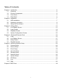
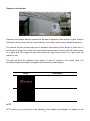
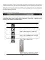
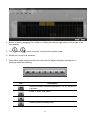
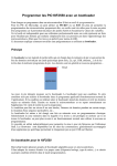
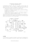
Qguard NVR/CMS ANVR832/ANVR864 USER MANUAL Version 2.0 About this user manual Before installing and using this NVR unit, please read this user manual carefully. Be sure to keep it handy for later reference. Table of Contents Chapter 1 1.1 1.2 1.3 1.4 Chapter 2 2.1 2.2 Introduction ................................................................................................................ 2 Overview .................................................................................................................... 2 Product Components ................................................................................................. 5 Front Panel................................................................................................................. 5 Rear Panel ................................................................................................................. 6 Installation .................................................................................................................. 7 HDD Installation ......................................................................................................... 7 Hardware connection ................................................................................................. 9 2.3 Chapter 3 3.1 3.2 3.3 3.4 Chapter 4 4.1 4.2 Setup NVR via Wizard ............................................................................................... 9 Getting Start ............................................................................................................. 15 Live Display Screen ................................................................................................. 15 Login Screen ............................................................................................................ 19 Playback Screen ...................................................................................................... 20 System Configuration Screen................................................................................... 25 Windows® Remote Client ........................................................................................ 36 Login ........................................................................................................................ 36 Live Display Screen ................................................................................................. 37 4.3 4.4 Chapter 5 5.1 5.2 5.3 5.4 5.5 Emap Screen ........................................................................................................... 44 Playback Screen ...................................................................................................... 45 Advanced System Setup .......................................................................................... 49 Camera Setup .......................................................................................................... 49 Record Setup ........................................................................................................... 56 Event Setup.............................................................................................................. 59 Account Setup .......................................................................................................... 61 Storage Setup .......................................................................................................... 64 1.6 Network Setup.......................................................................................................... 66 5.7 System Setup ........................................................................................................... 69 5.8 DIO Setup ................................................................................................................ 75 5.9 Log ........................................................................................................................... 77 5.10 Map .......................................................................................................................... 80 Chapter 6 CMS Client………...….……………………………………………………………………..84 1 Chapter 1 Introduction 1.1 Overview Arlotto 32/64 channel Linux NVR server series is powered by newest 64-bit embedded Linux and Intel® GPU H/W decoding technologies with superior stability and performance. Equipped with 8-bay hot-swappable SATA II 3.5” hard disk trays and automatic RAID-5 mode, this NVR system can support most all Arlotto IP cameras for up to 64CH video recording and let you access your recordings quickly and reliably. With Arlotto NVR series, customers can rapidly deploy their IP surveillance application with optimum surveillance and operating efficiency and delivers a better security and stability than the counter-part Windows® powered system. Application Architecture Key Feature Enhanced 64-bit Linux OS, well-protection against viruses and hackers Intel® GPU 1080P, 400FPS hardware H.264 decoding H.264, MPEG-4 and M-JPEG compression Max. 32/64-CH IP cameras recording(supports 5 Megapixel IP camera) Optical and digital PTZ for live view and playback Dual streaming for recording and local/remote/mobile live view NVR software pre-installed on DOM module for rapid system deployment Support analog and SDI digital capture board for hybrid applications CMS and iOS/Android mobile surveillance support 2 Hardware Specification ANVR832 ANVR864 Rack mount NVR 32CH 64CH Intel®Q67 Intel Core i7-2600 3.4GHz,8M cache VGA*1 , DVI *1 , HDMI*1 Audio input*1, Audio output*1 USB2.0 : Front*2, Rear*4 RS232 x 1 , RS232 / 422 / 485(internal) x 1 Gb Ethernet LAN x 2 8 hot-swap SATA bay Above 2 HDD RAID 5 600W ATX / AC 100~240V 535.2mm (W)*440.9mm (D)*88.1mm(H) Software Specification Camera Support Remote Playback - Supported Arlotto and Axis IP Cameras - Playback Mode: Max. 4CH playback - IP cameras auto discovery within LAN - Playback Mode: 1, 2X2 view mode - Video Compression: H.264/ MPEG-4/ M-JPEG - Search Mode: By timeline - Video Resolution: Up to 5 Megapixel - Playback Control: Play, pause, reverse play, previous key - Video Streaming: dual streaming with compression, frame/next frame, speed control(1, 2,4, 8. 16), video resolution, frame rate, bit rate/quality, brightness, snapshot, digital zoom and audio control contrast, hue, saturation and sharpness settings - - Export: Convert recording video to AVI, ASF or MKV format and export to external USB device Channels Support (Recording): allows for up to 32/64CH megapixel IP camera recording Event Management Audio: synchronized audio and video recording, - two-way audio Monitor video motion, digital input, camera disconnected, video loss, storage full, hard disk failure, 3 Recording backup failure, system boot-up, system shutdown and - Recording Speed: Max. 64CH, 1920FPS/HD recording system configuration changed events within specified - Recording Mode: Continuous/motion/alarm time. recording, multiple continuous/motion/alarm - - On-screen event alert, event log, digital output, email recording schedules alert with attached recording video alert actions can be Recording Buffer: Adjustable for pre-event recording activated when an event is triggered and post-event recording, recycle HDD and keep Backup video days - Backup recording video of previous day to ftp server Dual Local Monitor System - Clone mode, two live view mode, live view + playback - Support USB and network firmware upgrade and patch mode - Support remote system shutdown and reboot Local live view - Support remote console management - Display Speed: Max. 32/64CH, 400FPS/HD real-time Security monitoring - - Authority Management: four-level privilege, different user rights can be assigned to different users Display Mode: 1, 2X2, 3X3, 3X4(or 4X4), 6x6, 8X8, sequential and event video view mode - Event Logs: detailed event logs - Display Resolution: 1920X1080 - User Logs: record of the users currently logged on and - Display Control: video snapshot, optical PTZ/digital - previously logged on to the NVR PTZ control and audio control - OSD information: camera name, date/time, Disk Management record/event status - Support HDD S.M.A.R.T. to monitor hard disk drives status - With more than 3 HDD redundant automatic storage with Local Playback Software License Manager - Playback Speed: Max. 16CH playback - Playback Mode: 1, 2X2, 3X3, 3X4(or 4X4) view mode Network - Search Mode: By timeline, motion - - Playback Control: Play, pause, reverse play, previous low bandwidth stream for local, remote or mobile live frame/next frame, speed control(1, 2,4, 8. 16), video view snapshot, digital zoom and audio control - RAID-5 HDD mode, less than 3 HDD no RAID. - Dual streams: high resolution stream for recording and Protocol: HTTP, DHCP, Static IP, DNS, PPPoE, DDNS, FTP, NTP, RDATE, SSH, UPnP and SMTP Export: convert recording video to AVI, ASF or MKV - Timeout period for idle remote client to automatic log off Remote Live View - Outgoing Bandwidth Limit - View Mode: 1, 2X2, 3X3, 3X4 (or4X4), 8X8 and Utility sequential display from multi-site NVR servers - format and export to USB storage simultaneously - OSD information: camera name, date/time, and quick setup IP Camera) - record/event status - - NVR setup wizard (discovery NVR, NVR network setting Windows remote client, iPhone/iPad client and Android client View Control: Full screen display, original video iPhone/iPad and Android app aspect ratio, video snapshot, optical PTZ/digital PTZ - 1, 4 screen division control and audio control - Two-way audio Device Tree: Tree View listing and management - HD live view and event video playback 4 - Event Control: Event List, Digital Input status and - Event push notification digital output control - Snapshot for evident - PTZ, ePTZ control 1.2 Product Components The package contains the main unit and its components as specified below. When you purchase the NVR, please check to ensure the components specified below are included. The NVR unit Screws for disk drives Power cord Warranty card with Serial Number Setup Wizard, Windows® Remote Client, iPhone® app, iPad® app and Android® app 1.3 Front Panel ANVR832/ANVR864 5 ANVR832/ANVR864 1.4 Rear Panel 6 Chapter 2 Installation 2.1 HDD Installation 1. Remote the front cover, open the HDD tray and mount the hard drive ANVR832/ANVR864 2. Mount the hard drive into the HDD tray with screws. 4 screws for each tray, rotate clockwise to fix it. 7 3. Put the HDD tray back. Note: Please install HDDs with the same model and storage capacity for easily maintenance. 8 2.2 Hardware connection 1. Connect one end of the network cable to the gigabit network port. Note: Make sure network port is connected to the network via network cable. They will obtain IP addresses automatically via DHCP by default. You must enable the DHCP function within your network, as the NVR unit will retrieve an IP address through. (The IP Address and Netmask will default to 192.168.1.200, 255.255.255.0 for eth0 and 192.168.1.201, 255.255.255.0 for eth1 in case of no DHCP server existed) 2. Connect the other end of the network cable to your Ethernet hub or switch. 3. 4. 5. 6. Connect the power cord to the power source. Connect the power cord to the rear panel of the NVR unit. On the front panel of the NVR unit, click the power button. It takes about one to two minutes for the NVR unit to fully power up. Once it is powered up, the Power LED will turn blue. 2.3 Setup NVR via Wizard The NVR Setup Wizard (Setup Wizard program) performs the initial setup procedures on the NVR unit. After this procedure, you can begin access NVR via NVR local console or Windows® Remote client. 1. Get the NVR Client installation file. 2. Double-click NVR Client Installation.exe to begin installation. 3. Follow the instruction of NVR Client Installation.exe to install, or click the Exit button to close the installer. 4. Click the Start button -> NVR Remote Client -> Setup Wizard. 9 5. Choose your preferred language and then click the Next button (English, Japanese, Russian, Traditional Chinese) 10 6. Click Search button, the NVR Setup Wizard will start searching for all the available NVRs on the LAN currently. Choose one of them, and then click the Next button. 7. Type in the admin password (default is “1234”), click the OK button and then click the Next button. 11 8. Type in the NVR hostname, http port (default is 80) and eth0/eth1 network setting, and then click the Next button. DHCP IP Setting: obtain IP Address, Netmask, Gateway, Primary DNS Sever and Secondary DNS Server automatically via DHCP Static IP Setting: configure IP Address, Netmask, Gateway, Primary DNS Sever and Secondary DNS Server manually. 9. Add cameras for this server. Click Search to automatically find all IP cameras on the LAN currently. (adjust the Timeout parameter of the left bottom if can’t find any connected IP 12 camera, the default value is 60 seconds) Select the check box next to the desired IP camera or “All” for all IP cameras, and then click Next button. 10. Type in Admin Name and Password of searched IP camera or manually configuring the IP cameras for the Address, Port, Admin Name, Password, CH ID(video server only), Model No. and click Apply and then Next button. 11. click the Exit button to finish the settings procedure and activate the NVR unit. 13 14 Chapter 3 Getting Start After the installation is done, you can begin to operate the NVR unit to monitor, playback the connected IP cameras and manage the functions of the NVR unit via local console. 3.1 Live Display Screen Each time the NVR unit starts, the local console defaults to the live display screen. The following diagram outlines the functions used on the live display screen. You should become familiar with these options as this is the screen that will be displayed the majority of the time. Live display screen 15 Camera view window Camera view window displays camera title bar and its live video stream in a grid. The NVR supports different view modes for these grids, including single, quad, 9-split, 12-split, 16-split and 64-split view modes. Camera information will be shown on the camera title bar; it includes camera name, current date/time, motion alarm and recording status. Icon Description / Camera is being recorded/not being record ed. Camera detects motion. The camera title box and bounding box of camera view window will be shown in white color. It will change to orange color when it becomes as the focus window. Double-click left mouse button on a given grid will enlarge its size and double-click right mouse button on a given gird will reduce its size. The grid will show the live video stream of each IP camera in the normal case. The following background images will appear when abnormal status happens: Image Description This channel is trying to connect to IP ca mera. 16 No response from IP camera. (Network failure or IP camera disconnected.) This channel is unused. ePTZ ePTZ allows you to zoom part of the video stream and enlarge it to display on the camera view window. Press left mouse button and drag a red rectangle over a grid, and then release left mouse button. The red area will be displayed in the full camera view window. Just press left mouse button and drag it within the grid to see other area and scroll the mouse wheel forward to zoom in and backward to zoom out. Double clicking right mouse button will terminate the digital magnifying procedure. Task control bar for live display screen The task control bar locates at the bottom side of live display screen, it will show or hide automatically when moves or leaves mouse to the bottom of the screen. It provides several buttons for easy operate your live display screen: Icon Description Press to logout system and enter the login screen, users can choose to login again or to shutdown the system. Press to enter playback screen. Press to enter system configuration screen. 17 Press to take a snapshot from focused camera view window. Press to auto-switch camera views. Press to show PTZ panel Press to talk with camera Press to listen camera’s audio. Dragging the bar to volume up or volume down or clicking the mute button to enter mute mode. Press to enter single view mode. Press to enter quad view mode. Press to enter 9-split view mode. Press to enter 12-split view mode. Press to enter 16-split view mode. Press to enter other split view modes, incl uding 5x5, 6x6, 7x7, 8x8, 1+2, 1+3, 1+5, 1+7 and 1+12 split view modes. 18 This LED panel shows the IP address, log in user, current connected user, current da te/time, HDD mode and status. PTZ panel For PTZ camera, PTZ panel can control the direction, focal lengths, focus, iris, go to preset and speed of camera. Through camera view window, you can see the live video when navigate PTZ cameras, adjust IRIS, Focus, zoom in and zoom out. Icon 、 、 、 Description 、 、or 、 、 Press arrow on the camera view window t o adjust the TILT (up/down)/PAN (left/right) position. Press / to zoom in/zoom out Press / to adjust the PTZ focus. Press / to adjust the PTZ iris. the PTZ. Speed Press +/- icon to adjust the PTZ speed. Preset Press +/- icon to the preset point, then press Go to the preset point. 3.2 Login Screen The local console is defaults auto-login to the live display screen. Users can disable '' Auto 19 Login'' mechanism and then press Login button to login the system, press Cancel button to cancel or press Shutdown button to shutdown the system by entering correct User Name and Password. (Note: The default administrator: User Name is admin, Password is “1234”). 3.3 Playback Screen This NVR has several search methods that allow the user to easily playback a particular section of recording video. The following describes how to operate these playback features. Playback screen 20 Playback view window Playback view window displays camera title bar and its playback video stream in a grid. Camera information will be shown on the camera title bar, it includes camera name, playback date/time. The camera title box and bounding box of playback view window will be shown in white color. It will change to orange color when it becomes as the focus window. Double-click left mouse button on a given grid will enlarge its size and double-click right mouse button on a given gird will reduce its size. The grid will show the playback video stream of each IP camera in the normal case. The following background images will appear when abnormal cases happen: Image Description No recording clip for the IP camera. This channel is unused. ePTZ ePTZ allows you to zoom part of the playback video stream and enlarge it to display on the 21 playback view window. Press left mouse button and drag a red rectangle over a grid, and then release left mouse button. The red area will be displayed in the full playback view window. Just press left mouse button and drag it within the grid to see other area and scroll the mouse wheel forward to zoom in and backward to zoom out. Double clicking right mouse button will terminate the digital magnifying procedure. Task control bar for playback screen The task control bar locates at the bottom side of playback screen, it will show or hide automatically when moves or leaves mouse to the bottom of the screen. It provides several buttons for easy operate your playback screen. Icon Description Press to back to live display window. Press to quickly find playback video of a certain time period using timeline or motion search. Press to export video of a certain time period using timeline. Press to take a snapshot from focus play back view window. Press to listen camera’s audio. Dragging the bar to volume up or volume down or clicking the mute button to enter 22 mute mode. Press to enter single view mode. Press to enter quad view mode. Press to enter 9-split view mode. Press to enter 12-split view mode. Press to enter 16-split view mode. This LED panel shows the playback speed, playback date/time, HDD mode and status. Timeline Search There are several different types of search methods that can be performed on the NVR unit. The basic one is timeline search involves selecting the date, camera, time and then play. 1. Click the Search button . 2. Select Timeline search from the Search Mode popup menu. 3. Click the Calendar button to pop up or pop down a calendar for selecting a date. 23 4. Select a time by dragging the red bar or clicking the left and right arrows to the right of the time display. 5. The and icons can zoom in and out the timeline scale. 6. Select one, more or all cameras. 7. Click OK to begin search and then the video can be played forwards, backwards, or frame-by-frame as following: Icon Description Press to increase backward speed at 1x, 2x, 4x, 8x and 16 x speeds. Press to back one frame. Press to rewind recorded video. Press to pause recorded video. 24 Press to play recorded video. Press to forward one frame Press to increase forward speed at 1x, 2x, 4x, 8x and 16 x speeds. Motion Search When playback in single split mode, draw a motion detection area can search clips that detected motions within the search area. 1. Draw a motion detection area by pressing mouse left button and dragging an area. Click mouse right button can clear the area that just drew. 2. Click icon to search the next clip 3.4 System Configuration Screen The system configuration screen allows you to setup your NVR unit by adjusting settings like camera, network, system and license. It is extremely important that you setup your NVR correctly. Camera setup 1. Click button, (only administrator and power user has this permission) 2. Enter system configuration screen by typing in correct Password. 25 3. Click Auto Search button to list all the currently available cameras. 4. Select the check box next to the desired camera. 5. Specified the Camera ID for the desired camera. 6. Click Add Camera button to add it into Camera List or Cancel button to cancel the change. 7. Click an available camera on the Camera List. 8. Check Enable to active the video channel. 26 9. Modify the related column on the camera raw or click Edit to modify it furthermore. 10. Click Stream Detect button to get IP camera’s streaming setting. 11. Click Clear button to clear the selected raw or Clear All to clear all cameras setting. 12. Click Reset button to reset the related modifications. 13. Click Apply button to apply the change or Cancel button to cancel the change. 27 Camera streaming setting 1. Click Stream Setup button. 2. Select a stream profile from the stream profiles drop-down menu for NVR Stream 1. 3. Change the default video codec (H.264, MPEG-4 or MJPEG), resolution, frame rate, bit rate/quality setting if needed. Click Submit button to save your changes to IP camera. Note: The available values will vary by camera. 4. Click Apply button to apply the change or click Cancel button to cancel the change. 5. Check NVR Stream 2 if needed. 6. Select a stream profile from the stream profiles drop-down menu for Stream 2. 7. Change the default video codec (H.264, MPEG-4 or MJPEG), resolution, frame rate, bit rate/quality setting if needed. Click Submit button to save your changes to IP camera. Note: The available values will vary by camera. 8. Click Reset button to reset the related modifications or Click Return button to return to previous page. 9. Click Apply button to apply the change or click Cancel button to cancel the change. 28 Camera image setting Clicking the Image tab and then adjust the following sliders to change the camera image: 1. Click Image Adjust button. 2. 3. 4. 5. 6. 7. Bright: move the Brightness slider bar to the right or left to adjust the brightness. Contrast: move the Contrast slider bar to the right or left to adjust the lighting difference between dark and light areas of the image. Saturation: move the Saturation slider bar to the right or left to adjust the overall color intensity of the image. Hue: move the Hue slider bar to the right or left to adjust the color cast of the image. Sharpness: move the Sharpness slider bar to the right or left to adjust the edge contrast of the image. Click Submit button to save your changes to IP camera. Click Default button to reset it to IP camera’s default. Click Reset button to reset the related modifications or Click Return button to return to previous page. 10. Click Apply button to apply the change or click Cancel button to cancel the change. 8. 9. 29 Network Setup To connect NVR to LAN or Internet, you need to: 1. Enter the NVR Host Name, HTTP port (default is 80), Streaming port (default is 8888) 2. Enable SSH (for remote maintenance purpose). 3. If your NVR has two Ethernet ports, make sure both Ethernet ports are connected to the network first and then select dual-IP, Load Balancing or Fail-over mode for the TCP/IP setting: A. Dual-IP: assign different IP settings for each Ethernet channel. 30 B. Load-Balancing: aggregating two Ethernet channels together to form a single channel for network traffic sharing. C. Fail-over: aggregating two Ethernet channels together to form a single channel for redundancy in Ethernet paths. 4. Select one of the following mechanisms to configure the Ethernet channels (eth0, eth1) of NVR: A. DHCP IP setting: obtain IP Address, Netmask, Gateway, Primary DNS Sever and Secondary DNS Server automatically via DHCP server (the IP Address and Netmask will default to 192.168.1.200, 255.255.255.0 for eth0 and 192.168.1.201, 255.255.255.0 for eth1 in case of no DHCP server existed ) B. Static IP Setting: configure IP Address, Netmask, Gateway, Primary DNS Sever and Secondary DNS Server manually. C. PPPoE setting: Enter User Name and Password provided by ISP. The system will return the IP assigned by ISP in case of dialup successfully. 5. Specify Maximum Outgoing Bandwidth to restrict the amount of outgoing bandwidth of NVR uses. 6. DDNS (Dynamic Domain Name Server) allows you to connect NVR with dynamic IP address. You can refer to http://www.no-ip.com/services/managed_dns/free_dynamic_dns.html and register an account, and then: 31 i. ii. iii. iv. Enter your account in User Name field. Enter your password in User Password field. Select the Sync Period to setup interval for IP/DDNS synchronization. The domain name field will return your DDNS name assigned by no-ip when connect successfully. 7. Configure your SMTP here to send event notifications to the E-mail address specified in Event: i. ii. iii. iv. Enter your SMTP server. Enter User Name of SMTP server Enter User Password of SMTP server Enter the sender address of event notifications 8. Click Apply button to apply the change or click Cancel button to cancel the change. 32 System Setup System setup supports NVR management features including: backup/restore configuration file, reset default configuration, ugrade firmware, reboot/shutdown NVR system and language setting. Backup/Load Configuration 1. Click Backup/Load button. 2. Browse a destination/file for backup/load. 3. 4. 5. 6. Click the OK button. A confirmation dialog pops up. Click the OK button to confirm and start backup/load. After configuration load, the NVR will restart automatically. 33 Reset to Default Configuration 1. 2. 3. 4. Click the Reset to Default button. A confirmation dialog pops up. Click the OK button to reset. After configuration load, the NVR will restart automatically. Upgrade firmware 1. Browse the firmware file for upgrading. 2. Click the OK button. 3. A confirmation dialog pops up. 4. Click the OK button to confirm and start upgrade. 5. After upgrade, the NVR will restart automatically. Language setting 1. Select a preferred language. 2. Click Apply button to apply the change or click Cancel button to cancel the change. License Setup Register a license to have more channel capacity for NVR. (Max. 64 channels for each NVR) Licenses can be registered to NVR in two ways: online and offline. 34 Online register 1. 2. 3. 4. 5. 6. Select the Online Register on the License Info column. Enter your Serial Number. NVR will verify Host Info and Random Number and then obtain a License Key via Internet. Click Apply button to register this license info. System will reboot automatically if registered successfully. The new License Info will be updated in License List. 35 Chapter 4 Windows® Remote Client You can also operate the NVR unit via Windows® remote client to monitor, playback the connected IP cameras and manage the functions of the NVR system. 4.1 Login Click the Start button -> NVR Client -> NVR Remote Client at your Windows® desktop. When the client is up, you will see the following login window. Login window Login your NVR unit by entering its NVR Name, IP Address, Port No., User Name, Password, Language and Resolution and then click OK begin using this unit. (Note: The default administrator: User Name is admin, Password is “1234”). After entering the correct information, you will see the live display screen within 10 seconds. 36 Live display screen The entered NVR would be listed in the drop-down menu at the NVR Name field. You can select available NVR units from the drop-down menu during next time you log in and the system will fill in the related fields automatically and you only need to reenter the Password field to login your NVR unit. 4.2 Live Display Screen Upon successful login, the live display screen will be shown. 37 System bar In the system bar, you may see system information including the login user name, the address of the NVR unit you connect to and the following buttons: Icon Description Press to minimize Windows® remote clien t. Press to close Windows® remote client. Press to enter live display screen. Press to enter playback screen. Press to enter setup screen. Camera view window Camera view window displays camera title bar and its live video stream in a grid. The NVR supports different view modes for these grids, including single, quad, 9-split, 12-split, 16-split and 64-split view modes. Camera information will be shown on the camera title bar, it includes camera name, current date/time, motion alarm and recording status. 38 Icon Description / Camera is being recorded/not being record ed. Camera detects motion. The camera title box and bounding box of camera view window will be shown in white color. It will change to orange color when it becomes as the focus window. Double-click left mouse button on a given grid will enlarge its size and double-click right mouse button on a given gird will reduce its size. The grid will show the live video stream of each IP camera in the normal case. The following background images will appear when abnormal status happens: Image Description This channel is trying to connect to IP ca mera. No response from IP camera. (Network fai lure or IP camera disconnected.) This channel is unused. 39 Device panel Device panel shows all the connected devices of NVR. A device can be an NVR, IP camera or a network I/O module. The device node will be shown in red color in case of abnormal. Expanding each device will show subordinate devices, such as sensor input devices or alarm output devices on network I/O modules. Icon Description Normal/Abnormal NVR / Normal/Abnormal IP camera / Normal/Abnormal video server / Normal/Abnormal video channel / Normal/Abnormal network I/O module / Normal/Abnormal sensor input device / Normal/Abnormal alarm output device / 40 Control panel Control panel provides several buttons for control view mode and two-way audio. The status of network I/O modules is also displayed in panel. You can trigger outputs using this panel if network I/O module is connected. Icon Description Press to enter single view mode. Press to enter quad view mode. Press to enter 9-split view mode. Press to enter 12-split view mode. Press to enter 16-split view mode. Press to enter full screen view mode. Press to show video in original aspect ratio. Press to take a snapshot from focus camera view window. Press to auto-switch camera views. Press Up/ Down arrow to adjust the switch interval. (10 seconds as default, max. 30 seconds.) / Listen to camera’s audio, enter mute mode, v olume up or volume down control. Talk to IP camera, volume up or volume down control. 41 Din reflects instant sensor input device status. / stand for normal/abnormal status. Dout reflects instant alarm output device statu s. / stand for normal/abnormal status. PTZ panel For PTZ camera, PTZ panel can control the direction, focal lengths, focus, iris, go to preset and speed of camera. Through camera view window, you can see the live video when navigate PTZ cameras, adjust IRIS, Focus, zoom in and zoom out. Icon Description Press arrow ( 、 、 、 、 、 、 、 or ) to adjust the TILT(up/down)/PAN(left/ right) position. Press to go the default position. Press / to zoom in/zoom out Press / to adjust the PTZ focus. Press / to adjust the PTZ iris. the PTZ. Preset Press Up/Down arrow to the preset point, and then press Go to the preset point. Speed Press Up/Down arrow to adjust the PTZ spe ed. 42 Digital magnifying glass Digital magnifying glass allows you to zoom part of the video stream and enlarge it to display on the camera view window. Click and drag a highlight rectangle over a grid, move the rectangle to a interesting area using mouse and scroll the mouse wheel forward to zoom in and backward to zoom out. Right clicking on this grid will terminate the digital magnifying procedure. Event panel Event panel shows latest events from the NVR or its connected IP cameras, with their status, type, date/time, camera name, description and device IP information. New events are constantly appended to the top of the list and old events will be removed from the list. Icon Description Alarm happen and still exist Alarm happen but disappeared Currently supported event types include video motion, digital input, camera disconnected, video loss, storage full, hard disk failure, abnormal recording, backup failure, system boot-up, system shutdown and system configuration changed events. 43 LED panel The LED panel shows the current date/time, CPU usage, memory usage, HDD mode and status. 4.3 Emap Screen Emap screen allows you to specify a multiple layers of maps to display the locations of NVRs, IP cameras and network I/O modules so administrator can have an idea of where a device is located and their current status. The device icons will be shown as red color on the map and Emap panel when an event is triggered. For a camera device, click camera icon will pop up associated live video window for live surveillance. Emap panel shows all the connected maps and devices of NVR. A device can be an Emap, NVR, IP camera or a network I/O module. The device node will be shown in red color in case of 44 abnormal. Expanding each device will show subordinate devices, such as sensor input devices or alarm output devices on network I/O modules. Icon Description Normal/Abnormal Map / Normal/Abnormal NVR / Normal/Abnormal IP camera / Normal/Abnormal video server / Normal/Abnormal video channel / Normal/Abnormal network I/O module / Normal/Abnormal sensor input device / Normal/Abnormal alarm output device / 4.4 Playback Screen Most of the functions are the same as those seen in live display screen, but there are some differences in the playback screen. 45 Playback screen Search panel There are several different types of search methods that can be performed on the NVR unit. The basic one is timeline search involves selecting the date, camera, time and then play. 14. Select Time Line search from the drop-down menu within the search panel. 15. Click the Calendar button to pop up or pop down a calendar for selecting a date. 16. Select one, more or all cameras. 17. Click OK to begin search. 46 Time line panel Select a time by dragging the red bar or clicking the left and right arrows to the right of the time display. The and icons can zoom in and out the timeline scale. And then the video can be played forwards, backwards, or frame-by-frame as following: Playback control Icon Description Press to increase backward speed at 1x, 2x, 4x, 8x and 16 x speeds. Press to back one I-frame. Press to rewind recorded video. Press to pause recorded video. Press to play recorded video. Press to forward one frame. Press to increase forward speed at 1x, 2x, 4x, 8x and 16 x speeds. 47 LED panel The LED panel will show the playback date/time and the play control information when in playback screen. 48 Chapter 5 Advanced System Setup The Windows remote client allow you to optimize your NVR unit by adjusting settings like camera, record, event, account, storage, network, system, DIO, log and license. It is extremely important that you setup your NVR correctly. 5.1 Camera Setup Camera setup page Cameras can be added to Camera List in two ways: automatic or manual. 49 Automatic add camera 18. Click Auto Search button to bring up the Auto Search popup. 19. Click Search button to list all the currently available cameras. 20. Select the check box next to the desired camera. 21. Specified the channel ID (of video server) for the desired camera. 22. Click Apply button to apply the change or Return button to cancel the change. 23. Click an available camera on the Camera List. 24. Enter the Admin Account and Password. 50 25. Click Apply button to apply the change or Cancel button to cancel the change. 51 Manual add cameras 1. 2. Click a desired camera on the Camera List. Enter the Camera Name. 3. 4. 5. 6. Check Camera Enable and Audio Enable to active the video and audio channel Enter the IP Address and Port on the Device Column. Enter the Admin Account and Password. Select the Vendor and Model for your IP camera or click Detect button to obtain it 7. automatically. Click Apply button to apply the change or Cancel button to cancel the change. Camera streaming setting It defines how IP camera videos should be streamed to NVR unit. Most IP cameras are capable of providing multiple video streams at the same time. We call those video streams as stream profile. Steam profile defines which video codec (H.264, MPEG-4 or MJPEG), resolution, frame rate, bit rate/quality will be pulled from the IP camera. The available stream profiles will vary by camera. By default, NVR pull only one stream (NVR stream 1) from IP camera. If stream 2 is checked then secondary stream will be pulled. You can specify different stream profiles for NVR stream 1 and NVR stream 2 here. This can be helpful when recording (stream 1) and live view (stream 2) is to be done in different stream profiles for optimizing. 52 10. Select a stream profile from the stream profiles drop-down menu for NVR Stream 1. 11. Change the default video codec (H.264, MPEG-4 or MJPEG), resolution, frame rate, bit rate/quality setting if needed. Click Submit button to save your changes to IP camera. Note: The available values will vary by camera. 12. Click Apply button to apply the change or click Cancel button to cancel the change. 13. Check NVR Stream 2 tab if needed. 14. Select a stream profile from the stream profiles drop-down menu for NVR Stream 2. 15. Change the default video codec (H.264, MPEG-4 or MJPEG), resolution, frame rate, bit rate/quality setting if needed. Click Submit button to save your changes to IP camera. Note: The available values will vary by camera. 16. Click Apply button to apply the change or click Cancel button to cancel the change. 53 Camera image setting Clicking the Image tab and then adjust the following sliders to change the camera image: 11. Bright: move the Bright slider bar to the right or left to adjust the brightness. 12. Contrast: move the Contrast slider bar to the right or left to adjust the lighting difference between dark and light areas of the image. 13. Hue: move the Hue slider bar to the right or left to adjust the color cast of the image. 14. Saturation: move the Saturation slider bar to the right or left to adjust the overall color intensity of the image. 15. Sharpness: move the Sharpness slider bar to the right or left to adjust the edge contrast of 16. 17. 18. 19. the image. Click Submit button to save your changes to IP camera. Click Default button to reset it to IP camera’s default. Click Cancel button to cancel the change. Click Apply button to apply the change or click Cancel button to cancel the change. Define a generic RTSP IP camera RTSP is the most popular video streaming protocol for IP camera, therefore we provides an interface for the users to enter the RTSP URL of IP cameras in order to receive the RTSP video streaming data from the IP cameras and live view, record, and playback the video of the IP cameras on the NVR. 54 The setup procedure is as following: 1. 2. 3. 4. 5. 6. Select camera setup page. Select a Camera within Camera List area. Enter the Camera Name Enter IP address, Port, Admin Account and Password. Define your camera Vendor and Model as “Generic”. Click Apply button to apply the change or click Cancel button to cancel the change. 7. Select Streaming Tab. 8. Specify the RTSP URL for your IP camera. 9. Specify the transport protocol (TCP, UDP or HTTP). 10. Click Apply button to apply the change or click Cancel button to cancel the change. 55 5.2 Record Setup The record setup page allows you to create different recording schedules based on the day, time, and type of recording desired. Record setup page 56 1. Select a camera for recording. 2. Select Copy To Cameras for copy current settings to other cameras. 3. Select Always, Event, Schedule or No Record mode. Note: For event record mode, the camera will begin recording when NVR detects motion o from cameras (can be the same or other cameras) or digital input of network I/O modules. 4. Specify how many days of record data are going to be kept in storage, which will not be removed when recycling record data. 5. Event record mode: Specify Pre-Alarm Recording time (maximum 30 seconds), Post-Alarm Recording time (maximum 30 seconds) and event sources (motion or digital input). 57 6. Schedule record mode: Press left mouse button, drag a red rectangle over the Week Schedule area to specify a week day/time frame and then release the mouse button. Click the Add button to fill blue bars within the time frame for recording. Click any blue bar (the blue bar will be shown with yellow border), click the Modify button and then change from / to time for schedule modification. Click any blue bar (the blue bar will be shown with yellow border), click the Delete button to remove the schedule. Click the Delete All button to remove all schedules. 7. Click Apply button to apply the change or click Cancel button to cancel the change. 58 5.3 Event Setup The NVR unit can handle events of various types. They can be video motion, camera disconnected, video loss and digital input, but also system events like storage full, hard disk failure, abnormal recording, backup failure, system boot-up, system shutdown and system configuration changed events. Event setup page Add an event 1. Click Add button. 59 2. Select the Event Type from the drop-down menu. 3. Select the Source in case of video motion, camera disconnected, video loss and digital input events. 4. Enable the Schedule and specify the start/end time if the event can only be triggered within specified time. 5. Specify the event actions including event log, digital output (the delay time and duration time can be specified) and email alert with attached recording video (the clip length can be specified). 6. Click Apply button to apply the change to Event Setup List or click Cancel button to cancel the change. Modify an event 1. 2. 3. 4. Select an Event Setup on the Event Setup List column. Click Modify button Modify the Schedule and Action columns setting. Click Apply button to apply the change to Event Setup List or click Cancel button to cancel the change. Delete an event or Delete all events 1. 2. 4. Select an Event Setup on the Event Setup List column. Click Delete button or Delete All button Click Apply button to apply the change to Event Setup List or click Cancel button to cancel the change. 60 5.4 Account Setup The account setup is set to provide individual user role-based permissions, including access rights on specific channels while live view, playback, export, backup, PTZ control, DI/DO control, password change, Emap access, view/change setup. You can setup user accounts with different permissions. The NVR supports four types user account: Account setup page 1. Administrator: the administrator account is “admin”. (Default password: 1234). It has the rights of live view, playback and setup. The admin account cannot be deleted. They have the rights to create and delete super users, normal users and guest users, and change their passwords. 2. Power user: power users can be granted the same rights as administrator or just be granted partial administrator rights. They can be deleted by administrator. 3. Normal user: normal users can be granted the rights of live view, playback, change password and view setup. They have no administration authority. 4. Guest user: guest users can be granted the rights as normal users except the right of change password. 61 Add a user 1. Click Add button. 2. Fill in User Name, Password, Reconfirm (password must be typed twice for confirmation purposes), Type (administrator, power user, normal user or guest user), Enable (check this box to enable this account), and idle client timeout period (disconnected if remote client idle more than this period) information for the new account. 3. Select channels that the user has access rights. 62 4. Specify the permissions for specified channels including live view, playback, export, backup, PTZ control, DI/DO control, password change, Emap access, view/change setup for the specified channels. 5. Click Apply button to apply the change to Account List or click Cancel button to cancel the change. Modify a user 1. 2. 3. Select a user on the Account List column. Click Modify button. Modify the related account information setting. 63 4. Click Apply button to apply the change to Account List or click Cancel button to cancel the change. Delete a user 1. 2. 3. Select an user on the Account List column. Click Delete button. Click Apply button to apply the change to Account List or click Cancel button to cancel the change. 5.5 Storage Setup Storage setup page shows all information related to HDD Drives installed on the NVR, it including: 1. HDD mode: RAID or non-RAID mode (independent HDD mode). The RAID level depends on the number of HDD installed if in RAID mode: HDD number Mode 1-2 NO RAID 3-8 RAID-5 Storage setup page 64 Note: A. RAID is short for redundant array of independent (or inexpensive) disks. It is a category of disk drives that employ two or more drives in combination for fault tolerance and performance. B. RAID-5 (Block Interleaved Distributed Parity): Level 5 provides data striping at the byte level and also stripe error correction information. This results in excellent performance and good fault tolerance. 2. Show all installed hard disks, their status, capacity and free size. 3. The summary column will show the total storage capacity, status and RAID rebuild progress in case of rebuild RAID. Change HDD mode 1. Select independent mode or RAID mode. 2. Check Auto-Format to format any new installed or crashed HDD when boot NVR. 3. Check Record Recycle to enable recycling record data if HDD full. 4. Click Apply button, the system will reboot immediately to apply the change or click Cancel button to cancel the change. HDD SMART Select a HDD tab to monitor the health, temperature, and status of the hard disk drives by the S.M.A.R.T. (Self-Monitoring, Analysis, and Reporting Technology). 65 5.6 Network Setup Network setup page To connect NVR to LAN or Internet, you need to: 9. Enter the NVR Host Name, HTTP port (default is 80), Streaming port (default is 8888) 10. Enable SSH (for remote maintenance purpose). 11. If your NVR has two Ethernet ports, make sure both Ethernet ports are connected to the network first and then select dual-IP, Load Balancing or Fail-over mode for the TCP/IP setting: 66 D. E. Dual-IP: assign different IP settings for each Ethernet channel. Load-Balancing: aggregating two Ethernet channels together to form a single channel for network traffic sharing. F. Fail-over: aggregating two Ethernet channels together to form a single channel for redundancy in Ethernet paths. 12. Select one of the following mechanisms to configure the Ethernet channels (eth0, eth1) of NVR: D. DHCP IP setting: obtain IP Address, Netmask, Gateway, Primary DNS Sever and Secondary DNS Server automatically via DHCP server (the IP Address and Netmask will default to 192.168.1.200, 255.255.255.0 for eth0 and 192.168.1.201, 255.255.255.0 for eth1 in case of no DHCP server existed ) E. Static IP Setting: configure IP Address, Netmask, Gateway, Primary DNS Sever and Secondary DNS Server manually. F. PPPoE setting: Enter User Name and Password provided by ISP. The system will return the IP assigned by ISP in case of dialup successfully. 13. Specify Maximum Outgoing Bandwidth to restrict the amount of outgoing bandwidth of NVR uses. 14. DDNS(Dynamic Domain Name Server) allows you to connect NVR with dynamic IP address. You can refer to http://www.no-ip.com/services/managed_dns/free_dynamic_dns.html and register an account, and then: 67 i. ii. iii. iv. Enter your account in User Name field. Enter your password in User Password field. Select the Sync Period to setup interval for IP/DDNS synchronization. The domain name field will return your DDNS name assigned by no-ip when connect successfully. 15. Configure your SMTP here to send event notifications to the E-mail address specified in Event: 68 i. ii. iii. iv. Enter your SMTP server. Enter User Name of SMTP server Enter User Password of SMTP server Enter the sender address of event notifications 16. Click Apply button to apply the change or click Cancel button to cancel the change. 5.7 System Setup System setup page is used to show system information, modify time zone/system time, backup data, control local console and system maintenance. 69 Show System Information The system information tab shows the following items. • • • • Model Firmware Version Camera Capacity MAC Address • • • • • System Temperature System Memory CPU Temperature CPU Fan Speed CPU Usage 70 Modify Time Zone/System Time 1. 2. 3. 4. 5. 6. 7. Select current Time Zone from the drop-down menu. Specify current year, month and day from the calendar. Specify current time and click Apply Time button to apply the change. (the default time is set according to the real-time clock on server. Select the mechanism for time sync. (sync with an Internet NTP or Rdate time server automatically. Enter the IP address or the domain name of the NTP or Rdate server in the Time Server 1 – Time Server5 field and fill in the sync period. (NVR can be configured as the NTP server for the IP cameras or other servers. To ensure the date and time of the IP cameras are synchronized with the NVR, enter the NVR IP as the NTP server of the IP cameras.) Click Logs button to retrieve the time sync log. Click Apply button to apply the change or click Cancel button to cancel the change. 71 Backup Data The NVR can backup recording video of previous day to ftp server as following: 1. Enter the IP address of FTP server. 2. Enter the User Name and Password. 3. 4. 5. 6. 7. Set up the Backup Path for backup files. Enter the Backup Storage Capacity. Enter the Start Time for backup Select the cameras for backup Click Apply button to apply the change or click Cancel button to cancel the change. 72 Local Console The NVR can supports VGA or HDMI output with 1920X1080 resolution. Windows client can perform some remote settings for local console, such as enable it, view mode/dwell interval, event video/dwell video and OSD. 1. 2. 3. 4. 5. 6. 7. 8. Check Enable to enable local console. Select View Mode. (default is 2X2) Enter the Dwell Interval for auto switch. Enable show Event Video when event triggered. Enter the Dwell Interval for Event Video. Check Enable to enable OSD. (default: checked) Select the OSD position. (top or bottom) Click Apply button to apply the change or click Cancel button to cancel the change. System Maintenance Windows client supports several remote NVR management features including: backup/restore configuration file, reset default configuration, upgrade firmware and reboot/shutdown NVR system. 73 Backup/Load Configuration 7. Click Backup/Load button. 8. Browse a destination/file for backup/load. 9. Click the OK button. 10. A confirmation dialog pops up. 11. Click the OK button to confirm and start backup/load. 12. After configuration load, the NVR will restart automatically. Reset to Default Configuration 5. Click the Reset to Default button. 6. A confirmation dialog pops up. 7. Click the OK button to reset. 8. After configuration load, the NVR will restart automatically. Upgrade firmware 3. Browse the firmware file for upgrading. 4. Click the OK button. 5. A confirmation dialog pops up. 74 6. Click the OK button to confirm and start upgrade. 7. After upgrade, the NVR will restart automatically. 5.8 DIO Setup The NVR can handle the digital input/relay output devices via AP-SIO20 network I/O module. Digital input/alarm output devices are connected directly with AP-SIO20 network I/O module, and digital input/alarm output signals are converted to Ethernet through AP-SIO20 network I/O module. DIO setup page 75 Add a network I/O module 1. Click Add button. 2. Select Model of network I/O module from the drop-down menu. 3. 4. Specify the IP Address for network I/O module. Specify the Din port (default is 103) and Dout port (default is 102). 5. Specify the name and NC/NO connection for each digital input device.(blue LED stand for normal status, red LED stand for abnormal status) Specify the name for each relay output device and click ON/OFF button to turn on/turn off relay output device. (blue LED stand for turn off, red LED stand for turn on) Click Apply button to apply the change to DIO List or click Cancel button to cancel the change. 6. 7. Modify a network I/O module 1. Select a network I/O module on the DIO List column. 2. Click Modify button 3. Modify the DIO Info column setting. 4. Click Apply button to apply the change to DIO List or click Cancel button to cancel the change 5. 76 Delete a network I/O module or Delete all network I/O modules 1. Select an network I/O module on the DIO List column. 2. Click Delete button or Delete All button 3. Click Apply button to apply the change to DIO List or click Cancel button to cancel the change. 5.9 Log The Log setup page shows recent event and login logs. In case of abnormal event or system malfunction, the logs can be searched to analyze the related events or system problems. Log page 77 1. Select Event or Login log. 2. Specify Event Type (event types include video motion, digital input, camera disconnected, video loss, storage full, hard disk failure, abnormal recording, backup failure, system boot-up, system shutdown and system configuration changed events) or Login’s username and source (local or remote). 3. Specify the search time range. 4. Click Search button will show the results in Log List column. 5.10 License Register a license to have more channel capacity for NVR. (Max. 64 channels for each NVR) Licenses can be registered to NVR in two ways: online and offline. 78 License page Online register 7. Select the Online Register on the License Info column. 8. Enter your Serial Number. 9. NVR will verify Host Info and Random Number and then obtain a License Key via Internet. 10. Click Apply button to register this license info. 11. System will reboot automatically if registered successfully. 12. The new License Info will be updated in License List. 79 5.11 Map 1. In the Map page, right-click the E-map at Map Area and select Add Map. 2. Select your top layer map. (The default name for top layer map is Map 0, you can rename it by right client the associated icon at Emap tree panel of right-top corner.) 3. Click Change Map to change map or Delete Map to delete map. 4. Place Camera, NVR, network I/O module, Din, Dout and Map to anywhere on the top layer map by right click on the top layer map and select Add Object. 5. Select an object type and then enter their name, source IP, index and icon. 6. Add a camera object: 80 7. Add a NVR object: 8. Add a network I/O module object: 81 9. Add a Din object: 10. Add a Dout object: 82 11. Add a sub-layer map object: 12. Click Apply button to apply the change or click Cancel button to cancel the change. 83 Chapter 6 CMS Client The CMS client is a multiple NVRs management software. You can operate NVR units via CMS client to monitor, playback the connected NVRs, import multiple-layered maps which display the location of all NVRs, IP cameras, network I/O modules and digital input/output devices and manage the functions of the NVR systems. The powerful software can manage max. 16 NVRs, 256 IP cameras and were specifically designed as an enterprise solution. The look and feel of CMS client is quite similar with NVR Windows® remote client. We’ll mention the difference parts as below. 6.1 Login Click the Start button -> NVR Client -> CMS Client at your Windows® desktop. When the client is up, you will see the following login window. Login window Login your CMS client by entering User Name, Password, Language and then OK begin using this unit. (Note: The default administrator: User Name is admin, Password is “1234”). After entering the correct information, you will see the live display screen within 10 seconds. 6.2 Live Display Screen Please refer to section 4.2 for the details. 84 6.2 Emap Screen Please refer to section 4.3 for the details. 6.3 Playback Screen Please refer to section 4.4 for the details. 6.4 CMS Setup Page NVR setup page NVRs can be added to NVR List in two ways: automatic or manual. Automatic add NVR 1. Click Auto Search button to bring up the Search NVR popup. 85 2. 3. 4. 5. Click Search button to list all the currently available NVRs. Select the check box next to the desired NVR. Click Apply button to apply the change or Return button to cancel the change. Click an available NVR on the NVR List. 6. Click Apply button to apply the change or Cancel button to cancel the change. Manual add NVRs 1. Click a desired NVR on the NVR List. 2. Enter the NVR Name. 3. Enter the IP Address and Port. 4. Enter the Login Name and Password. 5. Check Alarm Auto-report to enable the event report of associated NVR. 6. Enter the Channel Number, Din Number and Dout Number of NVR capacity column. 7. Click Apply button to apply the change or Cancel button to cancel the change. Account setup page The account setup is set to provide individual user role-based permissions, including access 86 rights on specific channels, Dins and Douts. Add a user 1. Click Add button. 2. Fill in User Name, Password. 3. Select NVR that the user has access rights. 4. Specify the permissions for specified channels, Dins and Douts. 5. Click Apply button to apply the change to Account List or click Cancel button to cancel the change. Modify a user 5. Select a user on the Account List column. 6. Click Modify button. 7. 8. Modify the related account information setting. Click Apply button to apply the change to Account List or click Cancel button to cancel the change. Delete a user 4. Select n user on the Account List column. 5. Click Delete button. 6. Click Apply button to apply the change to Account List or click Cancel button to cancel the change. Event setup page The event setup page shows recent event logs. In case of abnormal event or system malfunction, the logs can be searched to analyze the related events or system problems. 87 1. Check the Search Condition. 2. Specify the Start Time and End Time for search time range. 3. Specify NVR unit and Event type (event types include video motion, digital input, camera disconnected, video loss, storage full, hard disk failure, abnormal recording, backup failure, system boot-up, system shutdown and system configuration changed events) and camera number. 4. Specify the search time range. 5. Click Search button will show the results in Event List column. Emap setup page Please refer to section 5.11 for the details. 88