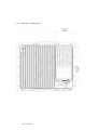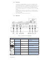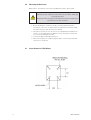
1
DRAFT - 16 September 2014
Instruction Manual
HMI and Visualisation
September 2014
INM 19-102156 A
Azonix Barracuda 15”
Rugged Zone 2 Workstation
DRAFT - 16 September 2014
Customer Service
Mailing Address:
Eaton Experience Center
Azonix Houston Service Center
3413 North Sam Houston Parkway West
Suite 200
Houston Texas 77086
Tel: 866-929-6649
Technical Support:
Visit our site at:
http://www.azonix.com/support
© 2014 Azonix Corporation. All rights reserved.
The information in this user’s manual is provided for reference only. Azonix does not assume any
liability arising out of the application or use of the information or products described herein. This
user’s manual may contain or reference information and products protected by copyrights or patents
and does not convey any license under the patent rights of Azonix, nor the rights of others.
All trademarks, registered trademarks, and trade names used in this user’s manual are the property
of their respective owners. All rights reserved. Printed in the United States of America and Canada.
This user’s manual contains information proprietary to Azonix. Customers may reprint and use this
user’s manual in other publications. Customers may alter this user’s manual and publish it only after
they remove the Azonix name, cover, and logo.
Azonix reserves the right to make changes without notice in product or component design as
warranted by evolution in user needs or progress in engineering or manufacturing technology.
Changes which affect the operation of the unit will be documented in the next revision of this user’s
manual.
ii
INM 19-102156 A
DRAFT - 16 September 2014
CONTENTS
1
USER INFORMATION . . . . . . . . . . . . . . . . . . . . . . . . . . . . . . . . . . . . . . . . . . . . . . . . . . . . . . . 1
1.1
1.2
1.3
1.4
1.5
1.6
1.7
1.8
1.9
1.10
1.11
2
About this Product. . . . . . . . . . . . . . . . . . . . . . . . . . . . . . . . . . . . . . . . . . . . . . . . . . . . . . . . . . . . . . . . . . . . . . . 1
About this User’s Manual . . . . . . . . . . . . . . . . . . . . . . . . . . . . . . . . . . . . . . . . . . . . . . . . . . . . . . . . . . . . . . . . . 1
Customer Comments. . . . . . . . . . . . . . . . . . . . . . . . . . . . . . . . . . . . . . . . . . . . . . . . . . . . . . . . . . . . . . . . . . . . . 1
Trademarks. . . . . . . . . . . . . . . . . . . . . . . . . . . . . . . . . . . . . . . . . . . . . . . . . . . . . . . . . . . . . . . . . . . . . . . . . . . . . 1
Copyright Notice. . . . . . . . . . . . . . . . . . . . . . . . . . . . . . . . . . . . . . . . . . . . . . . . . . . . . . . . . . . . . . . . . . . . . . . . . 1
Standards . . . . . . . . . . . . . . . . . . . . . . . . . . . . . . . . . . . . . . . . . . . . . . . . . . . . . . . . . . . . . . . . . . . . . . . . . . . . . . 1
Manual Part Number:. . . . . . . . . . . . . . . . . . . . . . . . . . . . . . . . . . . . . . . . . . . . . . . . . . . . . . . . . . . . . . . . . . . . . 1
Technical Support. . . . . . . . . . . . . . . . . . . . . . . . . . . . . . . . . . . . . . . . . . . . . . . . . . . . . . . . . . . . . . . . . . . . . . . . 2
Warranty Policy. . . . . . . . . . . . . . . . . . . . . . . . . . . . . . . . . . . . . . . . . . . . . . . . . . . . . . . . . . . . . . . . . . . . . . . . . . 2
Unpacking and Inspecting. . . . . . . . . . . . . . . . . . . . . . . . . . . . . . . . . . . . . . . . . . . . . . . . . . . . . . . . . . . . . . . . . 3
Customer Support and Return Instructions. . . . . . . . . . . . . . . . . . . . . . . . . . . . . . . . . . . . . . . . . . . . . . . . . . . 4
GETTING STARTED . . . . . . . . . . . . . . . . . . . . . . . . . . . . . . . . . . . . . . . . . . . . . . . . . . . . . . . . . . . . . . . . . 6
2.1
2.2
2.3
2.4
2.5
2.6
3
Barracuda™. . . . . . . . . . . . . . . . . . . . . . . . . . . . . . . . . . . . . . . . . . . . . . . . . . . . . . . . . . . . . . . . . . . . . . . . . . . . . 6
Features. . . . . . . . . . . . . . . . . . . . . . . . . . . . . . . . . . . . . . . . . . . . . . . . . . . . . . . . . . . . . . . . . . . . . . . . . . . . . . . . 6
Checklist . . . . . . . . . . . . . . . . . . . . . . . . . . . . . . . . . . . . . . . . . . . . . . . . . . . . . . . . . . . . . . . . . . . . . . . . . . . . . . . 7
Options . . . . . . . . . . . . . . . . . . . . . . . . . . . . . . . . . . . . . . . . . . . . . . . . . . . . . . . . . . . . . . . . . . . . . . . . . . . . . . . . 7
Certifications. . . . . . . . . . . . . . . . . . . . . . . . . . . . . . . . . . . . . . . . . . . . . . . . . . . . . . . . . . . . . . . . . . . . . . . . . . . . 7
Industry Canada. . . . . . . . . . . . . . . . . . . . . . . . . . . . . . . . . . . . . . . . . . . . . . . . . . . . . . . . . . . . . . . . . . . . . . . . . 8
INTRODUCTION. . . . . . . . . . . . . . . . . . . . . . . . . . . . . . . . . . . . . . . . . . . . . . . . . . . . . . . . . . . . 9
3.1
3.1.1
3.1.2
3.1.3
3.1.4
3.1.5
3.1.6
Product Description . . . . . . . . . . . . . . . . . . . . . . . . . . . . . . . . . . . . . . . . . . . . . . . . . . . . . . . . . . . . . . . . . . . . . . 9
Front View and Layout Dimensions. . . . . . . . . . . . . . . . . . . . . . . . . . . . . . . . . . . . . . . . . . . . . . . . . . . . . . . . . . 9
Side View – Workstation. . . . . . . . . . . . . . . . . . . . . . . . . . . . . . . . . . . . . . . . . . . . . . . . . . . . . . . . . . . . . . . . . . 10
Rear View – Workstation . . . . . . . . . . . . . . . . . . . . . . . . . . . . . . . . . . . . . . . . . . . . . . . . . . . . . . . . . . . . . . . . . 11
Bottom View - Workstation. . . . . . . . . . . . . . . . . . . . . . . . . . . . . . . . . . . . . . . . . . . . . . . . . . . . . . . . . . . . . . . . 12
Top View – Workstation . . . . . . . . . . . . . . . . . . . . . . . . . . . . . . . . . . . . . . . . . . . . . . . . . . . . . . . . . . . . . . . . . . 12
Sun Shade and Yoke (Custom Option Only). . . . . . . . . . . . . . . . . . . . . . . . . . . . . . . . . . . . . . . . . . . . . . . . . 13/14
3.2
Connectors . . . . . . . . . . . . . . . . . . . . . . . . . . . . . . . . . . . . . . . . . . . . . . . . . . . . . . . . . . . . . . . . . . . . . . . . . . . . 15
3.2.1 Workstation. . . . . . . . . . . . . . . . . . . . . . . . . . . . . . . . . . . . . . . . . . . . . . . . . . . . . . . . . . . . . . . . . . . . . . . . . . . 15
3.2.2 Connector Pinouts. . . . . . . . . . . . . . . . . . . . . . . . . . . . . . . . . . . . . . . . . . . . . . . . . . . . . . . . . . . . . . . . . . . 16/17
3.3
Front Panel . . . . . . . . . . . . . . . . . . . . . . . . . . . . . . . . . . . . . . . . . . . . . . . . . . . . . . . . . . . . . . . . . . . . . . . . . . . . 18
3.4
3.4.1
3.4.2
3.4.3
3.4.4
3.4.5
4
Specifications. . . . . . . . . . . . . . . . . . . . . . . . . . . . . . . . . . . . . . . . . . . . . . . . . . . . . . . . . . . . . . . . . . . . . . . . . . 19
Workstation System Board Specifications. . . . . . . . . . . . . . . . . . . . . . . . . . . . . . . . . . . . . . . . . . . . . . . . . . . . 19
Flat-Panel Native Display Specifications. . . . . . . . . . . . . . . . . . . . . . . . . . . . . . . . . . . . . . . . . . . . . . . . . . . . . . 20
Power-Supply Specifications . . . . . . . . . . . . . . . . . . . . . . . . . . . . . . . . . . . . . . . . . . . . . . . . . . . . . . . . . . . . . . 20
Barracuda Overall Physical-Dimensions. . . . . . . . . . . . . . . . . . . . . . . . . . . . . . . . . . . . . . . . . . . . . . . . . . . . . . 21
Installation/Certification Requirements . . . . . . . . . . . . . . . . . . . . . . . . . . . . . . . . . . . . . . . . . . . . . . . . . . . . . . 21
INSTALLING THE BARRACUDA. . . . . . . . . . . . . . . . . . . . . . . . . . . . . . . . . . . . . . . . . . . . . . . . . . . . . . . 22
4.1
4.2
4.3
4.4
4.5
5
Before Installation. . . . . . . . . . . . . . . . . . . . . . . . . . . . . . . . . . . . . . . . . . . . . . . . . . . . . . . . . . . . . . . . . . . . . . .22
Guidelines. . . . . . . . . . . . . . . . . . . . . . . . . . . . . . . . . . . . . . . . . . . . . . . . . . . . . . . . . . . . . . . . . . . . . . . . . . . 22/23
Mounting the Barracuda . . . . . . . . . . . . . . . . . . . . . . . . . . . . . . . . . . . . . . . . . . . . . . . . . . . . . . . . . . . . . . . . . 24
Screw Pattern for VESA Mount. . . . . . . . . . . . . . . . . . . . . . . . . . . . . . . . . . . . . . . . . . . . . . . . . . . . . . . . . . . . 24
Starting the System. . . . . . . . . . . . . . . . . . . . . . . . . . . . . . . . . . . . . . . . . . . . . . . . . . . . . . . . . . . . . . . . . . . . . 25
BIOS. . . . . . . . . . . . . . . . . . . . . . . . . . . . . . . . . . . . . . . . . . . . . . . . . . . . . . . . . . . . . . . . . . . . . . . . . . . . . 26
5.1
5.2
5.3
5.4
6
Entering the BIOS Setup Utility. . . . . . . . . . . . . . . . . . . . . . . . . . . . . . . . . . . . . . . . . . . . . . . . . . . . . . . . . . . . 26
Using the BIOS Setup Utility. . . . . . . . . . . . . . . . . . . . . . . . . . . . . . . . . . . . . . . . . . . . . . . . . . . . . . . . . . . . . . 26
Obtaining Help . . . . . . . . . . . . . . . . . . . . . . . . . . . . . . . . . . . . . . . . . . . . . . . . . . . . . . . . . . . . . . . . . . . . . . . . . 27
Troubleshooting the BIOS. . . . . . . . . . . . . . . . . . . . . . . . . . . . . . . . . . . . . . . . . . . . . . . . . . . . . . . . . . . . . . . . 27
Horn Installation. . . . . . . . . . . . . . . . . . . . . . . . . . . . . . . . . . . . . . . . . . . . . . . . . . . . . . . . . . . . . . . . . . . 28
6.1
6.2
6.3
6.4
Overview. . . . . . . . . . . . . . . . . . . . . . . . . . . . . . . . . . . . . . . . . . . . . . . . . . . . . . . . . . . . . . . . . . . . . . . . . . . . . . 28
Operation. . . . . . . . . . . . . . . . . . . . . . . . . . . . . . . . . . . . . . . . . . . . . . . . . . . . . . . . . . . . . . . . . . . . . . . . . . . . . . 29
Installation. . . . . . . . . . . . . . . . . . . . . . . . . . . . . . . . . . . . . . . . . . . . . . . . . . . . . . . . . . . . . . . . . . . . . . . . . . . . . 29
Precautions. . . . . . . . . . . . . . . . . . . . . . . . . . . . . . . . . . . . . . . . . . . . . . . . . . . . . . . . . . . . . . . . . . . . . . . 30/31/32
INM 19-102156 A
iii
DRAFT - 16 September 2014
7
Troubleshooting. . . . . . . . . . . . . . . . . . . . . . . . . . . . . . . . . . . . . . . . . . . . . . . . . . . . . . . . . . . . . . . . . . . 33
7.1
7.2
7.3
7.4
7.5
7.6
7.7
7.8
7.9
7.10
7.11
7.12
8
Maintenance. . . . . . . . . . . . . . . . . . . . . . . . . . . . . . . . . . . . . . . . . . . . . . . . . . . . . . . . . . . . . . . . . . . . . . 39
8.1
8.2
8.3
8.4
8.5
9
Working with Connectors and Cables . . . . . . . . . . . . . . . . . . . . . . . . . . . . . . . . . . . . . . . . . . . . . . . . . . . . . . 39
Handling the Flat-Panel Display . . . . . . . . . . . . . . . . . . . . . . . . . . . . . . . . . . . . . . . . . . . . . . . . . . . . . . . . . . . 39
Working with System Power. . . . . . . . . . . . . . . . . . . . . . . . . . . . . . . . . . . . . . . . . . . . . . . . . . . . . . . . . . . . . . 39
Cleaning the Glass Display . . . . . . . . . . . . . . . . . . . . . . . . . . . . . . . . . . . . . . . . . . . . . . . . . . . . . . . . . . . . . . . 40
Cleaning the Barracuda Casing. . . . . . . . . . . . . . . . . . . . . . . . . . . . . . . . . . . . . . . . . . . . . . . . . . . . . . . . . . . . 40
System Resources. . . . . . . . . . . . . . . . . . . . . . . . . . . . . . . . . . . . . . . . . . . . . . . . . . . . . . . . . . . . . . . . . 41
9.1
9.2
9.3
10
AT I/O Address Map. . . . . . . . . . . . . . . . . . . . . . . . . . . . . . . . . . . . . . . . . . . . . . . . . . . . . . . . . . . . . . . . . . . . . 41
System Memory Mapping. . . . . . . . . . . . . . . . . . . . . . . . . . . . . . . . . . . . . . . . . . . . . . . . . . . . . . . . . . . . . . . . 42
Interrupt Assignments. . . . . . . . . . . . . . . . . . . . . . . . . . . . . . . . . . . . . . . . . . . . . . . . . . . . . . . . . . . . . . . . . . . 42
Flat-Panel Display Characteristics. . . . . . . . . . . . . . . . . . . . . . . . . . . . . . . . . . . . . . . . . . . . . . . . . . . . . 43
10.1
11
12
Resistive Touchscreen Option. . . . . . . . . . . . . . . . . . . . . . . . . . . . . . . . . . . . . . . . . . . . . . . . . . . . . . . . 46
Overview. . . . . . . . . . . . . . . . . . . . . . . . . . . . . . . . . . . . . . . . . . . . . . . . . . . . . . . . . . . . . . . . . . . . . . . . . . . . . . 46
Projected Capacitance Usage . . . . . . . . . . . . . . . . . . . . . . . . . . . . . . . . . . . . . . . . . . . . . . . . . . . . . . . . . . . . . 46
Durability. . . . . . . . . . . . . . . . . . . . . . . . . . . . . . . . . . . . . . . . . . . . . . . . . . . . . . . . . . . . . . . . . . . . . . . . . . . . . . 47
Precautions. . . . . . . . . . . . . . . . . . . . . . . . . . . . . . . . . . . . . . . . . . . . . . . . . . . . . . . . . . . . . . . . . . . . . . . . . . . . 47
Specifications. . . . . . . . . . . . . . . . . . . . . . . . . . . . . . . . . . . . . . . . . . . . . . . . . . . . . . . . . . . . . . . . . . . . . . . . . . 47
Certificates . . . . . . . . . . . . . . . . . . . . . . . . . . . . . . . . . . . . . . . . . . . . . . . . . . . . . . . . . . . . . . . . . . . . . . . 48
14.1
14.2
14.3
14.4
15
Overview. . . . . . . . . . . . . . . . . . . . . . . . . . . . . . . . . . . . . . . . . . . . . . . . . . . . . . . . . . . . . . . . . . . . . . . . . . . . . . 46
Projected Capacitance Touchscreen Option. . . . . . . . . . . . . . . . . . . . . . . . . . . . . . . . . . . . . . . . . . . . . 46
13.1
13.2
13.3
13.4
13.5
14
Overview. . . . . . . . . . . . . . . . . . . . . . . . . . . . . . . . . . . . . . . . . . . . . . . . . . . . . . . . . . . . . . . . . . . . . . . . . . . . . . 44
Troubleshooting and Quick Reference Guide . . . . . . . . . . . . . . . . . . . . . . . . . . . . . . . . . . . . . . . . 44/45
12.1
13
Typical Start-up Sequence. . . . . . . . . . . . . . . . . . . . . . . . . . . . . . . . . . . . . . . . . . . . . . . . . . . . . . . . . . . . . . . . 33
Installation Problems. . . . . . . . . . . . . . . . . . . . . . . . . . . . . . . . . . . . . . . . . . . . . . . . . . . . . . . . . . . . . . . . . . 33/34
Typical System Problems and Solutions . . . . . . . . . . . . . . . . . . . . . . . . . . . . . . . . . . . . . . . . . . . . . . . . . . . . 35
Screen Image Issues . . . . . . . . . . . . . . . . . . . . . . . . . . . . . . . . . . . . . . . . . . . . . . . . . . . . . . . . . . . . . . . . . . . . 35
BIOS Beep Codes. . . . . . . . . . . . . . . . . . . . . . . . . . . . . . . . . . . . . . . . . . . . . . . . . . . . . . . . . . . . . . . . . . . . . . . 35
System Fails to Power Up. . . . . . . . . . . . . . . . . . . . . . . . . . . . . . . . . . . . . . . . . . . . . . . . . . . . . . . . . . . . . . . . 36
Software Application Program Not Working . . . . . . . . . . . . . . . . . . . . . . . . . . . . . . . . . . . . . . . . . . . . . . . . . 37
Flat Panel Fails to Display . . . . . . . . . . . . . . . . . . . . . . . . . . . . . . . . . . . . . . . . . . . . . . . . . . . . . . . . . . . . . . . . 37
Keyboard Fails to Work Properly. . . . . . . . . . . . . . . . . . . . . . . . . . . . . . . . . . . . . . . . . . . . . . . . . . . . . . . . . . . 37
Mouse Fails to Work Properly. . . . . . . . . . . . . . . . . . . . . . . . . . . . . . . . . . . . . . . . . . . . . . . . . . . . . . . . . . . . . 38
Touch Screen Fails to Work Properly (Resistive Versions Only). . . . . . . . . . . . . . . . . . . . . . . . . . . . . . . . . . 38
Battery Fails. . . . . . . . . . . . . . . . . . . . . . . . . . . . . . . . . . . . . . . . . . . . . . . . . . . . . . . . . . . . . . . . . . . . . . . . . . . . 38
ATEX Certificate of Conformity. . . . . . . . . . . . . . . . . . . . . . . . . . . . . . . . . . . . . . . . . . . . . . . . . . . . . 48/49/50/51
IECEx Certificate of Conformity. . . . . . . . . . . . . . . . . . . . . . . . . . . . . . . . . . . . . . . . . . . . . . . . . . . . . 52/53/54/55
AEx Certificate of Compliance. . . . . . . . . . . . . . . . . . . . . . . . . . . . . . . . . . . . . . . . . . . . . . . . . . . . . . . . 56/57/58
Declaration of Conformity. . . . . . . . . . . . . . . . . . . . . . . . . . . . . . . . . . . . . . . . . . . . . . . . . . . . . . . . . . . . . . 59/60
Document Revision Histiry. . . . . . . . . . . . . . . . . . . . . . . . . . . . . . . . . . . . . . . . . . . . . . . . . . . . . . . . . . 61
LIST OF FIGURES
FIGURE 1
FIGURE 2
FIGURE 3
FIGURE 4
FIGURE 5
FIGURE 6
FIGURE 7
iv
CONNECTOR LAYOUT – WORKSTATION . . . . . . . . . . . . . . . . . . . . . . . . . . . . . . . . . . . . . . . . . . . . . .
BEKA ASSOCIATES LTD HORN . . . . . . . . . . . . . . . . . . . . . . . . . . . . . . . . . . . . . . . . . . . . . . . . . . . . . .
YODA ALARM HORN . . . . . . . . . . . . . . . . . . . . . . . . . . . . . . . . . . . . . . . . . . . . . . . . . . . . . . . . . . . . . .
BEKA HORN INTERNAL POWER CONNECTION TERMINAL . . . . . . . . . . . . . . . . . . . . . . . . . . . . . . .
YODA HORN YO5 ISC INTERNAL POWER CONNECTOR . . . . . . . . . . . . . . . . . . . . . . . . . . . . . . . . . .
WIRING TO AMPHENOL CONNECTOR . . . . . . . . . . . . . . . . . . . . . . . . . . . . . . . . . . . . . . . . . . . . . . . .
CONNECTION TO BARRACUDA 15”, BOTH VERSIONS . . . . . . . . . . . . . . . . . . . . . . . . . . . . . . . . . . .
20
33
33
36
37
37
38
INM 19-102156 A
DRAFT - 16 September 2014
1
USER INFORMATION
1.1
ABOUT THIS PRODUCT
AZONIX Barracuda™ 15” Gen 2 Workstations are sold by the
Azonix Corporation.
1.2
ABOUT THIS USER’S MANUAL
This document provides information about the Barracuda™. No warranty of
suitability, purpose, or fitness is implied. While every attempt has been made
to ensure that the information in this document is accurate, the information
contained within is supplied “as is” and can change without notice.
1.3
Customer Comments
If you have any difficulties using this user’s manual, discover an error, or just
want to provide feedback, please send us a message using our Web site (www.
azonix.com) under “Technical Support.” Detail any errors you find. We will
correct the errors or problems as soon as possible. Thank you.
1.4
Trademarks
Barracuda™ is a trademark of Azonix Corporation. All other product names are
trademarks or registered trademarks of their respective holders.
1.5
Copyright Notice
Copyright © 2014 Azonix Corporation. All rights reserved. No part of this manual
may be reproduced, transmitted, transcribed, stored in a retrieval system, or
translated into any language or computer language, in any form or by any means
(electronic, mechanical, photocopying, recording, or otherwise), without the
written permission of Azonix Corporation.
1.6
Standards
Azonix Corporation is certified to ISO 9001 standards.
1.7
Manual Part Number:
19-102156
INM 19-102156 A
1
DRAFT - 16 September 2014
1.8
Technical Support
If you have technical questions or need assistance in identifying or solving a
problem, the technical support department can assist you with your problems
and provide you with the technical information you require. You can contact
technical support by visiting our Website at http://www.azonix.com/support or call 713-280-3436 or -3417.
When you contact technical support please have the
following information:
•
•
•
•
•
•
•
•
1.9
Azonix Serial number of your system
Azonix Model number of your system
Type and version of your operating system
Type and version of your software program
Peripheral devices connected to your system
Operating Parameters during issue
What messages, if any, are on the screen
Technical Support Link: http://www.azonix.com/support
Warranty Policy
Seller warrants the Products to be new and to be free from defect in
materials, and workmanship and to conform strictly to the specifications,
drawings or samples specified or furnished. All warranties shall survive any
inspection, design approval, delivery, acceptance or payment by Buyer. All
warranties shall run to Buyer, its successors, assignees and original end
users. Seller agrees to repair or replace, at Seller’s option, without expense to
Buyer, excluding transportation and handling costs, Products not conforming
to the foregoing requirements when notified by Buyer during a period of
twelve (12) months after shipment by Seller except for spare parts which are
warranted for ninety (90) days
after shipment.
To invoke the warranty set forth in this Paragraph 7, the Buyer must submit
proof of the defect and at the Buyer’s expense, return the defective Products
to the factory or warehouse designated by the Seller. In no event shall the
Seller be responsible for any claimed defect in the Products sold hereunder
unless written notice identifying such defect shall be received by Seller within
one year after Seller’s shipment of the defective goods.
All repairs shall be made at Seller’s facilities unless otherwise agreed in
writing. Seller shall not be liable or responsible for any general, special or
consequential damages. This warranty shall not apply to (a) any defect or
damage arising from the repair or replacement of equipment or any part
thereof, unless the repair or replacement was made with Seller’s prior
written approval; (b) any equipment not maintained and used in accordance
with proper standards and procedures, including any written instructions
or specifications furnished by Seller; (c) any equipment not manufactured
or designed by Seller; (d) any equipment used in an abnormal manner, for
a purpose or with equipment other than that for which it was intended; (e)
any defect in a design furnished by Buyer; (f) any Product or part thereof
covered by this Agreement which has a design life, under normal usage,
inherently shorter than one (1) year. If Seller notifies Buyer of Seller’s desire
2
INM 19-102156 A
DRAFT - 16 September 2014
to replace, change or add to equipment or parts thereof covered by this
warranty for the purpose of improving such equipment or eliminating a defect
therein, Buyer shall permit Seller to do so, at Seller’s expense, at the earliest
commercially reasonable time. Failure to permit any such replacement or
change shall terminate this warranty. In no event shall any warranty run for
more than a total of twelve (12) months, unless agreed to by Seller, in writing,
whether or not the Product is returned or repaired. Seller does not warrant
any software delivered by Seller to be suitable for any particular use; it is
Buyer‘s responsibility to determine the suitability of delivered software and
documentation for Buyer’s purposes. The above warranty is made only to the
original end user of the equipment covered hereby.
THE WARRANTIES PROVIDED IN THIS PARAGRAPH ARE EXCLUSIVE
AND IN SUBSTITUTION FOR, AND SELLER HEREBY DISCLAIMS, AND
BUYER HEREBY WAIVES, ALL OTHER WARRANTIES AND LIABILITIES
OF SELLER AND ALL CLAIMS AND REMEDIES OF BUYER, EXPRESS
OR IMPLIED, ARISING BY LAW OR OTHERWISE,WITH RESPECT TO
ANY DEFECT IN ANY PRODUCTS, INCLUDING, WITHOUT LIMITATION,
ANY (A) IMPLIED WARRANTY OF MERCHANTABILITY OR FITNESS
FOR USE OR FITNESS FOR A PARTICULAR PURPOSE, (B) ANY IMPLIED
WARRANTY ARISING FROM COURSE OF DEALING OR PERFORMANCE
OR USAGE OF TRADE, AND (C) RECOVERY BASED UPON TORT,
WHETHER OR NOT ARISING FROM SELLER’S NEGLIGENCE AND (4)
ANY RECOVERY BASED UPON DAMAGED PROPERTY, OR OTHERWISE
BASED UPON LOSS OF USE OR PROFIT OR OTHER INCIDENTAL
OR CONSEQUENTIAL DAMAGES. THIS WARRANTY SHALL NOT BE
EXTENDED, ALTERED OR VARIED EXCEPT BY A WRITTEN INSTRUMENT
SIGNED BY SELLER AND BUYER. IN THE EVENT THAT ANY PROVISION
HEREOF SHOULD FOR ANY REASON BE HELD INEFFECTIVE, THE
REMAINDER OF THIS PARAGRAPH SHALL REMAIN IN FULL FORCE AND
EFFECT.
1.10 Unpacking and Inspecting
Inspect the unit for shipping damage. Also check the packing material to ensure that you have found all of the proper cables and accessories. Check your
items against the original order to make sure that all of the items have arrived.
If you have received a damaged unit or device, call your sales representative.
If the damages are the result of shipper mishandling, you need to file a claim
against the carrier who delivered your unit. In this case, save all of the shipping material and paperwork and immediately contact the shipping firm for
information on how to file a claim.
INM 19-102156 A
3
DRAFT - 16 September 2014
1.11
Customer Support and Return Instructions
A return authorization number must be obtained from us prior to your
returning any product.
All returns will receive a Return Material Authorization (RMA) via our web
portal at http://www.azonix.com/support. Select the “Support” tab, then
select the “Secure RMA Portal”. Enter your User Name and Password. If you
do not have a User Name and Password please call our service center at 713280-3436 or -3417 and request one. Once logged in select “Request Service”
and a Web Form will appear to be filled out. Use the serial number drop down
list to select your unit from the inventory. If the unit does not appear in the
list fill in the fields manually. Our system will indicate whether the unit is
Warranty or Non-Warranty. If the unit is Warranty, no method of payment will
need to be entered. Please enter all data requested. When the process has
been completed you will receive a message referencing your RMA number.
Please print a copy of this document and return it with the unit. Maintain a
copy for your records.
Return unit to:
Eaton Experience Center
Azonix Houston Service Center
RMA # xxxxxxxxx (enter your number here)
3413 North Sam Houston Parkway West, Suite 200
Dock 1 or 2
Houston, TX 77086
Should it be necessary to return your unit back to the Azonix Houston Service
Center for servicing, please pack your unit in the original shipping container. If
the original shipping container is no longer available, the unit must be securely
packed to prevent damage during shipment. You must obtain a RMA number
from customer service prior to shipment. The serial number of your unit and
the RMA number must accompany the returned unit.
4
INM 19-102156 A
DRAFT - 16 September 2014
ADVISORY CONVENTIONS
Four types of advisories are used throughout this user’s manual to provide helpful information or to alert you to
the potential for hardware damage or personal injury. They are Notes, Cautions, and Warnings. The following is
an example of each type of advisory. Use caution when servicing any electrical component
NOTE:
A note is used to make helpful information stand out.
IMPORTANT:
An important note indicates information that is important for you to know.
CAUTION / ATTENTION
A CAUTION alert indicates potential damage to hardware and explains how to avoid the problem.
Une AT TENTION indique des dommages potentiels au matériel et explique comment éviter
une telle situation.
WARNING ! / AVERTISSEMENT!
An ELECTRICAL SHOCK WARNING indicates the potential for bodily harm from electrical hazards and
explains how to avoid the problem.
Un AVERTISSEMENT DE CHOC ÉLECTRIQUE indique un risque de lésions corporelles contre les
risques électriques et explique comment éviter le problème.
ALTERNATING CURRENT / MISE À LA TERRE
The Protective Conductor Terminal (Earth Ground) symbol indicates the potential risk of serious
electrical shock due to improper grounding.
Le symbole de Mise à la Terre indique le risque potentiel de choc électrique grave due à la terre
incorrecte.
During operation:
•
Make the relevant instructions available at all times to the operating personnel.
•
Observe safety instructions.
•
Observe national safety and accident prevention regulations.
•
Operate the equipment within its published specification.
• Servicing, maintenance work or repairs not described in this manual must not be performed without prior agreement with the manufacturer.
•
Any damage to this equipment may render its explosion protection null and void.
•
No changes to any of the components that might impair their explosion protection are permitted.
If any information provided here is not clear:
Contact MTL or one of its representatives.
Note: Improper installation and operation of the enclosure can result in the invalidation of the guarantee.
INM 19-102156 A
5
DRAFT - 16 September 2014
2
Getting Started
2.1
BARRACUDA™
These rugged and reliable, stand-alone 15” workstations are designed for
use in harsh industrial conditions. Designed for space-constricted situations,
Barracudas require minimal clearance. They can be set up or mounted almost
anywhere. The VESA 75mm/100mm mounting footprint allows them to be
used with all VESA 75 and 100 arms, brackets and stands. For durability, the
enclosure is a bonded hybrid aircraft grade aluminum/aluminum extrusion
structure, and the touch screen is fully bonded for ultimate protection against
the rigors of hose-down cleaning or inclement weather conditions.
The Barracuda’s light weight and alternative mounting options offer multiple
application possibilities in all environments. For light and heavy industrial use
including HAZLOC areas, the Barracuda offers ultra-reliable operation backed
by hundreds of hours of testing and full compliance with multiple Military and
HAZLOC standards.
The workstation version integrates an Intel® i7 processor or an Intel B810®
processor on an industrial single board computer for full workstation
functionality. The display is passively enhanced for full sunlight viewability.
2.2
FEATURES
The Barracuda offers the following features:
6
•
15.1” XGA 1024 x 768 resolution, Sunlight Viewable LCD with
LED backlights
•
Tempered anti-glare glass/Mylar® resistive touch screen
•
Optional projected capacitance all glass touch screen
•
Dismountable 100-240AC / 12vDC certified power supply
•
Detachable power cord and optional Field wire-able version
•
Rugged and durable for indoor and outdoor usage
•
Front panel user controls
•
Locking Military style I/O connectors
•
Supports standard VESA 75 and 100mm mounting
•
Alternative side mounts for yoke and panel
mounting applications
•
Tough corrosion-resistant powder-coat paint finish
INM 19-102156 A
DRAFT - 16 September 2014
2.3
Checklist
In addition to your Barracuda Gen 2 15” workstation, the shipping carton
should contain the following items:
•
Driver Package
•
Touch screen Drivers (For resistive version only)
•
Barracuda User’s Manual
•
System Board Manual
*All the above on a single CD
2.4
Options
The following optional items are available for use with the
Barracuda Gen 2:
2.5
•
Fiber LAN Multimode with Glass fiber drivers
•
Fiber LAN with Plastic fiber drivers (EoPOF)
•
Second serial port
•
Horn driver board
•
AC source, DC 24V Heaters for -40C operation
•
DC source, DC 24V Heaters for -40C operation
•
DC/DC power supply 9-36VDC
•
Larger capacity 1.8” SSDs
•
Sunshade with yoke mount brackets
•
Boom / chain mount
•
Panel mount option
•
Hard travel case
•
Extended detachable AC power cable
•
Beka horn
•
USB keyboard
Certifications
See Appendix F for the product certificates.
Council Directives:
EMC Directive - 2006/95/EC
Low Voltage Directive - 2006/95/EC
ATEX Directive - 94/9/EC
Standards to which Conformity is declared:
LVD: EN61010-1 (3rd Ed.)
EMC: EN61326 with A1 and A2 Class A
ATEX: EN60079-0, 60079-15 (protection type nA)
INM 19-102156 A
7
DRAFT - 16 September 2014
The Barracuda fulfills the requirements for Group II Category 3 G equipment
in accordance to the ATEX Directive 94/9/EC.
Safety Markings :
IECEx :
Ex nA IIC T3 Gc IP66
North America:
Class1 Zone 2 AEx nA IIC T3 Gc IP66
EUROPE / ATEX:
II 3G Ex nA IIC T3 Gc IP66
Without Heater Option :
With Heater Option :
NOTE:
The above label information is for reference only and may not display the latest
certification level.
FCC Warning :
This is a Class A product. In a domestic environment, this product may cause radio
interference in which case the user may be required to take adequate measures.
This equipment generates, uses and can radiate radio frequency energy, and if not
installed and used in accordance with the manufacturer’s instruction manual, may
cause harmful interference with radio communications. This equipment has been
tested and found to be within the limits for a Class A digital device pursuant to Part15
of the FCC Rules. These limits are designed to provide reasonable protection against
harmful interference when the equipment is operated in a commercial environment.
Operation of this equipment in a residential area is likely to cause harmful interference, in which case you will be required to correct the interference at your expense.
Changes or modifications not expressly approved by the party responsible for
compliance could void the user’s authority to operate the equipment. To meet FCC
requirements, shielded cables are required to connect the device to another Class A
certified device.
2.6
Industry Canada
This Class A digital apparatus complies with Canadian ICES-003.
CET appareil numérique de la classe A est conforme á la norme NMB-003 du Canada.
8
INM 19-102156 A
DRAFT - 16 September 2014
3.1.1
3
INTRODUCTION
3.1
Product Description
Front View and Layout Dimensions
INM 19-102156 A
9
DRAFT - 16 September 2014
3.1.2
Side View – Workstation
10
INM 19-102156 A
DRAFT - 16 September 2014
3.1.3
Rear View – Workstation
Rear View – Workstation
INM 19-102156 A
11
DRAFT - 16 September 2014
12
3.1.4
Bottom View - Workstation
3.1.5
Top View - Workstation
INM 19-102156 A
DRAFT - 16 September 2014
3.1.6
Sun Shade and Yoke (Custom Option Only)
(Preliminary Views)
INM 19-102156 A
13
DRAFT - 16 September 2014
(Preliminary Views)
14
INM 19-102156 A
DRAFT - 16 September 2014
3.2
Connectors
To expand your computing capabilities, your system unit supports a variety
of external peripheral devices. It is equipped with several interface ports in
which to connect these devices. Located on the bottom panel, the connection
ports are labeled for easy hook-up and installation. The Barracuda workstation also provides an Ethernet port for connecting the system into an existing
network.
Thoroughly read the “Precautions” section before connecting any external
peripheral devices to your system. Make sure the unit is turned “Off” before
connecting any cables.
After you make the connections, start the system.
3.2.1
Workstation
Figure 1 - Connector Layout – Workstation
Connectors – Workstation
Icon
Type
Description
Mating Connectors
(Amphenol)
Heater AC Input
3-pin plug shell
PTO6W-12-3SO23
Protective Earth
Ground
14AWG - 2AWG wire
terminal
--
DC Input
4-pin plug shell
PTO6W-12-4SO23
Serial Port
10-pin plug shell
PTO6W-12-10SO23
Ethernet Port
RJ45 jack
RJFTV6MN
USB Port
USB 4-pin type A
USBFTV6N
USB Port
(optional)
USB 4-pin type A
USBFTV6N
INM 19-102156 A
15
DRAFT - 16 September 2014
3.2.2 Connector Pinouts
AC Input and Heater Connector
Pin
Name
A
LINE
B
EARTH
C
NEUTRAL
Pin
Name
Function
A
VIN
+12Vdc to SBC
B
VOUT
+24Vdc to Heater in Power Supply
C
VIN
-12V DC to SBC
D
VOUT
-24Vdc to Heater in Power Supply
Pin
Name
Description
1
VCC
+5 VDC
2
D-
Data-
3
D+
Data+
4
GND
Ground
Pin
Name
Description
1
TX+
Transfer Data+
2
TX-
Transfer Data-
3
RX+
Receive Data+
4
n/c
Not connected
5
n/c
Not connected
6
RX-
Receive Data-
7
n/c
Not connected
8
n/c
Not connected
Pin
Name
Description
C
CTR
Signal
S
SHD
Ground
DC In Connector
DC In Connector
LAN (RJ45) Connector
LAN (RJ45) Connector
16
INM 19-102156 A
DRAFT - 16 September 2014
Serial Connector
Pin
Name
Description
A
DSR
Data set ready
B
DCD
Data carrier detect
C
RTS
Ready to send
D
RXD
Receive data
E
CTS
Clear to send
F
TXD
Transmit data
G
ISO24
Horn plus
H
DTR
Data terminal ready
I
GND
Signal ground
J
ISO Ret
Horn minus
Barracuda 15” WS Serial Port Pin-outs for Alternate Comms formats
Amphenol I/O
Circular Conn
RS232
RS422
A
DSR
RTS -
B
DCD
TX -
C
RTS
RTS +
D
RX
TX +
E
CTS
CTS +
F
TX
RX +
G
(RI) ISO +
(CTS -)
H
DTR
RX -
J
GND
GND
K
ISO -
RS485
Comments
DATA -
DATA +
Horn power
GND
Horn power
Notes: If RS422 CTS or RS232 RI signals are required contact Azonix.
These signals are not available with the Horn option.
INM 19-102156 A
17
DRAFT - 16 September 2014
3.3
Front Panel
LEDs
Icon
Color
Green
Description
Power on LED
Yellow
HDD Active LED
Orange
Heater ON LED
Blue
LCD/Touch OFF LED
Buttons
Icon
Description
LCD/Touch On/Off Button
Brightness Up/Down Buttons
Reset Button
Power On/Off Button
18
INM 19-102156 A
DRAFT - 16 September 2014
3.3.1
Workstation System Board Specifications
Processor:
•
•
Supports Intel® Core ™ i7 (2.2GHz) processor, rPGA988B socket
Processor alternates: Intel, B810 1.6 GHz
Chipset:
•
Intel® QM67 Sandy Bridge chipset with integrated HD 3000
Graph ic Engine
DRAM Module:
•
•
1x DDR3 SODIMM socket, up to 8GB non-ECC, 1333 MHz DRAM
LVDS & VGA Function:
LVDS internal connection supporting a single (18/24bit) dual channel LVDS panel Supports 24 bit dual channel LVDS panel
Ethernet Function:
•
1x Intel® 82583V PCI Express Gigabit Ethernet
Audio Function:
•
Sound Intel + Realtek ALC662
Expansion Slot:
•
Mini PCIe half-length card expansion
Storage:
•
•
User removable 32GB CF Card on 44 pin IDE bus
User removable 1.8” SSD on SATA Bus (min 120Gb)
Internal I/O Connectors (pin-header):
•
•
•
•
•
•
•
6 x USB 2.0
2 x USB 3.0
2 x serial ports (one selectable RS422 / RS485)
2 x SATA 3.0
2 x Ethernet
VGA
Audio (line out, line in, mic)
BIOS:
•
AMI BIOS
Form Factor:
•
INM 19-102156 A
3.5”
19
DRAFT - 16 September 2014
3.3.2
Flat-Panel Native Display Specifications
General Specification
No.
Item
Specifications
Unit
1
LCD size
15 inch (diagonal)
2
Driver element
a-Si TFT active matrix
inch
-
3
Resolution
1024 RGB x 768
-
4
Display mode
Normally white, Transmissive
5
Pixel pitch
297 x 297
mm
6
Active area
304.1 (W) x 228.1
mm
7
Module size
326.1 (W) x 255.0 (H) x 15.9 (D)
mm
8
Surface treatment
Anti-Glare
-
9
Color arrangement
RGB - stripe
-
10
View angle direction
6 o’clock
-
-
11
Interface
LVDS
12
Backlight power consumption
14.5 (Typ.)
W
13
Panel power consumption
1.35 (Typ.)
W
14
Weight
1350g
g
3.3.3
-
Power-Supply Specifications
The Barracuda is supplied with a high efficiency 100W switching power supply unit
which is EN61000-3-2, -3 compliant. It operates from a 100 to 240 VAC external AC
power source at 47 to 63 Hz.
Power-Supply Specifications
20
Operating Temperature Range (No Heater):
-10°C to +60°C at the full rated output power
Operating Temperature Range (Heater):
-40°C to +60°C at the full rated output power
Storage Temperature Range:
-40°C to +70°C
Humidity:
0% to 75%, non-condensing
Shock:
30 G pk, half sine, 6 axis
Vibration:
2 G rms, 5 Hz to 500 kHz, 3 axis
ESD Immunity:
EN61000-4-2, level 2 Perf Criteria B.
Input Protection:
Internal 3.15 A fuse in line and neutral
MTBF
250 kHrs per MIL-HDBK-217F
INM 19-102156 A
DRAFT - 16 September 2014
3.3.4
Barracuda Overall Physical-Dimensions
Physical-Dimension Specifications
Panel Bezel Dimensions:
Height – 11.75”
Width – 15.00“
Depth – 4.84”
Unit Weight:
20 lbs without power supply
23.5 lbs with power supply
3.3.5
Installation/Certification Requirements
Requirements
Pollution Degree:
2
Installation Category:
II
Max Operating Altitude:
3000 m
Humidity:
0% to 95%,
Supply Voltage (Mains):
100-240 Vac, 50/60 Hz, 2A Max
Temperature
-40°C to +60°C
Main Supply Voltage Fluctuations
Not to exceed 10% of nominal supply voltage
INM 19-102156 A
21
DRAFT - 16 September 2014
Installing the Barracuda
3.4
Before Installation
Before installing the Barracuda Gen 2 15” workstation, consider
environmental factors at the site that could affect the performance of
your system, as well as any possible harmful effects from the operation of
equipment nearby. The following guidelines on placement of your unit will
help ensure that it will provide safe and reliable service.
• Make sure sufficient power is available and that a grounded AC
outlet is nearby in which to connect the power cord.
• Ensure that sufficient space is available to provide the circulation
necessary for cooling.
•
Make sure the ambient air temperature will not exceed the specified
maximum temperature. With some installations, use of a heat exchanger, air conditioner or user-supplied fan to circulate the air
may be required to meet this condition.
•
The Barracuda is designed to operate at a range of extremes. However, it is not good practice to continuously operate it at the
highest end of the specified temperature range. The overall life span
of any electronic device is shortened when operated at its highest
rated temperature.
•
Leave all covers in place at all times during operation. The covers
protect the user against high voltages inside of the unit and
inhibit radio-frequency emissions that may interfere with other
devices or equipment. Leaving the covers open or loose will
compromise the environmental sealing specification.
•
Be aware of humidity levels. Consult the Specifications chapter to
ensure that the humidity will not exceed the defined limits. In very
dry environments, static charge builds up very readily. Proper
grounding of the equipment through the AC power cord can help
reduce the likelihood of static discharges, which may cause unpleasant shocks or operational hazard.
• Adjust the display brightness to a comfortable viewing level. Operating the unit continuously at maximum brightness will cause
eye strain and unnecessary heating of the unit.
3.5
Guidelines
The following section provides the installation procedures for mounting the Barracuda
Gen 2 15” workstation. When properly mounted, the Barracuda enclosure protects the
delicate internal electronics against water and dust intrusion being designed to meet
NEMA 4 and IP66 standards in all orientations.
22
INM 19-102156 A
DRAFT - 16 September 2014
CAUTION / ATTENTION
disconnect any cable when the equipment is energized in an area where
explosive gases are known to be present.
Risque d’explosion : Ne pas ouvrir le couvercle ni retirer les câbles
de cette unité sauf si l’alimentation a été coupée ou s’il a été confirmé
qu’aucun gaz dangereux n’a été détecté dans le secteur.
Observe the following guidelines before installing the Barracuda:
• Allow adequate space behind the Barracuda. Allow at least 1 in [25 mm] behind
and on each side of the unit to promote proper air circulation and ventilation.
• Cable routing may require additional clearance.
• This unit should only be operated in ambient temperatures between -10°C
to 60°C (14°F to 140°F) and -40°C to +60°C (-40°F to 140°F) with the heater
option installed.
• To ensure the unit is protected from extreme voltage fluctuations use a surge
arrester and/or a UPS supply.
• The required AC power cable’s copper core cross section should be at least 1.5mm2 per wire.
ALTERNATING CURRENT / MISE À LA TERRE
To prevent electrical shock, the Safety Earth Ground location on the rear,
as indicated by this symbol, must be bonded to the local earth ground
through a minimum 12 AWG wire and as short as possible.
Pour éviter les chocs électriques, l’emplacement de la prise terre à
l’arrière, comme indiqué par ce symbole, doit être lié à la terre locale, à
travers un 12 AWG minimum et aussi court que possible.
• A conveniently located circuit breaker of 15A Max must be included in the
installation in order to de-energize the unit, and must be suitably located and
easily reached and marked as the disconnecting device for the equipment.
• Where applicable all local, regulatory installation instructions and rules must
be observed.
• Do not allow power surges >10% of the maximum rated voltage to affect
the unit.
CAUTION / ATTENTION
Failure to follow these guidelines may result in personal injury,
damage to your unit, or a hazard in the operational area.
Ne pas suivre ces directives peut entraîner des blessures,
endommager votre
INM 19-102156 A
23
DRAFT - 16 September 2014
3.6
Mounting the Barracuda
Barracuda 15” workstations come fully assembled and ready to be mounted.
CAUTION / ATTENTION
Observe all local installation requirements for connection cable type
and protection level.
Respecter toutes les exigences d’installation locale pour câble type et
la protection au niveau connexion.
1.
2.
3.
4.
3.7
24
Before installing the unit, bench test by connecting all data and power
connections. Turn “On” the power. After the adjustments have been made,
turn “Off” the power and disconnect the cabling.
Carefully mount the unit onto the chosen mounting bracket and tighten the
screws. For the VESA 75mm or 100mm mounts, the fasteners used must
not exceed a thread depth of 0.30”.
Connect all cables and peripheral devices.
When the installation is complete, plug the power cord into a grounded AC
outlet. Turn on the power.
Screw Pattern for VESA Mount
INM 19-102156 A
DRAFT - 16 September 2014
3.8
Starting the System
CAUTION / ATTENTION
Ensure all cabling is connected to the Barracuda prior to energizing
the system in an area where explosive gases are known to be
present. Unused ports must have dust caps installed. However, the
fiber-optic port must always be connected to a fiber cable prior to
energizing the system.
S’assurer que tous les câbles sont reliés au Barracuda avant l’activation
du système dans une zone où gaz explosifs sont connus pour être
présents. Ports inutilisés doivent avoir les capuchons pare-poussière
installé. Cependant, le port fibre optique doit toujours être connecté à un
câble à fibre optique avant d’alimenter le système.
After making all of the appropriate cable connections for external devices and
properly securing them, the system is ready to receive power.
1. Make sure all of the power breakers switches are in the “Off” position.
2. Connect the appropriate end of the power cable into the system unit first.
Then, connect the other end into a grounded, AC power source.
3.
After the system is connected to a power source, apply power to the
system using the user accessible breaker, press the ‘ON’ button on
the front panel, and after a few seconds delay the unit should boot. In
the event of the unit being too cold for immediate boot-up the heater will
initiate automatically illuminating the amber LED on the front panel to alert
the user. Once the heater lamp has extinguished. The unit can be started by
pressing the on button. For cold starts above -35°C simply press the ‘ON’
button to start. In cold operating conditions the heater will run as necessary
to maintain the correct system temperature and the unit will auto-start once
the safe operating internal temperature has been reached if it had been
started from cold.
4.
After the system receives power, it begins a “Power On Self Test”
(POST). If you want to review your hardware configurations, press the
<Del> key immediately after powering “On” the system. If you do not enter
the “Setup” utility immediately after start-up, the POST continues its test
routines, preventing you from entering the “Setup” utility.
INM 19-102156 A
25
DRAFT - 16 September 2014
4
BIOS
4.1
Entering the BIOS Setup Utility
The BIOS functions as an interface between the hardware and the operating system.
It provides a “Setup” utility program for specifying the system configurations and
settings. It is immediately activated when you first power “On” the computer. The
BIOS reads the system information contained in the CMOS and begins the process
of checking out the system and configuring it. When it finishes, the BIOS will seek
an operating system on one of the disks, launch it and then turn control over to the
operating system.
To enter the “Setup” utility, you must press the <Del> key immediately after
powering “On” the system. If you don’t enter the “Setup” utility, the POST will
continue with its test routines, preventing you from entering the “Setup” utility.
If you are a little bit late pressing the <Del> key, you can re-start the system by
pressing the <Ctrl> <Alt> <Del> keys.
You will want to enter the BIOS Setup Utility for the following reasons:
•
•
•
Changing components (for example, if you add a hard disk or memory.) If you
do not run the “Setup” utility after adding the components, the system will
halt and prompt you to run “Setup.”
Restoring CMOS memory. This is a very unlikely situation, but it may happen.
Therefore it is a good idea to write down or print out the CMOS settings in
case you need to restore them.
Customizing your system. Your system may be functioning properly, but you
may want to take advantage of some of the “Setup” options, for example: To
display a reminder message for virus checkup at start-up.
NOTE:
Refer to the system board manual for more information on the BIOS Setup Utility as
well as CMOS settings and options.
4.2
Using the BIOS Setup Utility
Use the arrow keys to highlight items, press <Enter> to select, use the Page Up
<PgUp> and Page Down <PgDn> keys to change entries, press <F1> for help and
press <Esc> to quit. The following table provides more details about how to navigate
in the “Setup” program using the keyboard:
26
INM 19-102156 A
DRAFT - 16 September 2014
Key
Up Arrow
Up Arrow
Move to the previous item
Down Arrow
Move to the next item
Left Arrow
Move to the item on the left
Right Arrow
Move to the item on the right
Esc Key
Main Menu: Quit and not save changes to the CMOS. Status Page Setup & Option
Page Setup menu: Exit current page and return to Main menu.
PgUp Key
Increase the numeric value or make changes
PgDn Key
Decrease the numeric value or make changes
+ Key
Increase the numeric value
- Key
Decrease the numeric value
F1 Key
General help (Status Page Setup & Option Page Setup menu’s only)
(Shift) F2 Key
Change the color from a total of 16 colors. <F2> to select color forwards, Shift <F2>
to select color backwards
F3 Key
Calendar (Status Page Setup menu only)
F4 Key
Reserved
F5 Key
Restore the previous CMOS value from CMOS. (Option Page Setup menu only)
F6 Key
Load the default CMOS value from BIOS default table. (Option Page Setup menu only)
F7 Key
Load the default
F8 Key
Reserved
F9 Key
Reserved
F10 Key
Save all the CMOS changes (Main menu only)
4.3
Obtaining Help
Press the <F1> key to display a small “Help” screen that describes the appropriate
keys to use and the possible selections for the highlighted option. To exit the
“Help” screen: Press the <Esc> key or the <F1> key.
4.4
Troubleshooting the BIOS
If, after making and saving system changes in “Setup,” you discover that your
computer is no longer able to boot, the Award BIOS supports an override to the
CMOS settings. This override resets the system to its default settings. Only alter
the settings which you thoroughly understand. It is strongly recommended that you
avoid making any changes to the default settings. These default settings have been
carefully chosen to provide the absolute maximum performance and reliability. Even
a seemingly small change to the “Chipset Setup” has the potential for causing you
to use the override.
NOTE: If no bootable media is found the system will automatically drop into the
BIOS. The user must ensure that a bootable Compact Flash and/or a bootable Solid
State Drive is installed.
INM 19-102156 A
27
DRAFT - 16 September 2014
5
Horn Installation
Installation instruction for external certified Beka ™ horn model: BR385 and Yoda
Alarm YO*/IS/*/T* used with Barracuda 15” workstation.
Figure 2 - Beka Associates LTD Horn
Figure 3 - Yoda Alarm Horn
5.1
Overview
In some circumstances the user needs to connect an alarm device to a Barracuda and
this can be realized using the certified horn from Beka Associates Limited (UK) (Figure
1) or Yoda Alarm family devices for example YO5 (Figure 2). The IS horns can only be
connected to the Barracuda if the internal Horn Board option is purchased. Please
contact Azonix Corporation Sales for information on this factory installed option.
Please note, both horns are manufactured by their respective companies, all
rights reserved.
IMPORTANT:
The Horn board is certified under the Barracuda main certification as an option. The
Horn therefore must only be installed in Hazloc classified areas for which Barracuda
is defined. See Certifications and Safety Markings above.
28
INM 19-102156 A
DRAFT - 16 September 2014
5.2
Operation
The Horn Board provides a Zener barriered output of 24Vdc (off load) which is fully
isolated from the internal power rails and AC ground. The horn must be connected
to the i.s rails provided by the Horn Board. Connecting the horn to an un-barriered
24v power source could compromise the zone certification and pose a potential
hazard to personnel.
The horn is operated by sending a steady wave file tone to the sound chip by software.
The Horn Board detects the sound and switches on the 24v isolated, Zener barrier
protected horn power. The horn will remain energized for the duration of the sound
tone. The frequency of the sound tone is unimportant but should be in the normal
audio range. Once the sound wave is terminated the horn will be de-energized.
5.3
Installation
The horn can be installed in any indoor or outdoor position providing the front horn
radiator is pointing horizontally or any angle down wards. Pointing the horn upwards
will cause the horn to become clogged with water or dust effecting performance.
NOTE:
Local codes of practice may override certain installation aspects.
NOTE:
Installation in accordance with NEC (ANSI/NFPA 70) guidelines for
classified locations.
Excellent installation guides are available from the manufacturer’s websites:
http://www.beka.co.uk/sounder_is.html
http://www.cliffordandsnell.com/iss.htm
Summary guide as follows:
1)
The horn must first be fitted with a 20mm gland of choice. The gland selection
is left to the installer dependent on cable type used and can either be of the
plastic certified variety or any plastic or metal 20mm gland typical for the
installer’s approved use. In order to install the gland the 4 corner screws
2) At this time if the cable length is known, the cable can be fed through the gland
and wires connected to the correct terminals.
a. Beka Horn: the elected plus wire to ‘+’ pin 1 and return wire to ‘–‘
pin 3. (See figure 3). Close the horn, retighten the 4 corner screws
and tighten the gland.
b. Yoda Horn: the elected plus wire to ‘+’ pin 2 and return wire to ‘–‘
pin 1. (See figure 4). Close the horn, retighten the 4 corner screws and
tighten the gland.
INM 19-102156 A
29
DRAFT - 16 September 2014
3)
4)
Connect the supplied Amphenol connector PT06W-12-10S023 to the free end of
the cable in accordance with figure 5.
Connect the horn to the 10 pin serial port connection on the Barracuda (figure 6)
and power up the unit. To test operation, send any tone to the sound card and
check that the Horn operates. Note: Please ensure the volume sound bar is
turned to the maximum position. Low volume levels may not be enough to
trigger the Horn Board detector. Warning: The horn is loud! Be prepared for the
loud noise when the horn board operates.
5)
The horn alarm is triggered by sound (wave files) so it is important that all sound
making operations in Windows are disabled. Beeps and other Windows alerts
will trigger the horn. Note: Normal lab use and set up can be made without alarm
accompaniment by turning the volume sound bar to the minimum setting or
muting the sound function.
6)
Install the horn in the final position ensuring that it, or the cable, does not pose an
impediment to personnel. Use the 8mm two molded-in mounting lugs at the
base of the housing for fastening screws or bolts. Common sense should be
used to position the cabling away from any mechanical dangers promoting long
and reliable operation.
5.4 Precautions
1)
2)
3)
4)
5)
6)
7)
8)
30
The horn isolated power rail and return wires must not be connected to power
supply grounds or PE.
The horn draws < 93mA. 22AWG core wire can be used to the maximum
length allowed (138 meters 448 feet, or by calculation for the selected cable)
The connection cable capacitance plus any other capacitance must not exceed
83nF (Co < 83nF). This typically limits the cable run to about 138 meters (448
feet) but full inspection of the unit capacitance of the selected cable must be
made and the total capacitance known by the installer. (i.e. the unit capacitance
multiplied by the unit cable length must be equal or <83nF.
Shielded semi armored flexible 2 core wire may be used but check capacitance
as in 2) above. The shield must be connected only to the isolated return line at
both ends. The shield must not be connected to the connector shell, metal
armor, conduit or a PE point. The shield must be internal to the cable and fully
protected by the insulated outer cable jacketing. Alternatively shield can be co
nected only to PE and not connected to the isolated return line.
The horn must be securely closed after connection. Failure to close the
housing securely could allow moisture and dust to penetrate the internals
causing failure.
The horn is constructed from ABS plastic. Do not place the horn where it
can be exposed to solvents or aggressive acids in liquid or vapor form.
For cleaning wipe down the housing with a damp cloth to reduce the
risk of static charge build-up from the plastic. Do not use
aggressive or ammonia based cleaners. Water with dilute soap is the
recommended cleaner.
As a further precaution do not physically connect or disconnect the horn
while energized or while flammable vapors are present.
INM 19-102156 A
DRAFT - 16 September 2014
Beka Horn: BR385 specifications (All rights reserved: Beka Associates Ltd)
A full listing of certifications can be found at:
http://www.beka.co.uk/certificates_atex.html.
Classification: ATEX Ex II 1G Ex ia IIC T4 Ga (-40ºC ≤ Ta ≤ +60ºC)
Notified Body: SIRA, EC Type Examination: Sira06ATEX2032X
FM approved
IS Class 1 Zone 0, AEx ia IIC T4
IS Class 1 Division 1, Groups ABCD
Intrinsic characteristics: Ui=28v, Ii=93mA, Pi=660mW, Ci=0, Li=0
Ingress protection: IP66 with a sealed cable gland.
48 programmable alarm tones.
Figure 4 - Beka Horn internal power connection terminal
Yoda horn YO5 ISC T4:
(NOTE: Example only. Consult manufacturer’s user handbook for alternative
Yoda family devices.)
A full listing of certs can be found at:
http://www.cliffordandsnell.com/home/certificates.html.
Classification: Ex II IG EEx ia IIC T4 or T6 (Examine Schedule for temperature rating)
BASEEFA : BAS02ATEX1190X
Intrinsic Characteristics : Ui=30v, Ii= 133mA, Pi= 1.3W, Ci= 0, Li= 0
Ingress Protection : IP65 with sealed cable gland.
32 programmable alarm tones.
Figure 5 - Yoda Horn YO5 ISC internal power connector
INM 19-102156 A
31
DRAFT - 16 September 2014
Amphenol PT06W-12-10S023:
Connection to pins G and K as shown in table below:
Pin
Name
Description
A
DSR
Data set ready
B
DCD
Data carrier detect
C
RTS
Ready to send
D
RXD
Receive data
E
CTS
Clear to send
F
TXD
Transmit data
G
ISO24
Horn plus
H
DTR
Data terminal ready
I
GND
Signal ground
J
ISO Ret
Horn minus
Serial Port Connector
Figure 7 - Connection to Barracuda 15”, both versions
32
INM 19-102156 A
DRAFT - 16 September 2014
6
Troubleshooting
In most cases, problems with your system can be the result of improper hardware or
software configurations, such as improper jumper settings or driver selections. Improperly
connected cables or loose connections can be another source of your problem. A quick
check of all your cable connections can sometimes eliminate your problem.
When you troubleshoot your system, observe the way your equipment behaves and collect
all the pertinent data on the failure (error messages, audible beeps, etc.) You may then
eliminate the causes of the problem, one by one.
This section focuses on some of the most common installation failures. If your system
experiences a failure that is not described in this section, visit the Azonix website
(www.azonix.com) for technical assistance.
6.1
Typical Start-up Sequence
When you turn “On” your system, the Barracuda executes a predefined set of activities
related to hardware initialization. This set of activities is known as a start-up sequence
(POST). Your system must complete each step listed below before you can consider the
system operational.
1. Your system is properly connected to a grounded outlet and is receiving power.
2. The system begins the POST test. This test verifies that the system memory,
systeboard, hard disk drive and any other external peripheral devices are all operational.
3. As the POST test executes, it displays system values (processor type, memory size,
etc.) and settings on the screen. Be sure to verify that these values match your actual
system configuration.
NOTE:
When a system experiences problems during start-up, it halts the sequence,
displays an error message or issues a series of beep codes to indicate that a failure
has occurred.
6.2
Installation Problems
If your system does not power up correctly after the initial installation, the cause may be
one or more of several minor problems. Problems that occur the first time you power up
are usually installation errors, or an incorrect CMOS hardware configuration.
If the system fails when you first start it, review the installation and configuration
process and re-read the applicable sections of this manual. Try to answer the following
questions:
•
Is the power supply cable connected correctly and is the power switch
turned “On?”
•
Are all the interface cable connections secure and correct?
•
Are the values listed in the “BIOS Setup” utility correct?
• Is the installed memory module of the correct type? DDR2 667/533 SDRAM is the
correct memory type.
INM 19-102156 A
33
DRAFT - 16 September 2014
If the installation problem can not be solved by the previously mentioned
measures, try the steps below.
1. Turn the system “Off”.
2. Disconnect any serial devices from the system unit.
3. Make sure a USB keyboard and mouse is correctly connected to
the Barracuda.
4. Make sure the Barracuda is connected to a properly grounded power outlet.
5. Turn the system back “On”.
6. If the system issues a series of beeps before the display device initializes,
a fatal error has occurred. Generally, it is a problem associated with your
memory. Refer to the section on “Beep Codes” later in this chapter.
7. Observe the system’s “Start-up” sequence. The system should
successfully
complete each of the steps described in the “Typical Start-up Sequence” If
the system does not complete each of these steps, the component
activated during that step may be faulty. Contact Azonix technical support
for help or advice if the “Start-up” sequence cannot be entirely executed.
8. If the system issues any error messages during the start-up
sequence, take the appropriate corrective action described under
“Error Messages” in this chapter.
9. If you isolate the problem to a specific device, refer to the user’s manual
which came with that device and try to fix the problem yourself.
10.
If you are experiencing problems with a particular program, try re-running
that program. If the problem keeps arising, see the program’s
documentation for instructions on setting up the program’s parameters. You
can also try running the “BIOS Setup.”
If your system passes all these steps and is now functioning properly, be sure to
turn “Off” your system and reconnect any peripheral devices that you disconnected
during your troubleshooting effort. If all these steps have been taken and the
problem is still occurring, contact Azonix technical support for advice.
34
INM 19-102156 A
DRAFT - 16 September 2014
6.3
Typical System Problems and Solutions
A few typical problems and their solutions are listed in the following table.
Problem
Solution
The system will not power “On.”
Check the power cable and make certain it is
connected to an AC power source.
6.4
The system does not display the date and
Enter the “BIOS Setup” utility and correct the time
time correctly or at all.
and date settings.
Screen Image Issues
If you are experiencing difficulties or are having problems with the displayed screen
image, this section may be of help to you. Take the time to read this section as it
might assist you with your problems. Use the following guide to troubleshoot your
Barracuda. If your display experiences a problem not described in this section, contact
Azonix technical support.
Problem
Problem
Activated screensaver.
Disable screen-saver.
“Brightness” set too low.
Turn up the “Brightness” control.
Display disabled
Push the LCD ON blue Button.
Display not turned “On”.
Push “On” the power switch.
Image too bright/white
“Brightness” not properly set.
Turn down the “Brightness”
setting.
Partial or incorrectly displayed
image
Wrong “Resolution” setting.
Make sure the display resolution
is not beyond the supported
range.
Image is unstable and
unfocused
Wrong “Resolution” setting.
The system will not power “On.”
Displayed image not sized
properly
Wrong “Resolution” setting.
Make sure the display resolution
is not beyond the supported
range.
Blank or dim screen
6.5
Problem
BIOS Beep Codes
NOTE:
This section applies to the Barracuda Workstation version only.
Each time you turn “On” your system, the BIOS executes a Power On Self Test
(POST). This series of tests verifies that the unit is able to perform basic functions
related to the system board. It also performs a system configuration verification
in which it compares the defined configuration with the actual hardware installed.
INM 19-102156 A
35
DRAFT - 16 September 2014
These tests make sure the system board and its memory are functioning properly.
Problems detected by the BIOS are communicated through error messages. Errors
are reported in one of two ways:
• If the error occurs before the display device initializes, a series of beeps will
sound. Beep codes indicate that a fatal error has occurred. A beep code is an
error message consisting of speaker tones arranged in distinctive patterns.
• If the error occurs after the display device initializes, the error message is
displayed as text. With some displayed error messages a prompt to press <F1>
may appear.
Should your system issue any error messages or beep codes before or during POST
testing, contact Azonix technical support for assistance.
During the Power On Self Test (POST), the BIOS either emits a beep code or displays
a message when it detects a correctable error. An error message may be followed by
a prompt to press <F1> to continue or to press <Del> to enter “Setup.” Each error
message is accompanied by an explanation or a solution.
Refer to your system board manual for additional information.
NOTE:
For those error messages without solutions, you will need to contact Azonix
technical support for further assistance (www.azonix.com).
NOTE:
The BIOS displays a screen when the POST routines are successfully completed.
6.6 System Fails to Power Up
If no errors are reported by the BIOS, but the system still fails to operate properly,
use the following guide to troubleshoot your system. The information is provided as
typical symptoms and possible solutions.
If the system fails to power up, check the following items:
• Is the power cord properly plugged into its power receptacle and is the other
end plugged into a grounded power source?
• Is the flat-panel monitor plugged into a switched, multiple outlet box? Is the
switch on the outlet box turned “On?”
• Is the power switch turned “On?”
• Is the AC outlet working? Plug a different electrical device into the
outlet to make
36
INM 19-102156 A
DRAFT - 16 September 2014
6.7
Software Application Program Not Working
If you are running several application programs in addition to the operating system, software problems
can arise. If the operating system works but an installed application program does not, check the
following items:
• Has your software program been properly installed and configured? Make sure you read the
entire installation instructions before attempting to install it. You may be instructed to modify
some operating start-up files (such as config.sys and autoexec.bat files).
• Is the processing speed compatible with your application software? Refer to the
documentation supplied with your application software to determine the speed at
which the computer must run.
• Have you made any input errors? If prompted, make sure you enter the correct information
about your system when installing your software program.
• Is there a conflict between a software application and your device drivers?
• Is there an Interrupt conflict between your devices?
• Does your software program require any extra hardware devices?
• Are there any special memory requirements for the application software you are running?
• Are there any version requirements for your specific operating system application?
6.8
Flat Panel Fails to Display
If the flat-panel fails to display, check the following items:
• Is the system’s power turned “On?”
• Make sure the power cable is properly connected at both ends. Is it plugged into a proper
power source?
• If the display is “On” but flickering or garbled, make sure that the right video
driver has been installed.
• Adjust the contrast and brightness controls.
6.9
Keyboard Fails to Work Properly
If you have connected a keyboard and it fails to work properly, check the following items:
• Verify that the keyboard cable is securely connected.
• Make sure the keyboard was connected before power-up.
• Make sure that the system board supports the type of keyboard you are using.
• If the keyboard you are using has a fuse, make sure that it is not blown.
INM 19-102156 A
37
DRAFT - 16 September 2014
6.10 Mouse Fails to Work Properly
If you have a mouse or other pointing device connected to the Barracuda workstation
and it fails to work, check the following items:
• Did you install the correct mouse driver on your hard drive?
• Is the cable for the mouse device securely connected?
• If you are using a serial mouse device, is the serial port enabled? Is the serial
port jumper properly configured?
• Is the serial port on the Barracuda working properly? Connect another serial
device to the serial port to find out.
• Make sure the driver configuration matches your mouse installation (e.g. that
the mouse is connected to the port referenced by the driver, usually COM1).
• If the mouse cursor does not move or it is moving erratically, remove the
mouse ball and clean it and the rollers. Use a cotton swab moistened with
surgical alcohol to clean the rollers. Do not use water.
6.11 Touch Screen Fails to Work Properly (Resistive Versions Only)
• Check that the touch driver utility is installed.
• Enable the Touch Utility and look for a recognized controller.
• Make sure serial COM3 is enabled in Windows.
6.12 Battery Fails
If the error message “CMOS Battery Failed” appears during the POST test, it
indicates that the CMOS battery is no longer functional. Contact Azonix technical
support for assistance.
If the system “Setup” program loses the system configuration information when
the computer is turned off, the battery may be weak or defective. Contact Azonix
technical support for assistance.
NOTE:
A note is used to make helpful information stand out.
38
INM 19-102156 A
DRAFT - 16 September 2014
7
Maintenance
If you are experiencing difficulties or are having problems with the operation of the Barracuda, this
section may be of help to you. Take the time to read this section as it might assist you with your
problems. Use the following guide to troubleshoot your Barracuda. If your display experiences a
problem not described in this section, call Azonix technical support for assistance.
The Barracuda flat-panel workstation is an extremely rugged system, requiring very little
maintenance. But despite its ruggedness, any piece of electrical equipment should be handled with
care and used accordingly to its specifications.
7.1
Working with Connectors and Cables
• Always hold a cable by the connector when attaching it or removing it from a socket or a plug.
• Never force a connector into a socket or plug.
• Check the orientation of a connector before attaching it to the Barracuda.
• If the connections do not join together easily, contact Azonix technical support for assistance.
7.2
Handling the Flat-Panel Display
• Use care when handling the flat-panel display. The flat-panel display is glass and can crack or
break if the unit is dropped.
• Be careful not to scratch or press hard with any object on the touch screen surface. By doing
so, you may easily damage the PET surface.
• Shade the display from direct sunlight.
•
7.3
To protect your display against “burn-in” from over extended periods of use, try using a
screen-saver program. Use one of the older screen savers like ‘Starfield’. The 3GL screen
savers that rotate and twist multiple tubes or geometrical shapes should not be used as they
consume a large amount of processing power when running, slowing the system and causing
unnecessary heating.
Working with System Power
CAUTION / ATTENTION
There is a danger of explosion if a new battery is incorrectly installed.
Replace the battery only with the same or equivalent type recommended by
the manufacturer. Discard used batteries according to the manufacturer’s
instructions.
• Turn the power “Off” to the Barracuda before connecting any external peripheral devices.
• If you add or remove any cables while the power to the Barracuda is “On,” you may damage
the system or its components. You might also cause injury to yourself. Disconnect the power
cable if it becomes frayed or damaged. Replace it with a new cable immediately.
• Do not connect or disconnect cables while the unit or cables are Live or before confirming
that the area is free and made safe from inflammable gases or vapors.
• Always plug the power cord for the Barracuda into a grounded, AC outlet.
INM 19-102156 A
39
DRAFT - 16 September 2014
WARNING ! / AVERTISSEMENT!
This product must be grounded. Use only a grounded AC outlet. Install
the additional PE ground wire if the local installation regulations require it.
Ce produit doit être mis à la terre. Utilisez uniquement une prise mise
à la terre. Installer le fil de terre PE supplémentaire si les règlements
locaux d’installation l’exigent.
7.4
Cleaning the Glass Display
• Wipe the flat-panel display with a dampened absorbent cotton cloth. Do not use
any abrasive cleaner on the screen.
• Use care when handling the Barracuda. The flat-panel display is glass and can
crack or break if the unit is dropped.
• Be careful not to scratch the Touch glass. Keep all sharp objects away from the
screen.
7.5
Cleaning the Barracuda Casing
Use the following procedure to clean the Barracuda.
CAUTION / ATTENTION
Before cleaning the Barracuda, make sure the power is turned “Off”
and the power cord is disconnected, otherwise, you may damage the
Barracuda or injure yourself.
Avant de nettoyer le Barracuda, assurez-vous que l’alimentation est
coupée « » et le cordon d’alimentation est débranché, dans le cas
contraire, vous pouvez endommager le Barracuda ou vous blesser.
•
Wipe dust and fingerprints off the outside casing using a cloth slightly moistened
with water or a mild ammonia-based cleaning solution. Do not use this cloth on
the touch screen itself! The Touch Screen can be cleaned with a glass cleaner
such as ‘Windex’. Do not use an abrasive cleaner or High Pressure Washer on
the screen.
• NOTE: Rubbing the unit vigorously with a dry cloth especially in very dry
conditions can result in a static charge being built up which can cause a spark!
Always use a damp cloth.
40
INM 19-102156 A
DRAFT - 16 September 2014
8
System Resources
8.1
AT I/O Address Map
Each peripheral device in the system is assigned a set of I/O port addresses, which
becomes the identity of the device. There is a total of 1K port address space available. The following table lists the I/O port addresses used on the system board.
Address
Device Description
000h - 01Fh
DMA Controller #1
020h - 03Fh
Interrupt Controller #1
040h - 05Fh
System Timer
060h - 06Fh
Keyboard Controller
070h - 07Fh
Real Time Clock, NMI
080h - 09Fh
DMA Page Register
0A0h - 0BFh
Interrupt Controller #2
0F0h
DMA Controller #2
0F1h
Clear Math Coprocessor Busy Signal
1F0h - 1F7h
Reset Math Coprocessor
2F8h - 2FFh
IDE Interface
2B0 - 2DF
Parallel Port #2 (LPT2)
378h - 3FFh
Serial Port #2 (COM2)
360 - 36F
Graphics Adapter Controller
3B0 - 3BF
Parallel Port #1 (LPT1)
3C0 - 3CF
Network Ports
3D0 - 3DF
Monochrome & Printer Adapter
3F0h - 3F7h
EGA Adapter
3F8h - 3FFh
CGA Adapter
Blank or dim screen
Floppy Diskette Drive Controller
Blank or dim screen
Serial Port #1 (COM1)
INM 19-102156 A
41
DRAFT - 16 September 2014
8.2
System Memory Mapping
The following table illustrates the system memory mapping.
8.3
Address (Hex)
Function
00000000-0007FFFF
512K System RAM
00080000-0009FFFF
128K System RAM
000A0000-000BFFFF
128K Video RAM
000C0000-000C7FFF
32K Video BIOS
000C8000-000CFFFF
32K I/O ROM
000D0000-000DFFFF
64K ROM
000E0000-000EFFFF
64K Extended BIOS ROM
000F0000-000FFFFF
64K On Board BIOS ROM
00100000-FFFDFFFF
System Memory
FFFE0000-FFFFFFFF
128K On Board BIOS ROM
Interrupt Assignments
There are a total of 15 IRQ lines available on the system board. Peripheral devices use
interrupt request lines to notify the CPU for the service required. The following table
shows the IRQ lines used by the peripheral devices.
42
Level
Function
IRQ0
System Timer Output
IRQ1
Keyboard
IRQ2
Interrupt Cascade
IRQ3
Serial Port #2
IRQ4
Serial Port #1
IRQ5
Reserved
IRQ6
Floppy Disk Controller
IRQ7
Parallel Port #1
IRQ8
Real Time Clock
IRQ9
Reserved
IRQ10
Reserved
IRQ11
Reserved
IRQ12
PS/2 Mouse
IRQ13
80287
IRQ14
Primary IDE
IRQ15
Secondary IDE
INM 19-102156 A
DRAFT - 16 September 2014
9
Flat-Panel Display Characteristics
9.1
Overview
The display screen in your product may exhibit one or more dots that are always lit (on) or are
always dark (off). This dot can look like a tiny pin hole in the screen. If your display does have a nonfunctioning dot, it is not usually noticeable when the screen is viewed from a normal distance but
may appear if the dots surrounding it are of a contrasting color, for example a white dot on a field
of black. This is considered a normal occurrence for Active Matrix-Liquid Crystal Display (AM-LCD)
technology and does not signal impending failure of your screen.
Active Matrix Liquid Crystal Displays are highly complex electronic components that are under a
constant state of improvement and refinement. The technology that allows these AM-LCDs to be
manufactured is very advanced but does not, however, always produce 100% perfect displays.
Unfortunately, cost-effective, visually perfect displays are virtually impossible to attain at this point
in the technology timeline. Consequently, a balance has to be made between a requirement for
“cost-effective, visually perfect” screens and the manufacturer’s actual ability to produce a product
of “near perfect” quality at a reasonable price. This has driven the AM-LCD manufacturers to write
detailed specification documents defining what the difference is between a screen of acceptable
quality and one of unacceptable quality. These documents contain detailed technical analyses and
often are intended to help define that balance between perfection and price.
A normal AM-LCD panel may contain between 15 (for VGA) and 30 (for SXGA) nonfunctional dots
on the screen. In VGA resolution, this is less than.0016% of 921,600 dots (subpixels) that make up
a screen of 640 pixels horizontal x 480 pixels vertical x 3 subpixels (one subpixel each for red, green
and blue). For a SXGA screen, with 30 nonfunctional subpixels, this would represent .00076% of
3,932,160 subpixels.
To minimize the possibility of ANY non-functional subpixels, Azonix only uses the highest quality
display screens from name brand manufacturers. Working closely with these major AM-LCD
manufacturers insures the highest quality AM-LCD screens possible. All display screens are tested
for conformance to the specifications of their manufacturer and are certified to be within those
specifications. Should you have questions pertaining to the exact display screen specifications in
your product, please contact Azonix technical support.
INM 19-102156 A
43
DRAFT - 16 September 2014
10
Troubleshooting and Quick Reference Guide
No: 19-7000214
Product: Barracuda
Models: All 15” Versions
PRODUCT SAFETY PRECAUTIONS:
Product Safety Precautions are described in the Azonix manual(s) for models
covered in this bulletin. All safety precautions and checks shall be complied
with before servicing. Service providers who defeat safety features or fail
to perform safety checks may be liable for any resulting damages and may
expose themselves and others to possible injury.
TROUBLE
Black/Blank/Dark Screen
OBSERVATION
No Video
REMEDY
• Check keypad backlight
disable button - press the J
button.
• Check with flashlight to see
if OS or GUI can be seen. If
so, back lights or inverter
are not working. Return for
factory repair.
The screen is too dark
• Check that the Brightness
Control is at the appropriate
position, not at the
minimum.
Solid white screen
No Video
• Video signal not supplied
to LCD. Return for factory
repair.
Video moving
Screen is shaking
• Move all objects that emit
a magnetic field, such as a
motor or transformer, away
from the monitor.
Power
Dead
• Verify 4 pin connection
from external power supply
to Barracuda is connected
and tight.
• Will not power up
• Make sure proper input
voltage supply is between
90 – 240 VAC.
• Verify proper cable
continuity thru power
connector.
• Check for active heater
light. If active on initial
boot, heaters are active and
unit will boot when internal
temperature achieves 10°
C or above. Max time is ~
25 min.
• If above remedies check
OK. Still no lights or
functions at all. Return for
factory repair.
• A Version 2 or V2 Power
supply unit has been
swapped for a non V2 power
supply or vice versa.
44
INM 19-102156 A
DRAFT - 16 September 2014
TROUBLE
OBSERVATION
I/O
• No communication
No Ethernet or Serial
communication
REMEDY
• Unplug and replug
connection in question.
• Verify proper cabling,
continuity and seated
connections.
• Verify proper network
settings on both the server
and client side.
•Try to connect to a different
end device.
• Check to see if anyone
else’s machine is having
problems. If everyone is,
then it could be the network
is having difficulties.
• Intermittently loses
communication
Intermittent communication
via Ethernet or Serial
• Verify secure Ethernet or
serial connections. Tight
connections. Inspect for
connection corrosion and
poor wiring.
Will unit POST and start to
load OS?
• Re-load or re-image flash
or HDD.
System
• Unit has power but will
not boot
• Verify no external boot
device is connected.
• Return for factory repair.
• Barracuda is on, but it
is frozen
My cursor is stuck on the
hourglass and won’t let me
do anything
• Simultaneously press [Ctrl]
[Alt] [Delete] and reboot.
Or
• Shut down the Barracuda
(Cold Boot). Start-up of a
computer from a powereddown state.
Touch screen
• Poor performance
• Touch screen not
operating
Curser not responding
• Reboot Barracuda and wait
for OS and touch screen
drivers to fully load before
use.
Curser placement is off
set up to 2” from finger
placement on touch screen
• Recalibrate touch screen
via desktop icon or Start
> Programs > Hampshire
TSHARC Control Panel.
No touch screen response
• Uninstall and reload touch
screen drivers
• Return for factory repair
NOTE: When in doubt, reboot. Consider powering down for 10 minutes. Sometimes it takes
multiple reboots to make a problem go away.
For factory repair, complete an RMA request here:
http://www.azonix.com/support/rma_request.html
INM 19-102156 A
45
DRAFT - 16 September 2014
11
Resistive Touchscreen Option
11.1
Overview
Resistive touchscreens are capable in providing a long and trouble free life in all
weather and environmental conditions providing certain conditions are met. The
resistive touch screen is faced with a flexible Mylar film sometimes referred to
as a PET or Polyester film where the touch is activated by pressing the film with
a finger or stylus. It works with bare fingers or gloved, broad faced rubber tipped
stylus or similar. It is also resistant to debris, grit and mud as could be transferred to
the touch screen by dirty hands or gloves. Operating or exposing the Mylar film to
sharp objects including ball point pens, pencils or other or objects such as tools can
damage the film resulting in faulty operation and failure.
Apart from these limitations the touchscreen is very resistant to false touches by
rain, snow, spraying/flying water, insects, mud, debris, and resistant many chemicals
12
Projected Capacitance Touchscreen Option
12.1 Overview
Projected capacitance touch sensors colloquially called ‘Pcap’ or ‘ProCap’
touchscreens embody the very latest features available for rugged touch sensors,
being constructed from solid strengthened glass, sensing through gloved hand,
multi-touch and gesture capable, and with unsurpassed visual clarity.
How to check whether the Barracuda has a Pcap touch screen?
It is easy to identify a Barracuda fitted with a Pcap touch screen from the style of the
Front Panel Button Pad:-
Barracuda 15 Resistive TS
Barracuda 15 with Pcap option
12.2 Projected Capacitance Usage
The Pcap touch screen can be used in most places the standard resistive
touchscreen can be used. It has been fully tested in the lab and in the field,
performing well, offering an extreme level of robustness in normal and abnormal
use. When used outside in sunlight its superb clarity enables improved screen
viewing and an enhanced user experience due to the gentle responsiveness and high
resolution native to this technology. Being solid glass it is impervious to virtually all
chemicals and materials used in harsh industrial workplaces, and can be wiped clean
with most cleaning materials except those with abrasive properties, scouring pads
and the like which could leave light scratch marks in the surface.
46
INM 19-102156 A
DRAFT - 16 September 2014
12.3 Durability
Unlike the resistive touchscreen the Pcap has no top membrane and presents a solid toughened
glass surface to the user making it virtually immune to damage by objects such as pens,
screwdrivers, broken styli, gritty and mud covered gloves, which have been known to be used as
touch input devices. It is rated for normal use in the temperature range of -40C to +60C, operating
correctly even with frost on the surface.
12.4 Precautions
For outdoor use the Pcap touchscreen must be protected from rain and snow as excessive
standing or running water will disrupt operations causing erratic cursor movement and other
undesirable actions. Likewise for indoor operation the Pcap touchscreen should be protected from
the possibility of spraying water from a process or activity where this is possible. While the unit
is switched off the Barracuda fitted with a Pcap touchscreen can be washed down by hand or low
pressure washers without harm. Typically a sunshade or installation in a doghouse or other roofed
structure provides enough protection for land based outdoor use. For offshore use the installer
must take into account driving winds, sea spray and rain, mounting the unit in a way to protect the
face of the unit from the potential of running or pooling water.
12.5 Specifications
•
15” laminated glass construction with integrated optical enhancements
•
Durable and wear resistant
•
Optimized sensing surface.
•
Operation with gloved hand
•
Available with Windows 7 and natively driven through the embedded ‘Pen and
Touch’ application
•
No touch drivers needed
•
High resolution
•
Multi-touch capable – up to 10 fingers
•
Digitally scanned – free of drift
INM 19-102156 A
47
DRAFT - 16 September 2014
13
Certificates
The Barracuda Gen2 15” Workstation is certified for Hazardous Area usage
according to the following certificates.
13.1 ATEX Certificate of Conformity
48
INM 19-102156 A
DRAFT - 16 September 2014
INM 19-102156 A
49
DRAFT - 16 September 2014
50
INM 19-102156 A
DRAFT - 16 September 2014
INM 19-102156 A
51
DRAFT - 16 September 2014
13.2 IECEx Certificate of Conformity
52
INM 19-102156 A
DRAFT - 16 September 2014
INM 19-102156 A
53
DRAFT - 16 September 2014
54
INM 19-102156 A
DRAFT - 16 September 2014
INM 19-102156 A
55
DRAFT - 16 September 2014
13.3 AEx Certificate of Compliance
56
INM 19-102156 A
DRAFT - 16 September 2014
INM 19-102156 A
57
DRAFT - 16 September 2014
58
INM 19-102156 A
DRAFT - 16 September 2014
13.4 AEx Certificate of Compliance
INM 19-102156 A
59
DRAFT - 16 September 2014
60
INM 19-102156 A
DRAFT - 16 September 2014
14
Document Revision History
INM 19-102156 A
Revision
Date
Edited by
Changes
1.0
26 March 2014
KAG
First draft
A
25 July 2014
JMG
Release
61
DRAFT - 16 September 2014
AUSTRALIA
MTL Instruments Pty Ltd,
205-209 Woodpark Road, Smithfield,
New South Wales 2164, Australia
Tel: + 61 1300 308 374 Fax: + 61 1300 308 463
BeNeLux
MTL Instruments BV
Terheijdenseweg 465, 4825 BK Breda
The Netherlands
Tel: +31 (0) 76 7505360 Fax: +31 (0) 76 7505370
E-mail: [email protected]
E-mail: [email protected]
CHINA
Cooper Electric (Shanghai) Co. Ltd.
Room 2001, China Life Tower, 16 Chao Yang Men Wai Street,
Chao Yang District, Beijing, China 100020
Tel: + 86 10 5980 0231 Fax: + 86 10 8562 5725
NORWAY
Norex AS
Fekjan 7c, Postboks 147,
N-1378 Nesbru, Norway
Tel: +47 66 77 43 80 Fax: +47 66 84 55 33
E-mail: [email protected]
E-mail: [email protected]
FRANCE
MTL Instruments sarl,
7 rue des Rosiéristes, 69410 Champagne au Mont d’Or
France
Tel: + 33 (0)4 37 46 16 70 Fax: +33 (0)4 37 46 17 20
SINGAPORE
Cooper Crouse-Hinds Pte Ltd
No 2 Serangoon North Avenue 5, #06-01 Fu Yu Building
Singapore 554911
Tel: + 65 6 645 9888 Fax: + 65 6 487 7997
E-mail: [email protected]
E-mail: [email protected]
GERMANY
MTL Instruments GmbH,
Heinrich-Hertz-Str. 12, 50170 Kerpen, Germany
Tel: + 49 (0)22 73 98 12 - 0 Fax: + 49 (0)22 73 98 12 - 2 00
SOUTH KOREA
Cooper Crouse-Hinds Korea
12F, Vision Tower, 707-2 Yeoksam-Dong Gangnam-Gu,
Seoul 135-080, South Korea.
Tel: +82 2 538 3481 Fax: +82 2 538 3505
E-mail: [email protected]
E-mail: [email protected]
INDIA
MTL India,
No.36, Nehru Street, Off Old Mahabalipuram Road
Sholinganallur, Chennai - 600 119, India
Tel: + 91 (0) 44 24501660 /24501857 Fax: + 91 (0) 44 24501463
E-mail: [email protected]
UNITED ARAB EMIRATES
Cooper Industries/Eaton Corporation
Office 205/206, 2nd Floor SJ Towers, off. Old Airport Road,
Abu Dhabi, United Arab Emirates
Tel: +971 2 44 66 840 Fax: +971 2 44 66 841
E-mail: [email protected]
ITALY
MTL Italia srl,
Via A. Meucci, 10, I-20094 Corsico (MI), Italy
Tel: + 39 (0)2 61802011 Fax: + 39 (0)2 61294560
E-mail: [email protected]
JAPAN
Cooper Crouse-Hinds Japan KK,
MT Building 3F, 2-7-5 Shiba Daimon, Minato-ku,
Tokyo, Japan 105-0012
Tel: + 81 (0)3 6430 3128 Fax: + 81 (0)3 6430 3129
E-mail: [email protected]
UNITED KINGDOM
Measurement Technology Limited,
Great Marlings, Butterfield, Luton
Beds LU2 8DL
Tel: + 44 (0)1582 723633 Fax: + 44 (0)1582 422283
E-mail: [email protected]
AMERICAS
Cooper Crouse-Hinds MTL Inc.
3413 N. Sam Houston Parkway W.
Suite 210, Houston TX 77086, USA
Tel: + 1 281-571-8065 Fax: + 1 281-571-8069
E-mail: [email protected]
Azonix Corporation
Eaton Experience Center
3413 North Sam Houston Parkway West
Suite 200
Houston TX 77086, USA
Azonix Business Center Toll Free: +1-800-835-7075
www.azonix.com
© 2014 MTL
All Rights Reserved
Publication No. INM 19-102156 A (US)
September 2014
EUROPE (EMEA):
+44 (0)1582 723633
[email protected]
THE AMERICAS:
+1 800 835 7075
[email protected]
ASIA-PACIFIC:
+65 6 645 9888
[email protected]
The given data is only intended as a product
description and should not be regarded as a legal
warranty of properties or guarantee. In the interest
of further technical developments, we reserve the
right to make design changes.