1
N6484V4 02/04 Rev. A
$'(0&2%'
:LUHOHVV%LGLUHFWLRQDO&RQVROH
Installation and Setup Guide
GENERAL INFORMATION
The 5827BD Wireless Bidirectional Console is designed to be used in
conjunction with a 5800TM Transmitter Module. Additional 5827BDs (any
quantity) may be used in conjunction with the same 5800TM. The 5800TM is
compatible with any control panel that is also equipped with a 4281 type (5700
System) or 5881 type (5800 System) RF receiver.
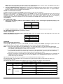
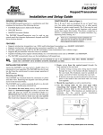
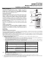
5827 Bidirectional Console
The 5827BD can operate the protection system similarly to other consoles, via its
keypad. In addition, its three LEDs (red, green, and yellow) and piezoelectric
sounder can indicate status information relative to: system arming/ trouble/
emergency, RF transmission/confirmation, and 5827BD programming and power.
The keypad configuration is similar to that of standard consoles. The [4] key,
however, is also the [ON/STAT] (powerup and system status inquiry) key instead
of a “READY” key, as it is on other consoles (see OPERATION). There are three
panic keys: A, B, and C (comparable to other consoles’ panic key pairs of 1/4),
4/#, and 3/# respectively).
The console, if so programmed, also features “Quick Key” operation, which
allows use of the [#] key instead of entry of the security code when performing
functions.
5800TM Transmitter Module
For every installation of one or more 5827BDs, one 5800TM is required. It
complements the 4281 or 5881 RF receiver in that it transmits the information to
be displayed on, or sounded by, the 5827BD. No modification to the control is
necessary. It connects directly to the control’s console connection points, as
described later.
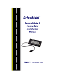
INSTALLATION
ANTENNA
SOUNDER
LEDS
GREEN
YELLOW
RED
C (3/#)
B ( /#)
*
A (1/ )
ARM
SEND/RCV
READY
*
FF
O
AY
AW
AY
ST
UM
IM
AX
M
ST
TE
SS
PA
BY
T
AN
ST
IN
DE
CO
E
IM
CH
PANIC KEYS
4
7
T
TA
N/S
O
POWER-UP KEY
*
2
5
8
0
3
6
9
#
5827BD-001-V0
1
5827BD Bidirectional Console Installation
The console is designed to be portable, for use throughout the protected premises. If desired, it may be stored on its accompanying
mounting bracket (easily installable via two countersunk mounting holes). Keyhole slots on the rear of the console slip onto two hooks
on the mounting bracket, and the console is easily removable.
When operating, or selecting a location for storing the console, observe the same precautions as used for locating the wireless
system’s other transmitters (see the control panel’s instruction manual). For example, operating the console on or near large metal
objects may decrease range and/or block transmissions.
1. Install the console’s battery by sliding off the battery compartment cover on its rear. Observe polarity! Replace the cover.
2. Program the console’s memory as follows:
a. Power up the console by depressing the [4] key. The yellow LED blinks. In case the console was previously programmed, the
b.
c.
system status may also be annunciated (see Power-up and System Status Inquiry on next page).
Enter console programming mode by depressing the [1] and [3] keys (both at the same time) for 3 seconds. Alternate blinking of
the red and green LEDs confirms that the unit is in console programming mode.
Program the desired functions, in the order given in the table that follows. Note that every sequence starts with a [4] and ends
with a [#].
FUNCTION
1.
2.
3.
4.
5.
Enter YOUR System’s 4-Digit Master Code
Enable Quick Key Operation (arm, disarm, and chime)
or
(Arm and chime, but not disarm)
Enter YOUR 5700/5800System’s House ID
(e.g., 06) selected from 01-31
Enter RF System Used:
5700 System (4281 RF receiver)
or
5800 System (5881 RF receiver)
Exit console programming mode.
[4]
[4]
or
[4]
[4]
[ 4]
or
[ 4]
KEY SEQUENCE
[8]
[1]
[4-Digit Master Code]
[4-Digit Master Code]
[#]
[#]
[2]
[9]
[4-Digit Master Code]
[0] [6]
[#]
[#]
[5]
[7]
[#]
[5]
[8]
[#]
[4] [#]
Notes: 1) Upon the detection of each closing ‘#’, a confirmation sound is generated:
x following a valid entry, a triple beep
x following an erroneous entry, a single, long (2 sec) beep.
2) The 5827BD can be reprogrammed at any time.
3) Each time the console-programming mode is entered, Quick Key operation is disabled and must be reenabled, if so desired.
3.
Affix the appropriate panic key label to the space below any panic key that is active, according to the function that has been
programmed for it in the control. A sheet of labels accompanies the 5827BD.
Note: Not all of the three panic keys may be active for the system with which the console is used. This depends on the type of
control used and its programming. Refer to the control’s installation manual.
4. Connect the provided antenna, if necessary, by screwing it into its threaded connector at the top of the console. The 5827 has
an internal antenna, and in many installations the system will operate adequately with this antenna alone. For large installations,
however, it may be necessary to add the external antenna.
5800TM Transmitter Module Installation
Installation instructions accompany the 5800TM, but are given here as well, for your convenience.
Observe the same precautions in selecting a location for the 5800TM as for the system’s 4281 or 5881 RF receiver, to insure good
transmission and reception. The 5800TM must be located next to the system’s receiver (between one and two feet from the
4281/5881’s antennas). Do not install the 5800TM within the system control panel’s cabinet. Mount it remotely, on its accompanying
mounting bracket. The bracket is identical to the one that accompanies the 5827BD and may be mounted the same way.
PROGRAMMING
For an addressable system:
1. Select on e of the following addresses for the 5800tm by removing its cover, and cutting the appropriate jumper(s) on its
circuit board, as follows:
FOR ADDRESS
CUT JUMPER(S)
28
29
30
RED (W1)
WHITE (W2)
BOTH
2. Program the control panel, by assigning the address selected above to one of the wired consoles in the system.
For a Non-Addressable System: No programming is required.
WIRING CONNECTIONS
Connect the 5800TM to the control panel’s connection points, using the supplied connector with flying leads. Wire colors and
functions match those for consoles:
RED
BLACK
GREEN
YELLOW
BLUE
+12VDC
Ground
Data to Control Panel
Data from Control Panel
Not used
OPERATION
Power-up and System Status Inquiry
Touching the [4] ([ON/STAT]) key powers up the 5827BD, and sends an inquiry to the 5800TM, requesting the system status to be
annunciated (see table on next page). Subsequent depressions of the same key will initiate additional inquiries.
Notes: 1. Upon power-up (by depression of the [ON/STAT] key), the yellow LED will blink. The yellow LED will be lit during RF
communication, indicating transmission is in progress or reception has just been completed. If a low battery condition exists
in the 5827BD, it will be displayed on wired consoles as zone 00.
2. At any time (following a power-up), the depression of any key and its acceptance by the console will be indicated by a blink
of the yellow LED, and a brief key actuation ‘blip’ will be heard. (As explained later, a panic key has to be continuously
depressed for at least 2 seconds in order to power-up and/or be accepted by the system).
3. A long (2 second) beep, occurring within 4 seconds after power-up or following the last key depression (of a command or an
inquiry) indicates lack of response from the control (via the 5800TM). Press the [ON/STAT] key again (or move to a new
location and re-key your command).
Approximately 10 seconds after the last key depression, the 5827BD will automatically power down.
No subsequent LED or sound indications will occur until the unit is again powered up (thus, in chime mode, the chime is not
annunciated by the 5827BD).
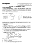
The following table shows the various status indications that can occur during the time that the unit is powered up:
SYSTEM STATUS INDICATIONS for 5827BD
LED
RED
(ARM)
LED
CONDITION
CONSOLE’S SOUNDER
2
ON
STEADILY
2 BEEPS
2
3 BEEPS
3
PULSED BEEPING
BLINKING
STEADY SOUND
3
SILENT
-2-
SYSTEM STATUS
1
ARMED AWAY OR MAXIMUM
ARMED STAY OR INSTANT
ARMED, FIRE ALARM IN PROGRESS, OR MEMORY
OF IT IS PRESENT
ARMED, BURGLARY IN PROGRESS, OR MEMORY
OF IT IS PRESENT
DISARMED, BUT NOT YET CLEARED OF ALARM
MEMORY HISTORY (BURGLARY OR FIRE)
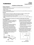
SYSTEM STATUS INDICATIONS for 5827BD (continued)
LED
GREEN
(READY)
4
YELLOW
(SEND/RCV)
LED
CONDITION
ON STEADILY
BLINKING
BLINK
BLINK
CONSOLE’S SOUNDER
SYSTEM STATUS
2
1 BEEP
SILENT
BRIEF “BLIP”
SILENT
1
DISARMED, READY TO ARM
DISARMED, NOT READY TO ARM
KEY DEPRESSION AFTER POWER-UP
UPON 5827BD POWER-UP
RF TRANSMISSION IN PROGRESS OR RECEPTION
JUST COMPLETED
and, as explained in the INSTALLATION section for the 5827BD:
RED &
GREEN
1
2
3
4
ALTERNATELY
BLINKING
SILENT
5827BD IS IN CONSOLE PROGRAMMING MODE
With 4111CM and VISTA 20 systems, status monitoring is restricted to Partition 1; however, each partition can be
controlled by 5827BDs programmed to the partition’s House ID.
Upon the depression of the [ON/STAT] key or following an ARM or DISARM sequence.
May be toggled off/on (any number of times) by means of the [ON/STAT] key. Upon toggling “off,” the armed status
(2 or 3 beeps) is reannunciated. See Alarm Memory on next page.
No yellow light blinking may indicate a low battery (also displayed on wired consoles as “00”).
Routine Operation
The routine operation of the 5827BD (Arm, Disarm, Chime) is
similar to the operation of other consoles used with the system
(as described in the system’s User’s Manual).
Press the [ON/STAT] key before performing the desired
operation.
Note: The following considerations are necessitated by the
fact that there is no zone display on the 5827BD:
a. If the system is “not ready to arm” (green LED blinking),
a conventional console’s display can determine which
zone is “not ready.”
b. Bypassing protection zones should only be performed at
a conventional console so that it can be determined
which zones are to be bypassed.
c. Alarm memory history, if present (see Alarm Memory on
next page), should be cleared only at a conventional
console so that the zone(s) displayed there that were in
alarm condition can first be determined.
Quick Key Operation
If programmed for Quick Key operation, the 5827BD permits
the use of the [#] key (instead of the usual 4-digit security
code) for all functions, or for all functions except disarm, as
selected earlier.
First press the [ON/STAT] key.
Next press the [#] key and the desired function key as follows:
Quick Key Arm:
This is similar to the QUICK ARM function via conventional
consoles, but once programmed here, it is always functional,
whether the system is programmed for QUICK ARM or not.
To Arm AWAY, enter:
[#] + [AWAY]
To Arm STAY, enter:
[#] + [STAY]
To Arm INSTANT, enter:
[#] + [INSTANT]
To Arm MAXIMUM, enter: [#] + [MAXIMUM]
Quick Key Disarm:
This is a unique function. Conventional consoles do not allow
“quick” disarming.
To DISARM, enter:
[#] + [OFF]
Not all of the three panic keys will be active for the system with
which the console is used. This depends on the capabilities of
the control used and its programming.
No prior depression of the [ON/STAT] key is needed.
Depression of any of the 3 panic keys for two seconds causes
the transmission of its function (if/as programmed by the
control) and powers up the console as well. The yellow
transmission/reception LED will light, a brief key actuation
“blip” will occur, and the display of the system status will be
initiated, but (for personal safety purposes) confirmation
sounds will not be emitted.
Alarm Memory
If the [ON/STAT] key is pressed during or following a fire or
burglary alarm-sounding period, the 5827BD console will
annunciate the appropriate warning sounds.
Successive depression of the [ON/STAT] key will toggle these
sounds off and on to alternate with the annunciation of the
system’s armed or disarmed status.
Quick Key Chime
To toggle CHIME mode on or off, enter [#] + [CHIME]
Panic Keys
The ‘A’, ‘B’, and ‘C’ keys (see the diagram) are comparable to
other console key pairs of 1/4), 4/#, and 3/# respectively and
their function will correspond to the control’s programming for
them.
LEDs:
The system can be disarmed by entering the appropriate
disarm sequence at the 5827BD, or any console.
Alarm memory history will still be present, however, as
evidenced by the 5827BD’s blinking red LED, and silent
sounder.
Normally, alarm memory history is cleared by entering the
system’s disarm sequence a second time after the system is
disarmed. In this case, this second disarm sequence should
be performed at a conventional console, after the zone(s)
displayed there that were in alarm condition have been
determined.
5827BD SPECIFICATIONS
Physical: 2-3/8” W x 6-1/4” H x 1-1/4” D
(61mm x 159mm x 32mm)
Battery
Sounder:
-3-
9-volt Alkaline. Ademco 464, Duracell MN1604, or
Eveready 522. (If a low battery condition exists, it
will be displayed on wired consoles as zone 00).
Red, Green, and Yellow, for system status
indications.
Piezoelectric, 4200 Hz, for confirmation, trouble
and emergency beeps and sounding on alarm. In
addition, upon lack of response from the control, a
long (2 second) beep is heard.
REFER TO THE INSTALLATION INSTRUCTIONS FOR THE CONTROL PANEL WITH WHICH THIS DEVICE IS
USED, FOR DETAILS ON LIMITATIONS OF THE ENTIRE ALARM SYSTEM.
FCC ID; CFS8DL5827BD-1
This device complies with Part 15 of the FCC Rules. Operation is subject to the following two conditions: (1) This device may not cause
harmful interference, and (2) this device must accept any interference received, including interference that may cause undesired
operation.
Industry Canada: 1748A5827BD1
FEDERAL COMMUNICATIONS COMMISSION (FCC) STATEMENT
This equipment has been tested to FCC requirements and has been found acceptable for use. The FCC requires the following statement for your
information:
This equipment generates and uses radio frequency energy and if not installed and used properly, that is, in strict accordance with the manufacturer's
instructions, may cause interference to radio and television reception. It has been type tested and found to comply with the limits for a Class B
computing device in accordance with the specifications in Part 15 of FCC Rules, which are designed to provide reasonable protection against such
interference in a residential installation. However, there is no guarantee that interference will not occur in a particular installation. If this equipment does
cause interference to radio or television reception, which can be determined by turning the equipment off and on, the user is encouraged to try to correct
the interference by one or more of the following measures:
•
If using an indoor antenna, have a quality outdoor antenna installed.
•
Reorient the receiving antenna until interference is reduced or eliminated.
•
Move the radio or television receiver away from the receiver/control.
•
Move the antenna leads away from any wire runs to the receiver/control.
•
Plug the receiver/control into a different outlet so that it and the radio or television receiver are on different branch circuits.
If necessary, the user should consult the dealer or an experienced radio/television technician for additional suggestions. The user or installer may find
the following booklet prepared by the Federal Communications Commission helpful:
"Interference Handbook"
This booklet is available under Stock No. 004-000-00450-7 from the U.S. Government Printing Office, Washington, DC 20402.
The user shall not make any changes or modifications to the equipment unless authorized by the Installation Instructions or User's Manual.
Unauthorized changes or modifications could void the user's authority to operate the equipment.
LIMITED WARRANTY
Honeywell International Inc., acting through its Security & Custom Electronics business ("Seller") 165 Eileen Way, Syosset, New York 11791, warrants
its product(s) to be in conformance with its own plans and specifications and to be free from defects in materials and workmanship under normal use and
service for 24 months from the date stamp control on the product(s) or, for product(s) not having a manufacturer’s date stamp, for 12 months from date
of original purchase unless the installation instructions or catalog sets forth a shorter period, in which case the shorter period shall apply. Seller's
obligation shall be limited to repairing or replacing, at its option, free of charge for materials or labor, any product(s) which is proved not in compliance
with Seller's specifications or proves defective in materials or workmanship under normal use and service. Seller shall have no obligation under this
Limited Warranty or otherwise if the product(s) is altered or improperly repaired or serviced by anyone other than Honeywell factory service. For
warranty service, return product(s) transportation prepaid, to Honeywell Factory Service, 165 Eileen Way, Syosset, New York 11791.THERE ARE NO
WARRANTIES, EXPRESS OR IMPLIED, OF MERCHANTABILITY, OR FITNESS FOR A PARTICULAR PURPOSE OR OTHERWISE, WHICH
EXTEND BEYOND THE DESCRIPTION ON THE FACE HEREOF. IN NO CASE SHALL SELLER BE LIABLE TO ANYONE FOR ANY
CONSEQUENTIAL OR INCIDENTAL DAMAGES FOR BREACH OF THIS OR ANY OTHER WARRANTY, EXPRESS OR IMPLIED, OR UPON ANY
OTHER BASIS OF LIABILITY WHATSOEVER, EVEN IF THE LOSS OR DAMAGE IS CAUSED BY THE SELLER'S OWN NEGLIGENCE OR FAULT.
Seller does not represent that the product(s) it sells may not be compromised or circumvented; that the product(s) will prevent any personal injury or
property loss by burglary, robbery, fire or otherwise; or that the product(s) will in all cases provide adequate warning or protection. Customer
understands that a properly installed and maintained alarm system may only reduce the risk of a burglary, robbery, fire, or other events occurring without
providing an alarm, but it is not insurance or a guarantee that such will not occur or that there will be no personal injury or property loss as a result.
CONSEQUENTLY, SELLER SHALL HAVE NO LIABILITY FOR ANY PERSONAL INJURY, PROPERTY DAMAGE OR OTHER LOSS BASED ON A
CLAIM THAT THE PRODUCT(S) FAILED TO GIVE WARNING. HOWEVER, IF SELLER IS HELD LIABLE, WHETHER DIRECTLY OR INDIRECTLY,
FOR ANY LOSS OR DAMAGE ARISING UNDER THIS LIMITED WARRANTY OR OTHERWISE, REGARDLESS OF CAUSE OR ORIGIN, SELLER'S
MAXIMUM LIABILITY SHALL NOT IN ANY CASE EXCEED THE PURCHASE PRICE OF THE PRODUCT(S), WHICH SHALL BE THE COMPLETE
AND EXCLUSIVE REMEDY AGAINST SELLER.
This warranty replaces any previous warranties and is the only warranty made by Seller on this product(s). No increase or alteration, written or verbal, of
the obligations of this Limited Warranty is authorized.
165 Eileen Way, Syosset, New York 11791
Copyright © 2004 Honeywell International Inc.
www.honeywell.com/security
¬19]l
N6484V4 02/04 Rev. A