1
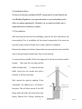
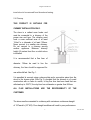
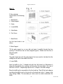
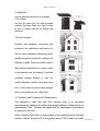
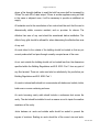
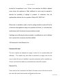
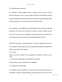
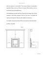
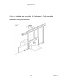
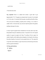
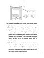
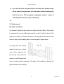
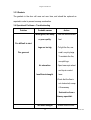
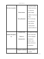
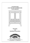
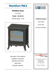
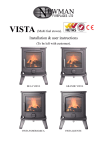
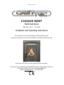
Cougar Inset Manual COUGAR INSET Multi-fuel stove Ref. No. I14 v 1 (11.4.15) Installation and Operating Instructions The Cougar Inset stove must be installed by a suitably qualified engineer. Instructions must be given to the user when installation is complete and the installer must instruct user of the correct use of the appliance and control operation. The Cougar Inset is manufactured to EN13229:2006 for Arbeia Trading Limited, a Division of: Cast Tec Ltd. East Side, Tyne Dock, South Shields NE33 5SP Website: www.casttec.co.uk Tel. 0191 4974299 Cougar Inset Manual Contents Installation Essentials………………………………………………........................3 Pre-installation checks……………………………………………………………….4 Installation introduction with technical data……………………………………..4 1. Technical data………………………………………………………………………4 2. Installation introduction…………………………………………………………..5 2.1 Unpacking the stove……………………………………………………………………………...5 2.2 Installing the stove………………………………………………………………………………...6 2.3. Pre-Installation Assembly………………………………………………………………………..6 2.4. Chimney…………………………………………………………………………………………...7 2.5. Fitting Instructions………………………………………………………………………………...8 2.6. Down Draughts…………………………………………………………………………………..11 2.7. Ventilation & Combustion Air Requirements………………………………………………….11 2.8. Permanent Air Vent Extractor Fan…………………………………………………………….13 2.9. Commissioning & Handover……………………………………………………………………14 2.10. Location…………………………………………………………………………………………14 2.11. Clearance to Combustibles…………………………………………………………………...14 2.12. Floor Protection ……………………………………………………………………………..16 3. User Manual…………………………………………………………………………17 3.1 Choice of fuel……………………………………………………………………………………..17 3.2 Use………………………………………………………………………………………………...18 3.2.1 Use with wood………………………………………………………………………………19 3.2.2 Use with solid fuel…………………………………………………………………………..21 3.2.3 Ash Removal………………………………………………………………………………..24 3.3 Maintenance……………………………………………………………………………………...25 3.3.1 Cleaning glass……………………………………………………………………………...25 3.3.2 External surface cleaning…………………………………………………………………25 3.3.3 Gaskets……………………………………………………………………………………..26 3.4 Operational problems – troubleshooting……………………………………………………....26 2 Cast Tec Ltd Cougar Inset Manual Installation Essentials The installation of a fireplace or stove must be in accordance with local codes and regulations in each country and other national and European standards that apply. Your Cougar Inset stove must be installed by a Competent Person registered with a Government Approved Competent Person’s Scheme. In the UK, Hetas is a qualified body that can assist with general advise, regulation, installation, type of fuel usage and can provide a list of registered Competent Persons: Website is www.hetas.co.uk 3 Cast Tec Ltd Cougar Inset Manual Pre-installation Checks Installation of a fireplace must be according to local codes and regulations in each country. All local regulations, including those which refer to national and European standards, must be observed when installing the product. Both an installation manual with technical data and a manual on general use and maintenance are enclosed with the product. The installation can only be used after it has been inspected by a qualified inspector. A name plate of heat-resistant material is affixed to the product. This contains information about identification and documentation for the product. Installation Introduction with Technical Data 1. Technical data Material: Cast iron Finish: High-temp. resistance paint Fuel: Multi-fuel Log length, max.: 30CM Operating range: 2.0—5.0kW Flue outlet: Top or Rear Flue pipe dimension: - Inside: 125 mm/124 cm2 cross section Approx. weight: 74.5kgs 4 Cast Tec Ltd Cougar Inset Manual Dimensions, distances etc.: figure 2 Technical data according to EN 13229:2006 Nominal heat output (Max): 5KW Flue gas mass flow: 5.0 g/sec Recommended chimney draught: 12 Pa Efficiency: 76%@5kW CO emission (13% O2): 0.53% Flue gas temperature: 3850C Operational mode: Intermittent Intermittent combustion in this context means normal use of the fireplace, i.e. fuel is added as soon as the fuel has burnt down to on all our products there is a label a suitable amount of embers. 2. Installation 2.1 Unpacking the Stove After removing the outer packaging, unbolt the combustion chamber from the wooden pallet and place it gently on its back. The cardboard packaging can be placed underneath to prevent marring. Remove the leg pack from the stove and bolt each leg securely to the underside of the base on the combustion chamber, using the bolts provided (found inside the stove). We recommend that two people perform the assembly and installation procedure. 5 Cast Tec Ltd Cougar Inset Manual 2.2 Installing this Stove The stove and chimney installations MUST comply with all current National and Local Building Regulations; your approved dealer or your local building control officer can advise regarding this. Ultimately, it is you and your installer who is responsible that the installation complies. 2.3 Pre-installation After removing the stove from the packaging, open the fire door and remove the loose packing. Prior to installation all the internal components of the stove are removed to gain access to fixings and to make it lighter for installation. Remove the refractory fire bricks, these bricks are loose and just need to be lifted clear of the grate support plate before they can be removed. To remove the loose baffle, lift the front edge until it hits the top and then slide it forward. Then drop the rear edge and the baffle will slide down. To remove the fixed baffle, loosen the two screws and slide it forwards, it will then drop down. Next, remove the grate by pushing it from underneath, the riddling bar is not fixed to the grate. This will allow access to four M6 fixings which will attach the stove to the outer casing. Remove the 4 fixings, allowing the 6 Cast Tec Ltd Cougar Inset Manual insert stove to be removed from the external casing. 2.4 Chimney THIS PRODUCT IS SUITABLE FOR CHIMNEY INSTALLATION ONLY. The stove is a radiant room heater and must be connected to a chimney of the proper size and type. The chimney must have a cross sectional area of at least 124cm2 or a diameter of at least 125mm. Never connect to a smaller size chimney. Do not connect to a chimney serving another appliance. Minimum chimney height 4.5 meters from floor on which stove is installed. It is recommended that a flue liner of diameter 125mm be used to line the chimney, the liner should be approved for use with solid fuel. See Fig. 1. It is permitted to connect using a closure plate and a connection piece from the stove to the closure plate (See Fig 2), provided that the chimney is of sound construction with no leaks or cracks, a clay flue liner has been used that can o withstand up to 1000 C, the clay liner has a diameter no greater than 200mm. ALL FLUE INSTALLATIONS ARE THE RESPONSIBILITY OF THE CUSTOMER. The stove must be connected to a chimney with a minimum continuous draught of 12 Pascal’s (.05” WG). Poor draught conditions will result in poor performance. 7 Cast Tec Ltd Cougar Inset Manual FITTING INSTRUCTIONS Step 1 Prepare the fireplace area with fireback or milner brick removal. Ensure the opening is suitable for fitting of the insert stove opening required, i.e. remove fire surround trim if fitted. See Fig 3 Step 2 Ensure the floor area is level with the hearth, this area needs to be level as the insert fire is screw fixed to the floor. Step 3 Lay the external casing into the opening and position so that the front edge protrudes 20mm past the front edge of the opening. Step 4 Mark the drill location and drill the holes using a 4.5mm drill bit. Fix the casing to the floor using the self tapping screws provided. 8 Cast Tec Ltd Cougar Inset Manual Step 5 Lift the stove into the external casing. Remove all internal parts as per pre-assembly instructions prior to lifting it. The stove can be lifted into the casing approximately 125mm first and then it can be pushed into the final position while taking care to lift the front edge to preserve the hearth. Step 6 Drop the flexi flue liner down through the chimney and into the stove. Step 7 Lay the sealing gasket on to the flue spigot, and then fit the flue spigot to the end of the flexi flue liner using the 2 grub screws provided. Step 8 Then using the M6 screws secure the stove to the convection chamber. Push the insert stove against the fireplace before fully tightening these bolts. Step 9 Push the flexi liner back up through the flue outlet and fix the flue spigot into position using the M6 nuts provided. It may be necessary to cut a prop to hold the spigot in place while the fixings are being attached. Step 10 Complete the installation of the flexi line at the top of the chimney in accordance with the manufacturer’s instructions. 9 Cast Tec Ltd Cougar Inset Manual Step 11 Fit the individual components in the following order: 1. Back Bricks 2. Grate Support 3. Grate 4. Loose Baffle 5. Side Bricks 6. Fire Fence 1. Back Bricks Lay the back bricks in as shown. 2. Grate Support Tilt the grate support up on one side and pass it carefully through the door opening, it should then rest on three supports approx. 100mm from the floor of the stove grate. 3. Grate The grate simply lays into the grate support but care needs to be taken that the riddling bar will rest in the middle of the fork. 4. Loose Baffle Hold the baffle by the ‘L’ shaped end with the fold turned up. Manoeuvre it diagonally through the door opening and then drop the rear edge to the rear of the stove. Lift the ‘L’ shaped edge up over the ‘L’ shape on the side castings. Move the baffle as far as possible to the front and top. Then lift the back edge up and allow the baffle to rest on the top rib on the back and in the ‘L’ shape on the side castings. Note: The secondary air holes must be visible underneath the baffle. 10 Cast Tec Ltd Cougar Inset Manual 5. Side Bricks Lay the side and back bricks in as shown. 6. Fire Fence Lay the fire fence into the slots provided ensuring that they slope from front to back so that no embers can fall out through the fire fence. 2.6 Down Draughts However well designed constructed and positioned, the satisfactory performance of the flue can be adversely affected by down draught caused by nearby hills, adjacent tall buildings or trees. These can deflect wind to blow directly down the flue or create a zone of low pressure over the terminal. A suitable anti-down draught terminal or cowl will usually effectively combat direct down blow but no cowl is likely to prevent down draught due to a low pressure zone. (See Fig.5) 2.7 Ventilation and Combustion Air Requirements This appliance is rated less than 5kW, therefore there is no mandatory requirements for additional air unless a flue draught stabiliser is fitted then the air 2 requirement is 15cm . However, we suggest that it is advantageous to provide an air supply into the room. When calculating combustion air requirements for this appliance use the following 2 equation: 550mm per each kW of rated output above 5 kW should be provided, 11 Cast Tec Ltd Cougar Inset Manual where a flue draught stabiliser is used the total free area shall be increased by 2 300mm for each kW of rated output. If there is another appliance using air fitted in the same or adjacent room, it will be necessary to provide an additional air supply. All materials used in the manufacture of air vents should be such that the vent is dimensionally stable, corrosion resistant, and no provision for closure. The effective free area of any vent should be ascertained before installation. The effect of any grills should be allowed for when determining the effective free area of any vent. Air vents direct to the outside of the building should be located so that any air current produced will not pass through normally occupied areas of the room. An air vent outside the building should not be located less than the dimensions specified within the Building Regulations and B.S. 8303: Part 1 from any part of any flue terminal. These air vents must also be satisfactorily fire proofed as per Building Regulations and B.S. 8303: Part 1. Air vents in internal walls should not communicate with bedrooms, bedsits, toilets, bathrooms or rooms containing a shower. Air vents traversing cavity walls should include a continuous duct across the cavity. The duct should be installed in such a manner as not to impair the weather resistance of the cavity. Joints between air vents and outside walls should be sealed to prevent the ingress of moisture. Existing air vents should be of the correct size and unob 12 Cast Tec Ltd Cougar Inset Manual structed for the appliance in use. If there is an extraction fan fitted in adjacent rooms where this appliance is fitted, additional air vents may be required to alleviate the possibility of spillage of products of combustion from the appliance/flue while the fan is in operation. Refer to B.S. 8303 Part 1. Where such an installation exists, a test for spillage should be made with the fan or fans and other appliances using air in operation at full rate, (i.e. extraction fans, tumble dryers) with all external doors and windows closed. If spillage occurs following the above operation, an additional air vent of sufficient size to prevent this occurrence should be installed. 2.8 Permanent Air Vent Extractor Fan Permanent Air Vent The stove requires an adequate air supply in order for it to operate safely and efficiently. The installer may have fitted a permanent air supply vent into the room in which the stove is installed to provide combustion and/or ventilation air. This air vent should not under any circumstances be shut off or sealed. Extractor Fan There must not be an extractor fan fitted in the same room as the stove as this can cause the stove to emit smoke and fumes into the room. 13 Cast Tec Ltd Cougar Inset Manual 2.9 Commissioning & Handover On completion of the installation allow a suitable period of time for any fire cement and mortar to dry out, when a small fire may be lit and checked to ensure the smoke and fumes are taken from the stove up the chimney and emitted safely to the atmosphere. Do not run at full output for at least 24 hours. On completion of the installation and commissioning ensure that the operating instructions for the stove are left with the customer. Ensure to advise the customer on the correct use of the appliance with the fuels likely to be used on the stove and warn them to use only the recommended fuels for the stove. Advise the user what to do should smoke or fumes be emitted from the stove. The customer should be warned to use a fire guard to BS 6539 in the presence of children, aged and/or infirm persons 2.10 Location There are several conditions to be considered in selecting a location for your stove. A. This product is designed to be installed into a fire place. B. Allowances for proper clearances to combustibles. 2.11 Clearance to Combustibles This appliance must be installed in a recess, the recess should not contain any combustible materials. Wooden battens and plaster board should not be used 14 Cast Tec Ltd Cougar Inset Manual within the clearance to combustibles. The minimum clearance to combustibles required is 600mm to the top, 350mm to the sides, 550mm directly to the front and 350mm to any combustible flooring. If the mantelpiece protrudes further than 100mm from the fireplace, then it will be necessary to have further clearance to the top of the stove. The distance the mantle protrudes past the 100mm should be added to the clearance. For example, if the mantle protrudes 200mm, the clearance to the mantle should be 650mm. (See-Fig6). Fig. 6 15 Cast Tec Ltd Cougar Inset Manual If there is a studded wall surrounding the fireplace as in Fig.6, ensure the clearances in this Fig7 are adhered to. 16 Cast Tec Ltd Cougar Inset Manual 2.12 Floor Protection It is recommended that this appliance is installed on a solid, level, concrete base, a non combustible hearth conforming to current Building Regulations must extend to the front of the appliance. 3.0 User Manual 3.1 Choice of Fuel Recommended fuel: Wood - Use hard wood logs. Although you can fire this product with almost all kinds of wood, you should not fire with wet wood, or unseasoned wood. Wood ought to be stored under a roof for at least 1 year, and preferably 2 years, with free access to wind. Wood should be chopped as soon as possible after felling if it is to dry quickly. The wood can be used once the moisture content is less than 20%. During the EN test, all stoves are tested with wood with a moisture content of (16 ± 4)%. - Hardwood has a higher calorific value as the same volume (oak, ash, maple, birch, elm, beech, etc.). 17 Cast Tec Ltd Cougar Inset Manual -Pieces of wood with a diameter greater than 10 cm should always be chopped. The pieces of wood should be short enough to be able to lie flat over the layer of embers, with air at both ends. The maximum length of fuel in the stove is no more than 30cm. Recommended fuel: Coal Smokeless fuels, including coalite nuts, phurnacite, ancit and extracite. Not recommended as fuel :“Green wood”. Green or damp wood reduces stove efficiency and soils the glass, the internal walls and the flue (soot, tar, etc.). - “used timbers”. Burning treated wood (railway sleepers, telegraph poles, offcuts of plywood or chip board, pallets, etc.) quickly clogs the flue ways (soot, tar, etc.), pollutes the environment (pollution and smell, etc.) and cause the fire to burn too quickly and overheat. “Green wood” and “recovered wood” can eventually cause a chimney fire. Prohibited fuel: plastic bags and any form of bituminous coal or petroleum based coke. This may harm the product and pollute the atmosphere. 3.2 Use 18 Cast Tec Ltd Cougar Inset Manual Odours when using the fireplace for the first time Painted products: the fireplace may emit an irritating gas when used for the first time, and it may smell a little. The gas is not toxic, but the room should be thoroughly ventilated. Let the fire burn with a high draught until all traces of the gas have disappeared and no smoke or smells can be detected. Enameled products: Condensation may form on the surface of the fireplace the first few times it is used. This must be wiped off to prevent permanent stains forming when the surface heats up. Air Control: Figure 8 The amount of heat emitted by the stove is regulated using two air controls. The primary air supply, where air passes up through the riddling grate, is controlled using the lower air control and the secondary air (airwash system), which is supplied to the combustion over the glass, is controlled using the upper air control. 3.2.1 Use with Wood l Lighting Figure 8 • Slide the top air control to open. Open the lower control. 19 Cast Tec Ltd Cougar Inset Manual • Lay firelighters or rolled up newspapers on the grate with a reasonable quantity, if necessary, of dry kindling wood. Place 2 or 3 small logs on top. • Light the newspaper or firelighters using a long taper and close the door. • When the fire is burning fiercely, add further logs of a diameter up to 10 cms. • When the stove body is very hot, close the lower control. • The burning rate can now be lowered by moving the top air control to smaller air inlet. l Re-fuelling Figure 8 • Slide the top air control to open. Open the lower control. • Open the glass door and add logs. (To load fuel, the door should be opened slowly, avoiding a sudden rush of intake air, so that smoke does not escape into the room.) • Leave the lower control open for a few minutes to allow the initial volatiles in the 20 Cast Tec Ltd Cougar Inset Manual wood to burn. • Close the lower control. Very Important: Wood is a material that contains a great deal of gas (approximately 75 %). The gases are released when the wood is lit and heated up. For this reason, it is important that the gases are ignited quickly after stoking. If the wood just lies smoldering, especially after re-stoking, a lot of smoke is created, which, in the worst case, may cause an explosive ignition of the gasses, resulting in damage to the stove. In order to ignite the gases that are released from the wood, and to keep clear, lasting flames during the combustion process, it is important to let in the required quantity of oxygen (air supply) at all times. The setting of the air supply, the method of ignition and the lighting intervals depend on the draught in the chimney, the wind and weather, the amount of heat required the fuel, etc. This means that it may take some time before you get to know the correct functioning of the stove under any given circumstances. 3.2.2 Use with Solid Fuel l Lighting Figure 8 21 Cast Tec Ltd Cougar Inset Manual • Slide the top air control to open. Open the lower control. • Lay firelighters or rolled up newspapers on the grate with a reasonable quantity, if necessary, of dry kindling wood. Place a small quantity of solid fuel on top. • Light the newspaper or firelighters using a long taper and close the door. • When the fire is burning fiercely, add further fuel. • When the stove body is hot, close the top air control. • The burning rate can now be adjusted by the lower control. l Re-fuelling Figure 8 • Open the lower control. • Open the glass door and add fuel. (To load fuel, the door should be opened slowly, avoiding a sudden rush of intake air, so that smoke does not escape into the room.). • Leave the lower control open for a few minutes to allow the initial volatiles in the fuel to burn. • Adjust the lower control to the desired positio 22 Cast Tec Ltd Cougar Inset Manual Very Important: The stove door should never be opened when the stove is being fired vigorously. l We would strongly recommend that you do not leave your stove alit at night. It harms the environment, and constitutes very poor use of the wood, as the gases in the wood do not ignite at the low temperature, but settle as soot (unburned gases) in the chimney and stove. Extreme conditions, such as poor draught in the chimney, large quantities of wood or wet wood, may, in the worst-case scenario, cause an explosive ignition. l When firing in the summer period, when there is minimal need for heat, the combustion will be poor. The stove provides too much heat, so the combustion should be reduced. But always remember to make sure that there are lasting flames until the wood becomes charcoal. If you want a weaker fire, stoke up using less wood. 23 Cast Tec Ltd Cougar Inset Manual l If you fire the stove using wet wood, a lot of the fuel’s thermal energy will be spent forcing the water out of the wood, without releasing any heat to the stove. This incomplete combustion results in a layer of soot being left in the stove, pipe and chimney. l 3.2.3 Ash removal Fig. 9 (Use of ashpan) It is essential to keep the grate free from a heavy build up of ashes. This product is equipped with a grate riddling device which is used to “shake” ashes off the grate into the ash pan. Whenever the stove is burning without life when the lower control is open, use the riddling lever to clear the grate of surplus ashes. If burning solid fuel, always empty the ash pan at least once a day or whenever it is full of ashes. Never allow the ashpan to overfill allowing ash to be in contact with the underside of the grate. If this condition is allowed, the grate will wear out pre-maturely. 24 Cast Tec Ltd Cougar Inset Manual 3.3 Maintenance 3.3.1 Cleaning Glass This product is equipped with an air wash for the glass. Air is sucked in through the air vent above the fireplace and down along the inside of the glass. However, some soot will always stick to the glass, but the quantity will depend on the local draught conditions and adjustment of the air wash vent. Most of the soot layer will normally be burned off when the air wash vent is opened all the way and a fire is burning briskly in the fireplace. Good advice! For normal cleaning, moisten a paper towel with warm water and add some ash from the burn chamber. Rub it over the glass and then clean the glass with clean water. Dry well and if it is necessary to clean the glass more thoroughly we recommend using a glass cleaner (follow the instructions on the bottle). 3.3.2 External Surface Cleaning The cast surface of the stove is painted with heat-resistant paint. It is best maintained by simply vacuuming it with a soft brush attachment or wiping it down with a dry, dust-free cloth. If the stove is used too vigorously, the painted surface may assume a greyish tinge over time, but the stove can easily be freshened up with spray paint, which is available from your local retailer. 25 Cast Tec Ltd Cougar Inset Manual 3.3.3 Gaskets The gaskets in the door will wear out over time, and should be replaced as required in order to prevent runaway combustion. 3.4 Operational Problems – Troubleshooting Problem Probable causes -Action Wood green, too damp − Use the recommended or poor quality. fuel. Fire difficult to start Logs are too big. Fire goes out − To light the fire, use small, very dry twigs. To maintain the fire, use split logs. Air starvation. − Open lower spin wheel and top air control Insufficient draught. lever. −Check that the flue is not obstructed, sweep it if necessary Seek advice from a chimney specialist. Too much draught. 26 − Ensure that the lower Cast Tec Ltd Cougar Inset Manual spin wheel is closed Fire burns too quickly. Partially close the top air control lever. Excessive draw. − Install a draught stabiliser. Consult your Dealer. Poor quality wood. − Do not continuously burn small wood, sticks, bundles, carpentry offcuts (plywood, pallets), etc. Flue duct is cold. Smokes when lighting up. − Burn paper and kindling wood to increase heat. Room is in decompression. − In houses equipped with mechanical ventilation, open a window until the fire is well established. . Draught is insufficient − Consult a chimney specialist. 27 Cast Tec Ltd Cougar Inset Manual Check that the flue is Smokes while burning. not obstructed, sweep if necessary. Down draught. − Install an anti-down draught cowl. Consult your Dealer. Room is in − In houses equipped decompression. with Mechanical Ventilation, an outside air intake must be installed for the chimney. Low heat output. Incorrect Fuels. − Use the recommended fuel. 28 Cast Tec Ltd