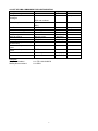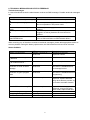
1
USER MANUAL
Mobeye® Panic Button
CM2500
SW version 1.n
Attention! Very important
This user manual contains important guidelines for the installation and usage of the Mobeye® device as
described in this manual. Please read these thoroughly before you start using the Mobeye® device!
In case of damage caused by disregarding the guidelines, the warranty expires.
The user must regularly check the proper functioning of the device. The manufacturer cannot be held
liable for any damage caused by any incorrect use or incorrect functioning of the Mobeye® device.
Safety guidelines
• The permitted ambient temperature during operation may not be exceeded (not lower than -10°C and
not higher than 50°C).
• The device is intended for use in dry and clean places.
• Protect the device from moisture, heat and water splashing.
• The guidelines for the battery usage must be regarded.
• Do not expose the device to strong vibrations.
• Do not let it fall from height.
• Do not use in an environment where any inflammable gases, vapors or dust are present or could be
present.
• The repairs of the device may only be carried out by people, trained for Mobeye® repair.
• In case the device must be repaired, only original replacement components may be used. The use of
different parts may lead to damage of the Mobeye® device.
Use in accordance with the regulation
The use of this device in accordance with the regulation is sending SMS text messages and making
telephone calls after an alarm situation. Other usages are not permitted.
Battery recycling
CR123 batteries, as used in the Mobeye Panic Button, are classified as non-hazardous waste and can
be recycled. Please take empty batteries to a nearest collection point.
CONTENT
1.
2.
General description
Getting started
2.1
Place a SIM card
2.2
Place the batteries
2.3
Enter the program mode
2.4
Program at least one telephone number
3.
External emergency button and power supply
3.1
Using an external emergency button
3.2
Using external power
4.
Extended options
4.1
Program mode
4.2
The security code
4.3
Programming the settings by SMS
4.4
Possible General settings
4.4.1 Phone numbers
4.4.2 Identification text
4.4.3 Alarm text
4.4.4 Alarm notification type: SMS or SMS + call
4.4.5 Input delay time
4.4.6 Alarm repeat time
4.4.7 Test SMS text message
4.4.8 Power failure SMS message
4.5
Reset of system
4.6
List of SMS commands for configuration
5.
Request overview of the settings and status
5.1
Status request
5.2
Overview general settings
5.3
Overview phone numbers
6.
Technical messages and status feedback
1
2
2
2
2
2
3
3
3
4
4
4
4
5
5
5
5
5
6
6
6
6
6
7
8
8
8
8
9
1. GENERAL DESCRIPTION
The Mobeye Panic Button is a battery operated GSM module used to send out an alarm after a
triggered input or - if external power supply is used- after a power failure.
The Mobeye Panic Button is pre-programmed with standard action-reaction patterns. To change this
behaviour please refer to chapter 4.
The factory settings of the Mobeye Panic Button cause following reactions:
- In case of a panic alarm, the Mobeye Panic Button sends an alarm SMS text message and calls to the
phone numbers as programmed. The SMS message contains the text ‘Mobeye Panic alarm’,
- In case external emergency buttons are connected to the external inputs and these are activated, the
Mobeye Panic Button sends an alarm SMS text message and calls to the phone numbers as
programmed. The SMS message contains the text ‘Mobeye Panic alarm’.
- In case the batteries need to be replaced, the Mobeye Panic Button sends a ‘battery low’ SMS text
message to the administrator.
- In case an external power supply is used and a power failure occurs, the Mobeye Panic Button sends
a ‘power failure’ SMS text message to the administrator. In case the power is restored, the Mobeye
Panic Button sends a ‘power restored’ SMS text message to the administrator.
1
2. GETTING STARTED
To get started with the Mobeye Panic Button at least the following steps need to be taken in following
order:
1.
2.
3.
4.
Place SIM card (with PIN code 0000 or without PIN code)
Place the batteries
Enter the program mode
Program at least one telephone number (administrators’ number)
These steps are further explained in this chapter. After these steps the module will be operational.
2.1 PLACE A SIM CARD
Open the enclosure with the 4 screws and insert a SIM card into the module. Push the black cover
outward slightly to open the holder. Before installing the SIM card should have PIN code "0000", or be
free of a PIN code.
(A PIN code can be changed or removed by putting the SIM card in a mobile phone and change or remove the
PIN in the security menu.)
NB: make sure the SIM card is inserted before the batteries are placed. In case of a SIM card change,
please first remove the batteries (and remove any other external power supply).
2.2 PLACE THE BATTERIES
Place the two batteries (CR123) in the module. Use the +/- indication for the correct placement. The
green LED will flash to indicate that the module is not configured (at least one telephone number should
be programmed).
2.3 ENTER THE PROGRAM MODE
Directly after placing the batteries, the Mobeye Panic Button switches to the program mode. First the
GSM module establishes network connection. During this time the LED flashes 2 sec. on/1 sec. off.
Within 10-30 seconds the connection is established and the status LED starts flashing 1 sec. on/1 sec.
off (or ‘on’ in case the first telephone number has been configured).
During the first 3 minutes, the GSM module remains open, ready to receive SMS commands. After 3
minutes a time-out occurs and the GSM module switches off in order to save the batteries. The unit
returns to the low power operational mode. To return to the program mode, re-enter the batteries.
2.4 PROGRAM AT LEAST ONE TELEPHONE NUMBER
The Mobeye Panic Button is able to send messages up to 5 telephone numbers. The first telephone
number belongs to the administrator. Technical messages (like “battery low”) are sent to the
administrator only. Without the administrators’ phone number, the Mobeye Panic Button cannot not
function.
When the Panic Button is in initial (factory) status and the batteries are placed (so the LED is flashing),
the administrators’ number is programmed by calling the telephone number of the Mobeye Panic Button
using the administrators’ phone. The unit will recognize this number and store it as administrator
(telephone number 1). The administrator will receive a confirmation SMS text message including the
security code. This code is needed to program the other settings in the unit.
NB: for this way of programming the number recognition in the administrator’s phone must be ‘on’. To
program or change the administrators’ number by SMS command, please refer to 4.4.1.
After the previous steps, the Mobeye Panic Button is ready for use. The green LED blinks once in 3
seconds.
NB : the Mobeye Panic Button is developed to run on batteries. As soon as the button is pressed during
1 second or longer, the module establishes GSM network connection. This could take approximately
15-20 seconds, depending on the local network strength. In order to shorten this time, the Mobeye
Panic Button could be powered externally. The integrated GSM module will always be open and having
network connection. The panic alarm will reach the contact persons faster.
2
3. EXTERNAL EMERGENCY BUTTON AND POWER SUPPLY
3.1 USING AN EXTERNAL EMERGENCY BUTTON
It is possible to connect external emergency buttons to the inputs. As soon as the button is pressed
during at least one second, the Mobeye Panic Button reacts similar as after pressing the on/off button; it
sends an SMS text message to the preset numbers and calls these
numbers.
Insert the 2 wires of an external button through the hole of the enclosure to
the inside part and next in the two connectors of input 1 (press on the green
pins for connecting the wires). It does not matter which wire is connected to
which connector. If necessary the wires can be extended up to 5 meters
using appropriate wire material.
For a second external emergency button, use input 2. The inputs are
Normally Open (NO) contacts. The inputs are triggered in case the buttons
are pressed during at least 1 second. In case a button should be activated
shorter or longer before evoking an alarm, please refer to 4.4.5.
1 2
3.2 USING EXTERNAL POWER
Although the Mobeye Panic Button is designed to run on batteries, it is possible to use an external
power supply. In this mode the module is always in connection with the GSM network and therefore
always in program mode. In case the power fails, the batteries take over the functioning and the
administrator is informed by an SMS text message. The module continues operating albeit in the low
power mode. This means the GSM module switches off and only establishes network connection in
case it needs to send out an alarm, test message or battery low alert.
Connect the external power adapter (or any other regulated 12VDC power
supply) to the power input of the connector (press on the green pins for
connecting the wires):
- V+ (black lead with white stripe) to “+”
- Ground (black lead) to “-“
+ -
3
4. EXTENDED OPTIONS
To program the Mobeye Panic Button, the GSM module must have network connection. In case only
batteries are used, first switch the unit to the program mode. Next send SMS commands for the
configuration.
All settings are stored and will be kept in the unit, even in case the power supplies are removed.
4.1 PROGRAM MODE
Directly after placing the batteries, the Mobeye Panic Button switches to the program mode. First the
GSM module establishes network connection. During this time the LED flashes 2 sec. on/1 sec. off.
Within 10-30 seconds the connection is established and the status LED starts flashing 1 sec. on/1 sec.
off (or ‘on’ in case the first telephone number has been configured).
The Mobeye Panic Button returns to the program mode by re-entering the batteries.
As long as the unit is in the program mode, the status LED is on (or flashing 1 sec. on/1 sec. off in case
the module has no configuration). During the first 3 minutes the GSM module remains open, ready to
receive SMS commands. After 3 minutes a time-out occurs and the GSM module switches off in order
to save the batteries. The unit returns to the low power operational mode. In case the unit is connected
to an external power supply, the Panic Button has network connection all the time and the unit is in
program mode all the time.
4.2 THE SECURITY CODE
For configuration activities the security code of the Mobeye Panic Button must be used. The initial
security code is ‘1111’.
In this manual this code is referred to as <CODE>.
4.3 PROGRAMMING THE SETTINGS BY SMS
The settings are programmed by SMS text messages.
- Be sure the Panic Button is in program mode (please refer to 4.1).
- Send an SMS message with following content:
<CODE> <command>
- Do not forget the space character between <PIN code> and <command>.
- The commands are case sensitive.
- Several commands may be combined in one SMS message (with a maximum of 160 characters) by
placing a # between the commands.
<CODE> <command1>#<command2> ...... #<commandN>
The green LED blinks 3 times to indicate the successful configuration. In case of an incorrect
command, the LED flashes 5 times.
In 4.6 the complete scheme with SMS commands is listed
4
4.4 POSSIBLE GENERAL SETTINGS
This paragraph describes the general settings for the Panic Button.
4.4.1 Phone numbers
The Mobeye Panic Button is able to send alarm messages up to 5 phone numbers. The first telephone
number (TEL1) belongs to the administrator. Only this number receives all system messages. The other
phone numbers (including the administrator) only get the alarm messages.
To set or change telephone numbers:
SMS command 1st telephone number:
SMS command 2nd telephone number:
.... similar for TEL3...TEL5
<CODE> TEL1:<tel. number>
<CODE> TEL2:<tel. number>
To delete telephone numbers:
SMS command delete 1st telephone number: <CODE> DEL1
.... similar for DEL2...DEL5
In case a foreign number needs to be entered start with 00 follow by the country code (e.g.
0031612345678).
4.4.2 Identification text
It is possible to add a standard identification text (NAME) to all messages sent out by the Mobeye Panic
Button. The alarm messages are a combination of the name and the alarm text.
A user defined identification has a length of maximum 20 characters. The default identification text is
‘Mobeye’.
SMS command identification text: <CODE> NAME:<free text>
4.4.3 Alarm text
Unique alarm texts can be programmed into the Mobeye Panic Button. User defined texts have a
maximum length of 20 characters.
Following default texts are programmed:
After pressing Panic button on/off
<TEXT1>:
Panic alarm
After pressing external button 1
<TEXT2>:
Panic alarm
After pressing external button 2
<TEXT3>:
Panic alarm
SMS commands text 1: <CODE> TEXT1:<free text>
SMS commands text 2: <CODE> TEXT2:<free text>
SMS commands text 3: <CODE> TEXT3:<free text>
4.4.4 Alarm notification type: SMS or SMS + call
As default behaviour, after an activated input the Mobeye Panic Button notifies by SMS text message
followed by a telephone call (beep signal). The combination of SMS text and the call increases the
chance of getting the attention of the contact persons. It is possible to disable the call (OFF), so that
only an SMS message will be sent. The default alarm notification type is ON (SMS + call).
SMS command alarm notification type:
<CODE> CALL:xxx
5
4.4.5 Input delay time
The input delay time defines the time that the input are triggered before an alarm is initiated. If the input
returns to the non-alarm status within the delay time, no alarm is sent. The time can be set between 0
and 999 seconds.
As default, the input delay time is set to 1 second.
SMS command delay on/off button:
SMS command delay input 1:
SMS command delay input 2:
<CODE> DELAYBUTTON:xxx
<CODE> DELAY1:xxx
<CODE> DELAY2:xxx
4.4.6 Alarm repeat time
If the external emergency button remains in the alarm status until it is physically reset, the panic alarm
SMS message can be repeated. The SMS alarm will be repeated after the ‘alarm repeat time’. The time
can be set between 0 and 24 hours. As default the alarm repeat time is set to 0 hours.
SMS command alarm repeat time: <CODE> REPEAT:xx
4.4.7 Test SMS text message
The Mobeye Panic Button can send regular test SMS messages (´keep alive’) to the administrator, to
ensure the proper functioning of the unit. The test message function is only active in case the unit is
armed.
The interval between the test messages can be set between 0 days (no test message) and 30 days.
The default test interval is set to 0 (no test message).
SMS command interval test message: <CODE> TEST:xx
4.4.8 Power failure SMS message
In case the Mobeye Panic Button is powered externally and the power fails it sends an SMS text
message to the administrator. The message is only sent in case the unit is armed.
This message can be set to ‘OFF’. The default setting for the ‘power failure SMS text message’ is set to
“ON”.
SMS command power failure message: <CODE> POWERSMS:xx
4.5 RESET OF SYSTEM
To reset the Mobeye Panic Button to its factory settings:
-
Remove the batteries
Press the outside button while entering the batteries. Keep it pressed for (about) another 5
seconds
Release the button immediately after the LED starts to flash
After a successful reset, the status LED on the keypad will blink green to indicate that the module is not
configured. The security code <CODE> is back to factory settings as well.
6
4.6 LIST OF SMS COMMANDS FOR CONFIGURATION
Setting
SMS Command
Range
Change security code
INSTCODE:<xxxx>
0000..9999
Set telephone number for alarm TEL1:<tel number>
messages
….
TEL5:<tel number>
Delete telephone number
DEL1
….
DEL5
Identification text
NAME: <text>
20 characters
Alarm notification type
Delay on on/off button
Delay on input 1
Delay on input 2
Alarm repeat time
Alarm text after panic alarm (
on/off button)
Alarm text after panic alarm
input 1
Alarm text after panic alarm
input 2
Interval ‘test SMS’
Power failure SMS
Examples:
Set phone number1 :
Delete phone number1:
Default value
1111
Empty
Mobeye
CALL: <type>
DELAYBUTTON:<sec>
DELAY1:<sec>
DELAY2:<sec>
REPEAT:hh
TEXT1:<text>
ON, OFF
0..999 (sec)
0..999 (sec)
0..999 (sec)
0..24 (hrs)
20 characters
ON
1
1
1
0
panic alarm
TEXT2:<text>
20 characters
panic alarm
TEXT3:<text>
20 characters
panic alarm
TEST:<days>
POWERSMS:<xx>
0..30 (days)
ON or OFF
0
ON
1111 TEL1:0612345678
1111 DEL1
7
5. REQUEST OVERVIEW OF THE SETTINGS AND STATUS
The programmed settings and status of the GSM detector can be received per SMS message. Before
sending the request, make sure the unit is in the program mode (please refer to 4.1).
5.1 STATUS REQUEST
The status of the Mobeye Panic Button can be requested by sending an SMS with the content:
<CODE> STATUS?
Upon sending this request, the Mobeye Panic Button returns the status to the originator of the request.
The status message includes the ARMED / NOT CONFIGURED status of the Mobeye Panic Button,
the status of the inputs, power and batteries.
5.2 OVERVIEW GENERAL SETTINGS
The general settings of the Mobeye Panic Button can be requested by sending an SMS with the content
:
<CODE> SET?
Upon sending this request, the Mobeye Panic Button returns the list of programmed settings to the
originator of the request.
5.3 OVERVIEW PHONE NUMBERS
The list of telephone numbers can be requested by sending an SMS message with the content :
<CODE> CALL?
Upon sending this request, the Mobeye Panic Button returns the list of programmed telephone numbers
to the originator of the request.
8
6. TECHNICAL MESSAGES AND STATUS FEEDBACK
Technical messages
In case of technical issues the administrator receives an SMS message. Possible technical messages
are:
Message
Low batteries, external power supply
OK
No external power supply, batteries
OK
Reason
Power is available, batteries need to be replaced
Low batteries, no external power
supply
External power supply OK, batteries
OK
No external power supply, batteries need to be
replaced
The external power is restored (or the adapter is
plugged in a socket), batteries do not need to be
replaced
One or more SMS text messages couldn’t be sent,
due to a SIM card failure or GSM network failure.
Message(s) missed due to
Network/SIM failure
No external power supply, batteries are capable to
take over operation in low power mode
When receiving one of the above mentioned technical messages, please take appropriate action as
soon as possible. During the battery replacement, the SIM card does not have to be removed.
Status feedback
Status
Module not configured
LED pattern
Blinking 1 second on / 1
second off
Required action
Configure at least one
telephone number
Module is switched on, powered 1 flash every 3 seconds
by batteries
No action required
Module is switched on, powered On
by an external source
No action required
Module establishes network
connection to send an alarm
message
Blinking 2 seconds on, 1
second off
Wait until the network
connection is established and
the message is sent
Module establishes network
connection to get to program
mode
Blinking 3 seconds on, 1
second off
Wait until the network
connection is established before
programming
No GSM connection
2 flashes every 3 seconds Try the SIM card in any mobile
telephone; replace SIM card
using other telecom provider; try
the module at another location
No valid SIM card or wrong PIN 3 flashes every 3 seconds Try the SIM card in any mobile
telephone; remove PIN code;
check credit; replace SIM card
Successful programming action Blinking 3 times
No action required
Faulty programming action
Flashing 5 times
Check SMS command
Low batteries
4 flashes every 3 seconds Replace both batteries
9
Technical specifications
GSM
Antenna
Batteries
Battery life in normal mode
Ext. power connection
Power consumption low power
Power consumption 12V
Dimensions
Ambient temperature :
:
Quad band EGSM,
850/900/1800/1900 MHz
:
900/1800/1900 MHz
:
2* CR123 (lithium)
:
>1 year
:
12 VDC (+/- 2 VDC) / min. 500 mA.
(optional)
:
ca 50 μA. stand-by / max. ca. 500 mA
:
ca 50 mA. stand-by / max. ca. 500 mA
:
80 x 60 x 40 mm
-10 °C until +50 °C
This manual is published by Mobeye®.
All rights, the translation included are reserved. Any reproduction, either photocopy, microfilm or
saved in an automated data dictionary, only after written approval of the Publisher. Reprinting, even
in summary, is prohibited.
This user manual meets the technical requirements at the moment of printing. Changes in
technology and equipment are reserved.
© Copyright 2013 by Mobeye, version CM2500EN130331
10
Declaration of Conformity
Herewith we, Mobeye, declare that the product
Mobeye CM21 telemetry module
And the derived products
CM2000, CM2100, CM2200, CM2300,
CM2300FS, CM2400, CM2500
are in compliance with the essential requirements of the following European standards /
EU Directives:
Directive 73/23/EEC (low voltage directive)
Directive IEC/EN 50130 Electromagnetic compatibility
Directive 1995/5/EC R&TTE (Radio & Telecommunications Terminal Equipment)
The conformity with the essential requirements of 1995/5/EC has been verified
against:
ETSI EN 301 489-1 V1.5.1
ETSI EN 301 489-7 V1.2.1
ETSI EN 301 511 V9.0.2
CENELEC EN 60950:2001
Mobeye B.V., Poeldonkweg 5, 5216 JX ’s-Hertogenbosch, The Netherlands
11