1
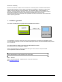
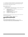
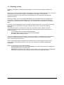
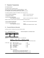
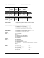
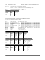
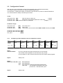
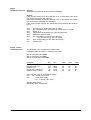
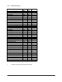
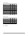
Manual
Data Transfer:
Profibus DP
Single Electronic Controller SC
Type: R8200
ELOTECH Industrieelektronik GmbH
Verbindungsstraße 27
D - 40723 HILDEN
FON +49 2103 / 255 97 0
FAX +49 2103 / 255 97 29
www.elotech.de
Email: [email protected]
Manual: SC-PB-EN
Version: 04/13
©Elotech GmbH
Seite 1 / 22
Content:
1.
Interface, general.....................................................................................................................................3
1.1 Line routing, screening and measures to combat interference voltage...............................................4
1.2 Shielding of lines..................................................................................................................................5
1.3 Connection guide ...............................................................................................................................6
2. Parameter Transmission .......................................................................................................................8
2.1 Process Reflection (Standard).............................................................................................................8
2.1.1 From master to slave: Transfer of Setpoint 1 and Control word .................................................8
2.1.2 From slave to master: Transfer of the process data ..................................................................9
2.1.3 From master to slave: Example; transfer of setpoint 1 and control word .................................10
2.2 Configuration Channel.......................................................................................................................11
2.2.1 Configuring of the parameters via the configuration channel......................................................11
2.2.2 Parametercodes (1).....................................................................................................................13
2.2.3 Transmission example: Configuration channel, Instruction code: 10 H.....................................15
2.2.4 Transmission example: Configuration channel, Instruction code: 20 H.....................................16
2.2.5 Transmission example: Configuration channel, Instruction code: 21 H.....................................17
2.3 Process Reflection (Standard) and Configuration Channel...........................................................18
2.4 Process Reflection (Extended) ........................................................................................................19
2.4.1 Process Value Transmission.......................................................................................................19
2.4.2 Output: Act. Temperature Process Value ...................................................................................20
2.5 Process Reflection (Extended) and Configuration Channel..........................................................21
Manual: SC-PB-EN
Version: 04/13
©Elotech GmbH
Seite 2 / 22
Disclaimer of liability
We have checked the contents of the document for conformity with the hardware and software
described. Nevertheless, we are unable to preclude the possibility of deviations so that we are
unable to assume warranty for full compliance. The information given in the publication is,
however, reviewed regularly. Necessary amendments are incorporated in the following editions.
We would be pleased to receive any improvement proposals which you may have.
This document may not be passed on nor duplicated, nor may its contents be used or disclosed
unless expressly permitted.
1. Interface, general
The control unit SC (slave) is equipped with a PROFIBUS DP interface.
The PROFIBUS -interface allows the slave to be monitored and controlled by a PROFIBUS master.
The data transfer between the slave and master takes place with the aid of the PROFIBUS-DP-protocol
acc. to EN 50170.
The communication is always controlled by the PROFIBUS-DP master.
Each slave has it’s own PROFIBUS- address.
If there are transmission or other errors detected by the slave, it doesn’t accept this data.
The old parameter values are still valid.
Please take attention to the manual of the slave (SC).
GDS - data file:
Will be delivered by Single Temperiertechnik, Hochdorf (Germany).
See: www.single-temp.de
Manual: SC-PB-EN
Version: 04/13
©Elotech GmbH
Seite 3 / 22
1.1
Line routing, screening and measures to combat interference voltage
This chapter deals with line routing in the case of bus, signal and power supply lines, with the
aim of ensuring an EMC- compliant design of your system.
General information on line routing
- Inside and outside of cabinets
In order to achieve EMC- compliant routing of the lines, it is advisable to split the lines into the
following line groups and to lay these groups separately.
Group A:
Group B:
Group C:
•shielded bus and data lines (e.g. for PROFIBUS-DP, RS232C and printers etc.)
•shielded analogue lines
•unshielded lines for DC voltages ≥ 60 V
•unshielded lines for AC voltage ≥ 25 V
•coaxial lines for monitors
•unshielded lines for DC voltages ≥ 60 V and ≥ 400 V
•unshielded lines for AC voltage ≥ 24 V and ≥ 400 V
•unshielded lines for DC voltages > 400 V
The table below allows you to read off the conditions for laying the line groups on the basis of the
combination of the individual groups.
Line laying instructions as a function of the combination of line groups:
Group A
Group B
Group C
Group A
1
2
3
Group B
2
1
3
Group C
3
3
1
1) Lines may be laid in common bunches or cable ducts.
2) Lines must be laid in separate bunches or cable ducts (without minimum clearance).
3) Lines must be laid in separate bunches or cable ducts inside cabinets but on separate cable
racks with at least 10 cm clearance outside of cabinets but inside buildings .
Manual: SC-PB-EN
Version: 04/13
©Elotech GmbH
Seite 4 / 22
1.2
Shielding of lines
Shielding is intended to weaken (attenuate) magnetic, electrical or electromagnetic interference
fields.
Interference currents on cable shields are discharged to earth via the shielding bus which is connected
conductively to the chassis or housing. A low-impedance connection to the PE wire is
particularly important in order to prevent these interference currents themselves becoming an
interference source.
Wherever possible, use only lines with braided shield. The coverage density of the shield should
exceed 80 %. Avoid lines with foil shield since the foil can be damaged very easily as the result
of tensile and compressive stress on attachment. The consequence is a reduction in the shielding
effect.
In general, you should always connect the shields of cables at both ends. The only way of achieving
good interference suppression in the higher frequency band is by connecting the shields at
both ends.
The shield may also be connected at one end only in exceptional cases. However, this then
achieves only an attenuation of the lower frequencies. Connecting the shield at one end may be
more favourable if
•
it is not possible to lay an equipotential bonding line
•
analogue signals (a few mV resp. mA) are to be transmitted
•
foil shields (static shields) are used.
In the case of data lines for serial couplings, always use metallic or metallised plugs and connectors.
Attach the shield of the data line to the plug or connector housing. Do not connect the shield
to a pin of the multi pole connector!
If there are potential differences between the earthing points, a compensating current may flow
via the shield connected at both ends. In this case, you should lay an additional equipotential
bonding line.
Please note the following points when shielding:
•
Use metal cable clips to secure the shield braiding. The clips must surround the shield over a
large area and must have good contact.
•
Downstream of the entry point of the line into the cabinet, connect the shield to a shielding bus.
Continue the shield as far as the module, but do not connect it again at this point!
Manual: SC-PB-EN
Version: 04/13
©Elotech GmbH
Seite 5 / 22
1.3
Connection guide
Note: Only in PROFIBUS- technology trained personnel following the safety regulations
may do the PROFIBUS - connections.
It is essential, that one has well experience in installing a profibus device.
Please look to the FAQ-list.
You will require the following components to connect the slave:
•
Connector for Profibus connection to the slave
•
PROFIBUS cable (this cable is generally already installed on site!)
•
GSD file and User Manual
•
Project planning tool for the PROFIBUS-DP
It is essential, that you perform the following during connecting in order to ensure that
the slave operates correctly:
PROFIBUS- Connections:
Connect the slave with the PROFIBUS. Take care to the terminals.
Terminals (SC):
Terminating-Resistors (Tol. +/-2%)
The terminals Vp and GND have
to be used to connect the
terminating-resistors.
There is no further load allowed.
70
RxTx
N
71
RxTx
P
72
CNT
220R
73
Vp
+5V
74
Gnd
390R
390R
Manual: SC-PB-EN
Version: 04/13
©Elotech GmbH
Seite 6 / 22
PROFIBUS – Adjustments:
Adjust the following parameters (slave):
See menu: ”setup interface”
Parameter „Protocol“:
Profibus-DP
The slave has to be equipped with a PROFIBUS-modul
Type: M8200-ProfibusDP, Single Art.No.: 18152
Otherwise the warning “Module not available” will be displayed.
Parameter „interface address“:
Profibus- address
Parameter „baudrate“,
No adjustment possible.
The baud rate will detected and monitored automatically.
Warning: „no baud rate is detected”
Line “State”: Profibus- status is displayed
PROFIBUS - Status:
Data Exchange:
The slave is in the data-exchange-modus.
The communication is OK.
The data-exchange with the master takes place.
Wait_Prm:
The bus is detected. The slave is waiting until the master has
programmed the slave. This happens automatically.
Wait Cfg:
The slave expects it`s configuration taken through the master.
This takes place automatically.
?:
The slave is not connected to the bus correctly.
E.g.:- Maybe there is a wiring error.
- The master is not active.
- The protocol isn't selected in the right way.
Error xxx:
Slave: Hardware error. No communication possible.
Please return the slave.
The controller-function of the slave itself is further possible.
Manual: SC-PB-EN
Version: 04/13
©Elotech GmbH
Seite 7 / 22
2. Parameter Transmission
The Communication:
The master sends it´s data to the slave.
After this the slave sends an answer to the PROFIBUS DP - master.
This takes place cyclic and will be controlled by the master.
The configuration of the slave takes place with the help of the GSD-file.
The following standard- modules are available for the slave (type: SC):
- Process Reflection (Standard):
Module: „SvL/SC Process Data“
- Configuration Channel:
Module: „Parameter Channel“
- Process reflection (Standard)
and Configuration Channel:
Module: „SvL/SC Process Data + Parameter“
Software version V34/08 and higher includes the following extended moduls:
- Process Reflection (Extended):
Module: „SvL/SC Process Data Extended“
- Process reflection (Extended)
and Configuration Channel:
2.1
Module:
„SvL/SC Process Data Extended + Param“
Process Reflection (Standard)
Parameter transfer according to the process reflection modul
2.1.1
From master to slave:
Transfer of Setpoint 1 and Control word
Byte 1
Byte 2
Byte 3
Setpoint
High Byte
Setpoint
Low Byte
Control word
Setpoint:
The parameter value consists out of 2 data bytes.
Dec.
Hex.
High-Byte Low-Byte
Example:
Setpoint (°C): 230
00E6
00
E6
Means 230°C or 230°F or 23,0°C, depending of the selected measuring range.
Control word:
Bit 0:
Bit 1:
Bit 2:
Bit 3:
Bit 4:
Bit 5:
Bit 6:
Bit 7:
slave „on“ or „off“
slave „cool down“ and „off“
sensor internal or external
suction mode
evacuating mode
2nd. setpoint
auto tuning *)
---
1 = on
1 = on
1 = external
1 = on
1 = on
1 = on
1 = on
*) Bit 6 „Auto tuning“:
The changing from „0“ to „1“ forces one auto tuning action.
Before starting another auto tuning function, set bit 6 first to „0“ again.
If Bit 6 is set on „0“ the running auto tuning circle stops.
You can read the actual state of auto tuning in the process data state.
Manual: SC-PB-EN
Version: 04/13
©Elotech GmbH
Seite 8 / 22
2.1.2
From slave to master:
Transfer of the process data
Byte 1
Byte 2
Byte 3
Byte 4
Byte 5
StatusInstruction
Actual
Process
temperature,
Pre-flow
High Byte
Actual
Process
temperature,
Pre-flow
Low Byte
Process
temperature,
Back-flow
High Byte
Process
temperature,
Back-flow
Low Byte
Byte 6
Byte 7
Byte 8
Byte 9
Byte 10
Byte 11
flow
High Byte
flow
Low Byte
Pressure
High Byte
Pressure
Low Byte
Power
High Byte
Power
Low Byte
Byte 12
Byte 13
Byte 14
Byte 15
Byte 16
Byte 17
Filmtemperature
High Byte
Filmtemperature
Low Byte
Controller
output
0x9C...0x64
Alarms 1
Alarms 2
Status
Definition
„Status instruction“ :
Indicates, if a range error has been detected, when writing the setpoint.
0 = setpoint value OK.
1 = setpoint value faulty
Definition „Flow-Through“ :The sending value is to be interpreted without or with a decimal place.
This depends on the system configuration.
For example: Send: 50 - Display Flow-Through = 50 l/min.
For example: Send: 50 - Display Flow-Through = 5.0 l/min.
For example: Send: 504 - Display Flow-Through = 50,4 l/min.
Definition „Pressure“ :
Definition „Work“ :
Definition
„Alarms 1“ :
Definition
„Alarms 2“ :
Definition
„Status“ :
Manual: SC-PB-EN
The sending value has to be interpreted with or without a decimal point.
For example: Send: 50 - Display Preasure = 5.0 bar
For example: Send: 70 - Display Work = 7.0 kW
Bit 0 = collecting alarm
Bit 1 = alarm 1
Bit 2 = --Bit 3 = alarm pump (phase, rotation direction)
Bit 4 = alarm filling level
Bit 5 = alarm flow transducer and through-flow
Bit 6 = system error
Bit 7 = auto tune error
Bit 0 = alarm
Bit 1 = alarm
Bit 2 = alarm
Bit 3 = alarm
Bit 4 = alarm
Bit 5 = alarm
Bit 6 = --Bit 7 = ---
pre-flow
back-flow
film-temperature
sensor breakage (act. sensor)
pressure
delta T
(monitoring the difference between pre- and backflow)
Bit 0 = slave on / off
Bit 1 = slave „cool down“ and „out“
Bit 2 = sensor internal or external
Bit 3 = suction mode
Bit 4 = evacuating mode
Bit 5 = 2nd. setpoint
Bit 6 = auto tuning
Bit 7 = hand- or remote-operation
Version: 04/13
1 = on
1 = on
1 = external
1 = on
1 = on
1 = on
1 = on
1 = hand
©Elotech GmbH
Seite 9 / 22
2.1.3
From master to slave:
Example; transfer of setpoint 1 and control word
Byte 1 + 2:
The setpoint 50°C should be send to the slave.
Setpoint: 50 decimal = 0x0032 hexadecimal as a 16 Bit integer-value
Byte 3:
The slave should be switched „on“ (Bit 0 = 1).
Byte 1
Byte 2
Byte 3
Setpoint
High Byte
Setpoint
Low-Byte
Control word
0x00
0x32
0x01
Answer from slave to master: Transmission of the process reflection
The slave sends the following parameter-values:
Byte 1:
Byte 2 + 3:
Byte 4 + 5:
Byte 6 + 7:
Byte 8 + 9:
Byte 10 + 11:
Byte 12 + 13:
Byte 14:
Byte 15:
Byte 16:
Byte 17:
status instruction
pre-flow temperature
back-flow temperature
through-flow
pressure
through-flow power
film-temp.
output ratio
alarms 1
alarms 2
status
the last instruction was ok.
55
decimal = 0x0037 hexadecimal as a 16 Bit integer-value
50
decimal = 0x0032 hexadecimal as a 16 Bit integer-value
280
decimal = 0x0118 hexadecimal as a 16 Bit integer-value
11,4
decimal = 0x0072 hexadecimal as a 16 Bit integer-value
232,0 decimal = 0x0910 hexadecimal as a 16 Bit integer-value
46
decimal = 0x002E hexadecimal as a 16 Bit integer-value
-33
decimal = 0xDF hexadecimal as a 8 Bit integer-value
no alarm
film-alarm is active
slave is switched „on“
Byte 1
Byte 2
Byte 3
Byte 4
Byte 5
StatusInstruction
Actual
Process
temperature,
Pre-flow
High Byte
Actual
Process
temperature,
Pre-flow
Low Byte
Process
temperature,
Back-flow
High Byte
Process
temperature,
Back-flow
Low Byte
0x00
0x32
0x00
0x37
Byte 6
Byte 7
Byte 8
Byte 9
Byte 10
Byte 11
Trough-flow
High Byte
Trough-flow
Low Byte
Pressure
High Byte
Pressure
Low Byte
Trough-flow
Power
High Byte
Trough-flow
Power
Low Byte
0x01
0x18
0x00
0x72
0x09
0x10
Byte 12
Byte 13
Byte 14
Byte 15
Byte 16
Byte 17
Filmtemperature
High Byte
Filmtemperature
Low Byte
Controller
output
Alarms 1
Alarms 2
Status
(read)
0x00
0x2F
0xDF
0x00
0x04
0x01
0x00
Manual: SC-PB-EN
Version: 04/13
©Elotech GmbH
Seite 10 / 22
2.2
Configuration Channel
With the help of the configuration channel each parameter can be addressed individually.
The master is allowed to read and to change all allowed parameters.
The instruction- or parameter transfer is executed in both directions by means of defined data blocks.
The communication is always controlled by the master.
Terms
Instruction-code [BC]:
"tells" the device, what to do
(1 Byte)
Parameter-code [PC]:
designates each individual parameter of the slave
(1 Byte)
Parameter-value [PW]:shows the value of a parameter
(3 Byte)
Parameter ranges
Instruction-code
Parameter-code
Parameter-value
[BC]:
[PC]:
[PW]:
0x10, 0x20, 0x21
0x00...0xFF
16 bit integer, real numerical value PWH and PWL and dec.point PWK
Parameter-value High-Byte [PWH]
Parameter-value Low- Byte [PWL]
Dec. point
[PWK]
2.2.1
Configuring of the parameters via the configuration channel.
Byte 1
Byte 2
Byte 3
Byte 4
Byte 5
Byte 6
Byte 7
Byte 8
Current
number
always:
Instruction
code
always:
0x01
BC
0x10, 0x20 or
0x21
0x00
Parametervalue
PWH
High-Byte
Parametervalue
PWL
Low-Byte
Dec. point
0x00 ... 0xFF
Parametercode
PC
0x00 ... 0xFF
Byte 1
Current Number:
Byte 2:
PWK
0x00 ... 0xFF
For every new task the master should preset a current number.
This number will be repeated from the slave with every answer.
So it is possible, to find out which instruction and which answer belong together.
Always 0x01
Byte 3
Instruction code, BC: 0x10 : Read parameter
0x20 : Write parameter
0x21 : Write parameter and store with power fail protection
Take care:
The EAROM or EEPROM of the slave
permits max. 1.000.000 write cycles.
Byte 4:
Manual: SC-PB-EN
Always 0x00
Version: 04/13
©Elotech GmbH
Seite 11 / 22
Byte 5
Parameter code, PC: Enquiry:
Addresses the parameter which should be configured.
Answer:
If the read-proceeding to the slave was OK., then, in the answer of the slave,
byte 5 shows the parameter-code PC.
If the write-proceeding to the slave was OK., then, in the answer of the slave,
byte 5 shows the value 00H (acknowledge).
If the communication was not OK., the following error-warnings are shown in
byte 5:
03 H
04 H
05 H
06 H
08 H
09 H
FEH
FFH
Byte 6, 7 und 8
Parameter value:
- Procedure error (instruction code not valid)
- Non-compliance with specified range (value to low or to high)
- Byte 2 ≠ 1
- The addressed parameter is a read-only parameter
- Parameter-code not valid
- It is not possible, to execute the instruction
(e.g., the auto tuning can´t be started)
- Error during writing into the power fail storage
- General error
The parameter value comprises three data bytes:
2 data byte (PWH and PWL), 1 data byte (dec.point).
Byte 6: Parameter value PWH
Byte 7: Parameter value PWL
Byte 8: Comma (dec. point) PWK
Examples:
Dec.
Hex.
PWH
PWL
PWK
Process value (°C):
Setpoint (°C):
Output ratio, cooling (%)
Setpoint ramp (°C/min):
215
230
-16
2,2
00D7
00E6
FFF0
0016
00
00
FF
00
D7
E6
F0
16
00
00
00
FF
The parameter value is calculated as follows:
Dec.: 2,2 = 22 with 1 dec. point
Hex.:
= 0016 (PWH PWL)
= 01 (comma / dec. point)
Negative data values:
Built binary two´s complement.
Manual: SC-PB-EN
Version: 04/13
©Elotech GmbH
Seite 12 / 22
2.2.2
Parametercodes (1)
Parameter
Param.code
Attribute
1st setpoint
alarm limit
2nd setpoint
alarm to process
aqua timer
draining time
alarm flow
alarm pressure high
alarm pressure low
leak stop
testing time flow capacity
0x21
0x38
0x22
0x3a
0xa0
0xa1
0x3b
0x3e
0x3f
0xa7
0xaa
RW
RW
RW
RW
RW
RW
RW
RW
RW
RW
RW
regulation ratio
regulation ratio heating
regulation ratio cooling
XP- heating
TV- heating
TN- heating
XP- cooling
TV- cooling
TN- cooling
hyst. switch heating/cooling
switch cycle time heating
switch cycle time cooling
upper setpoint limit
lower setpoint limit
0x60
0x64
0x69
0x40
0x41
0x42
0x50
0x51
0x52
0x46
0x43
0x53
0x2c
0x2b
RO
RW
RW
RW
RW
RW
RW
RW
RW
RW
RW
RW
RW
RW
alarm film temperature
system closing temperature
alarm ∆T
temperature unit
external sensor logic
self-optimization
0x39
0xa2
0xa3
0x1b
0x1c
0x88
RW
RW
RW
RW
RW
RW
from process limit
0x3c
RW
setpoint ramp increasing
setpoint ramp decreasing
0x2f
0x2e
RW
RW
alarm 2
switch on hyst. cooling
switch off hyst. cooling
0x3d
0x5a
0x59
RW
RW
RW
*)
Others
*)
*)
*)
if cooling–off function (only) has been selected.
Manual: SC-PB-EN
Version: 04/13
©Elotech GmbH
Seite 13 / 22
Parametercodes (2a)
Parameter
parameter lock
cascade control
Param.code
0x85
0x33
Attribute
RW
RW
shut down temperature
act. value output: upper value
act. value output: lower value
0x93
0x87
0x89
RW
RW
RW
config. change logic
aqua timer start time
record. function: sample time
reclosing lockout
recipe selection
profile controller
0xa8
0xa9
0xd8
0x90
0X91
0x92
RW
RW
RW
RW
RW
RW
actual value offset int. sens.
actual value offset ext. sens.
act. value offset from process
act. value offset sens. to proc.
act. value offset film sensor
0xab
0xac
0xad
0xae
0xaf
RW
RW
RW
RW
RW
Param.code
0x10
0x12
0x13
0x14
0x15
0x16
0x17
0x20
0x8f
Attribute
RO
RO
RO
RO
RO
RO
RO
RO
RW
Others
Parameter-codes (2b)
Additional Parameters
process temperature
from process temperature
to process temperature
film temperature
flow
to process pressure
power
setpoint
device on/off
RW
RO
Others
= Read/Write
= Read Only
Manual: SC-PB-EN
Version: 04/13
©Elotech GmbH
Seite 14 / 22
2.2.3
Transmission example: Configuration channel, Instruction code: 10 H
The slave is asked to send the parameter „Process value, 10 H“ to the master.
The process value is 225 °C. 225 (Decimal) = 0xE1 (Hex)
Master to slave:
Current number:
Always:
Send parameter:
Always:
Parameter code (process value):
Parameter value (High-Byte):
Parameter value (Low -Byte):
Dec.point:
Dec.
1
1
16
0
16
0
0
0
Hex
0x01
0x01
0x10
0x00
0x10
0x00
0x00
0x00
Transmission to slave: 0x01, 0x01 0x10, 0x00, 0x10, 0x00, 0x00, 0x00
Slave to master:
Current number of instruction:
Always:
Send parameter:
Always:
Parameter code (process value):
Parameter value (High-Byte):
Parameter value (Low -Byte):
Dec. point:
Dec.
1
1
16
0
16 *)
0
225
0
Hex
0x01
0x01
0x10
0x00
0x10
0x00
0xE1
0x00
Transmission to master: 0x01, 0x01 0x10, 0x00, 0x10, 0x00, 0xE1, 0x00
*) Repetition of the parameter code (PC = 16), because the read-process was ok.
Manual: SC-PB-EN
Version: 04/13
©Elotech GmbH
Seite 15 / 22
2.2.4
Transmission example: Configuration channel, Instruction code: 20 H
The slave gets the instruction:
"Overtake parameter „prop.-band heating“ (parameter code: 40H, parameter value: 5,0 %)
and store into the RAM".
Master to slave:
Current number:
Always:
Instruction code:
Always:
Parameter code:
Parameter value (High-Byte):
Parameter value (Low -Byte):
Dec.point:
Dec.
2
1
32
0
64
0
50
1
Hex
0x02
0x01
0x20
0x00
0x40
0x00
0x32
0x01
Transmission to slave: 0x02, 0x01, 0x20, 0x00, 0x40, 0x00, 0x32, 0xFF
Slave to master:
Current number of instruction:
Always:
Instruction code:
Always:
Parameter code (Prop-band, heating):
Parameter value
(High-Byte):
Parameter value
(Low -Byte):
Dec. point:
Dec.
2
1
32
0
0 *)
0
0
0
Hex
0x02
0x01
0x20
0x00
0x00
0x00
0x00
0x00
Transmission to master: 0x02, 0x01, 0x20, 0x00, 0x00, 0x00, 0x00, 0x00
*)
If the slave has understood the instruction of the master, it answers always with the
parameter code (PC) = 00, because the writing-process was OK.
If there are transmission or other errors the slave answers with the corresponding error code.
Manual: SC-PB-EN
Version: 04/13
©Elotech GmbH
Seite 16 / 22
2.2.5
Transmission example: Configuration channel, Instruction code: 21 H
The slave gets the instruction:
"Overtake parameter setpoint 1 / SP1 = 200°C (parameter code: 21H) and store power fail safe into the
EEPROM“.
Master to slave:
Current number:
Always:
Instruction code:
Always:
Parameter code (SP1):
Parameter value (High-Byte):
Parameter value (Low -Byte):
Dec.point:
Dec.
3
1
33
0
33
0
200
0
Hex
0x03
0x01
0x21
0x00
0x21
0x00
0xC8
0x00
Transmission to slave: 0x03, 0x01, 0x21, 0x00, 0x21, 0x00, 0xC8, 0x00
Slave to master:
Current number of instruction:
Always:
Instruction code:
Always:
Parameter code:
Parameter value (High-Byte):
Parameter value (Low -Byte):
Dec. point:
Dec.
3
1
33
0
0 *)
0
0
0
Hex
0x03
0x01
0x21
0x00
0x00
0x00
0x00
0x00
Transmission to master: 0x03, 0x01, 0x21, 0x00, 0x00, 0x00, 0x00, 0x00
*)
If the slave has understood the instruction of the master, it answers always with the
parameter code (PC) = 00, because the writing-process was ok.
If there are transmission or other errors the slave answers with the corresponding error code.
Manual: SC-PB-EN
Version: 04/13
©Elotech GmbH
Seite 17 / 22
2.3
Process Reflection (Standard) and Configuration Channel
It is possible, to transmit process reflection and configuration channel simultaneously.
In this case the bytes of the configuration channel have to be fit together with the process reflection.
Master to slave:
Byte 1
Byte 2
Byte 3
Setpoint
High Byte
Setpoint
Low Byte
Control word
Byte 4
Byte 5
Byte 6
Byte 7
Byte 8
Byte 9
Byte 10
Byte 11
Current
number
always:
Instruction
code
BC
always:
Parametercode
PC
Parametervalue
PWH
High Byte
Parametervalue
PWL
Low Byte
Dec.point:
0x01
0x00
PWK
Slave to master:
Byte 1
Byte 2
Byte 3
Byte 4
Byte 5
StatusInstruction
Process
temperature,
Pre-flow
High Byte
Process
temperature,
Pre-flow
Low Byte
Process
temperature,
Back-flow
High Byte
Process
temperature,
Back-flow
Low Byte
Byte 6
Byte 7
Byte 8
Byte 9
Byte 10
Byte 11
flow
High Byte
flow
Low Byte
Pressure
High Byte
Pressure
Low Byte
Power
High Byte
Power
Low Byte
Byte 12
Byte 13
Byte 14
Byte 15
Byte 16
Byte 17
Filmtemperature
High Byte
Filmtemperature
Low Byte
Controller
output
Alarms 1
Alarms 2
Status
(read)
Byte 18
Byte 19
Byte 20
Byte 21
Byte 22
Byte 23
Byte 24
Byte 25
Current
number
always:
Instruction
code
BC
always:
Parametercode
PC
Parametervalue
PWH
High Byte
Parametervalue
PWL
Low Byte
Dec. point:
0x01
Manual: SC-PB-EN
0x00
Version: 04/13
©Elotech GmbH
PWK
Seite 18 / 22
2.4
Process Reflection (Extended)
Software Version 34/08 and higher
profile controller from SW-Version 04/13
2.4.1
Process Value Transmission
The slave gets it’s actual temperature value (controller value) via PROFIBUS from the master.
Transfer of the process data SC, extended:
From master to slave: Transmission of setpoint, control word recipe selection and act. process
temperature value
Byte 1
Byte 2
Byte 3
Byte 4
Byte 5
Byte 6
Byte 7
Setpoint
High Byte
Setpoint
Low Byte
Control word
Process
value
via Profibus
High Byte
Process
value
via Profibus
Low Byte
start profile
controller
0 = Stop
1= Start
Recipe
selection
1..10
Setpoint:
The parameter value consists out of 2 data bytes.
Example:
Dec.
Hex. High-Byte Low-Byte
Setpoint (°C):
230
00E6 00
E6
Means 230°C or 230°F or 23,0°C, depending of the selected measuring range.
Control word:
Act. temp. value
in reserve
profile controller
starting:
recipe selection:
129
110
0
0
4
81
006E
0000
81 Slave on, process value via Profibus
6E
00
00
00
00
04
00
04
profile controller stopped
recipe 4 selected.
Adjustment of recipe selection is only possible when profile controller is stopped, otherwise error message “setpoint value faulty” in
status byte „Status instruction“.
Control word,
Byte 3:
Bit 0:
Bit 1:
Bit 2:
Bit 3:
Bit 4:
Bit 5:
Bit 6:
Bit 7:
slave „on“ or „off“
slave „cool down“ and „off“
sensor internal or external
suction mode
evacuating mode
2nd. setpoint
autotuning
Actual process temperature
via PROFIBUS
1 = on
1 = on
1 = external
1 = on
1 = on
1 = on
1 = on
1 = on
0 = process value selection acc. to bit 2
Select Parameter „external sensor“ with the help of the control word (Byte 3):
Sensor, internally /
externally
Bit 2 =
0
1
0
Act. Process value
via Profibus
Bit 7 =
0
0
1
1
1
Manual: SC-PB-EN
Parameter:
external sensor
Off:
Controlling: int. sensor
On:
Controlling: ext. sensor
Sensor Profibus:
Act. process temp. value (Byte 4 and 5)
will be used for temp. controlling
Sensor Profibus:
Act. process temp. value (Byte 4 and 5)
will be used for temp. controlling
Version: 04/13
©Elotech GmbH
Seite 19 / 22
If „Sensor Profibus“ is selected as the actual process temperature value, it will be switched over to
„internal process value“ automatically, if:
1. The act. process value is lower or higher than the selected range (-30°C / 400°C).
2. The Profibus- connection is disturbed.
3. The Remote-operation is not active.
Type „SC – Professional“:
2.4.2
The selection of an external sensor is not possible via external contact
S1, if the parameter „External Sensor“ is set to „Sensor Profibus“.
Output: Act. Temperature Process Value
The following act. temperature process values can be send to PROFIBUS and to the analogue output
(Terminals 40-42).
Go to menu: “setup: Device functions”.
The selection takes place with parameter „Temp. output / PB”
Select:
„Actual controller sensor“ → The actual controller process value (either int. or ext. sensor) will be send to
the analogue output and the PROFIBUS.
„External Sensor“
„Internal Sensor“
→ The value of the external sensor will be send to the analogue output and to
the PROFIBUS. If the external sensor has a sensor breakage, the value of
the internal sensor will be send to the output automatically.
→ The value of the internal sensor will be send to the analogue output and to
the PROFIBUS.
Transmission of the Process Data SC, extended:
Slave to Master:
Byte 1
Byte 2
Byte 3
Byte 4
Byte 5
StatusInstruction
Process value = act.
controller sensor
or
ext./int. sensor
High Byte
Process value = act.
controller sensor
or
ext./int. sensor
Low Byte
Process
temperature,
Back-flow
High Byte
Process
temperature,
Back-flow
Low Byte
Byte 6
Byte 7
Byte 8
Byte 9
Byte 10
Byte 11
flow
High Byte
flow
Low Byte
Pressure
High Byte
Pressure
Low Byte
Power
High Byte
Power
Low Byte
Byte 12
Byte 13
Byte 14
Byte 15
Byte 16
Byte 17
Filmtemperature
High Byte
Filmtemperature
Low Byte
Controller
output
Alarms 1
Alarms 2
Status
(read)
Byte 18
Byte 19
Byte 20
Byte 21
Byte 22
Byte 23
in reserve 1
in reserve 2
in reserve 3
in reserve 4
in reserve 5
in reserve 6
In reserve: not used.
Manual: SC-PB-EN
Version: 04/13
©Elotech GmbH
Seite 20 / 22
2.5
Process Reflection (Extended) and Configuration Channel
Software Version 34/08 and higher
profile controller from SW-Version 04/13
Process reflection and Configuration Channel can be transmitted simultaneously.
The bytes of the configuration channel will be added to the process reflection.
Master to Slave:
Byte 1
Byte 2
Byte 3
Byte 4
Byte 5
Byte 6
Byte 7
Setpoint
High Byte
Setpoint
Low Byte
Control word
Process
value
via Profibus
High Byte
Process
value
via Profibus
Low Byte
start profile
controller
0 = Stop
1= Start
Recipe
selection
1..10
Byte 8
Byte 9
Byte 10
Byte 11
Byte 12
Byte 13
Byte 14
Byte 15
Current
number
always:
Instructioncode
always:
Parametercode
PC
BC
0x00
Parametervalue
PWL
Low-Byte
Dec. point
0x01
Parametervalue
PWH
High-Byte
PWK
Slave to Master:
Byte 1
Byte 2
Byte 3
Byte 4
Byte 5
StatusInstruction
Process value = act.
controller sensor
or
ext./int. sensor
High Byte
Process value = act.
controller sensor
or
ext./int. sensor
Low Byte
Process
temperature,
Back-flow
High Byte
Process
temperature,
Back-flow
Low Byte
Byte 6
Byte 7
Byte 8
Byte 9
Byte 10
Byte 11
flow
High Byte
flow
Low Byte
Pressure
High Byte
Pressure
Low Byte
Power
High Byte
Power
Low Byte
Byte 12
Byte 13
Byte 14
Byte 15
Byte 16
Byte 17
Filmtemperature
High Byte
Filmtemperature
Low Byte
Controller
output
Alarms 1
Alarms 2
Status
(read)
Byte 18
Byte 19
Byte 20
Byte 21
Byte 22
Byte 23
in reserve 1
in reserve 2
in reserve 3
in reserve 4
in reserve 5
in reserve 6
Byte 24
Byte 25
Byte 26
Byte 27
Byte 28
Byte 29
Byte 30
Byte 31
Current
number
always:
Instructioncode
always:
Parametercode
PC
BC
0x00
Parametervalue
PWL
Low-Byte
Dec. point
0x01
Parametervalue
PWH
High-Byte
Manual: SC-PB-EN
Version: 04/13
©Elotech GmbH
PWK
Seite 21 / 22
Manual: SC-PB-EN
Version: 04/13
©Elotech GmbH
Seite 22 / 22