1
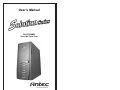
User’s Manual
SLK3700AMB
Super Mid Tower Case
Disclaimer
This manual is intended only as a guide for Antec's Computer Enclosures. For more
comprehensive instructions on installing your motherboard and peripherals, please refer
to the user's manuals which come with your components and drives.
SLK3700AMB - Super Mid Tower Case
Power Supply
The power supply installed in this case comes with a main power switch. Make sure you
turn the switch to the ON ( I ) position before you boot up your computer for the first time.
In normal operation there is no need to turn the switch to the OFF (O) position since the
power supply is equipped with a soft on/off feature which turns your computer on and off
through the soft switch on your computer case. You may occasionally need to turn the
switch to the OFF position should your computer crash and you cannot shut it down through
use of the soft switch.
[Applicable only to models designed for sale in the European Union: Solution power
supply models designed for the EU include Power Factor Correction (PFC) circuitry in
accord with European standard regulation code EN61000-3-2. By altering the input current
wave shape, PFC improves the power factor of the power supply and results in increased
energy efficiency, reduced heat loss, prolonged life for power distribution and consumption
equipment, and improved output voltage stability.]
Note (not applicable to models designed for the European Union): Check the red
power supply voltage switch setting before installation. It should be the same as your local
power voltage (115V for North America, Japan, etc. and 230V in Europe and many other
countries). Change the voltage setting if necessary. Failure to take this precaution could
result in damage to your equipment and could void your warranty.
Set Up
1.
Take the case out of the box.
2.
Remove the Styrofoam.
3.
Remove the plastic bag.
4.
Place the case upright on a stable flat surface with the power supply fan at the back
facing you .
5.
Remove the screws from the right side panel.
6.
There are two latches on the side panel. Press the latch release on each. The latches
will pop up to about 65 degrees. Push the latches out to the 90 degree position to fully
disengage the latches and swing open the panel.
7.
Inside the case you should see the power supply, some wiring with marked connectors
(USB, PWR etc.), an installed I/O panel, a power cord. You will also find a bag of
hardware (drive rails, screws, brass standoffs, plastic stands, etc.)
8.
Place the case with the front bezel facing you and press the release tabs on the bottom
of the bezel to remove the front bezel. Set the bezel aside in a safe place.
Motherboard Installation
This manual is not designed to cover CPU, RAM, or expansion card installation. Please
consult your motherboard manual for specific mounting instructions and troubleshooting.
1.
Lay the case down so that the open side is up. You should be able to see the drive
cage and power supply.
1
2.
3.
4.
5.
6.
7.
8.
Make sure you have the appropriate I/O panel for your motherboard. If the panel
provided is not suitable for your motherboard, please contact your motherboard
manufacturer for the correct I/O panel.
Line up motherboard with the standoff holes, and determine which ones line up and
remember where they are. Not all motherboards will match with all of the provided
screw holes, and this is not necessary for proper functionality. (In other words there
will likely be extra holes.) Some standoffs may be pre-installed for your convenience.
Lift up and remove your motherboard.
Screw in the brass standoffs to the threaded holes that line up with your motherboard.
Place your motherboard on the brass standoffs.
Screw in your motherboard to the standoffs with the provided Phillips-head screws.
Your motherboard is now installed.
Power/LED Connections
The Antec Solution Series SmartPower power supply is an ATX12V form factor power
supply. An ATX12V power supply has a single 20-pin Main Power Connector, a 6-pin
AUX Power Connector, and a 4-pin +12V Power Connector for the motherboard. It also
comes with five to seven 4-pin Peripheral Power Connectors and one to two 4-pin Floppy
Drive Power Connectors for your drives. It is backwards compatible to previous ATX form
factor power supplies. If your motherboard does not support the AUX Power Connector or
the +12V Power Connector, you can still use this power supply.
The power supply is also equipped with a 3-pin fan signal connector. Connect it to one of
the fan connectors on your motherboard. You may monitor the speed of the rear power
supply fan through your motherboard BIOS or through the monitoring software that comes
with your motherboard. Note: The speed of the fan may be as low as 1500 RPM when
temperatures are low. At these speeds some motherboards may not be able to properly
detect the fan speed and may generate false warnings of fan failure. Please refer to your
motherboard manual for proper fan monitoring set up.
1.
Connect the 20-pin ATX power connector (and AUX or +12V connectors if
appropriate) to your motherboard.
2.
Reset switch (labeled RESET SW) connects to your motherboard at the RST
connector. The label should be facing the front of the case, and for all of the
following connectors as well.
3.
Power Switch (labeled POWER SW) connects to the PWR connector on the
motherboard.
4.
Speaker connector (labeled SPEAKER) is behind the PWR connector.
5.
The Power LED, Hard Drive LED, and LED I & LED II connectors all share a single
ribbon cable. Attach the Power LED (labeled POWER) and HDD LED connectors to
the appropriate headers on your motherboard. The LED I and LED II connectors may
be used as you see fit for such purpose as SCSI LED, Message LED, etc. as supported
by your motherboard, expansion cards, and peripherals.
USB Connection
There are 8 wires with connectors coming from the front mounted USB ports of the case.
1.
Locate the internal USB header on your motherboard. It consists of 10-pins in two
rows.
Note: On some motherboards one or two pins may be marked as NC. This indicates
no contact. It is an empty pin. You don't need to use it. On some motherboards one
pin may be missing on either one or both rows. Don't worry about it. You only need
8 pins to connect to.
2
2.
3.
4.
5.
Consult your motherboard manual to get each of the pin-out positions.
Power Pins: There are two power pins, one on each row. They are usually marked as
Power, Vcc or +5V. Connect the two +5V connectors to the two power pins. Each
connector can go to either pin.
Ground Pins: There are two ground pins, one on each row. They are usually marked
as GROUND or GND. Connect the two GROUND connectors to the two ground pins.
Each connector can go to either pin.
Note: On some motherboards, there may be two ground pins on one row. You don't
need to use all of them. Make sure to connect one ground pin on each row.
Data Pins: There are two plus data pins, one on each row, and two minus data pins,
one on each row. They are usually marked as USBD2+, USBD3+ and USBD2-,
USBD3- or USBP2+, USBP3+ and USBP2-, USBP3- respectively.
a. Connect the 1 +D connector to any of the two plus data pins. It can go to either
of the plus pins.
b. Connect the 1 -D connector to the minus data pin in the same row as the plus data
pin that 1 +D connector has just connected to.
c. Repeat the same procedures to connect the 2 +D and 2 -D to the motherboard.
Make sure they are in the same row.
3.5" Device Installation
There are two 3.5" drive cages inside the case. The upper one can hold 2 external 3.5"
drives, and the lower one can hold 5 internal 3.5" drives. Release the upper cage by pulling
the quick release lever towards the rear of the case. Unscrew the thumbscrew on the bottom
of the lower cage and press the release tab to release the drive cage. To remove the lower
drive cage pull the drive cage out of the opening. Note: Many removable drive cages had
you pull the cage towards the back of the case. This is NOT the case for the lower drive
cage. Put both cages on a flat surface.
1.
Mount your floppy drives or other external devices into the upper cage.
2.
Mount your hard drive or other internal 3.5" devices into the lower drive cage with
the special screws provided. Don't over-tighten the screws since the hard drives are
mounted to the cage by the screws through the rubber grommets.
3.
Slide and lock both drive cages back into the case.
4.
Find a small 4-pin white connector on the power supply and connect it to the male
4-pin connector on the floppy drive.
5.
Connect a large 4-pin white connector from the power supply to the 4-pin connector
on each of the other devices.
Note: If you want to install a 120mm fan to the front of the case, you should do so
before re-installing the lower drive cage in the case. See Fan Installation section for
details.
5.25" Device Installation
There are four 5.25" drive bays, each covered with a ventilated metal cover and an EMI
Contact plate as one Assembly. For your convenience the factory has prepared the top drive
bay without the metal plate so that it is ready for immediate installation. To install a 5.25"
drive in another bay:
1.
Bend the EMI Contact plate covering the Lower half of the selected drive bay 90
degrees inwards to form a drive support. (See picture 1.)
2.
Carefully twist the assembly covering the upper half of the selected drive bay back
and forth until it breaks off, and remove it.
Note: Be careful of the newly exposed metal where the assembly was attached as
these areas are likely to be sharp. Don't break off the metal assemblies covering the
drive bays that you are not using now. Antec has included two EMI cover plates in
3
3.
4.
5.
6.
7.
the toolbox in case you later need to cover drive bays again.
Take two drive rails and mount them to the sides of your
5.25" device.
Slide the device into the drive bay until you hear a click.
Repeat the same procedure to install your other drives.
Connect a large 4-pin white connector from the power
supply to the male 4-pin connector on each device.
After you have finished installing devices, carefully use
your thumbs to push the plastic drive bay covers off the
bezel and re-attach the bezel to the case.
Picture 1.
Data Cable Connection
After you have connected the devices to the power supply, you need to connect the data
cables between the devices and the motherboard. The data cables are not included with the
case; we include this information only as an aid.
1.
For hard drives and CD-ROM's, use the 40-pin IDE ribbon cables. For floppy drives,
use the 34-pin ribbon cables. These should come with your devices and have a red
strip on side indicating pin number 1. When you connect a ribbon cable to a device,
make sure that the red strip is on pin 1, usually toward the power connector.
2.
The side that attaches to devices should be the side that has 2 connectors. This will
enable you to connect another device if you wish.
3.
Connect the far end of the cable to your motherboard on the IDE port, either IDE 1
or IDE 2, or the FLOPPY port.
Fan Installation
The case has one 120mm cooling fan mounted in the rear and one optional 120mm cooling
fan mount in the front.
The rear fan is installed so that the air is blowing out of the case.
Connect a large 4-pin white connector from the power supply to the male 4-pin connector
on the fan.
The front fan should be installed so that the air is blowing into the case from the front.
It is recommended that you install the fan while the lower 3.5" drive cage is removed from
the case.
1.
Drop the fan into the fan cage and push it in until it snaps in.
2.
If you're using a 4-pin fan connect a large 4-pin white connector from the power
supply to the male 4-pin connector on the fan. If you're using a 3-pin fan connect the
3-pin connector to a motherboard fan header.
Washable Air Filter Maintenance
We recommend washing the air filter as often as required by environmental conditions, at
least once a month initially. Failure to keep the installed air filter clean will result in higher
system temperatures and possible stability problems.
Antec Quality 3-Year parts and labor warranty (AQ3)
See details at:
http://www.antec-inc.com/support_warranty.html
http://www.antec-europe.com/warranty_uk.html
4