1
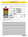
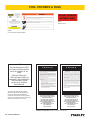
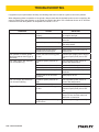
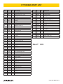
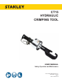
CT15
HYDRAULIC
CRIMPING TOOL
USER MANUAL
Safety, Operation and Maintenance
© 2014 Stanley Black & Decker, Inc.
New Britain, CT 06053
U.S.A.
58547 10/2014 Ver. 6
TABLE OF CONTENTS
SAFETY SYMBOLS...................................................................................................................................................4
SAFETY PRECAUTIONS...........................................................................................................................................5
TOOL STICKERS & TAGS.........................................................................................................................................6
HOSE TYPES.............................................................................................................................................................7
HOSE RECOMMENDATIONS...................................................................................................................................8
FIGURE 1. TYPICAL HOSE CONNECTIONS........................................................................................................8
HTMA REQUIREMENTS............................................................................................................................................9
OPERATION.............................................................................................................................................................10
FIGURE 2. OC/CC SETTING ..............................................................................................................................10
TOOL PROTECTION & CARE.................................................................................................................................13
TROUBLESHOOTING.............................................................................................................................................14
SPECIFICATIONS....................................................................................................................................................15
CRIMPING DATA......................................................................................................................................................15
CT15036GN PARTS ILLUSTRATION......................................................................................................................16
CT15036GN PARTS LIST........................................................................................................................................17
IMPORTANT
To fill out a Product Warranty Validation form, and for information on your warranty,
visit Stanleyhydraulics.com and select the Company tab, Warranty.
(NOTE: The warranty Validation record must be submitted to validate the warranty).
SERVICING: This manual contains safety, operation, and routine maintenance instructions. Stanley Hydraulic
Tools recommends that servicing of hydraulic tools, other than routine maintenance, must be performed by an authorized and certified dealer. Please read the following warning.
WARNING
SERIOUS INJURY OR DEATH COULD RESULT FROM THE IMPROPER REPAIR OR
SERVICE OF THIS TOOL.
REPAIRS AND / OR SERVICE TO THIS TOOL MUST ONLY BE DONE BY AN
AUTHORIZED AND CERTIFIED DEALER.
For the nearest authorized and certified dealer, call Stanley Hydraulic Tools at the number listed on the back of this
manual and ask for a Customer Service Representative.
CT15 User Manual ◄ 3
SAFETY SYMBOLS
Safety symbols and signal words, as shown below, are used to emphasize all operator, maintenance and repair actions which, if not strictly followed, could result in a life-threatening situation, bodily injury or damage to equipment.
This is the safety alert symbol. It is used to alert you to potential personal injury
hazards. Obey all safety messages that follow this symbol to avoid possible
injury or death.
DANGER
This safety alert and signal word indicate an imminently hazardous situation
which, if not avoided, will result in death or serious injury.
WARNING
This safety alert and signal word indicate a potentially hazardous situation
which, if not avoided, could result in death or serious injury.
CAUTION
This safety alert and signal word indicate a potentially hazardous situation
which, if not avoided, could result in death or serious injury.
CAUTION
This signal word indicates a potentially hazardous situation which, if not avoided, may result in property damage.
NOTICE
This signal word indicates a situation which, if not avoided, will result in damage
to the equipment.
IMPORTANT
This signal word indicates a situation which, if not avoided, may result in damage to the equipment.
Always observe safety symbols. They are included for your safety and for the protection of the tool.
LOCAL SAFETY REGULATIONS
Enter any local safety regulations here. Keep these instructions in an area accessible to the operator and maintenance personnel.
4 ► CT15 User Manual
SAFETY PRECAUTIONS
Tool operators and maintenance personnel must always
comply with the safety precautions given in this manual
and on the stickers and tags attached to the tool and
hose.
•
Know the location of buried or covered electrical
services before starting work.
•
These safety precautions are given for your safety. Review them carefully before operating the tool and before
performing general maintenance or repairs.
Keep your work area clean and clear of tripping hazards. Oily surfaces and hoses lying around can be
hazardous.
•
Always operate the tool within its rated capacity.
Supervising personnel should develop additional precautions relating to the specific work area and local
safety regulations. If so, place the added precautions in
the space provided in this manual.
•
Do not use the tool for applications for which it was
not designed.
•
Do not inspect, clean or replace any part(s) if the
hydraulic power source is connected. Do not inspect
or clean the tool while the hydraulic power source is
connected. Accidental engagement of the tool can
cause serious injury.
•
Always connect hoses to the tool hose couplers before energizing the hydraulic power source. Be sure
all hose connections are tight and are in good condition.
•
Always replace hoses, couplings, and other parts
with replacement parts recommended by Stanley
Hydraulic Tools. Refer to the parts list at the end of
this manual for part numbers.
•
Do not operate the tool at oil temperatures above
140 °F/60 °C. Operation at higher temperatures can
cause higher than normal temperatures at the tool
which can result in operator discomfort.
•
Do not operate a damaged, improperly adjusted, or
incompletely assembled tool. Do not carry tool by
the hoses.
•
Keep the handles dry, clean and free of oil.
•
Ensure adequate lighting for the area where the tool
is being used.
•
Use proper lifting techniques when handling the
tool. Do not overreach. Maintain secure footing and
balance at all times.
The model CT15 Hydraulic Crimping Tool will provide
safe and dependable service if operated in accordance
with the instructions given in this manual. Read and understand this manual and any stickers and tags attached
to the tool and hose before operation. Failure to do so
could result in personal injury or equipment damage.
•
The operator must start in a work area without bystanders. Flying debris can cause serious injury.
•
Make sure all critical tool markings, such as labels
and warning decals, are securely in place and legible. Replace any that are damaged or missing.
•
Do not operate the tool unless thoroughly trained
or under the supervision of an instructor. Establish
a training program for all operators to ensure safe
operation.
•
Always wear personal protection equipment (PPE)
such as goggles, ear and head protection, and safety shoes at all times when operating the tool. Use
gloves and aprons when necessary.
•
Never wear loose clothing or unrestrained long hair
that can get entangled in the working parts of the
tool.
•
When using tools near energized transmission lines,
be sure to use only hoses labeled and certified nonconductive.
•
Keep all parts of your body away from the tool and
maintain proper footing and balance at all times.
•
Turn off the power unit or move the hydraulic control
valve to neutral before setting the tool down.
•
Do not rely exclusively upon the safety devices built
into the tool.
•
•
Always be well rested and mentally alert before operating the tool.
To avoid personal injury or equipment damage, all
tool repair, maintenance and service must only be
performed by authorized and properly trained personnel.
•
The operator must be familiar with all prohibited
work areas such as excessive slopes and dangerous terrain conditions.
CT15 User Manual ◄ 5
TOOL STICKERS & TAGS
DO NOT OPERATE
WITHOUT DIES.
07961
Warning Decal
58498
CT15 1650 PSI Combined Sticker
NOTE:
THE INFORMATION LISTED
ON THE STICKERS SHOWN,
MUST BE LEGIBLE AT ALL
TIMES.
REPLACE DECALS IF
THEY BECOME WORN OR
DAMAGED. REPLACEMENTS
ARE AVAILABLE FROM
YOUR LOCAL STANLEY
DISTRIBUTOR.
The safety tag (P/N 15875) at right is
attached to the tool when shipped from
the factory. Read and understand the
safety instructions listed on this tag before
removal. We suggest you retain this tag and
attach it to the tool when not in use.
D A N G E R
1.
FAILURE TO USE HYDRAULIC HOSE LABELED AND CERTIFIED AS NON-CONDUCTIVE WHEN USING HYDRAULIC
TOOLS ON OR NEAR ELECTRICAL LINES MAY RESULT IN
DEATH OR SERIOUS INJURY.
BEFORE USING HOSE LABELED AND CERTIFIED AS NONCONDUCTIVE ON OR NEAR ELECTRIC LINES BE SURE THE
HOSE IS MAINTAINED AS NON-CONDUCTIVE. THE HOSE
SHOULD BE REGULARLY TESTED FOR ELECTRIC CURRENT LEAKAGE IN ACCORDANCE WITH YOUR SAFETY
DEPARTMENT INSTRUCTIONS.
2.
A HYDRAULIC LEAK OR BURST MAY CAUSE OIL INJECTION INTO THE BODY OR CAUSE OTHER SEVERE
PERSONAL INJURY.
A.
DO NOT EXCEED SPECIFIED FLOW AND PRESSURE
FOR THIS TOOL. EXCESS FLOW OR PRESSURE MAY
CAUSE A LEAK OR BURST.
B.
DO NOT EXCEED RATED WORKING PRESSURE OF
HYDRAULIC HOSE USED WITH THIS TOOL. EXCESS
PRESSURE MAY CAUSE A LEAK OR BURST.
C. CHECK TOOL HOSE COUPLERS AND CONNECTORS
DAILY FOR LEAKS. DO NOT FEEL FOR LEAKS WITH
YOUR HANDS. CONTACT WITH A LEAK MAY RESULT
IN SEVERE PERSONAL INJURY.
D A N G E R
D. DO NOT LIFT OR CARRY TOOL BY THE HOSES. DO
NOT ABUSE HOSE. DO NOT USE KINKED, TORN OR
DAMAGED HOSE.
3.
MAKE SURE HYDRAULIC HOSES ARE PROPERLY CONNECTED TO THE TOOL BEFORE PRESSURING SYSTEM.
SYSTEM PRESSURE HOSE MUST ALWAYS BE CONNECTED TO TOOL “IN” PORT. SYSTEM RETURN HOSE
MUST ALWAYS BE CONNECTED TO TOOL “OUT” PORT.
REVERSING CONNECTIONS MAY CAUSE REVERSE
TOOL OPERATION WHICH CAN RESULT IN SEVERE
PERSONAL INJURY.
4.
DO NOT CONNECT OPEN-CENTER TOOLS TO CLOSEDCENTER HYDRAULIC SYSTEMS. THIS MAY RESULT IN
LOSS OF OTHER HYDRAULIC FUNCTIONS POWERED BY
THE SAME SYSTEM AND/OR SEVERE PERSONAL INJURY.
5.
BYSTANDERS MAY BE INJURED IN YOUR WORK AREA.
KEEP BYSTANDERS CLEAR OF YOUR WORK AREA.
6.
WEAR HEARING, EYE, FOOT, HAND AND HEAD PROTECTION.
7.
TO AVOID PERSONAL INJURY OR EQUIPMENT DAMAGE,
ALL TOOL REPAIR MAINTENANCE AND SERVICE MUST
ONLY BE PERFORMED BY AUTHORIZED AND PROPERLY
TRAINED PERSONNEL.
I M P O R T A N T
I M P O R T A N T
READ OPERATION MANUAL AND
SAFETY INSTRUCTIONS FOR THIS
TOOL BEFORE USING IT.
READ OPERATION MANUAL AND
SAFETY INSTRUCTIONS FOR THIS
TOOL BEFORE USING IT.
USE ONLY PARTS AND REPAIR
PROCEDURES APPROVED BY
STANLEY AND DESCRIBED IN THE
OPERATION MANUAL.
USE ONLY PARTS AND REPAIR
PROCEDURES APPROVED BY
STANLEY AND DESCRIBED IN THE
OPERATION MANUAL.
TAG TO BE REMOVED ONLY BY
TOOL OPERATOR.
TAG TO BE REMOVED ONLY BY
TOOL OPERATOR.
SEE OTHER SIDE
SEE OTHER SIDE
SAFETY TAG P/N 15875 (Shown smaller then actual size)
6 ► CT15 User Manual
HOSE TYPES
The rated working pressure of the hydraulic hose must be equal to or higher than the relief valve setting on the hydraulic system. There are three types of hydraulic hose that meet this requirement and are authorized for use with
Stanley Hydraulic Tools. They are:
Certified non-conductive — constructed of thermoplastic or synthetic rubber inner tube, synthetic fiber braid
reinforcement, and weather resistant thermoplastic or synthetic rubber cover. Hose labeled certified nonconductive is the only hose authorized for use near electrical conductors.
Wire-braided (conductive) — constructed of synthetic rubber inner tube, single or double wire braid reinforcement, and weather resistant synthetic rubber cover. This hose is conductive and must never be used near
electrical conductors.
Fabric-braided (not certified or labeled non-conductive) — constructed of thermoplastic or synthetic rubber inner tube, synthetic fiber braid reinforcement, and weather resistant thermoplastic or synthetic rubber cover. This
hose is not certified non-conductive and must never be used near electrical conductors.
HOSE SAFETY TAGS
To help ensure your safety, the following DANGER tags are attached to all hose purchased from Stanley Hydraulic
Tools. DO NOT REMOVE THESE TAGS.
If the information on a tag is illegible because of wear or damage, replace the tag immediately. A new tag may be
obtained from your Stanley Distributor.
D A N G E R
D A N G E R
1.
FAILURE TO USE HYDRAULIC HOSE LABELED AND CERTIFIED AS NON-CONDUCTIVE
WHEN USING HYDRAULIC TOOLS ON OR NEAR ELECTRIC LINES MAY RESULT IN
DEATH OR SERIOUS INJURY.
FOR PROPER AND SAFE OPERATION MAKE SURE THAT YOU HAVE BEEN PROPERLY TRAINED IN CORRECT PROCEDURES REQUIRED FOR WORK ON OR AROUND
ELECTRIC LINES.
2.
BEFORE USING HYDRAULIC HOSE LABELED AND CERTIFIED AS NON-CONDUCTIVE
ON OR NEAR ELECTRIC LINES. WIPE THE ENTIRE LENGTH OF THE HOSE AND FITTING WITH A CLEAN DRY ABSORBENT CLOTH TO REMOVE DIRT AND MOISTURE AND
TEST HOSE FOR MAXIMUM ALLOWABLE CURRENT LEAKAGE IN ACCORDANCE WITH
SAFETY DEPARTMENT INSTRUCTIONS.
3.
DO NOT EXCEED HOSE WORKING PRESSURE OR ABUSE HOSE. IMPROPER USE
OR HANDLING OF HOSE COULD RESULT IN BURST OR OTHER HOSE FAILURE.
KEEP HOSE AS FAR AWAY AS POSSIBLE FROM BODY AND DO NOT PERMIT DIRECT
CONTACT DURING USE. CONTACT AT THE BURST CAN CAUSE BODILY INJECTION
AND SEVERE PERSONAL INJURY.
4.
HANDLE AND ROUTE HOSE CAREFULLY TO AVOID KINKING, ABRASION, CUTTING, OR
CONTACT WITH HIGH TEMPERATURE SURFACES. DO NOT USE IF KINKED. DO NOT
USE HOSE TO PULL OR LIFT TOOLS, POWER UNITS, ETC.
5.
CHECK ENTIRE HOSE FOR CUTS CRACKS LEAKS ABRASIONS, BULGES, OR DAMAGE TO COUPLINGS IF ANY OF THESE CONDITIONS EXIST, REPLACE THE HOSE
IMMEDIATELY. NEVER USE TAPE OR ANY DEVICE TO ATTEMPT TO MEND THE HOSE.
6.
AFTER EACH USE STORE IN A CLEAN DRY AREA.
SEE OTHER SIDE
SIDE 1
SEE OTHER SIDE
(Shown smaller than actual size)
DO NOT REMOVE THIS TAG
DO NOT REMOVE THIS TAG
THE TAG SHOWN BELOW IS ATTACHED TO “CERTIFIED NON-CONDUCTIVE” HOSE
SIDE 2
D A N G E R
D A N G E R
1.
DO NOT USE THIS HYDRAULIC HOSE ON OR NEAR ELECTRIC LINES. THIS HOSE IS
NOT LABELED OR CERTIFIED AS NON-CONDUCTIVE. USING THIS HOSE ON OR NEAR
ELECTRICAL LINES MAY RESULT IN DEATH OR SERIOUS INJURY.
5.
CHECK ENTIRE HOSE FOR CUTS CRACKS LEAKS ABRASIONS, BULGES, OR DAMAGE TO
COUPLINGS IF ANY OF THESE CONDITIONS EXIST, REPLACE THE HOSE IMMEDIATELY.
NEVER USE TAPE OR ANY DEVICE TO ATTEMPT TO MEND THE HOSE.
2.
FOR PROPER AND SAFE OPERATION MAKE SURE THAT YOU HAVE BEEN PROPERLY
TRAINED IN CORRECT PROCEDURES REQUIRED FOR WORK ON OR AROUND ELECTRIC LINES.
6.
AFTER EACH USE STORE IN A CLEAN DRY AREA.
3.
DO NOT EXCEED HOSE WORKING PRESSURE OR ABUSE HOSE. IMPROPER USE OR
HANDLING OF HOSE COULD RESULT IN BURST OR OTHER HOSE FAILURE. KEEP HOSE
AS FAR AWAY AS POSSIBLE FROM BODY AND DO NOT PERMIT DIRECT CONTACT
DURING USE. CONTACT AT THE BURST CAN CAUSE BODILY INJECTION AND SEVERE
PERSONAL INJURY.
4.
HANDLE AND ROUTE HOSE CAREFULLY TO AVOID KINKING, CUTTING, OR CONTACT
WITH HIGH TEMPERATURE SURFACES. DO NOT USE IF KINKED. DO NOT USE HOSE TO
PULL OR LIFT TOOLS, POWER UNITS, ETC.
DO NOT REMOVE THIS TAG
DO NOT REMOVE THIS TAG
THE TAG SHOWN BELOW IS ATTACHED TO “CONDUCTIVE” HOSE.
SEE OTHER SIDE
SEE OTHER SIDE
SIDE 1
SIDE 2
(Shown smaller than actual size)
CT15 User Manual ◄ 7
8 ► CT15 User Manual
All hydraulic hose must meet or exceed
specifications as set forth by SAE J517.
All hydraulic hose must have at least a rated
minimum working pressure equal to the maximum hydraulic system relief valve setting.
This chart is intended to be used for hydraulic
tool applications only based on Stanley Hydraulic Tools tool operating requirements and
should not be used for any other applications.
The chart to the right shows recommended
minimum hose diameters for various hose
lengths based on gallons per minute (gpm)/
liters per minute (lpm). These recommendations are intended to keep return line pressure
(back pressure) to a minimum acceptable level to ensure maximum tool performance.
Tool to Hydraulic Circuit Hose
Recommendations
15-34
MM
Inside Diameter
INCH
USE
(Press/Return)
PSI
up to 10
up to 3
3/8
10
Both
2250
49-60
13-16
FLOW >>>
RETURN
<<< FLOW
PRESSURE
26-100
up to 25
100-200
51-100
up to 50
100-300
51-100
up to 50
26-100
up to 25
8-30
up to 8
30-60
15-30
up to 15
30-90
15-30
up to 15
7.5-30
up to 7.5
Figure 1. Typical Hose Connections
49-60
38-49
10-13
13-16
19-40
5-10.5
38-49
19-40
5-10.5
10-13
19-40
5-10.5
38-49
15-23
10-13
15-23
4-6
19
25.4
16
19
19
25.4
5/8
3/4
3/4
1
19
3/4
1
16
3/4
16
19
3/4
5/8
16
5/8
5/8
16
13
13
10
5/8
1/2
1/2
3/8
Return
Pressure
Return
Pressure
Return
Pressure
Return
Pressure
Both
Return
Pressure
Both
Both
Both
Both
2500
2500
2500
2500
2500
2500
2500
2500
2500
2500
2500
2500
2500
2500
2500
175
175
175
175
175
175
175
175
175
175
175
175
175
175
175
155
BAR
Min. Working Pressure
Certified Non-Conductive Hose - Fiber Braid - for Utility Bucket Trucks
METERS
Hose Lengths
FEET
Conductive Hose - Wire Braid or Fiber Braid -DO NOT USE NEAR ELECTRICAL CONDUCTORS
4-6
4-9
LPM
Oil Flow
GPM
HOSE RECOMMENDATIONS
HTMA / EHTMA REQUIREMENTS
HTMA / EHTMA REQUIREMENTS
HTMA
HYDRAULIC SYSTEM REQUIREMENTS
TYPE I
Nominal Operating Pressure
(at the power supply outlet)
4-6 gpm
(15-23 lpm)
1500 psi
(103 bar)
TOOL TYPE
TYPE II
TYPE RR
7-9 gpm
(26-34 lpm)
1500 psi
(103 bar)
9-10.5 gpm
(34-40 lpm)
1500 psi
(103 bar)
System relief valve setting
(at the power supply outlet)
2100-2250 psi
(145-155 bar)
2100-2250 psi
(145-155 bar)
2200-2300 psi
(152-159 bar)
2100-2250 psi
(145-155 bar)
Maximum back pressure
(at tool end of the return hose)
250 psi
(17 bar)
250 psi
(17 bar)
250 psi
(17 bar)
250 psi
(17 bar)
Measured at a max. fluid viscosity of:
(at min. operating temperature)
400 ssu*
400 ssu*
400 ssu*
400 ssu*
(82 centistokes) (82 centistokes) (82 centistokes) (82 centistokes)
Temperature: Sufficient heat rejection
capacity to limit max. fluid temperature to:
(at max. expected ambient temperature)
140° F
(60° C)
Flow Range
140° F
(60° C)
140° F
(60° C)
TYPE III
11-13 gpm
(42-49 lpm)
1500 psi
(103 bar)
140° F
(60° C)
3 hp
5 hp
6 hp
7 hp
Min. cooling capacity at a temperature
(2.24 kW)
(3.73 kW)
(5.22 kW)
(4.47 kW)
difference of between ambient and fluid
40° F
40° F
40° F
40° F
temps
(22° C)
(22° C)
(22° C)
(22° C)
NOTE:
Do not operate the tool at oil temperatures above 140° F (60° C). Operation at higher temperatures can cause operator
discomfort at the tool.
Filter
Min. full-flow filtration
Sized for flow of at least:
(For cold temp. startup and max.
dirt-holding capacity)
25 microns
30 gpm
(114 lpm)
Hydraulic fluid Petroleum based
(premium grade, anti-wear, non-conductive)
Viscosity (at min. and max. operating temps)
100-400 ssu*
25 microns
30 gpm
(114 lpm)
25 microns
30 gpm
(114 lpm)
100-400 ssu*
100-400 ssu*
(20-82 centistokes)
25 microns
30 gpm
(114 lpm)
100-400 ssu*
NOTE:
When choosing hydraulic fluid, the expected oil temperature extremes that will be experienced in service determine the
most suitable temperature viscosity characteristics. Hydraulic fluids with a viscosity index over 140 will meet the requirements
over a wide range of operating temperatures.
*SSU = Saybolt Seconds Universal
EHTMA
HYDRAULIC SYSTEM
REQUIREMENTS
CLASSIFICATION
B
C
D
Nominal Operating Pressure
(at the power supply outlet)
3.5-4.3 gpm
(13.5-16.5 lpm)
1870 psi
(129 bar)
4.7-5.8 gpm
(18-22 lpm)
1500 psi
(103 bar)
7.1-8.7 gpm
(27-33 lpm)
1500 psi
(103 bar)
9.5-11.6 gpm
(36-44 lpm)
1500 psi
(103 bar)
11.8-14.5 gpm
(45-55 lpm)
1500 psi
(103 bar)
System relief valve setting
(at the power supply outlet)
2495 psi
(172 bar)
2000 psi
(138 bar)
2000 psi
(138 bar)
2000 psi
(138 bar)
2000 psi
(138 bar)
Flow Range
NOTE: These are general hydraulic system requirements. See tool specification page for tool specific requirements
CT15 User Manual ◄ 9
OPERATION
PRE-OPERATION
TO CHANGE THE CURRENT SETTING:
Careful inspection of the tool and hydraulic system before startup is important for safe, reliable operation of the
tool.
Cylinder
The following items should be checked daily at the start
and the end of each work shift.
Open-Center (no gap)
1. Make sure the proper dies are securely in place. Operating the tool without dies can deform the crimping
heads. Refer to Die Installation for instructions.
2. Connect hoses. Wipe all hose couplers with a clean,
lint-free cloth before making connections. Dirty couplers can contaminate the hydraulic lines and prevent a good seal at the connection.
Adapter
Top View of Tool
3. Check all fasteners for tightness.
4. Check the equipment for oil leaks. If leaks are observed, do not use the tool; have the equipment serviced before use.
5. Check the tool and hydraulic system for proper operation and performance.
6. If the equipment does not appear to operate properly, have it serviced before use.
7. Periodically verify the crimping force of the tool. Refer to Die Load Verification.
SETUP AND TEST
Never operate the tool without dies. Operating without
dies can deform the crimping head (retainer die yoke or
C-frame).
If this happens, the dies cannot be installed and the
crimping head must be replaced.
Never install the dies while the hydraulic hoses are connected to the tool.
Verify the crimping force before operating the tool.
OPEN CENTER/CLOSED CENTER
SETUP
The CT15 Hydraulic Crimping Tool can be configured
for either open-center or closed-center operation. The
current setting is easily determined by looking at the gap
between the adapter and the cylinder:
Trigger Handle
Figure 2. OC/CC Setting
1. Remove the hydraulic hose coupling from the return
port on the tool, if one is installed. When making
the change from CC to OC, hydraulic fluid may be
trapped in the tool, preventing complete movement
of the adapter. Remove the return coupling to allow
the hydraulic fluid to escape.
2. Loosen the 2 setscrews on the cylinder.
3. Turn the adapter until it stops:
•
Counter clockwise (CCW) to change to closed
center (creates gap)
•
Clockwise (CW) to change to open center (closes gap)
4. Tighten the two setscrews.
DIE INSTALLATION
Each crimping head has two die holders: one stationary and one moved by hydraulic flow when the trigger is
squeezed. Tooling manufacturers have different names
for their corresponding parts. For simplicity, the generic
term “die holder” will be used in the following instructions.
To install dies, follow the instructions below.
1. If the hydraulic hoses are connected:
a. Turn the hydraulic system control valve OFF.
b. Disconnect first the hydraulic input (supply)
hose, then the output (return) hose.
2. Clean the surfaces of the die holder to remove any
dirt or grease.
3. Select the dies for the task:
a. If the die load has not been verified, select blank
dies and verify die load.
10 ► CT15 User Manual
OPERATION
b. If the die load has been verified, select a set
of dies to match the sleeve or connector to be
crimped.
DIE LOAD VERIFICATION
With blank (test) dies installed, use a die load tester to
verify the crimping force in the tool before operating a
new crimping tool, before placing the tool in service after
storage or repair or periodically during normal use
1. Make sure blank (test) dies are installed in the die
holder. If not, follow the Die Installation instructions
at the beginning of this section.
2. Connect the tool to an appropriate hydraulic power
source. Follow the Hydraulic Hose Connection safety guidelines and instructions in this section. If possible, use the hydraulic power source you plan to
use for crimping.
3. Place the die load tester between the blank (test)
dies.
4. Actuate the tool and read the value shown on the
load tester indicator. The force should be 15 tons
(13,600 kg), depending on the pressure from the hydraulic power source.
5. If the indicated value is low and the system pressure
relief valve setting is greater than 1650 psi (114 bar),
adjust the relief valve on the CT to get the correct
die load.
If the indicated value is high, adjust the relief valve
on the CT to get the correct die load.
6. When the value is within the acceptable range, turn
the hydraulic system control valve OFF and disconnect the hoses from the tool.
7. Follow the Die Installation instructions at the beginning of this section to remove the blank dies and
install the proper crimping dies.
DIE CHECK
Make sure the dies installed in the tool match the sleeve
or connector to be crimped. If not, follow the instructions
in this section, Die Installation.
CHECK POWER SOURCE
Using a calibrated flowmeter and pressure gauge, check
the hydraulic power source at the tool’s input port. Make
sure the system maintains an operating flow in the range
of 3-9 gpm/11-34 lpm within a pressure range of 16502000 psi /114-140 bar.
The hydraulic fluid temperature should be at least 80
°F/27 °C for this test.
CONNECT HOSES
1. Wipe all hose couplers with a clean, lint-free cloth
before making connections.
2. Connect hoses from the hydraulic power source to
the tool fittings or quick disconnects. It is good practice to connect the return hose first and disconnect it
last to minimize or eliminate trapped pressure within
the wrench.
3. Observe the flow indicators stamped on the main
body assembly and the hose couplers to ensure
that the flow is in the proper directions. The female
couple on the tools “IN” port is the inlet (pressure)
coupler.
NOTE:
If the uncoupled hoses are left in the sun, pressure
increase within the hoses can make them difficult to
connect. Whenever possible, connect the free ends
of the hoses together.
OPERATION
OC/CC SETTING
Observe all safety precautions when operating the tool.
Read Safety and Hydraulic System Requirements, before operating the tool for the first time.
Check the open-center/closed-center (OC/CC) setting
on the tool. The current setting is easily determined by
looking at the gap between the adapter and the cylinder.
1. If the conductor is insulated, remove the insulation
from the end of the conductor.
•
Open Center: No gap
•
Closed Center: Approximately 1/4-inch (6.4-mm)
gap
If the setting is not correct for your hydraulic system, follow the instructions in this section, OC/CC Adjustment,
to make the change.
CONDUCTOR PREPARATION
a. Use an insulation stripping tool. If a stripping
tool is not available, carefully shave the insulation from the cable.
b. Be sure not to nick or cut the strands of the conductor.
2. Remove any oxide or foreign matter from the exposed conductor. A bright, shiny surface is required
for a good connection. Do not wire-brush tin-plated
copper conductors or tinned connectors.
CT15 User Manual ◄ 11
OPERATION
STARTUP
1. Move the hydraulic system control valve to the ON
position.
WARNING
The crimping force between the dies in the tool head
can cause severe personal injury.
Keep hands away from the die area when operating
the tool.
2. Remove any trapped air from the tool by squeezing
the trigger 4 or 5 times to advance and retract the
piston nearly a full stroke.
3. Position the tool to make the crimp.
IMPORTANT
Failure to center the connector between the dies will
damage the dies and/or die holders.
4. Hook the stationary die on the connector being
crimped to ensure the connector is centered between the dies.
5. Squeeze the trigger to advance the piston and crimp
the connector.
6. Release the trigger to retract the piston.
7. Slide the tool into position for the next crimp. Some
sleeves and connectors have special crimping requirements. Refer to the fitting manufacturer’s requirements.
8. Remove the tool by lifting it free of the connector.
SHUTDOWN
1. Move the hydraulic system control valve to the OFF
position.
12 ► CT15 User Manual
2. Disconnect the hydraulic hoses from the tool: first
the input (supply) hose, then the output (return)
hose.
3. Insert plugs in the hose ends, couplers or tool ports,
as applicable.
4. Wipe the tool thoroughly with a clean dry cloth.
5. Clean any foreign matter or joint compound from the
die holder surfaces.
COLD WEATHER OPERATION
IMPORTANT
Use an oil with the recommended specification from
the HTMA Requirement table. Using oil that is too
viscous (thick) can damage the hydraulic system.
If the tools is to be used during cold weather, preheat the
hydraulic fluid at low engine speed. When using the normally recommended fluids, fluid temperature should be
at or above 50 °F/10 °C (400 ssu/82 centistokes) before
use.
Damage to the hydraulic system or compression tool
can result from use with fluid that is too viscous or too
thick.
STORAGE
Replace any damaged or missing safety labels and tags
before storing the tool. Clean, dry and lubricate moving
parts before storage. Store in a clean, dry place.
TOOL PROTECTION & CARE
NOTICE
In addition to the Safety Precautions found in
this manual, observe the following for equipment
protection and care.
•
Make sure all couplers are wiped clean before connection.
•
The hydraulic circuit control valve must be in the
“OFF” position when coupling or uncoupling hydraulic tools. Failure to do so may result in damage to
the quick couplers and cause overheating of the hydraulic system.
•
Always store the tool in a clean dry space, safe from
damage or pilferage.
•
Make sure the circuit PRESSURE hose (with male
quick disconnect) is connected to the “IN” port. The
circuit RETURN hose (with female quick disconnect)
is connected to the opposite port. Do not reverse circuit flow. This can cause damage to internal seals.
•
Always replace hoses, couplings and other parts
with replacement parts recommended by Stanley
Hydraulic Tools. Supply hoses must have a minimum working pressure rating of 2500 psi/172 bar.
•
Do not exceed the rated flow. Refer to Specifications
in this manual for correct flow rate. Rapid failure of
the internal seals may result.
•
Always keep critical tool markings, such as warning
stickers and tags legible.
•
Do not force a small tool to do the job of a large tool.
•
Tool repair should be performed by experienced
personnel only.
•
Make certain that the recommended relief valves
are installed in the pressure side of the system.
•
Do not use the tool for applications for which it was
not intended.
CT15 User Manual ◄ 13
TROUBLESHOOTING
If symptoms of poor performance develop, the following chart can be used as a guide to correct the problem.
When diagnosing faults in operation of the grinder, always check that the hydraulic power source is supplying the
correct hydraulic flow and pressure to the grinder as listed in the table. Use a flowmeter known to be accurate.
Check the flow with the hydraulic oil temperature at least 80 °F/27 °C.
PROBLEM
Tool does not operate.
CAUSE
SOLUTION
Hydraulic hoses not connected
properly.
Make sure hoses are connected and
the couplers are tight.
Hydraulic control valve OFF.
Turn the hydraulic system control
valve ON.
Hydraulic system not functioning.
Check hydraulic power unit for correct
flow and pressure.
Couplers or hoses blocked.
Remove obstruction.
Pressure port check valve is
installed in tool return port.
Install pressure port check valve in
pressure port.
Tool operates in reverse (piston
advances/retracts when trigger is
squeezed).
Hoses connected to wrong ports
on tool.
Connect input (supply) line to IN port.
Connect output (return) line to OUT
port.
Tool under-crimps. Die load less
than 10 tons/9072 kg.
Hydraulic system pressure too
low.
Check hydraulic power source for
correct flow and pressure.
Relief valve set too low.
Increase relief valve pressure.
Dirt or obstruction between dies.
Remove obstruction. Clean die area.
Piston seal worn or damaged.
Contact an authorized Stanley
Distributor.
Improper die set for wire and
connector.
Install proper die set.
Hydraulic system pressure too
high.
Check hydraulic power source for
correct flow and pressure.
Relief valve set too high.
Decrease relief valve pressure.
Hoses connected to wrong ports
on tool.
Connect input (supply) line to IN port.
Connect output (return) line to OUT
port.
Excessive back-pressure.
If back-pressure is greater than
250 psi/17 bar, clear the return line
obstruction or restriction.
Trigger guard bent and binding on
spool in bore.
Repair or replace trigger assembly.
Tool over-crimps. Die load more
than 16 tons/13,600 kg.
Trigger difficult to operate.
14 ► CT15 User Manual
SPECIFICATIONS
Capacity ......................................................................500 MCM Copper to 1500 MCM Aluminum, 795 MCM ACSR
Crimping Force......................................................................................... 15 tons @ 1650 psi / 13,600 kg @ 114 bar
Pressure Range.............................................................................................................. 1650–2500 psi/114–172 bar
Flow Range.................................................................................................................................. 3–9 gpm/11–34 lpm
Optimum Flow........................................................................................................................................ 8 gpm/30 lpm
Porting.............................................................................................................................................................3/8 NPT
Hose Whips & Couplers.......................................................................................................................................... No
Weight....................................................................................................................................................29 lbs/13.2 kg
Overall Length.......................................................................................................................................... 29 in./74 cm
Overall Width.............................................................................................................................................. 7 in./18 cm
CRIMPING DATA
Wire Size (mcm*)
Model
Copper
Aluminum
ASCR
CT15036UN (Stanley Universal Pressure)
Crimping Force: 15 tons (13.6 tonne)
Crimping Capacity:
Die Holder: Burndy Y35
750
750
556.5
Die Holder: Burndy Y46
1500
1000
795
Die Holder: Kearney PH2/PH13
1033
1033
477
Die Holder: Kearney PH4/PH14
1500
1000
1027
Die Holder: T&B TBM15
1000
1000
795
Burndy Y46 P-dies
1500
1250
795
Burndy U-dies (requires P-UADP Adaptor)
750
750
556.5
CT15036GN (Burndy Y46)
Crimping Force: 15 tons (13.6 tonne)
Crimping Capacity:
MCM: Thousand Circular Mils
CT15 User Manual ◄ 15
CT15036GN PART ILLUSTRATION
16 ► CT15 User Manual
CT15036GN PART LIST
ITEM
NO.
PART
NO.
QTY
DESCRIPTION
ITEM
NO.
PART
NO.
QTY
DESCRIPTION
1
118
1
Retaining Ring
40
58498
1
CT15 Sticker
2
144
18
HSHCS 5/16-18 x 1-1/4
41
58594
1
Retaining Ring
3
7626
2
O-Ring
42
935
1
O-Ring
4
9330
1
O-Ring
43
1459
1
Lockwasher, 3/8
5
294
1
O-Ring
44
4311
1
HHCS 3/8-16 x 2.25
6
360
1
O-Ring
45
7467
2
Die Button
7
936
2
Adapter
46
18689
2
Spring
8
1259
1
O-Ring
47
18690
2
Die Pin
9
1521
2
HSHCS 1/4-20 x 1
48
24874
1
Setscrew 10-32 x 1/4
10
1534
1
Roll Pin
49
28295
1
Head Adapter
11
7736
2
Setscrew
50
28507
1
Rod Wiper
12
1608
4
Steel Ball 3/16
51
37734
1
Extender
13
1809
1
Valve Spool
52
37735
1
Die Retainer
14
1812
1
Valve Spool Screw
53
7961
1
Warning Sticker
15
---
-
No Item
54
67259
1
Check Valve Assy
16
---
-
No Item
17
16556 1
Spring
18
18050 1
Back-Up Ring -029
19
21424 1
Relief Valve
20
21847 1
T-Seal
21
21848 1
O-Ring
22
22147 2
Capscrew
23
65726 1
Push Rod
24
1259
O-Ring
25
28294 1
Die Yoke Burndy Y-46
26
38622 1
Valve Sleeve
27
39925 1
Compression Spring
28
39939 1
Valve Handle
29
51182 1
Trigger Guard
30
51183 1
Trigger
31
52534 2
Setscrew
32
---
-
No Item
33
58439 1
Adapter
34
58440 1
Retaining Ring
35
58441 1
Sleeve
36
58442 1
Oil Tube
37
58443 1
Piston
38
58444 1
Cylinder
39
62286 1
Cylinder Head
1
58552
Seal Kit
SEAL KIT 58552
CT15 User Manual ◄ 17
Stanley Hydraulic Tools
3810 SE Naef Road
Milwaukie, Oregon 97267-5698 USA
503-659-5660 / Fax 503-652-1780
www.stanleyhydraulics.com