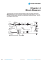
1
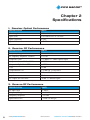
PICO MACOM
Included
PMN-1
Mini-Indoor Optical Node
PMN-1 Owners Manual
Please read this manual thoroughly before use.
Keep this manual handy for future reference.
Visit Our Web-Site www.picomacom.com
Contact Us 858.546.5050
Toll Free 800.421.6511
PICO MACOM
PMN-1 Mini-Indoor Optical Node
OWNERS MANUAL
This manual is intended for use by purchasers of Pico Macom PMN-1 Mini-Indoor Optical Node(s) and their
qualified technicians. This document is the property of Pico Macom and embodies proprietary subject matter. All
design, manufacture, reproduction, use and sale rights regarding the same are expressly reserved. This manual may
not be reproduced without written consent from Pico Macom. All copyright, patent and trade secrets for this manual,
the product, and its included software are expressly reserved by Pico Macom.
SAFETY CONSIDERATIONS
CAUTION
RISK OF ELECTRICAL SHOCK
Do Not Open
Avis – Risqué de choc electrique Ne Pas Ouvrir
For user safety, one or more of the caution labels shown here may be affixed to the side or rear panels of this equipment. The significance of the two symbols enclosed by triangles is described below.
This symbol means that dangerous voltages are present within the equipment. These
voltages are not insulated and may be of sufficient strength to cause serious bodily
injury if touched. This symbol may also appear on schematics.
This symbol calls attention to a critical procedure or means that refer you to the instruction manual for operating or service information. Only qualified service personnel are
to install or service the equipment. This symbol may also appear in text and on schematics.
WARNING: To reduce the risk of fire or electrical shock, do not expose this equipment to
rain or moisture.
2
www.picomacom.com
Owners Manual
CONTACT US TOLL FREE 800-421-6511
PICO MACOM
IMPORTANT SAFEGUARDS
Pico Macom strongly advises you to read and understand the following safety instructions prior to installing and
operating this equipment.
•
Read These Instructions First. All safety and operating instructions should be read before installing or operating this equipment. Safety and operating instructions should be retained for future reference.
•
Retain This Instruction Manual Safety and operating instructions should be retained for future reference.
•
Heed Warnings All warnings on the equipment and in this Owner’s Manual should be adhered to.
•
Ventilation Do not block or cover openings in this equipment. These are provided for ventilation and protection from overheating. Maximum operating ambient temperature is 40°C.
•
Power Sources Operate this equipment only from the type of power source indicated on the rear panel.
•
Grounding or Polarization This equipment may be equipped with a polarized AC line plug (a plug having
one blade wider than the other or a different shape.). This plug will fit into the power outlet only one way.
This is a safety feature. If you are unable to insert the plug into the outlet, try reversing the plug. If the plug
still does not fit, contact your electrician to replace your obsolete outlet. Do not defeat the safety purpose of
a polarized plug.
•
Servicing Refer all servicing to qualified personnel. Opening or removing covers may expose dangerous voltages. When replacement parts are required, make sure the service technician uses only replacement parts
recommended by Pico Macom. Unauthorized substitutions may result in fire, electric shock, or improper operation of the unit.
•
Cleaning Unplug the unit from the AC power outlet before cleaning. Do not use liquid or aerosol
cleaners.
•
Lightning. For added protection during a lightning storm or when the equipment is left unattended or unused
for long periods, unplug it from the power outlet and disconnect the cables between the equipment and the
antenna subsystem. These precautions will prevent damage to the equipment that could be caused by lightning strikes or power line surges.
•
NOTE TO CATV SYSTEM INSTALLERS: This reminder is provided to call your attention to NEC Articles 81021, 820-22, and 820-40 that provide guidelines for proper grounding. In particular, these articles specify that
the cable ground shall be connected to the building grounding system, as close to the point of cable entry as
practical.
•
Optical Output Safety, General. 1310nm Optical Transmitter units may emit harmful invisible laser radiation. These products may emit harmful laser radiation if powered on and the case is opened or the beam path
is exposed.
CONTACT US 858.546.5050
Owners Manual
www.picomacom.com
3
PICO MACOM
Laser Safety Information:
The PMN-1 Mini-Indoor Optical Node Transmitter modules are classified as Class 1M per IEC/EN 60825-1/A2:2001. This
product complies with FDA/CDRH, 21 CFR 1040.10 and 1040.11 except for deviations pursuant to Laser Notice No. 50
dated 26 July, 2001.
Viewing the laser output with certain optical instruments (for example, eye loupes, magnifiers and microscopes) within a
distance of 100 mm may pose an eye hazard. Laser power up to 20 mW at 1310 nm could be accessible if optical connector is open or fiber is broken. Lasers are on (powered) when ever the DLC chassis is powered
CAUTION: Use of controls, adjustments, and procedures other than those specified herein may result in hazardous laser radiation exposure.
4
www.picomacom.com
Owners Manual
CONTACT US TOLL FREE 800-421-6511
PICO MACOM
TABLE OF CONTENTS
Chapter 1 Introduction......................................................................................................................................... 6.............
1. Introducing the Pico Macom PMN-1 Mini -Indoor Optical Node.............................................................. 6-7
2. Features...................................................................................................................................................... 7
Chapter 2 Specifications....................................................................................................................................... 8
1. Receiver Optical Performance.................................................................................................................... 8
2. Receiver RF Performance .......................................................................................................................... 8
3. Reverse RF Performance............................................................................................................................. 8
4. Reverse Optical Performance..................................................................................................................... 9
5. General...................................................................................................................................................... 9
Chapter 3 Installation and Operation................................................................................................................... 10
1. Unpacking the Unit.................................................................................................................................... 10
2.Before Mounting ....................................................................................................................................... 10
3. Mounting................................................................................................................................................... 10
3.1 Spacing and Cooling................................................................................................................................. 10
4. Making Connections.................................................................................................................................. 11
4.1 Power Adapter Connection and Initial Power Up........................................................................................ 11
4.2 Forward Fiber Connection.......................................................................................................................... 12-13
4.3
Cox Connection......................................................................................................................................... 13
4.4 Return Optical Connection........................................................................................................................ 14
5. Maintenance.............................................................................................................................................. 15
Chapter 4 Block Diagram ..................................................................................................................................... 16
Warranty............................................................................................................................................................... 17
CONTACT US 858.546.5050
Owners Manual
www.picomacom.com
5
PICO MACOM
Chapter 1
Introduction
1. Introducing the PMN-1 Mini-Indoor Optical Node
The PMN-1 is a two way optical node with a downstream (forward) signal path and a return signal
path. The downstream signal path includes an optical receiver followed by RF circuitry to extract
and amplify the signal from the optical receiver into a coax cable connector. The return (reverse)
signal path accepts signals from the coax in the 5-42 MHz range and diplexes these signals into
the return laser transmitter. The PMN-1 is an ideal platform for delivering video (analog NTSC
channels or digital QAM channels or a mixture of both) as well as high-speed data services over
today’s advanced hybrid fiber/coax (HFC) networks. The small size makes it ideal for installations
serving apartment blocks, corporate campus buildings or similar where there is an indoor location and nearby AC power. The low cost allows fiber deep dedicated node-to-customer-solutions
where high bandwidth is dedicated to a commercial user or situations where coax noise ingress
would be a problem. Despite its small size, the PMN-1 includes superior proven technologies in
both RF amplifier and optical components to provide the full complement of functions required by
advanced networks.
The PMN-1 receiver accepts one single mode fiber with a SC/APC connector with optical signals
in the 1290-1600 nm wavelength range, making the PMN-1 suitable for common optical network
systems. The forward signal may include a RF signals from 53 to 1000 MHz, allowing for future
bandwidth expansion or for installations such as corporate sites that need to carry today’s broadband spectrum of 54 to 860 MHz and additional channels for that particular site’s needs in narrowcast channels positioned above 860 MHz. A LED lights when an optical signal is present for
your use as a simple monitor. A test point is provided to monitor optical signal level, with 1V/mW
scaling.
6
www.picomacom.com
Owners Manual
CONTACT US TOLL FREE 800-421-6511
PICO MACOM
The PMN-1 RF amplifier uses GaAs technology to provide 25 dBmV to the RF output port and the
-20dBc output monitoring port with superior return loss, CSO, CTB performance. In an example
apartment application, the PMN-1 and splitters without an additional launch amplifier can provide
up to 64 devices (televisions, modems, set top boxes) with some margin to share for coax loss.
The PMN-1 return transmitter provides a 1310 nm optical signal with 5 to 42 MHz RF bandwidth
at 0 dBm output power. A reverse test port provides RF signals which are -20 dB from the 5~42
MHz signals on the coax connected to the RF Out F-connector. The PMN-1 uses SC/APC connectors for the return path optical signal output. A LED lights when the receiver power is present for
simple monitoring use. A test point is provided to monitor optical signal level, with 1V/mW scaling.
The PMN-1 operates from a 12 to 15 VDC external source. That power may be carried on the RF
output coax into the PMN-1 if a remote powering solution is needed. The typical approach is to
use the 120 or 240 VAC AC power adapter included with the node and supply power directly to
the PWR IN port. The node may be mounted where convenient for fiber and RF coax wiring and
with the power adaptor located at a local wall socket power source. The use of F-connectors on
the PMN-1 and the power adaptor allow the installer to use coax cable, connectors, connector
tools, and retaining clips to make custom installations of the length and routing needed using tools
and components already in hand. The PMN-1 typically uses only 5 watts or less for all functions
The typical installation would be a wall mounting with slots provided on both sides of the node’s
housing for a #8 ~#10 screw and washer; the lightweight makes a two screw installation simple.
This manual details the unit specifications, describes any issues that may be critical to your installation, discusses the operation, and, finally, outlines actions if you have problems with the unit. If
you read and follow the installation and operation chapters, the PMN-1 should provide you years
of simple, reliable operation
2. Features
•
•
•
•
•
•
•
•
•
•
•
•
Complete two-way node in minimum size.
Wall mountable chassis
Forward signal bandwidth of 53 to 1000 MHz.
SC/APC Input and Output for efficient, easy interconnection to your network.
Standard 75-ohm female F-connector for RF forward output/reverse input.
Superior RF connection return loss.
25 dBmV output level drives many downstream devices.
Superior RF signal performance based on GaAs technology.
Powering via local mains power AC using supplied adaptor or via coax carried
power solution.
Low operating power requirement.
LEDs monitor presence of optical signals.
Test points are provided to monitor optical signal levels.
CONTACT US 858.546.5050
Owners Manual
www.picomacom.com
7
PICO MACOM
Chapter 2
Specifications
1. Receiver Optical Performance
SPECIFICATION
LIMITS
Wavelength
Input Level
Input Connector
Optical Return Loss
1290 to 1600 nm
-6 to 2 dBm (0.25 to 1.6 mW)
SC/APC
> 45 dB
2. Receiver RF Performance
SPECIFICATION
LIMITS
Frequency Range
RF Frequency Response (Flatness)
Output RF Level
Composite Second Order (CSO)
Composite Triple Beat (CTB)
53 to 1000 MHz
± 0.5 dB
> 25 dBmV @ -1dBm Optical Input
<-65dBc*
<-67dBc*
CNR
>51dB
Output Return Loss
> 16 dB typ. 53-860 MHz
Connector
Impedance
RF Output Test Port Level
F-Connector, Female
75 ohm
-20 dB ± 1 dB from Input
* Loaded with 78 Analog Channnels, -1dBm Input
3. Reverse RF Performance
SPECIFICATION
RF Input Level
Frequency Range
Frequency Response
Input Return Loss
8
www.picomacom.com
LIMITS
15 dBmV
5 to 42 MHz
< ± 0.5dB
> 16 dB (18 dB typ.)
Owners Manual
CONTACT US TOLL FREE 800-421-6511
PICO MACOM
4. Reverse Optical Performance
SPECIFICATION
Wavelength
Output Level
Input Connector
Optical Return Loss
LIMITS
1310 nm.
0 dBm typ., - 3 to +3 dBm (0.5 to 2 mW)
SC/APC
> 45 dB
5. General
SPECIFICATION
Input Power
LIMITS
12-15 Vdc, 350~400 mA watt typ.
Power Connections
1) Dedicated female F-connector for use with
supplied AC adaptor
2) DC power extraction for female f-connector
RF port for use with power on coax
powering solution.
Temperature Range
-20 to +65°C on chassis base
(+40°C max. recommended)
Relative Humidity (non-condensing)
Altitude
Weight
Size
0 to 95%
0 to 15,000 ft
0.75 lb.
4.4”H x 5.2”W x 1.35”D
CONTACT US 858.546.5050
Owners Manual
www.picomacom.com
9
PICO MACOM
Chapter 3
Installation and Operation
1. Unpacking the Unit
Please inspect the cartons on receipt and note damage to the carton and inspect for possible unit
damage. If damage is found, please contact shipper immediately, before unpacking, to follow that
shipper’s procedure for claims.
Please open the carton and unpack carefully. Locate items such as the owner’s manual and power
cord. Do not connect a unit to power if there is serious mechanical damage to prevent possibly
unsafe conditions.
2. Before Mounting
The PMN-1 Mini-Indoor Optical Node has no internal configuration switches and no internal user
adjustments or controls. To prevent unsafe conditions, please do not open the unit. Opening the
PMN-1 will also void the warranty.
3.Mounting
The PMN-1 chassis is designed for installation on a wall or other suitable flat surface. We recommend an installation plan that puts the PMN-1 chassis near the fiber and coax paths and routing
power as required to that location either using the supplied adaptor or using your own DC coax
powering solution.
The chassis base has two mounting ears, one on the upper right corner near the RF OUT connector and one at the lower left near the REVERSE TP. These semi-rectangular openings (slots) accept
a #10 screw. The base is ½ inch thick; allow sufficient additional screw length to attach the Mininode to the surface securely, typically 1 ¼ inch minimum. Anchors are recommended for drywall
and other soft materials to prevent the screws from pulling out while tightening the F-connectors.
Some supplied power adaptors mount directly onto the wall socket for local AC power Mains;
other adaptors may have detachable Mains power cords and must be positioned on a surface out
of the way of traffic where they are not likely to be bumped and/or kicked.
3.1 Spacing and Cooling
The PMN-1 node is very low power consumption so thermal dissipation is generally not an issue.
The Mini-node will dissipate small amounts of heat into the surface to which it is attached and into
the air. Do not attach to a surface that is heated by other equipment or processes. Do not restrict
the airflow around the chassis by closely covering the unit. Do not position the unit where heat
exhausted from other nearby equipment may adversely affect the unit.
10
www.picomacom.com
Owners Manual
CONTACT US TOLL FREE 800-421-6511
PICO MACOM
4. Making Connections
4.1Power Adaptor Connection and Initial Power Up
If you have, and will use, a 12-15 Vdc power inserter that may be connected to the main RF coax,
either locally or at the distant end of the coax, ignore the remainder of this section. Ensure splitters
and other line elements are “power passing”. The PMN-1 will extract the DC powering from the
coax on the RF OUT port if present and no other power need be connected.
If using the supplied power adaptor, position the adaptor where AC mains power is available and
route cabling to the Mini-node. Ensure the AC Mains powering matches the adaptor rating before
connecting the cabling. Use professional tools to crimp the coax cable terminations; they must
be well crimped to ensure reliable ground connections.
Connect the cable to the PWR IN F-connector in upper left corner of the Mini-node and snug
firmly. If using a torque wrench, tighten to 20 inch-pounds. Do not over-tighten.
Connect the power adaptor to the Mains power and observe the LASER ON LED. It will light if
power is properly supplied.
If the LASER ON led fails to light, check presence and level of DC voltage at power adaptor and
at cable connection to the Mini-node.
CONTACT US 858.546.5050
Owners Manual
www.picomacom.com
11
PICO MACOM
4.2 Forward Fiber Connection
• The fiber with the forward path signal must be terminated with a SC/APC connector or a SC/
APC pigtail must be spliced onto the fiber. The SC/APC connector is a rectangular shaped green connector. Blue color SCUPC connector will fit in the Mini-node socket but do not transfer optical power effectively.
• Ensure that you have a fiber carrying less than 3 dBm power level before connecting to the Mini-node. Excessive power may damage the receiver. We recommend checking with an
optical power meter with SC/ACP connection. If above 3 dBm, use an external optical
attenuator (SC/APC female-male type) is needed to bring the level to approximately 0 dBm.
• When ready to make the optical connection, remove and retain the plug in the RCVR optical connector in the lower right corner.
• Prepare the fiber’s connector by cleaning the optical tip. An example cleaner is shown be
low and is used by stroking the tip in one direction only on the cleaning material. Isopropyl alcohol and lint-less cleaning wipes are also suitable. Do not use cotton cloth or swab due to lint. Failure to clean the fiber cables inserted into the Mini-node will cause dirt to
accumulate in the PMN-1 connector. This will decrease received optical power and degrade RF output.
• Hold the SC/APC fiber connector near the Mini-node bulkhead connector and align it with the bulk head connector. Note that one long side of the SC/APC fiber connector has an alignment rib or pin that matches with the slot in the bulkhead connector. Insert the fiber connector into the Mini-node bulk head connector until it seats; the alignment rib should near the end of the slot and the fiber connector aligned squarely with the bulkhead
connector.
• Clean the fiber’s connector each time it is reinserted into the Mini-node
FAILURE TO CLEAN THE FIBER CABLES BEFORE INSERTION INTO THE MINI-NODE IS CONSIDERED ABUSE
AND REPAIRS DUE TO DIRTY CONNECTORS ARE NOT COVERED UNDER WARRANTY.
12
www.picomacom.com
Owners Manual
CONTACT US TOLL FREE 800-421-6511
PICO MACOM
Example of a fiber cable cleaner
(source: Fiber Instrument Sales, www.fiberinstrumentsales.com).
• If optical power is present on the fiber, the OPTICAL POWER LED will be on.
• Check received optical power by using a voltmeter between the chassis and the
OPTICAL LEVEL test point near the OPTICAL POWER LED.
• The scale is 1 V/mW, so the target input should be 1 V. • If the voltage measures more than 2V, the optical input power is more than 2mW (3dBm).
• If the voltage measures less then 0.25V, it means the optical input power is less than 0.25mW (-6dBm).
4.3 Coax Connection
At this point, you may connect a coax cable to the RF OUT port and then to the local coax distribution system (splitters, combiners, amplifiers, etc.) to provide this output to the end user.
You may wish to test the output on a local television as a monitor initially before connecting to
the distribution system but you will have to use the RF TEST port which is 20 dB lower than the
RF OUT or use 20-25 dB attenuation between the RF OUT and the television. (Many televisions
expect +5dBmV as the highest signal level they will receive, so the 25 dBmV output must be
reduced.) When finished with testing the RF OUT port signal, remove any undesired attenuation
and connect this port to the distribution system.
CONTACT US 858.546.5050
Owners Manual
www.picomacom.com
13
PICO MACOM
4.4 Return Optical Connection
You may omit connecting a return path fiber and the Mini-Node will operate satisfactorily as a
one-way forward-only (downstream only) node. Assuming you wish two-way (forward and return)
operation, continue as follows:
•
The fiber with the return path signal must be terminated with a SC/APC connector or a SC/
APC pigtail must be spliced onto the fiber. The SC/APC connector is a rectangular shaped green connector. Blue color SC/UPC connector will fit in the Mini-node socket but do not transfer optical power effectively and may damage the PMN-1 node.
• When ready to make the optical connection, remove and retain the plug in the LASER OUT optical bulkhead connector near the edge of the node. Retain these plugs and reinstall when fiber connectors are not installed to maintain cleanliness of the optical bulkhead connectors.
•
Prepare the fiber’s connector by cleaning the optical tip. An example cleaner is shown above and is used by stroking the tip in one direction only on the cleaning material. Isopropyl
alcohol and lint-less cleaning wipes (Kimwipes) are also suitable. Do not use cotton cloth or swab due to lint. Failure to clean the fiber cables inserted into the Mini-node will cause dirt to accumulate in the PMN-1 connector. This will decrease transmitted optical power and degrade RF output at the distant receiver.
• Clean the fiber’s connector each time it is re-inserted into the Mini-node.
•
Hold the SC/APC fiber connector near the Mini-node bulkhead connector and align it with the bulkhead connector. Note that one long side of the SC/APC fiber connector has an alignment rib or pin that matches with the slot in the bulkhead connector. Insert the fiber
connector into the Mini-node bulkhead connector until it seats; the alignment rib should near the end of the slot and the fiber connector aligned squarely with the bulkhead connector.
• Confirm that the LASER ON LED is lighted as a general check.
• Check transmitted optical power if desired by using a voltmeter between the chassis and the LASER POWER test point near the LASER ON LED.
• The scale is 1 V/mW, so the target input should be 1 Vdc.
If the optical output level is not at or near the target level of 1 mW (1 Vdc), check the REVERSE TP level with RF tools (spectrum analyzer or power meter). It should be 15 mV; if not adjust the distribution system sources to bring the input to the target
• If the voltage measures more than 2Vdc, the optical input power is more than 2mW (3dBm), i.e., offscale high.
• If the voltage measures less then 0.25Vdc, it means the op-tical input power is less than 0.25mW (-6dBm), i.e., off-scale low.
14
www.picomacom.com
Owners Manual
CONTACT US TOLL FREE 800-421-6511
PICO MACOM
5.Maintenance
The PMN-1 node contains no internal user adjustments.
The most likely cause of decreased performance that may be addressed by users is contamination
in the SC/APC connector(s). The optical fiber connectors may be contaminated by the slightest
touch to human skin or other apparently clean surfaces. This contamination is transferred in to
the bulkhead connector and remains when the fiber connector is removed. Over time, this will
cause decreased and intermittent output levels. Users may correct this condition as follows using
commonly available fiber cleaner kits. One possible source is www.fiberinstrumentsales.com.
1. Remove fiber connector from the SC/APC bulkhead connector on the Mini-node.
2. Clean bulkhead connector using standard fiber cleaning tools such as Optipop 2.5mm stick cleaner. Slide stick into the bulkhead and scrub contamination of the bulkhead. In the absence of commercial cleaning tools, a pipecleaner and isopropyl alcohol may be used. A less effective solution is to use canned (clean) air with nozzle to blow contami
nation out of the bulkhead.
3.
Clean the connector plug and insert it into the bulkhead connector if a fiber connector is not to be used immediately. Or, clean the fiber connector using handheld fiber connec-
tor cleaner (as shown earlier in this manual) and insert directly into the bulkhead connector until fully seated.
CONTACT US 858.546.5050
Owners Manual
www.picomacom.com
15
PICO MACOM
Chapter 4
Block Diagram
The diagram below is for general information purposes to allow user to better understand the
PMN-1 node operation. There are no internal user adjustments or repairs possible. The ATT and
EQ shown in the block diagram are factory tuning adjustments and fixed at the factory. These are
not available for users to change.
FIBER IN
O.RE
AMP1
ATT1
EQ
TEST-20dB
AMP2
H
OPT. POWER
1V/mW
FIBER OUT
RF OUT
L
DISPLY
REV.TRANSMITTER
REV AMPLIFIER
POWER
DC-12V
TEST-20dB
LEASER POWER
1V/mW
16
www.picomacom.com
DISPLY
Owners Manual
CONTACT US TOLL FREE 800-421-6511
PICO MACOM
Warranty
Limited Warranty
1
1
1
Pico Macom warrants to the original purchaser that all of its new products are of sound design, quality materials and workmanship at the time of manufacture and will be free from related defects for one year from
the original purchase date. Pico Macom will repair or, at its discretion, replace without cost to the original
purchaser, the product which, upon inspection by Pico Macom, appears to be defective or not conforming
to factory specifications. Pico Macom will cover the cost of parts, labor, and return freight from factory.
Warranty Limitations
This warranty excludes coverage of damage or inoperability resulting from (1) use or installation other than in strict
accordance with Pico Macom’s written instructions, (2) disassembly or repair by someone other than Pico Macom
or a Pico Macom authorized repair center, (3) misuse, misapplication or abuse, (4) alteration, (5) lack of reasonable
care or (6) wind, ice, snow, rain, lightning, power surges, excessive heat, or any other weather conditions or acts
of God. Pico Macom’s warranty with respect to third-party proprietary sub-assembly modules and/or private-label
products are limited to the duration and terms of third-party vendors’ warranty. Pico Macom shall in no event and
under no circumstances be liable or responsible for any consequential, indirect, incidental, punitive, direct or special
damages based upon breach of warranty, breach of contract, negligence, strict tort liability or otherwise or any other
legal theory, arising directly or indirectly from the sale, use, installation or failure of any product acquired by buyer
from Pico Macom. This limited warranty extends to the original purchaser. Pico Macom reserves the right to modify
or discontinue this warranty at Pico Macom’s sole discretion without notification. No other warrantees are expressed
or implied.
Damage or Shortage Claims
Our shipping staff carefully packs and ships your orders in compliance with common carriers’ requirements. Please
make note of any obvious damage or shortage on the freight bill or carrier’s receipt next to your signature. The carrier’s agent must too sign acknowledging the loss. Failure to do so may result in the carrier’s refusal to honor the claim.
Please open your order immediately upon receipt to check for concealed damage and compare the packing list to the
items shipped. If damaged, keep the original shipping cartons for possible inspection by the carrier. You must report
claims for loss or damage within 3 days of delivery, while claims for erroneous charges or price corrections must be
presented within 30 days of invoice date.
Returning Shipped Items
To return any shipped items, including those shipped for warranty repairs or credit, call our Customer Service desk
to request a Return Merchandise Authorization (RMA) number. Please reference the original invoice number and
purchase date, and product serial number (if any). Be certain to mark the RMA number on the package boldly and
legibly. Unless we specify a different carrier, please ship your returned items to us via UPS freight prepaid and fully
insured. If returned for credit, we will promptly process your request upon receipt of your return order.
Our Return Policy: Your Satisfaction Guaranteed
Our goal is your complete satisfaction. If for any reason, our products were not quite what you anticipated, simply
call your customer service rep and we will be happy to assist you in replacing or returning the order. You may return
current, non-discontinued items for full credit for up to 30 days from invoice date. Our requirements are simple:
Excepting defective items, the products must be returned in their original packaging and in re-salable condition.
Restocking fees may otherwise apply beyond this period or if products are not returned in their original condition.
Please contact your customer service rep for more information.
*One-year warranty if sold outside U.S.A.
CONTACT US 858.546.5050
Owners Manual
www.picomacom.com
17
PICO MACOM
6260 Sequence Drive, San Diego California 92121
Sales: 800-421-6511 Phone: 858-546-5050 Fax: 858-546-5051
[email protected] www.picomacom.com