1
ATS Installation Setup and Maintenance P/N SG07230018 REVISION D Des Moines, IA (800) 333‐7411 Burnsville, MN (800) 289‐1330 Mundelein, IL (888) 905‐7411 THIS DRAWING IS COPYRIGHTED AND IS THE PROPERTY OF CERTIFIED POWER INC. Bridgeton, MO (800) 999‐7411 Perrysburg, OH (800) 374‐7411 Freedom ATS Users Manual: SG07230018 User Manual Freedom ATS FREEDOM ATS USERS GUIDE MOBILE DATA COLLECTION DEVICE PART# SG07040073(Wi‐Fi, GPS Receiver.) PART# SG07040074(non‐Wi‐Fi, no GPS Receiver) PART# SG07040078(non‐Wi‐Fi, GPS Receiver.) PART# SG07040087(non‐Wi‐Fi, No GPS Receiver, No Sd Card) Revision history REVISION 1 A B C D DATE 3/27/2009 10/30/2009 2/3/2010 8/16/2010 8/28/2012 DESCRIPTION FIRST DRAFT RELEASE
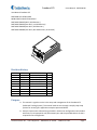
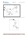
PROD. UPDATES PROD. UPDATES PROD. UPDATES PROD. UPDATES CCN 593 Purpose A. This manual is a guide to assist in the setup and management of the Freedom ATS (Advanced Tracking System). This manual leads the user through a step‐by‐step setup process for several given application examples presented below. B. Setup is simple and is achieved using the built in web server configuration tool included with each unit. A laptop with a 10/100 network port and the provided cable is all that is required for fast configuration. Certified Power Inc. 970 Campus Dr. Mundelein, Il 60060 1‐888‐516‐5245 Page 2 Freedom ATS Users Manual: SG07230018 Contents Revision history ............................................................................................................................................. 2 Purpose ......................................................................................................................................................... 2 Product Description ...................................................................................................................................... 5 Supported Applications ............................................................................................................................. 7 Freedom ATS (User) panel description ..................................................................................................... 9 Installation of Equipment ........................................................................................................................... 11 Mounting dimensions ................................................................................................................................. 12 Wiring and Cable Layout ............................................................................................................................. 13 Optional Wiring Switches and Output Devices/Main Power ...................................................................... 13 Setup and Configuration ............................................................................................................................. 14 Accessing the Web Server ....................................................................................................................... 14 Admin Access Login ................................................................................................................................. 16 Main menus ............................................................................................................................................ 16 Applying Changes .................................................................................................................................... 18 Save a Configuration File ........................................................................................................................ 19 Removing the SD card ............................................................................................................................. 19 View a saved file ..................................................................................................................................... 20 Delete a saved file ................................................................................................................................... 20 Restoring a saved file .............................................................................................................................. 20 Setting Time and Date ............................................................................................................................. 21 Manual Data Transfer Application Guide (Removable Data storage) ........................................................ 22 Equipment required. ............................................................................................................................... 22 Summary of hardware installation steps ................................................................................................ 22 Configure an Application using Manual Data transfer ............................................................................ 23 General Configuration & Setup ............................................................................................................... 23 The Server Interface ................................................................................................................................ 26 Maintenance. .......................................................................................................................................... 27 Cellular Modem or LMU Application Guide (Cellular data transfer): ......................................................... 28 Equipment required. ............................................................................................................................... 29 Summary of hardware installation steps ................................................................................................ 29 Configure a Cellular or LMU Application ................................................................................................ 29 Certified Power Inc. 970 Campus Dr. Mundelein, Il 60060 1‐888‐516‐5245 Page 3 Freedom ATS Users Manual: SG07230018 General Configuration & Setup ............................................................................................................... 29 The Server Interface ................................................................................................................................ 33 Modem Configuration and setup ............................................................................................................ 35 Maintenance ........................................................................................................................................... 35 Drive‐by Download Application Guide (Wi‐Fi) ............................................................................................ 36 Equipment required. ............................................................................................................................... 36 Summary of hardware installation steps ................................................................................................ 36 Configure a Wi‐Fi Drive‐by Application ................................................................................................... 37 General Configuration & Setup ............................................................................................................... 37 The Server Interface ................................................................................................................................ 40 Wireless Configuration. .......................................................................................................................... 42 Network Configuration ........................................................................................................................... 43 Maintenance ........................................................................................................................................... 43 ATS mini ...................................................................................................................................................... 44 Equipment required. ............................................................................................................................... 44 Summary of hardware installation steps ................................................................................................ 44 Configure an Application using the ATS Mini .......................................................................................... 45 General Configuration & Setup ............................................................................................................... 45 The Server Interface ................................................................................................................................ 48 Input Configuration ..................................................................................................................................... 49 General Setup of inputs .......................................................................................................................... 49 Counter Input Configuration ................................................................................................................... 51 Counter Input Calibration (Viewing Counts using the built in Pulse Counter) ....................................... 51 Diagnostic tools/Troubleshooting Assistance ............................................................................................. 52 Diagnostic LED’s. ..................................................................................................................................... 52 GPS Viewer .............................................................................................................................................. 53 Event/Error log ........................................................................................................................................ 54 Modem status ......................................................................................................................................... 55 Updating firmware/Loading defaults/Restoring your settings ................................................................... 56 Deleting a Configuration (Restoring defaults) ............................................................................................ 58 Wi‐Fi Setup & Security (Glossary of terms) ................................................................................................. 59 Certified Power Inc. 970 Campus Dr. Mundelein, Il 60060 1‐888‐516‐5245 Page 4 Freedom ATS Users Manual: SG07230018 What’s included A. The illustration below details the optional and included hardware with each Freedom ATS unit. (2X) 2 dBi DI-POLE
ANNTENNA
STANDARD POWER
HARNESS
P# SG07050880
GPS WINDOW
MOUNT ANTENNA
P# SG07040076
I/O HARNESS
6-WIRE(Optional)
P# SG07050879
8-WIRE
P# SG07050878
SD MEMORY CARD
PART# SG07040081
DD
yy
yy
yy
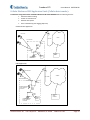
Product Description The Freedom ATS is a simple to apply Mobile Data Management & Collection Device. The primary advantage of the ATS is easy installation and setup. A Cellular Service is not required for 2 out of 4 typical ATS Setups shown here. Out of the Box standard features include a removable SD memory card for seasonal data collection, or built in on‐
board Wi‐Fi (Drive‐by‐Download). The standard unit also requires NO additional software to begin management with its built in web configuration tool, setup and maintenance couldn’t be more convenient. If the ATS is on a network or connected to your laptop using the provided cables, all setup and configuration can be done with any PC running a web browser such as Internet Explorer™, Firefox™, or Opera™. The WLAN (Wi‐Fi) transceiver includes all the latest authentication methods and also the latest levels of 802.11 A/B/G/I, encryption. The Freedom ATS is compatible with the model GL400, Freedom 2 or ACS spreader control units. The ATS can be used with any other Application that utilizes a compliant standard RS‐232 serial port. The ATS can be used for many applications that utilize its standard features including asset tracking or remote data acquisition, storage and transmission. GPS Receiver (optional), The GPS signal contains GMT time, latitude and longitudinal data and other geometric data used to calculate velocity and altitude. Snap‐shots of current GPS data along with a time stamp and any other data such as from a Salt Spreader controller are stored together in sequential records. If using the GPS receiver the real‐time clock is based on GMT (or UTC) time received from the satellite. If no GPS receiver is installed then data is time stamped based on the set time of the internal real‐time clock value. Wi‐Fi, (Wireless LAN) (optional), This Wireless IP Gateway option is one of two wireless options used for data transfer and equipment configuration and maintenance. Wireless LAN is a good cost economical alternative to a Cellular data or the complications of using a Digital radio network. The latest levels of authentication and encryption are available for the Wireless LAN (Wi‐Fi). The downside of Wireless LAN offers no real‐time Data transfer such as with Cellular and has limited signal range (120 to 900ft.) Certified Power Inc. 970 Campus Dr. Mundelein, Il 60060 1‐888‐516‐5245 Page 5 Freedom ATS Users Manual: SG07230018 10/100 Ethernet, This is a wired LAN port. This port is typically used for web services especially during initial setup of the ATS device when it’s fresh out of the box. Web based configuration and troubleshooting are done using this connection. Web services can be accessed over the Wi‐Fi port as well, once the port configuration has been setup. The wired 10/100 Ethernet port is programmed from the factory with a static IP address of 192.168.11.120. Use your computer and the provided cross‐over network cable P#SG07050754 or attach the unit to your network with any standard network cable. Use your PC’s Internet Explorer™, Mozilla Firefox™ or Opera™ internet browser to complete setup and configuration. See the section about accessing the web server below. Digital inputs (Not used on ATSmini), ANY battery level or switch to ground signal can be wired into the digital inputs. The inputs are rated for voltages from ground level to 28volts. The inputs also have integrated noise immunity and surge protection. Inputs can be configured to activate by switching to ground or switching to power. Use the on‐board web configuration tool to program input options. Some application examples are listed below. Inputs 1‐8 can be configured as counters up to 300 hertz. Input 8 can be used as a High Speed counter to 5 Khz. Plow position switch 3‐wire Proximity switch Body Up detect switch Way‐point input switch Hall /Motor Sensor input Battery level outputs (4) (Not used on ATSmini), Hi‐level output drive capability. These outputs can switch peak loads up to 6 amps continuous. These outputs can be used for basic I/O requirements; Reverse polarity, thermal, and short circuit protection make these outputs useable for any resistive or inductive load applications. Modem serial port, This physical DB‐9 connector style RS‐232 serial port is intended for connection of RS‐232 cellular modem using RS‐232 level compliant serial communication. The port contains all control lines available for full modem control. Baud rates and all setup parameters are accessible through the web based configuration tool. Real‐time cellular data is transmitted out of this port when a cellular modem is attached. Spreader Serial port, This physical DB‐9 connector style RS‐232 serial port is intended for connection to Material Spreaders or other on and off‐road equipment controllers with a serial port. This port is a 3‐wire port TX,RX, and Ground connection. This data connection links the Salt spreader or ON and Off road equipment to the ATS system and allows materials data to be captured and stored on the ATS unit for retrieval through any installation option defined in this document. Road‐Watch SS™ (RS‐485) (Not used on ATSmini), This half‐duplex RS‐485 serial ports default usage has it configured for the Commercial Vehicle Systems (Sprague devices) Road‐Watch™ communications. The port auto detects the Road‐Watch SS sensor when it is plugged in. Note: This port is Not active when the spreader interface is configured for a Freedom ACS. SD Memory card (Not used on ATSmini), The Industrial rated removable FAT file system drive is Microsoft Windows™ compatible and is the default storage location for all data records for your application. It is recommended that the SD memory card be installed for most applications. Those applications include manual data transfer, real‐time cellular data transfer and Drive‐by‐download. Limited data collection can be done without the SD card installed but the file size is limited and is not a suitable substitute for the SD card. Certified Power Inc. 970 Campus Dr. Mundelein, Il 60060 1‐888‐516‐5245 Page 6 Freedom ATS Users Manual: SG07230018 Supported Applications Below are some rudimentary diagrams of some supported applications. This manual is intended to help the user setup or make adjustments to their application. It is likely your application could use features that encompass multiple examples below. Manual Data Transfer Application (Removable data storage SD card) LAPTOP OR
DESKTOP
GPS SATELLITES
SD
USB TO SD CARD
ADAPTOR
VEHICLE EQUIPMENT
GPS ANTENNA
FREEDOM ATS
SERIAL
CABLE
SALT
SPREADER
CONTROL
I/O DEVICES: SWITCHES,
RELAYS, HYDRAULIC
VALVE COILS
Cellular Modem Application (Real‐Time Cellular Data transfer) GPS SATELLITES
INTERNET
CELL TOWER
VEHICLE EQUIPMENT
CELL
ANTENNA
CELLULAR
MODEM
SERIAL
CABLE
GPS ANTENNA
FREEDOM ATS
SERIAL
CABLE
I/O DEVICES: SWITCHES,
RELAYS, HYDRAULIC
VALVE COILS
SALT
SPREADER
CONTROL
COMPUTER
CLIENT
DATABASE
Certified Power Inc. 970 Campus Dr. Mundelein, Il 60060 1‐888‐516‐5245 Page 7 Freedom ATS Users Manual: SG07230018 Drive‐by Download Application (Wi‐Fi) CENTRAL OFFICE
WI-FI ANTENNAS
GPS SATELLITES
LIMITED RANGE
ACCESS POINT
VEHICLE EQUIPMENT
COMPUTER
CLIENT
DATABASE
WI-FI ANTENNAS
GPS ANTENNA
FREEDOM ATS
SERIAL
CABLE
I/O DEVICES: SWITCHES,
RELAYS, HYDRAULIC
VALVE COILS
SALT
SPREADER
CONTROL
The ATSmini, a low Cost Safe and reliable Solution for data collection gateway between Salt Spreaders and LMU or Modem. VEHICLE EQUIPMENT
LMU/MODEM
SERIAL
CABLE
FREEDOM
ATSmini
SERIAL
CABLE
SALT
SPREADER
CONTROL
Certified Power Inc. 970 Campus Dr. Mundelein, Il 60060 1‐888‐516‐5245 Page 8 Freedom ATS Users Manual: SG07230018 Freedom ATS (User) panel description A. WLAN (WIFI). Wireless LAN network connection. The panel connector is SMA MALE (x2) type. B. Wired 10/100. Ethernet network. The wired port is a standard feature on all units. C. System Status LED’s. Standard to all ATS units are status LED’s displaying real‐time diagnostic codes. See diagnostics and troubleshooting section at the end of this manual. D. SD CARD. Standard to ALL ATS units. Removable memory card is used as primary data storage. It is highly recommended this card always be installed into the ATS unit when the ATS unit is powered on. E. GPS Antenna. Attached window mount GPS antenna to this connector. The panel connector is SMA FEMALE type. USER PANEL
WIRED 10/100
WLAN ANTENNA
GPS ANTENNA
NETWORK
(WIFI) PRIMARY WLAN ANTENNA
CONNECTION
(WIFI) SECONDARY
SD MEMORY
CARD
SYSTEM STATUS
LEDS
(WIRED 10/100 NETWORK)
LINK/ACTIVITY LED'S
Certified Power Inc. 970 Campus Dr. Mundelein, Il 60060 1‐888‐516‐5245 Page 9 Freedom ATS Users Manual: SG07230018 Freedom ATS (Interface) panel A. Digital inputs. Attach Toggle switch, Proximity switch, Door pin switch, or Hall Motor Sensor to these 8 inputs. Both Battery and Ground signals are compatible. A BAT+ and Ground is available at the 10‐pin connector. Do not attach the ground to chassis if it can be avoided to prevent extra ground loops. The input current is 10mA. At 13.8volts when pulled to ground and 5mA when configured for switch to power. Configure inputs through the Webpage menu “Input Configuration”. B. Digital outputs. Battery level driven outputs. Drive up to 4 separate loads simultaneously. Short circuit and thermally protected. These can be custom configured for your application. C. Modem serial port (RS‐232). DB‐9, RS‐232 compliant full‐modem control port. D. Spreader serial port (RS‐232). Host type (Male) Db‐9 RS‐232 compliant 3‐wire TX,RX, & Ground. E. Battery and Ground connector. Wire into a minimum 5 amp accessory ignition switched circuit. Attach ground lead to a good chassis ground connection. F. Road‐Watch SS connection. Connect the Sprague devices “Road watch” air and road surface temperature sensor here. Use s Turk M8 6P style connector. Road‐watch sensor part# 849‐0242‐
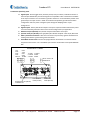
000 INTERFACE PANEL
1-IN1
2-IN2
3-IN3
4-IN4
5-BATT+
6-IN5
7-IN6
8-IN7
9-IN8
10-GND.
10 9 8 7 6
5 4 3 2 1
1-LOAD1
2-LOAD2
3-LOAD3
6 5 4
3 2 1
4-LOAD4
5-GND.
6-GND.
2 1-BATT. SUPPLY IN
1 2-GROUND IN
FULL MODEM
PORT (RS-232)
ROAD-WATCH SS (RS-485)
CONNECTION
SPREADER
PORT (RS-232)
Certified Power Inc. 970 Campus Dr. Mundelein, Il 60060 1‐888‐516‐5245 Page 10 Freedom ATS Users Manual: SG07230018 Installation of Equipment Equipment required. Freedom ATS unit: SG07040073 (With Wi‐Fi and GPS), SG07040074 (No Wi‐Fi and without GPS) or SG07040078 (No Wi‐Fi but with GPS), or SG07040087 (No Wi‐fi, GPS or SD Card installed) ATS Server Software part# SGS00300100003 Optional ATS Database Reporting Software SGS00300100002 Basic tools to mount the ATS device and route and splice the wire harness into the vehicle. Mount the ATS unit 1. Securely mount ATS device inside the vehicles interior cab. The User panel would typically be oriented for easy access to the LED indicators, 10/100 port and SD Card slot. Attach Wiring and cables 2. ‐Attach fused primary Battery and ground wires. 3. ‐Attach serial cables provided to spreader controller. Use the INSTALLATION and WIRING AND CABLE LAYOUT pictorials as a guide. Install GPS antenna (If GPS RCVR installed) 1.‐Properly install the GPS antenna as described in the installation steps below. a.
b.
c.
The sealed weather‐proof GPS antenna has an integral magnet and ideally should be located above the vehicle with a clear view of the sky. Avoid overhead metal objects that will interfere with satellite signals. Avoid mounting areas that have excessive heat, vibration or locations close to other antenna’s or sources of magnetic fields such as electric motors or high current or high voltage wiring such as strobe lights. GPS ANTENNA
GPS ANTENNA
NON-OBSTRUCTED
VIEW OF SKY
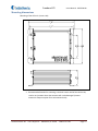
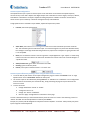
Certified Power Inc. 970 Campus Dr. Mundelein, Il 60060 1‐888‐516‐5245 Page 11 Freedom ATS Users Manual: SG07230018 Mounting dimensions Mounting of the ATS unit. (not to scale)
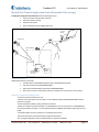
Recommended location for mounting is the back interior wall of the vehicle cab, trunk or any location where the antennas will not be damaged. (remote antenna is always an option for trunk mounted units) Certified Power Inc. 970 Campus Dr. Mundelein, Il 60060 1‐888‐516‐5245 Page 12 Freedom ATS Users Manual: SG07230018 Wiring and Cable Layout 2
1
CHOOSE
COMPATIBLE
CABLE
(SEE ADDEMDUM FOR
TESTED MODEMS)
1
2
GROUND IN.
POWER HARNESS
PART# SG07050880
BATTERY IN.
ROADWATCH PART#
849-0242-000
ATTACH TO 5 AMP
MINIMUM FUSE
PROTECTED
IGNITION CIRCUIT
MULTI-TECH MODEM
HARNESS PART#
SG07050753
CELLULAR MODEM
OR RADIO
ACS SERIAL CABLE
PART# SG07050647
ATTACH TO BARE METAL
EXPOSED CHASSIS
GL400/FREEDOM 2
SERIAL CABLE PART#
SG07050056
GL400 SPREADER
Optional Wiring Switches and Output Devices/Main Power INPUTS SWITCHES AND POSSIBLE USES
OF OUTPUT DEVICES SHOWN.
POWER HARNESS
6 5 4
3 2 1
10 9 8 7 6
5 4 3 2 1
INPUTS
5
6
7
8
9
10
OUTPUTS
2
3
4
OUT-4
1
OUT-3
BATT. SUPPLY
GROUND
IN-8
IN-7
IN-6
IN-5
IN-4
IN-3
IN-2
IN-1
HARNESS PART#
SG07050879
5
6
GROUND
4
GROUND
3
OUT-2
2
OUT-1
1
HARNESS PART#
SG07050878
2
1
IN-8
1
IN-7
IN-6
+ lamp
IN-3
+
IN-5
-
GROUND IN.
IN-4
2
BATTERY IN.
POWER HARNESS
PART# SG07050880
ATTACH TO BARE METAL
EXPOSED CHASSIS. KEEP
GROUND WIRE AS SHORT
AS POSSIBLE
IN-2
solenoid
-
+
3A. AGC FAST
ACT ONLY
+
BUZZER
-
RED
relay
ATTACH TO 5 TO
10 AMP FUSE
PROTECTED
CIRCUIT
Certified Power Inc. 970 Campus Dr. Mundelein, Il 60060 1‐888‐516‐5245 Page 13 Freedom ATS Users Manual: SG07230018 Setup and Configuration
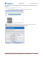
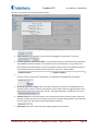
Attach your computer configured with a static IP address to the wired Ethernet connection on the side of the ATS device using the provided cross‐over cable P#SG07050754. LAPTOP OR
DESKTOP
FREEDOM ATS SERVER UNIT
CABLE PART# SG07050754
Accessing the Web Server Connecting for the first time to the ATS configuration utility (Web browser utility) 1.
2.
Apply Power to all devices (Spreader, ATS system, and Spreader control system) The green LINK, and intermittently the yellow ACTIVITY LED’s should become active if there’s a good connection over the Ethernet cable from your laptop to the ATS device. -USER PANELFREEDOM ATS
YELLOW
ACTIVITY
LIGHT
GREEN
LINK LIGHT
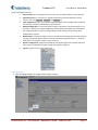
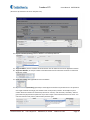
Certified Power Inc. 970 Campus Dr. Mundelein, Il 60060 1‐888‐516‐5245 Page 14 Freedom ATS Users Manual: SG07230018 Open your Internet Browser to gain basic access to the Home Page (Setup and Configuration cont.) 1.
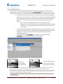
First time users can use their internet browser to navigate to the default static address exactly as shown below in the upper magnified view http://192.168.11.120. 2.
The Home page displays basic information about the ATS system. Product name, Freedom ATS Firmware version, This number tracks what software release currently resides on the device. Internal Db Version, The version of the internal database. This usually changes when the firmware version changes. Build Date, Tells you build/release date of the software running on this system. BSP firmware load date, The last date the rom.bin file was loaded. Application firmware load date, The last time the image.bin file was loaded. Backup firmware load date, The last time the backup.bin file was loaded. IP Address (Ethernet or Wireless), The current IP address assigned to this ATS unit. Ethernet/Wireless MAC Address, A fixed unique address associated with the network port. Up Time, Continuous Run‐Time since last boot. Total Run Time, Total cumulative run time since the last configuration change. Without logging‐in there is access to a few basic menus for diagnostic purposes. Home, Always brings you back to Home page. GPS Viewer, GPS data can be viewed without logging in. Event log, View Event log (Errors and Status messages) Reboot, Reboot the ATS unit. The default factory static IP address to navigate to through your internet browser is 192.168.11.120 and is used for the wired Ethernet port located on the side of the ATS unit. It is recommended to leave this port configured as a static address so it can be easily accessed. 3.
4.
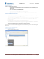
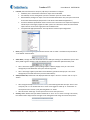
Certified Power Inc. 970 Campus Dr. Mundelein, Il 60060 1‐888‐516‐5245 Page 15 Freedom ATS Users Manual: SG07230018 Admin Access Login 1.
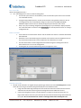
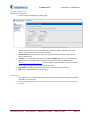
Click on logo to gain access to login dialog box. You must log‐in as Administrator to make configuration changes to the ATS unit. The user name and password are case sensitive and must be entered exactly as shown below. The administrator login name is “CP Service” The password is “847‐573‐3800” Main menus 2.
The HOME menu screen will appear after a successful login. 3.
If you have a problem logging in you will see the “page Access denied”. (see next page) Certified Power Inc. 970 Campus Dr. Mundelein, Il 60060 1‐888‐516‐5245 Page 16 Freedom ATS Users Manual: SG07230018
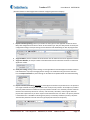
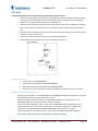
Page Access Denied screen shown after failed login. Menus and sub‐menus (Setup and Configuration cont.) Purpose: The menu tree always appears on the left side of the web page. You can click on any item visible on the tree. The menu seen below is available after successfully logging in as an administrator. When changing items on a particular page be sure to “APPLY” any changes before leaving the page or the changes will be thrown away. Home, Clicking home always brings you back to the Home screen (The first screen viewed after successfully connecting to the ATS web server). GPS Viewer, GPS data can be viewed. Note: ATS must have a GPS installed and configured. Event/(error) Log, If “Verbose” logging is enabled you can view STATUS and ERROR logging here. Reboot, After completing changes on any webpage it is necessary to reboot to have changes take effect. Network Configuration, Change settings relating to the physical setup of network connections (TCP/IP). File Management, View current database files in flash memory or see data records or config files saved to the FAT file system located on the SD memory card. It is also possible to select a new database file (ATSconfig.bin) if one is has been saved. Install Options, The application and hardware setup occurs on this screen. Save Configuration, Creates 2 files including a binary file on the SD memory card that contains all configuration data useful for restoring system configuration on a new or existing ATS unit. The second file is a text file that can be read directly using Microsoft WordPad ™. Menus and sub‐menus continued (on next page) (Setup and Configuration cont.) Certified Power Inc. 970 Campus Dr. Mundelein, Il 60060 1‐888‐516‐5245 Page 17 Freedom ATS Users Manual: SG07230018 (Setup and Configuration cont.)
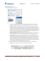
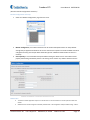
Date and Time, View and change the current time. Auto set if GPS checked in “Install options”. Upload Firmware, If it’s necessary to upgrade the firmware (functional code) then use this screen to select the image.bin, backup.bin and ROM.bin file. Input Configuration, Every system has 8 configurable digital inputs. Configure them in software with Pull‐ups, Pull‐Downs and define their logical function. Modem Configuration, In most cases when a modem is selected as a Physical interface it is not necessary to change your modem configuration because approved modems have already been pre‐configured with the necessary settings withing the ATS. However those settings can be modified when required. Modem Status, The physical modem serial communication hand‐shaking lines can be checked on this page. A good bi‐directional serial line would show all boxes populated with a “1” when the modem port is activated or modem is trying to dial out. Wireless Configuration, Configure the WLAN link, See signal strength of the network and setup basic security or advanced encryption settings if encryption is required. Log‐Out, Log‐out of your current web session Applying Changes 4. After changing variables on a page use the “APPLY” button. Certified Power Inc. 970 Campus Dr. Mundelein, Il 60060 1‐888‐516‐5245 Page 18 Freedom ATS Users Manual: SG07230018 Save a Configuration File (Setup and Configuration cont.) 5. When the system is fully operational and all equipment is setup and working you can use the “SAVE Configuration” menu to save all configuration settings**see note below** into both a binary file and text file location on the SD card. This is especially useful when it’s necessary to set up multiple units in the field. Once a file has been saved on the SD card it is only there for one boot. If the configuration file exists on the card at boot it will replace the current ATS’s onboard configuration with the file on the SD card. The SD card file is then deleted. A new file can be saved at anytime you wish to save the settings. When the file is saved any existing file on the SD Card is over‐
written. Note: To retrieve a configuration file; First save the file using the “Save Configuration” menu. Power down the system. Remove the SD card after removing the Card cover. Using a Card reader on your laptop or desktop copy the files onto your hard drive. It is advisable to keep a copy of the configuration file on your desktop or laptop PC for later retrieval. The file can be used on any ATS unit of the SAME SOFTWARE REVISION to install a configuration. Usually only the truck ID field must be updated when programming subsequent ATS systems. The standard file name is atsconfig.bin. The readable version of the file is called ATSConfig.txt. Open the file to view using Microsoft Wordpad™. Removing the SD card Using your finger nail push the card in to activate the detent ejection of the card. Loosen the screw partially and rotate cover. 1.
2.
Do not use the ACS system for extended amounts of time without the SD card installed. The onboard memory size is limited and typically should not be used for more than a couple days without download to a network drive or On‐board SD Card. Re‐install the SD card by pushing it in until the detent mechanism clicks and resets itself. The card should be flush to the panel surface. If the system is ‘on’; cycle power to the ATS unit so on boot it will find the card. The data written to the on‐board memory is then moved to the SD card where the data continues to accumulate. Note: The ATSmini has no way for configuration files to be saved or restored. Configuration must manually entered for each Setup because of no SD Card. Certified Power Inc. 970 Campus Dr. Mundelein, Il 60060 1‐888‐516‐5245 Page 19 Freedom ATS Users Manual: SG07230018 View a saved file (Setup and Configuration cont.) 6. Use “File Management” screen to view and manage files. The FAT file system refers to the SD Memory card. The native file system refers to the on‐board non‐removable memory. If programming multiple systems, remove the SD card after saving the file and insert it into an un‐configured ATS unit to automatically configure an ATS unit OF THE SAME SOFTWARE REVISION. Replace the SD card in an already configured system with one that is blank. Keep a copy of your working configuration (ATSConfig.bin) on your desktop or laptop computer. Use an SD card reader to retrieve a saved AtsConfig.bin file. See the previous section on “Saving a configuration file”. Delete a saved file If the Check box is selected under “delete” and the “Delete Files” button is used the selected files will be deleted. Because the card is formatted using the FAT32 file system the files can be managed the same as any external drive when the SD card is installed into your Windows PC or Laptop. The files shown below are the Configuration files and Status log files. Deleting these will not affect the ATS unit or it’s current configuration. A Holding.bin file Cannot be deleted using the file management screen Restoring a saved file 7. Any ATS can be restored to its original setup by powering‐up the ATS unit with an ATSconfig.bin file located on the SD card as long as the that file was generated by the same software Version. Using a SD card reader drag and drop a file onto the SD card. Place the card into the ATS card slot and Power the ATS ‘ON’ If the file is good the configuration will be loaded into the unit. Use the file management screen to confirm the file is no longer on the SD card. If the file is no longer listed under the FAT file system then the file and all the associated settings were loaded into the system. Be sure the SD Card ‘Lock’ switch is in the Off position when installing the card. Certified Power Inc. 970 Campus Dr. Mundelein, Il 60060 1‐888‐516‐5245 Page 20 Freedom ATS Users Manual: SG07230018 Setting Time and Date (Setup and Configuration cont.) Click on the “Date and Time” menu item Daylight Savings Time In/Out, The latest version of ATS firmware (version 7) automatically accounts for Daylight Savings. Older version of software require you to select it if it’s needed. Local Date, Local Date is always updated from recent data received from the GPS. While the satellite signal is being received then the date/time is automatically set by Satellite. The fields will be grayed out and cannot be changed. Selecting your proper time zone becomes important (see below “Time Zone”). If no GPS receiver is installed or a Satellite signal is not available, then the time and date is maintained locally by the real‐time clock and on‐board lithium battery back‐up. If no GPS is installed the Time and Date will need to be set manually. GMT Date, GMT Time of day A reference to GMT Greenwich (London) Mean Time. The standard time by which all data is time and date stamped. GMT time comes from the GPS if installed. Local Time of Day, Local Time of Day always updated from recent data received from the GPS satellite. While the satellite signal is being received then the time is automatically set by Satellite. The fields will be grayed out and cannot be changed. Selecting your proper time zone becomes important (see below). If no GPS receiver is installed or a Satellite signal is not available, then the time and date is maintained locally by the real‐time clock and on‐board lithium battery back‐up. If no GPS is installed the Time and Date will need to be set manually. Note: The GPS antenna must have an unobstructed view of the sky to receive a satellite signal. Time Zone, Enter your time zone to set the correct offset from GMT time.
Certified Power Inc. 970 Campus Dr. Mundelein, Il 60060 1‐888‐516‐5245 Page 21 Freedom ATS Users Manual: SG07230018 Manual Data Transfer Application Guide (Removable Data storage) Freedom ATS using basic data collection with the following features: Time and location stamped data collection. GPS based vehicle tracking Material data capture Driver initiated Way‐point logging (Optional) LAPTOP OR
DESKTOP
GPS SATELLITES
SD
USB TO SD CARD
ADAPTOR
VEHICLE EQUIPMENT
GPS ANTENNA
FREEDOM ATS
SERIAL
CABLE
I/O DEVICES: SWITCHES,
RELAYS, HYDRAULIC
VALVE COILS
SALT
SPREADER
CONTROL
Equipment required. (Manual Data transfer continued) Freedom ATS unit SG07040074 (without GPS) or SG07040078 (with GPS) ATS Server Software part# SGS00300100003 Optional ATS Database Reporting Software SGS00300100002 Basic tools to mount the ATS device and route and splice the wire harness into the vehicle. Summary of hardware installation steps ‐Install the ATS Server Software on a PC. ‐Securely mount ATS device into the vehicle. Use the INSTALLATION and WIRING AND CABLE LAYOUT pictorials as a guide. ‐Attach fused primary Battery and ground wires to devices ‐Attach serial cable to spreader controller. The SG07050647 is for use with the ACS, or SG07050056 for use with the GL400 or freedom 2. Use the INSTALLATION and WIRING AND CABLE LAYOUT pictorials as a guide. ‐Install GPS window antenna. (If device is has onboard GPS receiver) ‐Attach wired Ethernet connection between laptop and ATS device ‐Run through configuration steps as detailed below to complete installation Certified Power Inc. 970 Campus Dr. Mundelein, Il 60060 1‐888‐516‐5245 Page 22 Freedom ATS Users Manual: SG07230018 Use your browser to connect to the Web configuration tool as described in the previous section “Accessing the Web Server”. Configure an Application using Manual Data transfer General Configuration & Setup 1. Click on “Install Options”. The application and hardware setup occurs on this screen. Note: Select Pop‐up help to enable the help dialog box as you mouse over items. It is highly recommended to enable this feature unless you are a User that is very familiar with the Application. Certified Power Inc. 970 Campus Dr. Mundelein, Il 60060 1‐888‐516‐5245 Page 23 Freedom ATS Users Manual: SG07230018 2.
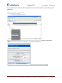
Language, from the drop‐down select the language used on the WebPages. 3.
Session Timeout, How long before you are automatically logged out (when there is no activity) 4.
5.
Customer Username, Customer Password, If you would like to add your own Administrator LOGIN name and PASSWORD use these two fields. Use any Alpha numeric text. Remember it is case sensitive. The password field can be left blank but is not recommended for security reasons. One additional password can be added other than the default username/password “CP Service”/“847‐573‐3800”. Spreader Type, Select from the drop‐down menu the Salt Spreader you have connected to the “Spreader” serial port on the ATS device. Set “Undefined” if no collection of spreader data is required. 6.
7.
8.
Record Spreader status changes, If box is ‘checked’ Instantaneous records are recorded whenever the Spreader changes modes of operation; Auto/Manual, Pause or Blast modes are triggered, Material Lane width change, Liquid system turning ‘On’ and ‘Off’ . Groundspeed Stop/Start. Closed‐loop sensor errors. Default Truck ID, Enter the vehicle/asset ID. This ID should match exactly to what has been saved in the Spreader controller (If used). If no id is typed in the ATS factory default setting populates the ID field with the last 6 digits of its unique wired Ethernet MAC address (see below). Popup Help, Select for on screen help while configuring (highly recommended) Certified Power Inc. 970 Campus Dr. Mundelein, Il 60060 1‐888‐516‐5245 Page 24 Freedom ATS Users Manual: SG07230018 (Manual Data transfer continued: General Setup) 9.
Stack Warning Threshold: Set to 50% 10. Verbose Event Logging: If box is checked detailed logs are recorded for help in troubleshooting. Leave this unchecked unless troubleshooting a problem. Leaving it checked increases usage of system resources such as memory. 11. Breadcrumb rate, Set the rate for which sequential records are stored. Range is 1 to 300 seconds. 3‐15 seconds is typical. Setting the value to “0” disables breadcrumb mode. 12. GPS Installed, If your ATS device is equipped with a GPS check this box to enable it. ATS Part# SG07040078 or SG07040073 would include GPS. ATS Part# SG07040074 or ATSmini part# SG07040087 would not include GPS. 13. Keypad port & type, If the external Login Keypad is installed, choose a PORT number to operate on. Type is TCP. A keypad can only be used on system configured for GL400 Spreader. Always use a port number that is different ‘Server Interface” …see below.. 14. Resident Data Archive Size, Select the Size of the ONBOARD archive file used to store collected data. This is the onboard memory and NOT the SD card. 512K is recommended. The data will wrap and the oldest data will be overwritten when the file allocation is full. 15. Removable Data Archive Size, Select the Size of the REMOVABLE archive file used to store collected data. This is the SD card memory. Do not select a size that is bigger than the installed SD card. The data will wrap and the oldest data will be overwritten when the file allocation is full. Certified Power Inc. 970 Campus Dr. Mundelein, Il 60060 1‐888‐516‐5245 Page 25 Freedom ATS Users Manual: SG07230018 The Server Interface 1.
Logical Interface, Set the interface to “String format 1”. 2.
Port Type, Not applicable for manual data transfer. Leave at default “UDP” 3.
ACK Timeout, Ack (Acknowledge) is not applicable for manual data transfer. Leave at default “2”. 4.
Data Transmit Rate, Not applicable for manual data transfer leave set to default “0”. 5.
Auto Server Selection, Not applicable for Manual Data transfer. Leave at 10 seconds 6.
Physical Interface (primary), For manual data transfer choose NONE for the Physical interface (Primary). Leave (Secondary) interface as “None”. Certified Power Inc. 970 Campus Dr. Mundelein, Il 60060 1‐888‐516‐5245 Page 26 Freedom ATS Users Manual: SG07230018 (manual data‐transfer application continued: The Server Interface cont.) 7. Target IP address, Port Number, Not applicable for manual data transfer 8.
Serial port Settings, Not applicable for manual data transfer Maintenance. (Manual Data transfer continued) 1. Periodically (Per shift, per week, or per month) remove the SD card from the ATS unit. Install the card into your PC or laptops SD card reader using the “ATS Server” software tool part# SGS00300100003 to read the SD Card, moving all the data into a CSV file or into the optional ATS Database Reporting Software SGS00300100002. 2.
Replace the SD Card when finished. The ATS has onboard memory that can be utilized during the time the SD card is out of the unit. It is limited to 512k bytes however (About 12 hours at a 5 second breadcrumb). Using 2 cards in a rotation works well also. Certified Power Inc. 970 Campus Dr. Mundelein, Il 60060 1‐888‐516‐5245 Page 27 Freedom ATS Users Manual: SG07230018 Cellular Modem or LMU Application Guide (Cellular data transfer): Freedom ATS using GPS location and REAL‐TIME CELLULAR DATA TRANSFER with the following features: GPS based vehicle tracking Cellular or LMU Data Link Material data capture Driver initiated Way‐point logging (Optional) Cellular Modem Application GPS SATELLITES
INTERNET
CELL TOWER
VEHICLE EQUIPMENT
CELL
ANTENNA
CELLULAR
MODEM
SERIAL
CABLE
GPS ANTENNA
FREEDOM ATS
SERIAL
CABLE
I/O DEVICES: SWITCHES,
RELAYS, HYDRAULIC
VALVE COILS
COMPUTER
CLIENT
DATABASE
SALT
SPREADER
CONTROL
LMU Application GPS SATELLITES
INTERNET
CELL TOWER
VEHICLE EQUIPMENT
GPS ANTENNA
CELL
ANTENNA
LMU
I/O DEVICES: SWITCHES,
RELAYS, HYDRAULIC
VALVE COILS
SERIAL
CABLE
FREEDOM ATS
SERIAL
CABLE
I/O DEVICES: SWITCHES,
RELAYS, HYDRAULIC
VALVE COILS
SALT
SPREADER
CONTROL
COMPUTER
CLIENT
DATABASE
Certified Power Inc. 970 Campus Dr. Mundelein, Il 60060 1‐888‐516‐5245 Page 28 Freedom ATS Users Manual: SG07230018 Equipment required. (Cellular or LMU Application continued) Freedom ATS unit SG07040074(without GPS) or SG07040078(with GPS), SG07040087 (No GPS, NO SD Card) ATS Server Software part# SGS00300100003 Optional ATS Database Reporting Software SGS00300100002 Basic tools to mount the ATS device and route and splice the wire harness into the vehicle. Summary of hardware installation steps ‐Securely mount ATS device. Use the INSTALLATION and WIRING AND CABLE LAYOUT pictorials as a guide. ‐Securely install cellular modem or LMU using the modem manufacturer’s instructions. ‐Attach fused primary battery and ground wires to devices ‐Attach serial cable to spreader controller. The SG07050647 cable is for use with the ACS, or SG07050056 cable for use with the GL400 or freedom 2. Use the INSTALLATION and WIRING AND CABLE LAYOUT pictorials as a guide. ‐Install GPS window antenna. (If device is has an onboard GPS receiver). ‐Attach wired Ethernet connection between a laptop with a configured static IP address and ATS device. ‐Run through configuration steps as detailed below to complete installation Use your browser to connect to the Web configuration tool as described in the previous section “Accessing the Web Server”. Configure a Cellular or LMU Application General Configuration & Setup 1. Click on the “Install Options” Menu Certified Power Inc. 970 Campus Dr. Mundelein, Il 60060 1‐888‐516‐5245 Page 29 Freedom ATS Users Manual: SG07230018 (Real‐time Cellular or LMU Configuration continued:) Note: Select Pop‐up help to enable the help dialog box as you mouse over items. It is highly recommended to enable this feature unless you are a User that is very familiar with the Application. Note: As you ‘Mouse’ over items on this screen “help messages”Pop‐Up on screen if “pop‐Up” help is selected. 1.
Language, from the drop‐down select the language used on the WebPages. 2.
Session Timeout, How long before you are automatically logged out (when there is no activity) 3.
4.
Customer Username, Customer Password, If you would like to add your own Administrator LOGIN name and PASSWORD use these two fields. Use any Alpha numeric text. Remember it is case sensitive. The password field can be left blank but is not recommended for security reasons. One additional password can be added other than the default username/password “CP Service”/“847‐573‐3800”. Spreader Type, Select from the drop‐down menu the Salt Spreader you have connected to the “Spreader” serial port on the ATS device. Set “Undefined” if no collection of spreader data is required. Certified Power Inc. 970 Campus Dr. Mundelein, Il 60060 1‐888‐516‐5245 Page 30 Freedom ATS Users Manual: SG07230018 (Real‐time Cellular or LMU Configuration continued:) 5.
6.
7.
Record Spreader status changes, If box is ‘checked’ Instantaneous records are recorded whenever the Spreader changes modes of operation; Auto/Manual, Pause or Blast modes are triggered, Material Lane width change, Liquid system turning ‘On’ and ‘Off’ . Groundspeed Stop/Start. Closed‐loop sensor errors. Default Truck ID, Enter the vehicle/asset ID. This ID should match exactly to what has been saved in the Spreader controller (If used). If no id is typed in the ATS factory default setting populates the ID field with the last 6 digits of its unique wired Ethernet MAC address (see below). Popup Help, Select for on screen help while configuring (highly recommended) Certified Power Inc. 970 Campus Dr. Mundelein, Il 60060 1‐888‐516‐5245 Page 31 Freedom ATS Users Manual: SG07230018 (Real‐time Cellular or LMU Configuration continued:) 8.
Stack Warning Threshold: Set to 50% Verbose Event Logging: If box is checked detailed logs are recorded for help in troubleshooting. Leave this unchecked unless troubleshooting a problem. Leaving it checked increases usage of system resources such as memory. 10. Breadcrumb rate, Set the rate for which sequential records are stored. Range is 1 to 300 seconds. 3‐15 seconds is typical. Setting the value to “0” disables breadcrumb mode. 9.
11. GPS Installed, If your ATS device is equipped with a GPS check this box to enable it. ATS Part# SG07040078 or SG07040073 would include GPS. ATS Part# SG07040074 or ATSmini part# SG07040087 would not include GPS. 12. Keypad port & type, If the external Login Keypad is installed, choose a PORT number to operate on. Type is TCP. A keypad can only be used on system configured for GL400 Spreader. Always use a port number that is different ‘Server Interface” …see below.. 13. Resident Data Archive Size, Select the Size of the ONBOARD archive file used to store collected data. This is the onboard memory and NOT the SD card. 512K is recommended. The data will wrap and the oldest data will be overwritten when the file allocation is full. 14. Removable Data Archive Size, Select the Size of the REMOVABLE archive file used to store collected data. This is the SD card memory. Do not select a size that is bigger than the installed SD card. The data will wrap and the oldest data will be overwritten when the file allocation is full. Certified Power Inc. 970 Campus Dr. Mundelein, Il 60060 1‐888‐516‐5245 Page 32 Freedom ATS Users Manual: SG07230018 (Real‐time Cellular or LMU Configuration continued:) The Server Interface 1.
2.
3.
4.
5.
6.
Server logical Interface, Choose the format of the data packets sent to the remote server. The ATS Server software is compatible with “String format 1 & 2”. String Format 1: This is the current Standard format used by the remote ATS Server and Database. String Format 2: This is used for legacy support of older Certified Power applications and is a alternative choice which is also compatible with the Remote ATS Server. Freedom Talk: reserved for future use with FreedomTalk™ compatible applications. Port Type, The only valid selection is UDP. ACK Timeout, Acknowledge must come from the receiving side network. The ATS Server software has capability to send acknowledgement. The “Timeout” sets the time between attempts by the ATS to initiate 2‐way communication to the network server (ATS Server). If set to “0” acknowledge is disabled. Using acknowledge guarantees the receiving device has captured the data packet. 2 seconds is the standard typical setting. Include MAC address; In some cases, such as with an LMU device, it may be desirable to include the complete MAC address of the Wired interface to use as a unique identifier for the piece of equipment in which the ATS is installed. The MAC address will be included on the end of each Data record transmitted from the ATS device. Auto Server Selection, Auto Server Selection sets the timeout period for communication failure across the Primary Interface for which the ATS switches to the secondary interface. The primary interface is always tested periodically and when available the ATS will switch communications back to the Primary Interface. Data Transmit Rate, Data Transmit Rate is a 50% duty cycle mechanism to limit the continuous data transmit rate. The rate when set in seconds is the ON time followed by the OFF time in equal duration. This may be useful when sharing limited bandwidth with many vehicles that often download over a wireless network simultaneously. This feature will greatly extend the amount of time necessary to offload a large amount of data accumulated over several days and should not be used unless deemed necessary. Certified Power Inc. 970 Campus Dr. Mundelein, Il 60060 1‐888‐516‐5245 Page 33 Freedom ATS Users Manual: SG07230018 (Real‐time Cellular or LMU Configuration continued: Configuring the Server Interface) 7.
8.
9.
Physical Interface (primary), Choose your modem or LMU type from the approved modems in the list. Many LMU configurations would use “Serial” as the interface type. Ask your LMU provider for Serial port configuration settings. Serial port settings such as Baud rate and Handshaking can then be programmed. Target IP address, Set the IP address of the destination host for which the ATS Server Application resides. Target Port Number, Set the port number of the destination host for which the ATS Server or other Host Application resides. 10. Serial port Settings, Editing of these settings are not applicable for Standard approved modems however LMU installations may require changing of these settings. For Installations using the “Serial” Selection from the Physical Interface list, these settings can be edited for compatible baud rate and hand‐shaking. 11. Physical Interface (Secondary), Optionally a second physical interface may be selected. It’s set up with its own target IP address and target port number similar to the primary interface. An example may include a the 2‐way radio interface or modem for a primary interface with Wi‐Fi as a secondary interface. When an interface has connectivity the text for “Primary” and conversely “Secondary” will turn green when the physical link is operational. If you don’t require a second interface leave it as ‘None’. The primary interface is used whenever it is available so switching from primary to secondary and back to primary is dynamic. The Secondary interface cannot be the same type of physical interface as the primary. Certified Power Inc. 970 Campus Dr. Mundelein, Il 60060 1‐888‐516‐5245 Page 34 Freedom ATS Users Manual: SG07230018 (Real‐time Cellular Configuration continued:) Modem Configuration and setup 1. Select the “Modem Configuration” page from the menu. 2.
3.
Modem Configuration, For modems selected in the list under Install Options there are always default settings that pre‐populate the fields on this screen. However these options are made available and can be changed if necessary (The example below would be typical of a Multitech CDMA modem on Verizon’s network). Start‐Up Delay, It is recommended to keep the default setting this allows time for the modem to boot properly before being initialized by the ATS. This setting can be used for any modem selected in the list. Maintenance 1. The cellular modem application requires no maintenance or user intervention for normal operation within the vehicle. 2.
Additional tools used for diagnosis of modem problems exist in the “Diagnostics tools/Troubleshooting “ section. Certified Power Inc. 970 Campus Dr. Mundelein, Il 60060 1‐888‐516‐5245 Page 35 Freedom ATS Users Manual: SG07230018 Driveby Download Application Guide (WiFi) Freedom ATS using GPS location and DRIVE‐BY DOWNLOAD data transfer with the following features: GPS based vehicle tracking Built in Wi‐Fi device for data transfer Material data capture Driver initiated Way‐point logging (Optional) CENTRAL OFFICE
WI-FI ANTENNAS
GPS SATELLITES
LIMITED RANGE
ACCESS POINT
VEHICLE EQUIPMENT
COMPUTER
CLIENT
DATABASE
WI-FI ANTENNAS
GPS ANTENNA
FREEDOM ATS
SERIAL
CABLE
I/O DEVICES: SWITCHES,
RELAYS, HYDRAULIC
VALVE COILS
SALT
SPREADER
CONTROL
Equipment required. (Wi‐Fi drive‐by continued) Freedom ATS unit part#SG07040073 Wi‐Fi access point. ATS Server Software part# SGS00300100003 Optional ATS Database Reporting Software SGS00300100002 Basic tools to mount the ATS device and route and splice the wire harness into the vehicle. Summary of hardware installation steps (Wi‐Fi drive‐by continued) ‐Securely mount ATS device. Use the INSTALLATION and WIRING AND CABLE LAYOUT pictorials as a guide. ‐Attach fused primary Battery and ground wires to devices ‐Attach serial cable to spreader controller. The SG07050647 cable is for use with the ACS, or the SG07050056 cable for use with the GL400 or Freedom 2. Use the INSTALLATION and WIRING AND CABLE LAYOUT pictorials as a guide. ‐Install GPS window antenna. ‐Install BOTH Wi‐Fi antennas for full signal strength. ‐Attach wired Ethernet connection between laptop and ATS device ‐Run through configuration steps as detailed below to complete installation Certified Power Inc. 970 Campus Dr. Mundelein, Il 60060 1‐888‐516‐5245 Page 36 Freedom ATS Users Manual: SG07230018 Use your browser to connect to the Web configuration tool as described in the previous section “Accessing the Web Server”. Configure a Wi‐Fi Drive‐by Application General Configuration & Setup 1. Click on the “Install Options” Menu Note: Select Pop‐up help to enable the help dialog box as you mouse over items. It is highly recommended to enable this feature unless you are a User that is very familiar with the Application. Note: As you ‘Mouse’ over items on this screen “help messages”pop‐Up on screen if “pop‐Up” help is selected. Certified Power Inc. 970 Campus Dr. Mundelein, Il 60060 1‐888‐516‐5245 Page 37 Freedom ATS Users Manual: SG07230018 (Wi‐Fi Drive‐by continued: General Configuration & Setup) 1.
Language, from the drop‐down select the language used on the WebPages. 2.
Session Timeout, How long before you are automatically logged out (when there is no activity) 3.
4.
Customer Username, Customer Password, If you would like to add your own Administrator LOGIN name and PASSWORD use these two fields. Use any Alpha numeric text. Remember it is case sensitive. The password field can be left blank but is not recommended for security reasons. One additional password can be added other than the default username/password “CP Service”/“847‐573‐3800”. Spreader Type, Select from the drop‐down menu the Salt Spreader you have connected to the “Spreader” serial port on the ATS device. Set “Undefined” if no collection of spreader data is required. 5.
6.
7.
Record Spreader status changes, If box is ‘checked’ Instantaneous records are recorded whenever the Spreader changes modes of operation; Auto/Manual, Pause or Blast modes are triggered, Material Lane width change, Liquid system turning ‘On’ and ‘Off’ . Groundspeed Stop/Start. Closed‐loop sensor errors. Default Truck ID, Enter the vehicle/asset ID. This ID should match exactly to what has been saved in the Spreader controller (If used). If no id is typed in the ATS factory default setting populates the ID field with the last 6 digits of its unique wired Ethernet MAC address (see below). Popup Help, Select for on screen help while configuring (highly recommended) Certified Power Inc. 970 Campus Dr. Mundelein, Il 60060 1‐888‐516‐5245 Page 38 Freedom ATS Users Manual: SG07230018 (Wi‐Fi Drive‐by continued: General Configuration & Setup) 1.
2.
3.
4.
Stack Warning Threshold: Set to 50% Verbose Event Logging: If box is checked detailed logs are recorded for help in troubleshooting. Leave this unchecked unless troubleshooting a problem. Leaving it checked increases usage of system resources such as memory. Breadcrumb rate, Set the rate for which sequential records are stored. Range is 1 to 300 seconds. 3‐15 seconds is typical. Setting the value to “0” disables breadcrumb mode. GPS Installed, If your ATS device is equipped with a GPS check this box to enable it. ATS Part# SG07040078 or SG07040073 would include GPS. ATS Part# SG07040074 or ATSmini part# SG07040087 would not include GPS. 5. Keypad port & type, If the external Login Keypad is installed, choose a PORT number to operate on. Type is TCP. A keypad can only be used on system configured for GL400 Spreader. Always use a port number that is different ‘Server Interface” …see below.. 6.
7.
Resident Data Archive Size, Select the Size of the ONBOARD archive file used to store collected data. This is the onboard memory and NOT the SD card. 512K is recommended. The data will wrap and the oldest data will be overwritten when the file allocation is full. Removable Data Archive Size, Select the Size of the REMOVABLE archive file used to store collected data. This is the SD card memory. Do not select a size that is bigger than the installed SD card. The data will wrap and the oldest data will be overwritten when the file allocation is full. Certified Power Inc. 970 Campus Dr. Mundelein, Il 60060 1‐888‐516‐5245 Page 39 Freedom ATS Users Manual: SG07230018 The Server Interface 12. Server logical Interface, Choose the format of the data packets sent to the remote server. The ATS Server software is compatible with “String format 1 & 2”. a. String Format 1: This is the current Standard format used by the remote ATS Server and Database. b. String Format 2: is used for legacy support of older Certified Power applications and is a alternative choice which is also compatible with the Remote ATS Server. c. Freedom Talk: This is for future use with freedom Talk compatible Applications. 13. Port Type, The only valid selection is UDP. TCP/IP may be available in the future. 14. ACK Timeout, Acknowledge must come from the receiving side network. The ATS Server software has capability to send acknowledgement. The “Timeout” sets the time between attempts by the ATS to initiate 2‐way communication to the network server (ATS Server). If set to “0” acknowledge is disabled. Using acknowledge guarantees the receiving device has captured the data packet. 15. Data Transmit Rate, Data Transmit Rate is a 50% duty cycle mechanism to limit the continuous data transmit rate. The rate when set in seconds is the ON time followed by the OFF time in equal duration. This may be useful when sharing limited bandwidth with many vehicles that often download over a wireless network simultaneously. This feature will greatly extend the amount of time necessary to offload a large amount of data accumulated over several days and should not be used unless deemed necessary. 16. ACK timeout, Typically this value is set between 2 (recommended) and 5 seconds . This sets the repetition rate of each packet of data until an acknowledge has been received for that packet. If set to ‐0‐ the ATS sends data without acknowledge from the receiving side. If (Ack)nowledge is not used it is probable for large amounts of data to be lost. 17. Auto Server Selection, Auto Server Selection sets the timeout period for communication failure across the Primary Interface for which the ATS switches to the secondary interface. The primary interface is always tested periodically and when available the ATS will switch communications back to the Primary Interface. Certified Power Inc. 970 Campus Dr. Mundelein, Il 60060 1‐888‐516‐5245 Page 40 Freedom ATS Users Manual: SG07230018 (Wi‐Fi Drive‐by continued: The Server Interface cont.) 18. Physical Interface (Primary), Choose “Wireless“ from the drop‐down list. 19. Target IP address, Set the IP address of the destination host for which the ATS Server Application resides. 20. Target Port Number, Set the port number of the destination host for which the ATS Server or other Host Application resides. 21. Serial port Settings, Not Applicable for Wi‐FI installation 22. Physical Interface (Secondary), Optionally a second physical interface may be selected. It’s set up with it’s own target IP address and target port number similar to the primary interface. An example may be a modem. When an interface has connectivity the text for “Primary” and conversely “Secondary” will turn green when the physical link is operational. If you don’t require a second interface leave it as ‘None’. You cannot choose the same primary and secondary interface types. Certified Power Inc. 970 Campus Dr. Mundelein, Il 60060 1‐888‐516‐5245 Page 41 Freedom ATS Users Manual: SG07230018 Wireless Configuration. (Wi‐Fi drive‐by continued) 1. Select the Wireless Configuration page from the menu. The “Wireless Configuration” is only visible if the “Wireless” option has been chosen under “Installation Options” the “Physical interface” 2.
It will be necessary to add your wireless access point settings/passwords/and configure levels of encryption if required using this page. Note: Also Access‐point signal strength is displayed on the page. Note: As Different Authentication methods and Encryption methods are selected fields that do not pertain to those methods will grayed out. Note: A Glossary of terms regarding Wi‐Fi security is included in the back of this manual. Below is an EAP Fast setup example. A “PAC” file is stored in on‐board flash memory and can be seen through the “File Management” menu after successfully connecting to the to your gateway for the first time. Certified Power Inc. 970 Campus Dr. Mundelein, Il 60060 1‐888‐516‐5245 Page 42 Freedom ATS Users Manual: SG07230018 Network Configuration (Wi‐Fi drive‐by continued) 1. Click the “Network Configuration” Settings page. 1.
2.
3.
4.
5.
“DHCP” (service client) or “Use Static IP”, The Wireless Interface typically would be left as DHCP. However each Access point must have DHCP service available. If DHCP is a problem then a static address may be used such as the example listed below. Default Gateway, A gateway may or may not be required for network routing. Check with your Systems Administrator. IP address, It is recommended that you leave the default WIRED address as it is, and ALWAYS as a static address. If you change the address please note it for future reference. NEW address: HTTP://______.______.______.______. The static address insures the ability to connect to the Web Server at any time regardless of network services like DHCP. Subnet Mask, Typically set to 255.255.255.0 for use on IPv4 typical private networks. DNS, Primary and Secondary DNS is for future use Maintenance 1. All configuration and maintenance through the Web Server is available using the Wireless port when the vehicle is on the network. 2. The Drive‐by‐download application requires no maintenance or user intervention for normal operation within the vehicle. Certified Power Inc. 970 Campus Dr. Mundelein, Il 60060 1‐888‐516‐5245 Page 43 Freedom ATS Users Manual: SG07230018 ATS mini A simplified Gateway for communications with Certified Power Spreader controls Used for Safe and reliable communications interface between external equipment and Salt Spreader controllers such as the GL400 and Joystick and Spreader control consoles such as the ACS Systems. Supports 2‐way communication for Remote Fleet Management. Simplified cost reduced Hardware, No SD Card, Digital Ins/Outs, Wifi, GPS or RoadWatch™ Capability. Data can be transferred through serial port to any Modem, LMU or Radio utilizing an RS‐232 serial port. Periodic on‐board Flash Memory back‐up of real‐time data helps prevent data‐loss over Power‐loss or intermittent network connections. Works with Freedom ATS Server Software and ATS Reporting Database. Easy configuration and maintenance over the wired Ethernet interface. VEHICLE EQUIPMENT
LMU/MODEM
OR RADIO
SERIAL
CABLE
FREEDOM
ATS mini
SERIAL
CABLE
SALT
SPREADER
CONTROL
Equipment required. Freedom ATS unit part#SG07040087 Optional ATS Server Software part# SGS00300100003 Optional ATS Database Reporting Software SGS00300100002 Basic tools to mount the ATS device and route and splice the power harness into the vehicle. Summary of hardware installation steps ‐Securely mount ATS device. Use the INSTALLATION and WIRING AND CABLE LAYOUT pictorials as a guide. ‐Attach fused primary Battery and ground wires to devices ‐Attach serial cable to spreader controller. The SG07050647 cable is for use with the ACS, or the SG07050056 cable is for use with the GL400 or freedom 2 controls. ‐Attach serial cable to Modem, or LMU. In many case the SG07050647 cable is compatible for use in connecting these devices as well. The ATS Serial port is a male DB‐9 configured as a Computer type connection. Use the INSTALLATION and WIRING AND CABLE LAYOUT pictorials as a guide. ‐Attach wired Ethernet connection between a staic IP address configured laptop and ATS device. ‐Run through configuration steps as detailed below to complete installation Certified Power Inc. 970 Campus Dr. Mundelein, Il 60060 1‐888‐516‐5245 Page 44 Freedom ATS Users Manual: SG07230018 Using your browser connect to the Web configuration tool as described in the section at the beginning of the manual “Accessing the Web Server”. (Configuring an ATSmini continued: General Configuration & Setup) Configure an Application using the ATS Mini General Configuration & Setup 1. Click on “Install Options”, The application and hardware setup occurs on this screen. 2.
Note: As you ‘Mouse’ over items on this screen “help messages” pop‐Up on screen if “pop‐Up” help is selected. 3.
Click on the “Install Options” Menu Note: Select Pop‐up help to enable the help dialog box as you mouse over items. It is highly recommended to enable this feature unless you are a User that is very familiar with the Application.
Certified Power Inc. 970 Campus Dr. Mundelein, Il 60060 1‐888‐516‐5245 Page 45 Freedom ATS Users Manual: SG07230018 (Configuring an ATSmini continued: General Configuration & Setup) Note: As you ‘Mouse’ over items on this screen “help messages”Pop‐Up on screen if “pop‐Up” help is selected. 1.
Language, from the drop‐down select the language used on the WebPages. 2.
Session Timeout, How long before you are automatically logged out (when there is no activity) 3.
4.
Customer Username, Customer Password, If you would like to add your own Administrator LOGIN name and PASSWORD use these two fields. Use any Alpha numeric text. Remember it is case sensitive. The password field can be left blank but is not recommended for security reasons. One additional password can be added other than the default username/password “CP Service”/“847‐573‐3800”. Spreader Type, Select from the drop‐down menu the Salt Spreader you have connected to the “Spreader” serial port on the ATS device. Set “Undefined” if no collection of spreader data is required. 5.
6.
7.
Record Spreader status changes, If box is ‘checked’ Instantaneous records are recorded whenever the Spreader changes modes of operation; Auto/Manual, Pause or Blast modes are triggered, Material Lane width change, Liquid system turning ‘On’ and ‘Off’ . Groundspeed Stop/Start. Closed‐loop sensor errors. Default Truck ID, Enter the vehicle/asset ID. This ID should match exactly to what has been saved in the Spreader controller (If used). If no id is typed in the ATS factory default setting populates the ID field with the last 6 digits of its unique wired Ethernet MAC address (see below). Popup Help, Select for on screen help while configuring (highly recommended) Certified Power Inc. 970 Campus Dr. Mundelein, Il 60060 1‐888‐516‐5245 Page 46 Freedom ATS Users Manual: SG07230018 1.
2.
3.
4.
Stack Warning Threshold: Set to 50% Verbose Event Logging: If box is checked detailed logs are recorded for help in troubleshooting. Leave this unchecked unless troubleshooting a problem. Leaving it checked increases usage of system resources such as memory. Breadcrumb rate, Set the rate for which sequential records are stored. Range is 1 to 300 seconds. 3‐15 seconds is typical. Setting the value to “0” disables breadcrumb mode. GPS Installed, If your ATS device is equipped with a GPS check this box to enable it. ATS Part# SG07040078 or SG07040073 would include GPS. ATS Part# SG07040074 or ATSmini part# SG07040087 would not include GPS. 5. Keypad port & type, If the external Login Keypad is installed, choose a PORT number to operate on. Type is TCP. A keypad can only be used on system configured for GL400 Spreader. Always use a port number that is different ‘Server Interface” …see below.. 6.
7.
Resident Data Archive Size, Select the Size of the ONBOARD archive file used to store collected data. This is the onboard memory and NOT the SD card. 512K is recommended. The data will wrap and the oldest data will be overwritten when the file allocation is full. Removable Data Archive Size, Not an available default equipment option. Leave setting at default setting of 256Mb. Certified Power Inc. 970 Campus Dr. Mundelein, Il 60060 1‐888‐516‐5245 Page 47 Freedom ATS Users Manual: SG07230018 The Server Interface (Configuring an ATSmini continued: General Configuration & Setup) 23. Physical Interface (primary), Choose your modem or LMU type from the approved modems in the list. Many LMU configurations would use “Serial” as the interface type. Ask your LMU provider for Serial port configuration settings. Serial port settings such as Baud rate and Handshaking can then be programmed. 24. Target IP address, Set the IP address of the destination host for which the ATS Server Application resides. If the interface is “Serial” the IP address field will be grayed out and should be ignored. 25. Target Port Number, Set the port number of the destination host for which the ATS Server or other Host Application resides. If the interface is “Serial” the Port Number field will be grayed out and should be ignored. 26. Serial port Settings, Editing of these settings are not applicable for Standard approved modems however LMU installations may require changing of these settings. For Installations using the “Serial” Selection from the Physical Interface list, these settings can be edited for compatible baud rate and hand‐shaking. 27. Physical Interface (Secondary), Not typically required for applications utilizing an ATS mini. ‐This concludes setup of the ATS mini. Certified Power Inc. 970 Campus Dr. Mundelein, Il 60060 1‐888‐516‐5245 Page 48 Freedom ATS Users Manual: SG07230018 Input Configuration General Setup of inputs 1. Select Input Configuration from the on‐screen menu. You must be logged in as Administrator to see the “Input Configuration” link. 2.
The following text describes the features and functions available through the “Inputs Configuration” screen. Certified Power Inc. 970 Campus Dr. Mundelein, Il 60060 1‐888‐516‐5245 Page 49 Freedom ATS Users Manual: SG07230018 1.
Function, Select the function for the input (1‐8) that you would like to configure. Undefined, This is the DEFAULT selection for inputs that are disabled. User Defined, Use this setting when you need a “Named” input. See “Name” below. Data Download, Configure an input to use for Data‐download switch. Only one input can be used for the Data‐download input. (Required for “Push‐button data download application”) Function Predefined: pre‐Defined names in the list from Front Plow to Low Liquid are required to include as part of the legacy support for older systems. The ATS Server shows the state of these inputs real‐time on the Lower right portion of the Main Screen. Low Speed and High Speed Counter. See Topic below “Counter Input Configuration” 2.
Name, Assign a ‘name’ using any alpha numeric function such as “Plow”. This field can only be used for “User defined” function above. 3.
Active State, Low High. This sets the ACTIVE state of a valid input. Setting a Low defines the input is valid when pulled to ground. Setting a High state defines the input as valid when pulled to battery level. Note: “Active low” applies a pull‐up voltage equal to ½ Battery Supply. to the pin. The current through the pin is 8.06mA when the input is shorted to ground. Note: “Active high” applies a pull‐down resistor between ground and the input pin. The current through the pin is 3.8mA when the input is shorted to Battery. Active/Inactive text, Define text to be displayed when the input is ‘Active’ or ‘InActive’ such as “Up” or “Down”.
4.
Note: Using the example above for NAME “Plow”; and combining that with the input “active” state and [Text] such as “UP” would result in an “active” state logged as “Plow Up” or “Plow Down” as corresponds to the “inactive” {text] box being filled in as “Down” Note: Check the “Event logs” to view input status or to test the input circuit Severity, Define whether the input will be recorded as an “Error” or as a “status” message. The severity level will be used to help prioritize messages on the management side using the remote client/server.
5.
Certified Power Inc. 970 Campus Dr. Mundelein, Il 60060 1‐888‐516‐5245 Page 50 Freedom ATS Users Manual: SG07230018 Counter Input Configuration Low Speed Counter Input. Inputs 1‐8 of the 8 inputs on the ATS device can be used as low Speed Frequency counters for any sensor with a Square wave digital output such as Hall Sensors used on Augers, Conveyors, Wheels, Flow‐Meters or Gear Boxes. The input is capable of reading frequencies to 300Hz. The Sensor must be able to switch currents up to 8 milliamps. Follow the configuration steps outlined below. A High Speed counter is available on input 8 ONLY, capable of frequencies up 5KHz. 1.
2.
3.
4.
5.
6.
Function, Select Low Speed Counter Active State, Select Active State. Selecting Active Lows turns on the internal Pull‐up resistor inside the ATS. This would be typical of a Hall Sensor input. Turn On Active high for any Sensor that Switches battery level voltages. Active High would also being used for any output from a Computer or signal generator that is TTL compatible. Name, It is assumed the counter is used for a granular or liquid Application. Type “Liquid” or “Solid” being careful to use exact case shown. The ATS Server will reflect the counter value in the “Granular Weight” or “Liquid Total” field. Active/Inactive Text, Ignore Active and Inactive text Fields. Severity, Ignore the Severity fields. Counts, Enter a pulse count Per “Gallon” or “Pound” units. Counter Input Calibration (Viewing Counts using the built in Pulse Counter) 1. To use the built in pulse counter on the Inputs Configuration page, first Select the Function “Low” or “High Speed Counter” and It’s Active State. Reboot the ATS System. 2. The Counter input can be calibrated by leaving Counts at” 0” and Per set to “Undefined”. In this configuration when counts are received they are stored internally, simply refreshing the page at anytime will show the active count total. 3. To clear the counts a. Change Undefined to “Pound” or “Gallon” b. . Change the count to ‐0‐ c. Change “Per” back to “Undefined”. d. Click the “Apply” changes button on the bottom of the page. To Save a calibrated value up to .001 resolution directly enter the value into “Counts” after Selecting “Pound” or “Gallon” from Per. Use the example below to calculate pulse Counts Example, Dry material, 300 lbs weighed and 120 pulses counted. 120/300= .4 cal factor. Always divide your pulses by the weight of material dispensed. Certified Power Inc. 970 Campus Dr. Mundelein, Il 60060 1‐888‐516‐5245 Page 51 Freedom ATS Users Manual: SG07230018 Diagnostic tools/Troubleshooting Assistance Diagnostic LED’s. 1. The LED status codes are universal for all the RED status LED’s located on the side of the ATS unit. The code is as follows: a. Lights that Blink at a fast rate confirm normal operation. b. Light that blink at a slow rate 1 sec. on 1 sec. off indicate a service that is down. c. Lights that are off indicate a service that has been disabled in configuration. 2. “Spreader Act”, If the Spreader controller is powered on and a serial cable is properly attached the “SPREADER ACT” light should be blinking fast. Remember for ACS units “AVL” & “AVL Type”must be enabled internally in the “System Settings” menu. For GL400’s only software installed in GL400‐7’s :”rev. 18” is compatible with the ATS. 3. “GPS Act”, If the GPS receiver is operational the GPS receiver light should be blinking fast. Normal fast blink operation does not include requiring a Satellite fix. 4. “Remote Server”, With a remote server configured for Cellular Link, Wi‐Fi LAN or Wired LAN (Ethernet) a fast blink reflects network connectivity under No ACK configuration. If ACK is required under “Install options” the light will blink slowly until ACK is received from the remote Server. The WLAN (Wi‐Fi) or wired LAN of course include activity lights. While configuring the ATS under the Options Menu The “Primary” and “Secondary” interface text high‐lights Green when the Physical link is Up and “Black” when it’s down. When making changes to the “Physical” interface settings a reboot is required before the link may come up. 5. “Road/Air Temp”, If a signal is received from a Sprague Devices RoadWatch SS™ sensor this light will blink fast. 6. “System Status”, If this light is solid ‘ON’ the ATS is configured with an IP address of 192.168.11.120. Any other IP address will result in the light blinking fast. 7. “SD Card Status”, If an SD card is installed and the ATS unit is successfully reading and writing data to the card this light will blink fast. Don’t forget SD cards have a write‐protect switch. If the switch is in the “Lock” position the ATS cannot write to the card and the LED status light will blink slowly. If no Card is installed in the slot the status light is ‘Off’. Often the write‐protect is turned ‘ON’ accidentally when sliding the card into the metal housed card carrier or you PC’s SD card reader slot. Certified Power Inc. 970 Campus Dr. Mundelein, Il 60060 1‐888‐516‐5245 Page 52 Freedom ATS Users Manual: SG07230018 GPS Viewer (Diagnostics and Troubleshooting cont.) 1.
Select the “GPS Viewer” from the main menu. Use the GPS viewer to observe real‐time data streaming from the GPS receiver. Typically these settings should not be changed. A minimum of 3 satellites are required for location & direction. 4 satellites are required for Altitude and velocity. There are two types of GPS receivers used in ATS the Lassen IQ or Condor. Generally speaking ATS’s sold after Sept of 2012 have Condor GPS receivers. Certified Power Inc. 970 Campus Dr. Mundelein, Il 60060 1‐888‐516‐5245 Page 53 Freedom ATS Users Manual: SG07230018 (Diagnostics and Troubleshooting cont. Event/Error log 1. “Verbose Event Logging” must be checked under the “Install Options” screen to see detailed Error and Event logging. It is recommended only to use “Verbose” logging while troubleshooting a problem. It’s recommended to keep the option ‘Off’ in normal operation.
Status logs give information about status of services . o Works in unison with status LED’s located on ATS device user’s panel. o GPS receiver o Remote Server o Road‐Watch o ATS System health o Spreader link o SD Card Card Detect (See previous section on “Diagnostic LED’s” section for info on SD Write‐Protect) o Status level severity inputs Error logs report errors that will affect system services o Corrupt atsconfig.bin files o Error level severity inputs. o GPS Antenna connection problems Status and Errors can be cleared using the provided buttons on the webpage. Certified Power Inc. 970 Campus Dr. Mundelein, Il 60060 1‐888‐516‐5245 Page 54 Freedom ATS Users Manual: SG07230018 Modem status (Diagnostics and Troubleshooting cont.) 1. View modem serial port control lines to modem (Useful for modem troubleshooting) This screen shows the status of the physical control lines exiting the Modem RS‐232 serial port located on the side of the ATS unit. This can be useful if diagnosing problems relating to the modem serial port. The below screen pictured below would be typical for the (tested ) Multi‐tech manufactured modem when a valid cellular network connection has been established. Certified Power Inc. 970 Campus Dr. Mundelein, Il 60060 1‐888‐516‐5245 Page 55 Freedom ATS Users Manual: SG07230018 Updating firmware/Loading defaults/Restoring your settings Updating firmware 1. Before updating firmware, It is highly recommended to save your “Atsconfig.txt” file to your laptop computer. Use the menu “Save configuration” to save your current settings (both files AtsConfig.txt & AtsConfig.bin will be saved to the onboard SD Card). 2.
3.
4.
After saving the files remove the SD card cover then the SD Card from the side of the ATS unit. Using an SD to USB Card Reader to access the files on the SD card from yout Laptop or Desktop computer; move the files “AtsConfig.bin” & “AtsConfig.txt” onto your computer. If you are doing a firmware upgrade you will not be able to use your saved “AtsConfig.bin” file so delete/discard this file, however you will be able to open your AtsConfig.txt file in Microsoft WordPad™ to see your old settings for manual configuration. Once you have saved your AtsConfig.txt file to you laptop and deleted the old AtsConfig.bin file continue to the next step. It is not necessary to re‐install the SD Card until you are instructed to do so in the later steps of this procedure. 3 files files are needed when updating firmware on an ATS system. Rom.bin Image.bin Backup.bin (V5.0 and higher) Click on “Upload Firmware” menu item.
5.
The file selection dialogue box should then appear
6.
7.
Select the “rom.bin” file using the “Browse” button. Upload the file using the “Upload” button. (Continued on next page) Certified Power Inc. 970 Campus Dr. Mundelein, Il 60060 1‐888‐516‐5245 Page 56 Freedom ATS Users Manual: SG07230018 8.
9.
The ATS will reboot on it’s own. It may be necessary to browse back to the ATS and re‐login again if the page does not refresh on it’s own. The System status LED on the side of the ATS unit should be blinking fast indicating normal operation has resumed; when it is ok to browse the Web server again. Repeat the process loading the “Image.bin” file. Again the system will reboot itself. See Note below. Verify the correct version numbers are listed on the “Home” page. Note: In some cases after loading image.bin the ATS may no longer be reachable when trying to navigate to the Webpage. If this happens most likely the default IP address has been applied. This scenario can be verified as occurring if the System Status light is on SOLID. Navigate to 192.168.11.120 and change the IP address back to your specified address setting, then reboot the ATS and continue to the next step. 10. If your firmware version is v5.0 or higher than you must also install a file called “Backup.bin”. Repeat the process loading the “Backup.bin” file. Again the system will reboot itself. Verify the correct version numbers are listed on the “Home” page. (Restoring your application is covered on the next page.) Restoring your Application Options and Setup 11. Once the firmware upgrade has been successful and version numbers have been verified. In most cases the system configuration options will need to be restored. If you have been provided a new “ATSconfig.bin” file then you will need to install the file onto your SD Card after completing the firmware upgrade. *See Note below. The binary file ATSConfig.bin file will need to be placed on the SD Card. Use your SD card reader and you laptop to do this. Install the SD Card with the AtsConfig.bin file into the slot on the newly upgraded ATS unit. Reboot the ATS unit. On start‐up the AtsConfig.bin file checksum is always verified and then the file is loaded. If you see the ATS reboot on it’s own after about 10 seconds then the file was loaded successfully, and all your settings have been restored. See the section at the beginning of the manual on “Restoring a saved file” for information on the “File Management” screen and AtsConfig.bin file. Note: After a firmware update, checking the Event log, and most likely you will see several entries similar to the example shown below. This is typical when default factory settings have been set. The log files can be cleared using “Clear” button under “Event Log”. 12. If you don’t have an updated AtsConfig.bin file compatible to your upgraded version (Usually provided by Certified Power or one you created from your first upgrade), then you may need to manually enter your settings. View your saved AtsConfig.txt file in Microsoft WordPad™. 13. Once the system is configured save a new “ATSconfig.bin” file and archive a copy on your laptop or PC for future use if needed or use it to update other ATS units that also need a firmware update. See the Section under “Setup and Configuration” for help on saving and restoring config files using the SD card. 14. Below is an example “AtsConfig.txt” file as viewed through Microsoft WordPad™. This is a hard‐copy of all your configuration options and settings. Certified Power Inc. 970 Campus Dr. Mundelein, Il 60060 1‐888‐516‐5245 Page 57 Freedom ATS Users Manual: SG07230018 Deleting a Configuration (Restoring defaults) Check the box to the right of the NVDPDb.bin (Native data point data‐base) file then press the “Delete file(s)” button. Remove the SD card and delete all files off the SD card using a PC and card reader. Rebooting the system will then force the rebuilding of this file using factory settings. The ATS device will be restored to factory defaults. Certified Power Inc. 970 Campus Dr. Mundelein, Il 60060 1‐888‐516‐5245 Page 58 Freedom ATS Users Manual: SG07230018 WiFi Setup & Security (Glossary of terms) The ATS wireless configuration web page is where users establish the devices wireless configuration. The following is a brief list of terms and definitions to aid in understanding the wireless configuration of the ATS. Additional information can be found in the IEEE 802.11 standard for wireless networks. Association – Involves the exchange of capability information between the ATS and the AP to establish access. After association, the ATS can send and receive data through the access point unless an additional security mechanism is in place. Authentication – The procedure the wireless section of the ATS goes through to prove that it is a member of an AP. Encryption ‐ Encryption is the conversion of data into a form, called a cipher, that cannot be easily understood by unauthorized people. Antenna diversity ‐ Most 802.11 interfaces have two antennas for antenna diversity to improve reception in the presence of multipath interference. Short preamble – Part of data frame transmitted by an 802.11 station is called the preamble. The original 802.11 specification (which defined only 1 and 2Mbps operation), defined only a long preamble that uses a 128 bit sync field. When the "high rate", i.e. 11Mbps, 802.11b standard was created, an optional short preamble using a 56 bit "sync" field was added. This was intended to improve the efficiency of the wireless network for more "real‐time" applications. 802.11 devices in the 2.4 GHz band, including 802.11g devices, must be able to transmit and receive long preamble frames. 802.11g devices are required to be able to transmit and receive both long and short preambles, but support for short preamble in 802.11b devices is optional. Server certificate verification ‐ This feature is only available when using Secure Socket Layer for secure communications over unsecured networks. Currently, the ATS does not make use of SSL. Use only 802.11b rates – Instructs ATS to use only the 2.4 GHZ band. Use RTS/CTS protection frames for 802.11g – This feature is used to avoid interference between 802.11g and 802.11b networks. Sometimes, such as in the presence of RF interference, it is beneficial to break larger frames into smaller frames before transmission across a wireless link. The 802.11 standard defines fragmentation as an optional function, and it can be initiated on either the client station or the access point or both. Fragmentation is unique to each wireless link. Use fixed transmit rate – Typically, the ATS wireless transceiver is set to automatically transmit data with a range of 1 to 54Mbps. Enabling fixed transmit rates means the ATS will transmit only at the selected data rate. If using a fixed transmit rate, the AP’s must be enabled to send/receive at this data rate. 802.11 Multi domain capability (802.11d) – 802.11d is a wireless network communications specification for use in countries where systems using other standards in the 802.11 family are not allowed to operate. Power‐save ‐ Wireless transceivers can consume significant power. The optional power‐save function allows the ATS wireless transceiver to periodically shutdown and startup, which uses much less power. Access points must support this feature in order for this feature to function properly. 802.11h spectrum management – Used to solve problems like interference with satellites and radar using the same 5 GHz frequency band. It was originally designed to address European regulations but is now applicable in many other countries. Certified Power Inc. 970 Campus Dr. Mundelein, Il 60060 1‐888‐516‐5245 Page 59