1
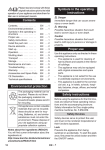
Model: DR3 DOUGLAS® RAPTOR™ HF Rapid Charger Owner’s Manual To automatically be connected to your closest Service Center, call us toll-free at 1-800-DOUGLAS (1-800-368-4527) Or, visit us at: http://www.douglasbattery.com/ I.B.1650 Rev A (4/15) IMPORTANT Read and understand your user’s manual before installing, operating, or servicing this product. DO NOT DESTROY THIS BOOK Douglas Raptor Fast Charger Owner’s Manual I.B.1650 TABLE OF CONTENTS AC Line Voltage Letter Codes ............. 2 Specialty Charger Option List ............. 2 Important Safety Instructions .............. 3 Technical Information........................... 4 Information ...................................... 14 Password ......................................... 14 Modular……………………………….15 Charging the Battery ...................... 16 Part Number ............................................ 4 Serial Number ......................................... 4 Battery Type ............................................ 4 Ampere-Hours ......................................... 4 Cells ........................................................ 4 Input AC Volts ......................................... 4 Input AC Amps ........................................ 4 Hz ............................................................ 4 Phase ...................................................... 4 DC Volts .................................................. 4 Rated DC Amps ...................................... 5 Charger Idle Display ......................... 16 Delayed Start .................................... 17 Starting a Charge Cycle.................... 17 Effective Charge ............................... 17 End of Charge w/o Equalize ............. 18 End of Charge with Equalize ............ 18 Fault Codes ..................................... 19 Maintenance & Service ......................... 20 Replacement Parts 24/36/48V .............. 21 Replacement Parts 72/80V ................... 22 Technical Specifications……………….23 3 Bay Cabinet Dimensions ................... 24 6 Bay Cabinet Dimensions ................... 25 Maintenance Log................................... 26 Installation ............................................. 5 Location ................................................... 5 Electrical Connections ............................ 5 On three phase units ............................... 5 Connecting Input Power .......................... 5 AC Connection ........................................ 5 Plug Polarity ............................................ 5 Grounding the Charger ........................... 5 Install Thermistor……………………..…..5 Description of Operation ...................... 6 General ................................................... 6 Starting the Charge ................................. 6 Charging .................................................. 6 AC Power Fail ......................................... 6 Series Charging ...................................... 6 Glossary................................................. 7 Charging Coefficient................................ 7 Charging Profile ...................................... 7 Equalization Charging ............................. 7 Refresh Charging .................................... 7 External Components…………………..8 Operating Instructions ......................... 9 Charger Control Panel .................... 9 LCD Display Colors…………………9 Key Functions………………………..9 Module Management……………….10 Menu Access ................................... 11 Main Menu ........................................ 11 Memorizations ................................. 11 Status ............................................... 12 Parameters ............................................ 13 Date/Time ................................................ 13 Serial Number ......................................... 13 Language ................................................ 13 Region ..................................................... 13 Contrast ................................................... 13 Backlight……………………………….…..13 1 Douglas Raptor Fast Charger Owner’s Manual I.B.1650 AC LINE VOLTAGE LETTER CODES The following table describes the code letters to be used in new charger part numbers to indicate the AC line voltage(s) and AC line frequency at which the charger can be operated. Code Letters Voltage(s) (volts rms) Y C 480 600 Line Frequency (Hertz) 50/60 50/60 Comments 480 VAC only 600 VAC only SPECIALTY CHARGER OPTIONS LIST Suffix L16 L23 L30 NC PP S Description 16' of DC cable. 23' of DC cable. 30' of DC cable. No DC cables ( NOT UL APPROVED) Charger shipped on a Plastic Pallet Series DC Cables 2 Douglas Raptor Fast Charger Owner’s Manual I.B.1650 IMPORTANT SAFETY INSTRUCTIONS 1. This manual contains important safety and operating instructions. Before using the battery charger, read all instructions, cautions, and warnings on the battery charger, the battery, and the product using the battery. 2. This charger has been designed to only charge flooded, lead-acid batteries. Read and understand all setup and operating instructions before using the battery charger to prevent damage to the battery and to the charger. 3. Do not touch non-insulated parts of the output connector or the battery terminals to prevent electrical shock. 4. During charge, batteries produce hydrogen gas which can explode if ignited. Never smoke, use an open flame, or create sparks in the vicinity of the battery. Ventilate well when the battery is in an enclosed space. 5. Do not connect or disconnect the battery plug while the charger is on. Doing so will cause arcing and burning of the connector resulting in charger damage or battery explosion. 6. Lead-acid batteries contain sulfuric acid which causes burns. Do not get in eyes, on skin, or on clothing. In cases of contact with eyes, flush immediately with clean water for 15 minutes. Seek medical attention immediately. 7. Only factory qualified personnel can service this equipment. De-energize all AC and DC power connections before servicing the charger. 8. The charger is not for outdoor use. 9. Do not expose the charger to moisture. Operating conditions should be 0º to 104º F; 0 to 70% relative humidity. 10. Do not operate the charger if it has been dropped, received a sharp hit, or otherwise damaged in any way. 11. For continued protection and to reduce the risk of fire, install chargers on a floor of non-combustible material such as stone, brick, or grounded metal. WARNING: The shipping pallet must be removed for proper and safe operation. INSTRUCTIONS DE SÉCURITÉ IMPORTANTES 1. Ce manuel contient des informations et des consignes importantes pour l’emploi et l’utilisation du chargeur de batteries industrielles. Avant tout emploi, il est fortement conseillé de lire l’ensemble des instructions, recommandations, et avertissements concernant le chargeur et la batterie. 2. Ce chargeur a été conçu pour la charge des batteries industrielles type plomb-acide dite « ouverte ». (Il ne peut pas être adapté pour les batteries étanches.) 3. Lisez toutes les condisnes d’installation et d’utilisation avant d’employer le chargeur de batterie pour empêcher des dommages à la batterie et / ou au chargeur. 4. Ne pas être en contact avec les pièces sous-tension non-isolées tels que la prise de charge ou des éléments de connexion de la batterie pour empêcher le choc électrique. 5. Pendant la charge, le dégagement d’hydrogène rend l’emploi de feu strictement interdit «risque d’explosion ». Ne jamais fumer, employer une flamme nue, ou créez les étincelles à proximité de la batterie. Ventiler suffisamment pour éviter toute condensation de gaz dans un espace restreint. 6. Ne brancher ou débrancher la batterie que si le chargeur est à l’arrêt. Faire ainsi risque d’endommager la prise de charge pouvant avoir pour conséquence des dommages du chargeur ou l’explosion de la batterie. 7. Les batteries d’acide au plomb contiennent l’acide sulfurique, qui cause des brûlures. Eviter le contact avec les yeux, la peau, ou sur l’habillement. Dans le cas de contact avec les yeux, et faut nettoyer immédiatement avec de l’eau propre pendant 15 minutes et consulter un médecin immédiatement. 8. Seul le personnel qualifié par l’usine peut entretenir cet équipement. Pour le service, veuillez contacter la société Douglas ou l’un de ces représentant (1-800-DOUGLAS) (1-800-368-4527) 9. Avant toute intervention d’entretien ou de réparation il faut s’assurer que le chargeur est hors tension et la batterie est déconnectée. 10. Le chargeur n’est pas pour un usage extérieur. 11. Ne pas exposer le chargeur à l’humidité. Les conditions de fonctionnement devraient être – 15° à 40°c; humidité relative de 0 à de 70%. 12. Ne pas mettre en fonctionnement le chargeur s’il a reçu un choc mécanique ou tout autre dommage di quel que façon. 13. Pour une protection permanente et pour réduire le risque du feu, installez les chargeurs sur un plancher ou un matériel non-combustible tel qu’un mur plein en béton, en brique, ou l’acier. 3 Douglas Raptor Fast Charger Owner’s Manual I.B.1650 TECHNICAL INFORMATION The nameplate, located on the outside of the charger, should be used to check this application before installation. Part Number This number specifies in general the characteristics of this particular charger and for this reason it is required in any discussion or correspondence regarding this unit. DR3-LM-4 Y Douglas Raptor Phase Module Code Cabinet Size M=3 P=6 DC Volt Code AC Volt Code Module Codes: H=1 J=2 L=3 N=4 O=5 P=6 DC Voltage Codes: 4=24/36/48 VDC 5=72/80 VDC AC Voltage Codes: Y=480 C=600 Serial Number This number indicates complete information about the specific charger. It must be supplied with the part number on any correspondence or discussion regarding this charger. Battery Type The chemical content construction of the battery this unit is designed to charge is given in this part of the nameplate. (L-A = Flooded Lead-Acid) Ampere-Hours The information supplied here is the ampere-hour battery capacity which this unit has been factory adjusted to charge. Charging batteries of ampere-hour capacities not specified here might cause the charger to deviate from the specifications. Cells This portion of the nameplate gives the number of cells this unit will charge. This number must match exactly with any battery connected to the charger output. Input AC Volts The nameplate shows the input voltage accommodated by this charger. IMPORTANT: The charger will operate only on nominal line voltages stamped on the nameplate. Failure to select the correct voltage will result in damage to the charger and/or the battery. Input AC Amps The external fusing and/or the line disconnect circuit breaker should be as specified in the National Electrical Code or other local code agencies. (AC fuse values can be found on the decal inside the charger.) Hz This gives the frequency in cycles per second of the AC input voltage. Under no conditions operate charger at a different frequency or from a generator with unstable frequency. Phase Number "3" indicates a Three Phase Charger. 4 Douglas Raptor Fast Charger Owner’s Manual I.B.1650 DC Volts This gives the nominal DC output voltage of the system. Rated DC Amps This is the nominal DC value of current that this unit will deliver to a battery that is 100% discharged. INSTALLATION WARNING: The shipping pallet must be removed for proper and safe operation. Location For maximum trouble-free service, choose a location which is free of excess moisture, dust, and corrosive fumes. Also, avoid locations where temperatures are high or where liquids will drip on the charger. Allow six (6) inches of clearance at rear and sides of the charger for air circulation. Do not obstruct the ventilating openings or the space under the charger. Electrical Connections To prevent failure of the charger, be sure it is connected to the correct line voltage. On three phase units Connect the charger as follows: Phase A to L1 (terminal block) Phase B to L2 (terminal block) Phase C to L3 (terminal block) Connecting Input Power WARNING: Make sure the power to the charger is OFF and the battery is disconnected before connecting the input power to the terminals of the charger. Connect the input power to the appropriate terminals, including ground. Follow your local electrical or National Electric Code in making these connections. AC Connection The user must provide suitable branch circuit protection and a disconnect method from the AC power supply to the charger to allow for safe servicing. Plug Polarity The charging cable is connected to the DC output of the charger with the positive lead marked RED. The output polarity of the charger must be strictly observed when connecting to the battery (read warning above). Improper connection will open the DC fuse. Grounding the Charger DANGER: FAILURE TO GROUND THE CHARGER COULD LEAD TO FATAL ELECTRIC SHOCK. Follow National Electric Code for ground wire sizing. Connect a grounding conductor to the lug provided on the horizontal support panel. This lug is marked as shown: Install Thermistor Insert the thermistor (the large Gray wire with the metallic rod on the end) at a cell intersection close to the center of the battery. The probe should be inserted all the way to the strain relief. Do not install at a partition. 5 Douglas Raptor Fast Charger Owner’s Manual I.B.1650 Connect the two thermistor wires to the auxiliary contacts on the SBX connector on the battery cable. Either wire can be connected to either terminal. Using an ohmmeter on the 1K scale the resistance between the contacts should be approximately 10K ohms. 6 Douglas Raptor Fast Charger Owner’s Manual I.B.1650 DESCRIPTION OF OPERATION General The Raptor range of chargers is designed to recharge 24 V, 36 V, 48 V, 72V or 80 V batteries with 3-phase supply. The microprocessor controlled unit automatically recognizes the battery (voltage, capacity, charge level, etc.) and very effectively analyses its condition for optimum handling. A fast charging profile is standard (vented lead/acid batteries, gel batteries or waterless batteries) depending on the configuration selected by the user. The capability for desulphation, equalization and refresh charging is also included. Battery temperature is measured with a thermistor installed in the center of the battery. Starting the charge If Autostart is OFF the charge will start only if the central button is pressed. To stop the charge, press the central button. The display shows information relative to the connected battery and counts down the time remaining until the effective charge begins. This battery charger is designed to charge flooded lead-acid storage batteries within the range of the cell and ampere-hour rating as marked on the nameplate. Charging Charging current is determined by the battery voltage and interaction of the charger. Charging current declines automatically as battery voltage rises during the charge. As the battery charges, the display will output various charge parameters including the percentage of battery capacity. AC Power Fail If the AC power fails with a battery connected to the charger during a charge cycle, the charger will reset and start a new charge cycle when power is restored. Series Charging In series charging, the voltages of both batteries add up and must match charger’s nameplate rating. Charger’s Ampere-Hour rating must be equal to each of the batteries Ampere-Hour rating. Charge cycle will not start unless both batteries are connected. 7 Douglas Raptor Fast Charger Owner’s Manual I.B.1650 GLOSSARY Charging Coefficient The ratio of the number of ampere-hours restored during charging to the number of ampere-hours consumed during discharge. Charging Profile The charging profile defines the rate of current charge over time. The charger adapts to the battery’s age and level of discharge. Controlling the overcharge coefficient, whatever the battery’s discharge level, reduces the amount of electricity consumed. Equalization Charging Equalization charging, performed after normal charging, balances the electrolyte densities in the battery’s cells. Fast Profile The Fast Profile has a start rate of 50% of the batteries rated amp hour capacity, requires one opportunity recharge in every 24 hours of service and must have an equalize charge done once a week which is programmed to run automatically. Operation: During Fast charging the user can plug the battery in and charge it during breaks, lunch or any work stoppage time. Sufficient time should be scheduled after the full charge to allow the battery to completely cool to ambient temperatures before use. Complete Charge Time: The Value programmed will be the time of day for a “Complete Charge”. Note: The user must configure the charger for the delay value that the complete charge is to take place, they must also configure the delay value that the equalize charge will take place. Refresh Charging Refresh or maintenance charging enables the battery to be maintained at maximum charge all the time that it is connected to the charger. 8 Douglas Raptor Fast Charger Owner’s Manual EXTERNAL COMPONENTS I.B.1650 2 1 8 9 3 10 4 5 6 7 Ref Function 1. Control Panel with LCD display 2. USB port 3. Navigation button 4. Modules 5. ON/OFF Switch 6. Output cables 7. Ventilation panels 8. Charging LED 9. Charge Complete LED 10. Fault LED 9 Douglas Raptor Fast Charger Owner’s Manual T CHARGER CONTROL PANEL LCD DISPLAY COLORS Color Function Dark Blue Wait for Battery Connect Light Blue Battery on Charge Light Blue/Orange Alternating - On Charge Warning. Pump Fault, Overdischarge,Thermal Fault. or Module failure. Green Charge Complete Red Charger Fault DF1, DF2,DF3,Thermal, Wrong Module Green/Orange Alternating – Battery charged but with pump defect, over discharge or module failure KEY FUNCTIONS Key Function Navigation in the menu. Start/End of list (Press 2 seconds) The central button is equipped with a two-colored LED Green/Red (Green: charger is waiting, Red: charger operating) Stop or Start of charge GREEN/RED Selection of active menu or validation of value stored Cancel the value stored (Press 2 seconds) Start an equalization charge. Access to a sub-menu. Access to the menus (press 3 seconds) Close the window. 10 I.B.1650 Douglas Raptor Fast Charger Owner’s Manual I.B.1650 MODULE MANAGEMENT • There are two types of the modules: 24/36/48V and 72/80V. • Do not mix both types in a single charger. • The modules are plug and play: if the module needs to be replaced a module, plug the new module into the cabinet and the system will operate. • DISCONNECT THE AC SUPPLY AND THE BATTERY BEFORE CHANGING MODULES • The module management system ensures optimization of the electrical efficiency and performance of the product. • If one module fails then the system keeps on charging in reduced power mode. It allows the battery to be charged even in the case of module failure. • There are 3 status LED's on the modules: • Red: OFF - normal status / ON - internal module fault • Yellow: OFF - absence of AC supply / ON - normal status when AC supply present • Green: OFF - module OFF / ON - module ON (in function - charging) Red Yellow Green Location of the wrong module in the system (here 3rd module from the right side on a 6-slot cabinet) 11 Douglas Raptor Fast Charger Owner’s Manual I.B.1650 Menu Access When the charger is idle, press and hold <ESC>, the Main Menu is then displayed. The current menu is automatically exited after six minutes of inactivity or can be exited voluntarily by pressing the <ESC> button. The menus provide access to the following functions: Last 896 charging cycles (MEMORIZATIONS menu). Viewing of faults, alarms, etc. (STATUS menu). Download of data stored in the charger via the USB storage memory. Charger configuration (CONFIGURATION menu). Setting of date, language and others (PARAMETERS menu). Management of password (PASSWORD menu) Viewing basic charger information (INFORMATION menu) Main Menu All menus are accessed from Main Menu; a detailed description of each menu is included in the next sections of this manual. The menus that require a password are not displayed until the correct password has been entered. Memo Status Parameters Information Password Memorizations The charger can display the details of the last 896 charge cycles. Memorization Access On the Main Menu, select Memo and press <Enter>. Memorizations Display Screen The display shows here that 17 charges have been stored in memory (title line). MEMO 1 is the latest charge memorized. After memorizing the 896th charge, the oldest record is deleted and replaced by the next oldest. 12 Douglas Raptor Fast Charger Owner’s Manual I.B.1650 Displaying a charge cycle Proceed as follows: 1. Select a record (MEMO x) using the ▲/▼ buttons. 2. Display the first History screen by pressing Enter. 3. Display the second History screen by pressing▼. 4. Return to the Main Menu by pressing Esc. The charge history is displayed; use the ▲/▼ to scroll through the parameters. The Memorizations can be cleared via the Reset command in the Configuration Menu (Password required). Status This menu displays the status of the charger’s internal counters (number of normal and equalize charges, faults by type, etc.). Access On the Main Menu, select Status and then press <Enter>. 13 Douglas Raptor Fast Charger Status Charge Owner’s Manual I.B.1650 Information Total number of charges. Corresponds to the total of normally terminated charges and charges terminated with or by faults. Number of charges terminated abnormally. EGAL TH DF1 etc. Number of charges normally terminated. Number of equalization charges completed by the charger. Number of charger temperature faults*. Number of faults recorded by the charger (see Fault Codes). The Memorizations can be cleared via the Reset command in the Configuration Menu (Password required). Parameters Date/Time Sets date and time of the charger. The clock has a battery backup which will preserve the time when power to the charger is off. Serial Number Language Selects the language displayed in the menus. Region Select the format for date, metric (EU) or imperial (US) units for temperature, length, and cable gauge. Contrast Set the display contrast level (0 to 49). Backlight On/OFF 14 Douglas Raptor Fast Charger Owner’s Manual Information Vers/SN Display charger version information. Measures Display charger internal information. Memory Display processor memory information. Password Enter the charger password. Reserved for techs only. 15 I.B.1650 Douglas Raptor Fast Charger Owner’s Manual Modular Info Gen : General information about the system Info 1: Details about Module #1 Info 2: Details about Module #2 Info 3: Details about Module #3 Info 4: Details about Module #4 Info 5: Details about Module #5 Info 6: Details about Module #6 16 I.B.1650 Douglas Raptor Fast Charger Owner’s Manual I.B.1650 CHARGING At this point, the charger should have been set up by a qualified service person. Charging can only begin with a battery of the proper type, capacity and voltage connected to the charger. With the charger in wait mode (No battery connected) and without pressing the Stop/Start button, the display will show the following information (the display background will be dark blue): 1 2 3 5 6 4 Ref 1 2 3 4 5 6 Description Charger type Firmware version Charger status Programmed battery parameters (Cap, temp) System time and date (if set) Charge Profile 17 Douglas Raptor Fast Charger Owner’s Manual I.B.1650 Delayed Start If the charger was programmed for delayed start (Configuration->Charge->Delay), charging will begin following that delay. When the battery is plugged in to the charger, the display shows the time remaining before the programmed charging starts (the display background will be light blue). Effective charging starts after a 20 second countdown. The charger uses Profile, Capacity, and Temperature settings programmed in the Configuration menu. Effective charge A few moments into the effective charge, the display will begin alternating between the following charging information: 1 2 3 7 6 5 8 4 Ref 1 2 3 4 5 6 7 8 Description Charger type Firmware version Charger status (CHARGE, AVAIL, EQUAL, FAULT) Programmed battery parameters (Cap, temp) System time and date (if set) Charger output current Alternating battery charge statistics (Batt V, Vpc, Ah returned, time on charge, estimated time remaining, % State of Charge) Charge Profile 18 Douglas Raptor Fast Charger Owner’s Manual I.B.1650 End of charge without equalization The display background turns green after proper end of charge. The display shows AVAIL. The display alternates between: Total charging time. Amp/hrs restored to the battery. Any other background color indicates a problem during charging. Please refer to paragraph Control Panel for more information. The battery is now ready for use. Push the ON/OFF button before unplugging the battery. CAUTION: To prevent arcing and burning at the connector and possible battery explosion, press the START/STOP push button first to stop the charge cycle before disconnecting a battery that is currently on charge. End of charge with equalization An Equalize charge can be started manually or automatically. Manual Start 1. At the end of charge (green background), press on the <EQUALIZE> button. The equalize button can also be pressed any time during the charge and an equalize charge will be started after charging is complete. NOTE: When an equalize is manually started, the output current will be set to the value saved in Configuration>Equalize->Manu Current. 2. The start of the equalization charge is indicated by the message EQUAL. During the equalization charge, the charger displays the output current and alternating, the battery voltage, voltage per cell, remaining time. L2010 24-36-48V US11 3. The battery will be available when the green LED comes back on and the display shows AVAIL. 4. The battery is now ready for use. If the battery remains plugged in and refresh charge has been enabled, refreshes will occur to maintain an optimal charge. Push the ON/OFF button before unplugging the battery. Automatic start If an equalization day has been programmed (Configuration->Equalization->Frequency) the equalization charge will start automatically on the programmed day of the week after charging is complete. The battery will be available when the green LED comes back on and the display shows AVAIL. The battery is now ready for use. If the battery remains plugged in and refresh charge has been enabled, refreshes will occur to maintain an optimal charge. Push the ON/OFF button before unplugging the battery. 19 Douglas Raptor Fast Charger Owner’s Manual I.B.1650 Fault Codes In case of a fault, one of the corresponding fault codes listed below will appear on the display. If it is a critical fault, charging will stop and the red Fault LED will be illuminated. Fault Critical Cause DF1 Yes Low output current DF2 Yes Output fault DF3 Yes Improper battery DF4 No The battery has been discharged more than 80% of its capacity DF5 No Battery requires inspection TH Yes Charger overheating BAT TEMP Yes DF MOD No WRG MOD Yes Battery temperature reached maximum Alternating with charge parameters – one or more module in DF1 fault – the charge process continues – the fault module(s) is (are) displayed + red led flashing. Blocking fault – one or more modules are not compatible with the charger configuration (for example 24V charger with one 48V module). This can happen if the user replaces one module with another one with a different voltage setting. 20 Solution Check input voltage and fuses. Call for service. Check for proper battery connection (reversed polarity). Check output fuse. Call for service Battery voltage too high (>2.3 Vpc) or too low (<1.6 Vpc). Use proper charger for battery. Prevent future over discharging of battery. Battery charge gauges and lift interrupts may need calibration. Non critical fault. Check battery cables for condition and size, check for loose connections, check for defective cells. Check that fans are working. Verify that ambient temperature is not too high. Inspect to see if charger ventilation is obstructed or impaired. Allow battery to cool. Check max temperature setting in Configuration->Battery->Max Temp Check power modules. If all modules in DF1 fault a DF1 error will follow. Use correct module(s). Douglas Raptor Fast Charger Owner’s Manual I.B.1650 MAINTENANCE & SERVICE The charger requires a minimum of maintenance. Connections and terminals should be kept clean and tight. The unit (especially the module heatsink) should be periodically cleaned with an air hose to prevent any excessive dirt build up on components. Care should be taken not to bump or move any adjustments during cleaning. Make sure that both the AC lines and the battery are disconnected before cleaning. The frequency of this type of maintenance depends on the environment in which this unit is installed. For service, contact the closest Service Center at: 1-800-DOUGLAS (1-800-368-4527) Or, visit us at: http://www.douglasbattery.com/ 21 Douglas Raptor Fast Charger Owner’s Manual I.B.1650 22 6 0 2 0 1 1 1 DR3-PP-4CR 5 0 2 1 1 1 1 DR3-OP-4CR 4 0 2 2 1 1 1 DR3-NP-4CR DR3-PP-4YR 3 0 1 0 1 1 1 DR3-LM-4CR DR3-OP-4YR 2 0 1 1 1 1 1 DR3-JM-4CR DR3-NP-4YR 1 0 1 2 1 1 1 DR3-HM-4CR DR3-LM-4YR 124-7KW-3-0L10 X1100-6LA58001 I.B.1650 X1060-6LA11825 X1060-14-7TS-1 Description 24/36/48V Module 480V 24/36/48V Module 600V Cable Assembly 3/0 Blank Module Instruction Manual Main Control Board Temperature Sense Board DR3-JM-4YR Part Number X1100-6LA58004 DR3-HM-4YR REPLACEMENT PARTS AND QUANTITY - 24/36/48 VDC Douglas Raptor Fast Charger Owner’s Manual I.B.1650 23 6 0 2 0 1 1 1 DR3-PP-5CR 5 0 2 1 1 1 1 DR3-OP-5CR 4 0 2 2 1 1 1 DR3-NP-5CR DR3-PP-5YR 3 0 1 0 1 1 1 DR3-LM-5CR DR3-OP-5YR 2 0 1 1 1 1 1 DR3-JM-5CR DR3-NP-5YR 1 0 1 2 1 1 1 DR3-HM-5CR DR3-LM-5YR 124-7KW-3-0L10 X1100-6LA58001 I.B.1650 X1060-6LA11825 X1060-14-7TS-1 Description 72/80V Module 480V 72/80V Module 600V Cable Assembly 3/0 Blank Module Instruction Manual Main Control Board Temperature Sense Board DR3-JM-5YR Part Number X1100-6LA58005 DR3-HM-5YR REPLACEMENT PARTS AND QUANTITY – 72/80 VDC Douglas Raptor Fast Charger Owner’s Manual I.B.1650 7 kW STANDARD TECHNICAL SPECIFICATIONS Part Number Voltage DR3-HM-4YR DR3-JM-4YR DR3-LM-4YR DR3-NP-4YR DR3-OP-4YR DR3-PP-4YR DR3-HM-5YR DR3-JM-5YR DR3-LM-5YR DR3-NP-5YR DR3-OP-5YR DR3-PP-5YR 480 480 480 480 480 480 480 480 480 480 480 480 AC Input Max Amps 9 18.0 27.0 36.0 45.0 54.0 9.0 18.0 27.0 36.0 45.0 54.0 Phase Cells 3 3 3 3 3 3 3 3 3 3 3 3 12/18/24 12/18/24 12/18/24 12/18/24 12/18/24 12/18/24 36/40 36/40 36/40 36/40 36/40 36/40 DC Output kW 7 14 21 28 35 42 7 14 21 28 35 42 24 Max Current (A) 115 230 320 460 550 640 70 140 210 280 320 420 Fast Capacity (Ah) 230 460 640 920 1100 1280 140 280 420 560 640 840 Charger Cable AWG 3/0 3/0 3/0 2 Sets, 3/0 2 Sets, 3/0 2 Sets, 3/0 2/0 2/0 2/0 3/0 3/0 2 Sets, 2/0 Douglas Raptor Fast Charger Owner’s Manual I.B.1650 3 BAY CABINET DIMENSIONS 19.1” 24.37” 24 14.17” 13.39” 16.14” 25 Douglas Raptor Fast Charger Owner’s Manual I.B.1650 6 BAY CABINET DIMENSIONS 24.37 14.17” 19.1” 13.12” 29.78” 26 13.12” LEGACY® TITANIUM™ HF Opportunity Owner’s Manual I.B. 1650 Rev 1 (1/13/15) MAINTENANCE LOG 1. Modifications to Factory Settings Date Variable 2. Service Date Change Description Service Technician Service Technician 27 1255 Creekshire Way, Suite 221, Winston-Salem, NC 27103 1-800-DOUGLAS (1-800-368-4527) www.douglasbattery.com I.B.1650 Rev 1 ©2015 EnerSys Delaware Inc. d/b/a Douglas Battery. All Rights Reserved. Trademarks and logos are the property of EnerSys and its affiliates unless otherwise noted.